EP3567785A1 - Procédé et dispositif de traitement de signal et support d'informations - Google Patents
Procédé et dispositif de traitement de signal et support d'informations Download PDFInfo
- Publication number
- EP3567785A1 EP3567785A1 EP18736503.6A EP18736503A EP3567785A1 EP 3567785 A1 EP3567785 A1 EP 3567785A1 EP 18736503 A EP18736503 A EP 18736503A EP 3567785 A1 EP3567785 A1 EP 3567785A1
- Authority
- EP
- European Patent Office
- Prior art keywords
- reference signal
- phase
- time domain
- frequency domain
- density
- Prior art date
- Legal status (The legal status is an assumption and is not a legal conclusion. Google has not performed a legal analysis and makes no representation as to the accuracy of the status listed.)
- Granted
Links
Images
Classifications
-
- H—ELECTRICITY
- H04—ELECTRIC COMMUNICATION TECHNIQUE
- H04L—TRANSMISSION OF DIGITAL INFORMATION, e.g. TELEGRAPHIC COMMUNICATION
- H04L5/00—Arrangements affording multiple use of the transmission path
- H04L5/003—Arrangements for allocating sub-channels of the transmission path
- H04L5/0048—Allocation of pilot signals, i.e. of signals known to the receiver
-
- H—ELECTRICITY
- H04—ELECTRIC COMMUNICATION TECHNIQUE
- H04L—TRANSMISSION OF DIGITAL INFORMATION, e.g. TELEGRAPHIC COMMUNICATION
- H04L1/00—Arrangements for detecting or preventing errors in the information received
- H04L1/0001—Systems modifying transmission characteristics according to link quality, e.g. power backoff
- H04L1/0002—Systems modifying transmission characteristics according to link quality, e.g. power backoff by adapting the transmission rate
- H04L1/0003—Systems modifying transmission characteristics according to link quality, e.g. power backoff by adapting the transmission rate by switching between different modulation schemes
-
- H—ELECTRICITY
- H04—ELECTRIC COMMUNICATION TECHNIQUE
- H04L—TRANSMISSION OF DIGITAL INFORMATION, e.g. TELEGRAPHIC COMMUNICATION
- H04L25/00—Baseband systems
- H04L25/02—Details ; arrangements for supplying electrical power along data transmission lines
- H04L25/0202—Channel estimation
- H04L25/0224—Channel estimation using sounding signals
-
- H—ELECTRICITY
- H04—ELECTRIC COMMUNICATION TECHNIQUE
- H04L—TRANSMISSION OF DIGITAL INFORMATION, e.g. TELEGRAPHIC COMMUNICATION
- H04L27/00—Modulated-carrier systems
- H04L27/26—Systems using multi-frequency codes
- H04L27/2601—Multicarrier modulation systems
- H04L27/2647—Arrangements specific to the receiver only
- H04L27/2655—Synchronisation arrangements
- H04L27/2666—Acquisition of further OFDM parameters, e.g. bandwidth, subcarrier spacing, or guard interval length
-
- H—ELECTRICITY
- H04—ELECTRIC COMMUNICATION TECHNIQUE
- H04L—TRANSMISSION OF DIGITAL INFORMATION, e.g. TELEGRAPHIC COMMUNICATION
- H04L5/00—Arrangements affording multiple use of the transmission path
- H04L5/0001—Arrangements for dividing the transmission path
- H04L5/0003—Two-dimensional division
- H04L5/0005—Time-frequency
- H04L5/0007—Time-frequency the frequencies being orthogonal, e.g. OFDM(A) or DMT
-
- H—ELECTRICITY
- H04—ELECTRIC COMMUNICATION TECHNIQUE
- H04L—TRANSMISSION OF DIGITAL INFORMATION, e.g. TELEGRAPHIC COMMUNICATION
- H04L5/00—Arrangements affording multiple use of the transmission path
- H04L5/0091—Signalling for the administration of the divided path, e.g. signalling of configuration information
-
- H—ELECTRICITY
- H04—ELECTRIC COMMUNICATION TECHNIQUE
- H04W—WIRELESS COMMUNICATION NETWORKS
- H04W72/00—Local resource management
- H04W72/20—Control channels or signalling for resource management
- H04W72/21—Control channels or signalling for resource management in the uplink direction of a wireless link, i.e. towards the network
-
- H—ELECTRICITY
- H04—ELECTRIC COMMUNICATION TECHNIQUE
- H04W—WIRELESS COMMUNICATION NETWORKS
- H04W72/00—Local resource management
- H04W72/20—Control channels or signalling for resource management
- H04W72/23—Control channels or signalling for resource management in the downlink direction of a wireless link, i.e. towards a terminal
Definitions
- the present disclosure relates to a resource management technology in the field of communication, and in particular relates to a method, device and storage medium for configuring a signal.
- a 5G (Fifth Generation) New Radio (NR) will support full frequency-band access covering both a low frequency band (less than 6GHz) and a high frequency band (6GHz to 100GHz).
- the high frequency band has a serious problem of phase noise, which is caused by non-ideality of a local oscillator.
- a communication system utilizing the higher frequency band from 6GHz to 100GHz experiences a significant increase in the phase noise due to a substantial increase of the order of frequency multiplication of a reference clock source.
- phase noise degrades a Signal Noise Ratio (SNR) or an Error Vector Magnitude (EVM) at a receiving end and leads to a lot of bit errors, thereby limiting directly a usage of high-order constellation modulation schemes and putting a serious impact on a system capacity.
- SNR Signal Noise Ratio
- EVM Error Vector Magnitude
- a phase-tracking reference signal is configured with fixed consecutive resources in a time domain and a fixed density in a frequency domain.
- the phase-tracking reference signal configured in this fixed manner exhibits excellent phase-tracking performance, an overhead of the reference signal is extensive due to consecution of the resources in the time domain and fixity of the density in the frequency domain, therefore leading to a poor spectrum efficiency.
- An objective of the present disclosure is to provide a method for configuring a signal, a device for configuring a signal and a storage medium, so as to solve the aforementioned problem in the related art.
- the present disclosure provides a method for configuring a signal.
- the method includes acquiring at least one type of reference information, wherein the reference information is used to characterize a configuration status of a communication network; and configuring time domain and/or frequency domain resources for a phase-tracking reference signal based on the at least one type of reference information, and obtaining configuration information of the time domain and/or frequency domain resources for the phase-tracking reference signal, wherein the configuration information includes a density or a pattern corresponding to the time domain and/or frequency domain resources
- the present disclosure provides a device for configuring a signal.
- the device for configuring a signal includes: a reference information acquisition unit, configured to acquire at least one type of reference information, wherein the reference information is used to characterize a configuration status of a communication network; and a configuration unit, configured to configure time domain and/or frequency domain resources for a phase-tracking reference signal based on the at least one type of reference information, and obtain configuration information of the time domain and/or frequency domain resources for the phase-tracking reference signal, wherein the configuration information includes a density or a pattern corresponding to the time domain and/or frequency domain resources.
- the present disclosure provides a device for configuring a signal.
- the device for configuring a signal includes: a processor, configured to acquire at least one type of reference information, wherein the reference information is used to characterize a configuration status of a communication network; and configure time domain and/or frequency domain resources for a phase-tracking reference signal based on the at least one type of reference information, and obtain configuration information of the time domain and/or frequency domain resources for the phase-tracking reference signal, wherein the configuration information comprises a density or a pattern corresponding to the time domain and/or frequency domain resources.
- the present disclosure provides a device for configuring a signal.
- the device for configuring a signal includes a processor, and a storage configured to store a computer program executable by the processor, wherein the processor is configured to execute the computer program to implement steps of the above method.
- the present disclosure provides a storage medium.
- the storage medium includes computer executable instructions stored on the storage medium, wherein when the computer executable instructions are executed, the steps of the above method are implemented.
- the method for configuring a signal, the device for configuring a signal and the storage medium provided by the present disclosure configure time domain and/or frequency domain resources for the phase-tracking reference signal based on reference information, such that the problem that an excessive signal overhead resulting from an inflexible configuration for the phase-tracking reference signal is solved, thereby improving the frequency spectrum efficiency of the phase-tracking reference signal.
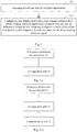
- the embodiment of the present disclosure provides a method for configuring a signal. As shown in Fig.1 , the method includes the following steps.
- Step 101 acquiring at least one type of reference information, wherein the reference information is used to characterize a configuration status of a communication network.
- Step 102 configuring time domain and/or frequency domain resources for a phase-tracking reference signal based on the at least one type of reference information, and obtaining configuration information of the time domain and/or frequency domain resources for the phase-tracking reference signal, wherein the configuration information includes a density or a pattern corresponding to the time domain and/or frequency domain resources.
- the at least one type of reference information includes at least one of following: a phase-noise single-side-band power spectrum density, a modulation and coding scheme (MCS), a sub-carrier interval, an amount of time domain and/or frequency domain resource blocks to be scheduled, and a communication waveform.
- MCS modulation and coding scheme
- the phase-noise single-side-band power spectrum density may be obtained by using a phase noise model. It is certainly understood that the phase-noise single-side-band power spectrum density may be obtained by other means, and an exhaustive enumeration of the other means is omitted herein.
- the phase-noise single-side-band power spectrum density has a profile associated with a cost, a frequency band, a manufacturing process and a power consumption of the local oscillator, and a detailed description thereof is omitted herein.
- the MCS refers to modulation and coding schemes, which is used to number various modulation and coding schemes, so that different communication schemes may be employed by the system.
- a MCS index is used in 802.11 communication systems for configuring a wireless communication data rate to cope with different communication environments.
- the configuring the time domain and/or frequency domain resources for the phase-tracking reference signal based on the at least one type of reference information includes at least one of following steps: based on at least the phase-noise single-side-band power spectrum density corresponding to an increasing frequency offset, configuring the time domain and/or frequency domain resources for the phase-tracking reference signal; based on at least the MCS, configuring the time domain and/or frequency domain resources for the phase-tracking reference signal; based on at least the sub-carrier interval, configuring the time domain and/or frequency domain resources for the phase-tracking reference signal; based on at least the amount of time domain and/or frequency domain resource blocks to be scheduled, configuring the time domain and/or frequency domain resources for the phase-tracking reference signal; based on at least the communication waveform, configuring the time domain and/or frequency domain resources for the phase-tracking reference signal.
- a density of the time domain and/or frequency domain resources for the phase-tracking reference signal is configured to be in a first density threshold range; and if the decline rate of the phase-noise single-side-band power spectrum density decreases with the frequency offset being increased, the density of the time domain and/or frequency domain resources for the phase-tracking reference signal is configured to be in a second density threshold range; wherein values in the first density threshold range are less than values in the second density threshold range; density threshold subsets that may or may not overlap with each other are included in the first density threshold range or the second density threshold range.
- phase noise model there is a relationship between the phase noise model and configuration of the time domain and/or frequency domain resources for the phase-tracking reference signal: the lower the decline rate of the phase-noise single-side-band power spectrum density with the frequency offset being increased is, the higher density of the time domain and/or frequency domain resources for the phase-tracking reference signal is required; and the faster the decline rate of the phase-noise single-side-band power spectrum density with the frequency offset being increased is, the lower density of the time domain and/or frequency domain resources of the phase-tracking reference signal is required.
- an upper limit may be set to a density to which consecutive resources in the time domain and less than 10% of resources in frequency domain correspond.
- the density of the time domain and/or frequency domain resources for the phase-tracking reference signal is configured to be in the first density threshold range; and when the MCS is in a second preset range, the density of the time domain and/or frequency domain resources for the phase-tracking reference signal is configured to be in the second density threshold range; wherein values in the first preset range are less than values in the second preset range and values in the first density threshold range are less than values in the second density threshold range.
- Preset subsets that may or may not overlap with each other are included in the first preset range or in the second preset range.
- a lower MCS entails a lower density of the time domain and/or frequency domain resources for the phase-tracking reference signal
- a higher MCS entails a higher density of the time domain and/or frequency domain resources for the phase-tracking reference signal
- the sub-carrier interval when the sub-carrier interval is in a third preset range, the density of the time domain and/or frequency domain resources for the phase-tracking reference signal is configured to be in the first density threshold range; and when the sub-carrier interval is in a fourth preset range, the density of the time domain and/or frequency domain resources for the phase-tracking reference signal is configured to be in the second density threshold range; wherein values in the third preset range are greater than values in the fourth preset range.
- the third preset range or the fourth preset range may respectively include at least one preset range subset, a detailed description thereof is omitted herein.
- An underlying rule existing in the mapping table may be: the greater the sub-carrier interval is, the lower density of the time domain and/or frequency domain resources for the phase-tracking reference signal is required; and the lesser the sub-carrier interval is, the higher density of the time domain and/or frequency domain resources for the phase-tracking reference signal is required; or, classes of sub-carrier intervals may be preset, and if the sub-carrier interval falls within a first class, it is determined to configure the density of the time domain and/or frequency domain resources by using a first density, and so forth; wherein density values for respective classes are different from each other.
- the density of the time domain and/or frequency domain resources is configured to be a first density; when the communication waveform is an Orthogonal Frequency Division Multiplexing (OFDM) waveform, the density of the time domain and/or frequency domain resources is configured to be a second density; wherein the first density is less than the second density.
- OFDM Orthogonal Frequency Division Multiplexing
- Determination of the density of the time domain and/or frequency domain resources of the phase-tracking reference signal based on the communication waveform may be understood as: according to a relationship between the waveform and configuration of the time domain and/or frequency domain resources of the phase-tracking reference signal, a density of the time domain and/or frequency domain resources required by a system based on the single-carrier waveform is less than that required by a system based on the OFDM waveform.
- information about the pattern configuration may be transmitted to the receiving end via an explicit or implicit signaling indication.
- the method further includes: transmitting the pattern of the time domain and/or frequency domain resources of the phase-tracking reference signal to the receiving end via at least one of Downlink Control Information (DCI), Radio Resource Control (RRC), and a Uplink (UL) grant; or transmitting the pattern of the time domain and/or frequency domain resources of the phase-tracking reference signal to the receiving end via Uplink Control Information (UCI) or the like.
- DCI Downlink Control Information
- RRC Radio Resource Control
- UL Uplink
- UCI Uplink Control Information
- the result is transmitted to the terminal via a downlink signaling.
- the result is transmitted to the terminal via a signaling indication including at least one of the DCI, the RRC, and the UL grant.
- the result is transmitted to the base station via a uplink signaling. Specifically, the result is transmitted to the base station via a signaling indication including the UCI or the like.
- Indication information indicating that at least one type of reference information is associated with a configuration of time domain and/or frequency domain resources of the phase-tracking reference signal is transmitted to the receiving end via at least one of the DCI, the RRC or the UL grant.
- the indication information indicating that at least one type of reference information is associated with the configuration of time domain and/or frequency domain resources of the phase-tracking reference signal is transmitted to the receiving end via the UCI or the like.
- the terminal is informed, in a downlink direction via the signaling indication including at least one of the DCI, the RRC and the UL grant, of indication information indicating that the configuration of time domain and/or frequency domain resources of the phase-tracking reference signal is associated with the phase noise model or with the MCS or with the sub-carrier interval or with the RBs to be scheduled or with the waveform; the terminal derives the configuration of the time domain and/or frequency domain resources of the phase-tracking reference signal based on the indication information by means of searching a look-up table, etc.
- the base station In a case that the terminal informs the base station of the information about the configuration, the base station is informed, in a uplink direction via the signaling indication including the UCI, of indication information indicating that the configuration of the time domain and/or frequency domain resources of the phase-tracking reference signal is associated with the phase noise model or with the MCS or with the sub-carrier interval or with the RBs to be scheduled or with the waveform; the base station derives the configuration of the time domain and/or frequency domain resources of the phase-tracking reference signal based on the indication information by means of searching a look-up table, etc.
- the method further includes: determining whether at least one type of reference signal is configured at a resource location corresponding to the pattern of the time domain and/or frequency domain resources or not, wherein the at least one type of reference signal is a reference signal different from the phase-tracking reference signal; in a case that the at least one type of reference signal is configured at the resource location corresponding to the pattern of the time domain and/or frequency domain resources, multiplexing the phase-tracking reference signal with the configured at least one type of reference signal.
- the reference signal different from the phase-tracking reference signal includes known uplink and downlink signals used for functions such as channel estimation, channel measurement or synchronization, e.g., a Demodulation Reference Signal (DMRS), a Channel State Information Reference Signal (CSI-RS) or a Sounding Reference Signal (SRS), etc.
- DMRS Demodulation Reference Signal
- CSI-RS Channel State Information Reference Signal
- SRS Sounding Reference Signal
- the phase-tracking reference signal may be multiplexed with known other reference signals adequately.
- the term "multiplex" herein refers to, if the known other reference signals have occupied corresponding time domain and/or frequency domain resources, it is unnecessary to configure the phase-tracking reference signal.
- the known other reference signal is adapted for functions such as the channel estimation, the channel measurement or the synchronization, the detailed description of transmitted information of the other reference signal is omitted herein.
- the method further includes: in a case that the at least one type of reference signal is configured at the resource location corresponding to the pattern of the time domain and/or frequency domain resources, determining whether the at least one type of reference signal occupies all resource locations corresponding to the pattern of the time domain and/or frequency domain resources of the phase-tracking reference signal or not; in a case that at least one time domain and/or frequency domain resource location of the all resource locations is unoccupied, configuring the phase-tracking reference signal at the unoccupied at least one time domain and/or frequency domain resource location.
- a quantity of time domain and/or frequency domain resources required by the phase-tracking reference signal is associated with the phase noise model, the MCS, the sub-carrier interval, the RBs to be scheduled and the waveform. If a quantity of time domain and/or frequency domain resources of other reference signals different from the phase-tracking reference signal is currently insufficient, the unoccupied time domain and/or frequency domain resources should be complemented correspondingly according to the obtained configuration of the phase-tracking reference signal.
- the configuration of the time domain and/or frequency domain resources of the phase-tracking signal may be implemented based on the reference information by means of the aforementioned solution, and in this way, the problem that an excessive signal overhead resulting from inflexible configuration of the phase-tracking reference signal is solved, thereby improving a frequency-spectrum efficiency of the phase-tracking reference signal.
- the embodiment of the present disclosure provides a device for configuring a signal.
- the device includes a reference information acquisition unit 21 and a configuration unit 22.
- the reference information acquisition unit 21 is configured to acquire at least one type of reference information, wherein the reference information is used to characterize a configuration status of a communication network.
- the configuration unit 22 is configured to configure time domain and/or frequency domain resources for the phase-tracking reference signal based on the at least one type of reference information, and obtain configuration information of the time domain and/or frequency domain resources for the phase-tracking reference signal, wherein the configuration information includes a density or a pattern corresponding to the time domain and/or frequency domain resources.
- the at least one type of reference information includes at least one of following: a phase-noise single-side-band power spectrum density, a modulation and coding scheme (MCS), a sub-carrier interval, an amount of time domain and/or frequency domain resource blocks to be scheduled, and a communication waveform.
- MCS modulation and coding scheme
- the phase-noise single-side-band power spectrum density may be obtained by using a phase noise model. It is certainly understood that the phase-noise single-side-band power spectrum density may be obtained by other means, and an exhaustive enumeration of the other means is omitted herein.
- the phase-noise single-side-band power spectrum density has a profile associated with a cost, a frequency band, a manufacturing process and a power consumption of the local oscillator, and a detailed description thereof is omitted herein.
- the MCS refers to modulation and coding schemes, which is used to number various modulation and coding schemes, so that different communication schemes may be employed by the system.
- a MCS index is used in 802.11 communication systems for configuring a wireless communication data rate to cope with different communication environments.
- the configuration unit is configured to perform at least one of following: based on at least the phase-noise single-side-band power spectrum density corresponding to an increasing frequency offset, configuring the time domain and/or frequency domain resources for the phase-tracking reference signal; based on at least the MCS, configuring the time domain and/or frequency domain resources for the phase-tracking reference signal; based on at least the sub-carrier interval, configuring the time domain and/or frequency domain resources for the phase-tracking reference signal; based on at least the amount of time domain and/or frequency domain resource blocks to be scheduled, configuring the time domain and/or frequency domain resources for the phase-tracking reference signal; based on at least the communication waveform, configuring the time domain and/or frequency domain resources for the phase-tracking reference signal.
- a density of the time domain and/or frequency domain resources for the phase-tracking reference signal is configured to be in a first density threshold range; and if the decline rate of the phase-noise single-side-band power spectrum density decreases with the frequency offset being increased, the density of the time domain and/or frequency domain resources for the phase-tracking reference signal is configured to be in a second density threshold range; wherein values in the first density threshold range are less than values in the second density threshold range; density threshold subsets that may or may not overlap with each other are included in the first density threshold range or the second density threshold range.
- phase noise model there is a relationship between the phase noise model and configuration of the time domain and/or frequency domain resources for the phase-tracking reference signal: the lower the decline rate of the phase-noise single-side-band power spectrum density with the frequency offset being increased is, the higher density of the time domain and/or frequency domain resources for the phase-tracking reference signal is required; and the faster the decline rate of the phase-noise single-side-band power spectrum density with the frequency offset being increased is, the lower density of the time domain and/or frequency domain resources of the phase-tracking reference signal is required.
- an upper limit may be set to a density to which consecutive resources in the time domain and less than 10% of resources in frequency domain correspond.
- the density of the time domain and/or frequency domain resources for the phase-tracking reference signal is configured to be in the first density threshold range; and when the MCS is in a second preset range, the density of the time domain and/or frequency domain resources for the phase-tracking reference signal is configured to be in the second density threshold range; wherein values in the first preset range are less than values in the second preset range and values in the first density threshold range are less than values in the second density threshold range.
- Preset subsets that may or may not overlap with each other are included in the first preset range or in the second preset range.
- a lower MCS entails a lower density of the time domain and/or frequency domain resources for the phase-tracking reference signal
- a higher MCS entails a higher density of the time domain and/or frequency domain resources for the phase-tracking reference signal
- the sub-carrier interval when the sub-carrier interval is in a third preset range, the density of the time domain and/or frequency domain resources for the phase-tracking reference signal is configured to be in the first density threshold range; and when the sub-carrier interval is in a fourth preset range, the density of the time domain and/or frequency domain resources for the phase-tracking reference signal is configured to be in the second density threshold range; wherein values in the third preset range are greater than values in the fourth preset range.
- the third preset range or the fourth preset range may respectively include at least one preset range subset, a detailed description thereof is omitted herein.
- the density of the time domain and/or frequency domain resources is configured to be a first density; when the communication waveform is an Orthogonal Frequency Division Multiplexing (OFDM) waveform, the density of the time domain and/or frequency domain resources is configured to be a second density; wherein the first density is less than the second density.
- OFDM Orthogonal Frequency Division Multiplexing
- Determination of the density of the time domain and/or frequency domain resources of the phase-tracking reference signal based on the communication waveform may be understood as: according to a relationship between the waveform and configuration of the time domain and/or frequency domain resources of the phase-tracking reference signal, a density of the time domain and/or frequency domain resources required by a system based on the single-carrier waveform is less than that required by a system based on the OFDM waveform.
- information about the pattern configuration may be transmitted to the receiving end via an explicit or implicit signaling indication.
- the device further includes a communication unit 23.
- the communication unit 23 is configured to: transmit the pattern of the time domain and/or frequency domain resources of the phase-tracking reference signal to the receiving end via at least one of Downlink Control Information (DCI), a Radio Resource Control (RRC) signaling, and a Uplink (UL) grant; or transmit the pattern of the time domain and/or frequency domain resources of the phase-tracking reference signal to the receiving end via Uplink Control Information (UCI) or the like.
- DCI Downlink Control Information
- RRC Radio Resource Control
- UL Uplink
- UCI Uplink Control Information
- the result is transmitted to the terminal via a downlink signaling.
- the result is transmitted to the terminal via a signaling indication including at least one of the DCI, the RRC signaling, and the UL grant.
- the result is transmitted to the base station via a uplink signaling. Specifically, the result is transmitted to the base station via a signaling indication including the UCI or the like.
- the communication unit 23 is configured to transmit, to the receiving end via at least one of the DCI, the RRC signaling or the UL grant, indication information indicating that at least one type of reference information is associated with a configuration of time domain and/or frequency domain resources of the phase-tracking reference signal.
- the communication unit 23 is configured to transmit, to the receiving end via the UCI or the like, the indication information indicating that at least one type of reference information is associated with the configuration of time domain and/or frequency domain resources of the phase-tracking reference signal.
- the terminal is informed, in a downlink direction via the signaling indication including at least one of the DCI, the RRC signaling and the UL grant, of the indication information indicating that the configuration of time domain and/or frequency domain resources of the phase-tracking reference signal is associated with the phase noise model or with the MCS or with the sub-carrier interval or with the RBs to be scheduled or with the waveform; the terminal derives the configuration of the time domain and/or frequency domain resources of the phase-tracking reference signal based on the indication information by means of searching a look-up table, etc.
- the base station In a case that the terminal informs the base station of the information about the configuration, the base station is informed, in a uplink direction via the signaling indication including the UCI, of the indication information indicating that the configuration of the time domain and/or frequency domain resources of the phase-tracking reference signal is associated with the phase noise model or with the MCS or with the sub-carrier interval or with the RBs to be scheduled or with the waveform; the base station derives the configuration of the time domain and/or frequency domain resources of the phase-tracking reference signal based on the indication information by means of searching a look-up table, etc.
- the configuration unit is further configured to: determine whether at least one type of reference signal is configured at a resource location corresponding to the pattern of the time domain and/or frequency domain resources or not, wherein the at least one type of reference signal is a reference signal different from the phase-tracking reference signal; in a case that the at least one type of reference signal is configured at the resource location corresponding to the pattern of the time domain and/or frequency domain resources, multiplex the phase-tracking reference signal with the configured at least one type of reference signal.
- the reference signal different from the phase-tracking reference signal includes known uplink and downlink signals used for functions such as channel estimation, channel measurement or synchronization, e.g., a Demodulation Reference Signal (DMRS), a Channel State Information Reference Signal (CSI-RS) or a Sounding Reference Signal (SRS), etc.
- DMRS Demodulation Reference Signal
- CSI-RS Channel State Information Reference Signal
- SRS Sounding Reference Signal
- the phase-tracking reference signal may be multiplexed with known other reference signals adequately.
- the configuration unit is further configured to: in a case that the at least one type of reference signal is configured at the resource location corresponding to the pattern of the time domain and/or frequency domain resources, determine whether the at least one type of reference signal occupies all resource locations corresponding to the pattern of the time domain and/or frequency domain resources of the phase-tracking reference signal or not; in a case that at least one time domain and/or frequency domain resource location of the all resource locations is unoccupied, configure the phase-tracking reference signal at the unoccupied at least one time domain and/or frequency domain resource location.
- a quantity of time domain and/or frequency domain resources required by the phase-tracking reference signal is associated with the phase noise model, the MCS, the sub-carrier interval, the RBs to be scheduled and the waveform. If a quantity of time domain and/or frequency domain resources of other reference signals different from the phase-tracking reference signal is currently insufficient, the unoccupied time domain and/or frequency domain resources should be complemented correspondingly according to the obtained configuration of the phase-tracking reference signal.
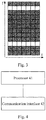
- Fig.3 illustrates a inflexible configuration pattern of the phase-tracking reference signal in the related art.
- time domain and frequency domain resources corresponding to light-colored blocks denote fixed locations of the time domain and/or frequency domain resources configured for the phase-tracking reference signal.
- the time domain and/or frequency domain resources are configured for the phase-tracking reference signal in a more flexible manner, so that the problem that the excessive signal overhead resulting from the inflexible configuration for the phase-tracking reference signal is solved, thereby improving the frequency spectrum efficiency of the phase-tracking reference signal.
- the embodiment of the present disclosure provides a device for configuring a signal.
- the device for configuring a signal includes a processor 41 and a communication interface 42.
- the processor 41 is configured to: acquire at least one type of reference information, wherein the reference information is used to characterize a configuration status of a communication network; configure time domain and/or frequency domain resources for the phase-tracking reference signal based on the at least one type of reference information, and obtain configuration information of the time domain and/or frequency domain resources for the phase-tracking reference signal, wherein the configuration information includes a density or a pattern corresponding to the time domain and/or frequency domain resources.
- the at least one type of reference information includes at least one of following: a phase-noise single-side-band power spectrum density, a modulation and coding scheme (MCS), a sub-carrier interval, an amount of time domain and/or frequency domain resource blocks to be scheduled, and a communication waveform.
- MCS modulation and coding scheme
- the phase-noise single-side-band power spectrum density may be obtained by using a phase noise model. It is certainly understood that the phase-noise single-side-band power spectrum density may be obtained by other means, and an exhaustive enumeration of the other means is omitted herein.
- the phase-noise single-side-band power spectrum density has a profile associated with a cost, a frequency band, a manufacturing process and a power consumption of the local oscillator, and a detailed description thereof is omitted herein.
- the MCS refers to modulation and coding schemes, which is used to number various modulation and coding schemes, so that different communication schemes may be employed by the system.
- a MCS index is used in 802.11 communication systems for configuring a wireless communication data rate to cope with different communication environments.
- the processor 41 is configured to perform at least one of following: based on at least the phase-noise single-side-band power spectrum density corresponding to an increasing frequency offset, configuring the time domain and/or frequency domain resources for the phase-tracking reference signal; based on at least the MCS, configuring the time domain and/or frequency domain resources for the phase-tracking reference signal; based on at least the sub-carrier interval, configuring the time domain and/or frequency domain resources for the phase-tracking reference signal; based on at least the amount of time domain and/or frequency domain resource blocks to be scheduled, configuring the time domain and/or frequency domain resources for the phase-tracking reference signal; based on at least the communication waveform, configuring the time domain and/or frequency domain resources for the phase-tracking reference signal.
- a density of the time domain and/or frequency domain resources for the phase-tracking reference signal is configured to be in a first density threshold range; and if the decline rate of the phase-noise single-side-band power spectrum density decreases with the frequency offset being increased, the density of the time domain and/or frequency domain resources for the phase-tracking reference signal is configured to be in a second density threshold range; wherein values in the first density threshold range are less than values in the second density threshold range; density threshold subsets that may or may not overlap with each other are included in the first density threshold range or the second density threshold range.
- phase noise model there is a relationship between the phase noise model and configuration of the time domain and/or frequency domain resources for the phase-tracking reference signal: the lower the decline rate of the phase-noise single-side-band power spectrum density with the frequency offset being increased is, the higher density of the time domain and/or frequency domain resources for the phase-tracking reference signal is required; and the faster the decline rate of the phase-noise single-side-band power spectrum density with the frequency offset being increased is, the lower density of the time domain and/or frequency domain resources of the phase-tracking reference signal is required.
- an upper limit may be set to a density to which consecutive resources in the time domain and less than 10% of resources in frequency domain correspond.
- the density of the time domain and/or frequency domain resources for the phase-tracking reference signal is configured to be in the first density threshold range; and when the MCS is in a second preset range, the density of the time domain and/or frequency domain resources for the phase-tracking reference signal is configured to be in the second density threshold range; wherein values in the first preset range are less than values in the second preset range and values in the first density threshold range are less than values in the second density threshold range.
- Preset subsets that may or may not overlap with each other are included in the first preset range or in the second preset range.
- a lower MCS entails a lower density of the time domain and/or frequency domain resources for the phase-tracking reference signal
- a higher MCS entails a higher density of the time domain and/or frequency domain resources for the phase-tracking reference signal
- the sub-carrier interval when the sub-carrier interval is in a third preset range, the density of the time domain and/or frequency domain resources for the phase-tracking reference signal is configured to be in the first density threshold range; and when the sub-carrier interval is in a fourth preset range, the density of the time domain and/or frequency domain resources for the phase-tracking reference signal is configured to be in the second density threshold range; wherein values in the third preset range are greater than values in the fourth preset range.
- the third preset range or the fourth preset range may respectively include at least one preset range subset, a detailed description thereof is omitted herein.
- the density of the time domain and/or frequency domain resources is configured to be a first density; when the communication waveform is an Orthogonal Frequency Division Multiplexing (OFDM) waveform, the density of the time domain and/or frequency domain resources is configured to be a second density; wherein the first density is less than the second density.
- OFDM Orthogonal Frequency Division Multiplexing
- Determination of the density of the time domain and/or frequency domain resources of the phase-tracking reference signal based on the communication waveform may be understood as: according to a relationship between the waveform and configuration of the time domain and/or frequency domain resources of the phase-tracking reference signal, a density of the time domain and/or frequency domain resources required by a system based on the single-carrier waveform is less than that required by a system based on the OFDM waveform.
- information about the pattern configuration may be transmitted to the receiving end via an explicit or implicit signaling indication.
- the device further includes the communication interface 42.
- the communication interface 42 is configured to: transmit the pattern of the time domain and/or frequency domain resources of the phase-tracking reference signal to the receiving end via at least one of Downlink Control Information (DCI), a Radio Resource Control (RRC) signaling, and a Uplink (UL) grant; or transmit the pattern of the time domain and/or frequency domain resources of the phase-tracking reference signal to the receiving end via Uplink Control Information (UCI) or the like.
- DCI Downlink Control Information
- RRC Radio Resource Control
- UL Uplink
- UCI Uplink Control Information
- the result is transmitted to the terminal via a downlink signaling.
- the result is transmitted to the terminal via a signaling indication including at least one of the DCI, the RRC signaling, and the UL grant.
- the result is transmitted to the base station via a uplink signaling. Specifically, the result is transmitted to the base station via a signaling indication including the UCI or the like.
- the communication interface 42 is configured to transmit, to the receiving end via at least one of the DCI, the RRC signaling or the UL grant, indication information indicating that at least one type of reference information is associated with a configuration of time domain and/or frequency domain resources of the phase-tracking reference signal.
- the communication interface 42 is configured to transmit, to the receiving end via the UCI or the like, the indication information indicating that at least one type of reference information is associated with the configuration of time domain and/or frequency domain resources of the phase-tracking reference signal.
- the terminal is informed, in a downlink direction via the signaling indication including at least one of the DCI, the RRC signaling and the UL grant, of the indication information indicating that the configuration of time domain and/or frequency domain resources of the phase-tracking reference signal is associated with the phase noise model or with the MCS or with the sub-carrier interval or with the RBs to be scheduled or with the waveform; the terminal derives the configuration of the time domain and/or frequency domain resources of the phase-tracking reference signal based on the indication information by means of searching a look-up table, etc.
- the base station In a case that the terminal informs the base station of the information about the configuration, the base station is informed, in a uplink direction via the signaling indication including the UCI, of the indication information indicating that the configuration of the time domain and/or frequency domain resources of the phase-tracking reference signal is associated with the phase noise model or with the MCS or with the sub-carrier interval or with the RBs to be scheduled or with the waveform; the base station derives the configuration of the time domain and/or frequency domain resources of the phase-tracking reference signal based on the indication information by means of searching a look-up table, etc.
- the processor 41 is further configured to: determine whether at least one type of reference signal is configured at a resource location corresponding to the pattern of the time domain and/or frequency domain resources or not, wherein the at least one type of reference signal is a reference signal different from the phase-tracking reference signal; in a case that the at least one type of reference signal is configured at the resource location corresponding to the pattern of the time domain and/or frequency domain resources, multiplex the phase-tracking reference signal with the configured at least one type of reference signal.
- the reference signal different from the phase-tracking reference signal includes known uplink and downlink signals used for functions such as channel estimation, channel measurement or synchronization, e.g., a Demodulation Reference Signal (DMRS), a Channel State Information Reference Signal (CSI-RS) or a Sounding Reference Signal (SRS), etc.
- DMRS Demodulation Reference Signal
- CSI-RS Channel State Information Reference Signal
- SRS Sounding Reference Signal
- the phase-tracking reference signal may be multiplexed with known other reference signals adequately.
- the processor 41 is further configured to: in a case that the at least one type of reference signal is configured at the resource location corresponding to the pattern of the time domain and/or frequency domain resources, determine whether the at least one type of reference signal occupies all resource locations corresponding to the pattern of the time domain and/or frequency domain resources of the phase-tracking reference signal or not; in a case that at least one time domain and/or frequency domain resource location of the all resource locations is unoccupied, configure the phase-tracking reference signal at the unoccupied at least one time domain and/or frequency domain resource location.
- a quantity of time domain and/or frequency domain resources required by the phase-tracking reference signal is associated with the phase noise model, the MCS, the sub-carrier interval, the RBs to be scheduled and the waveform. If a quantity of time domain and/or frequency domain resources of other reference signals different from the phase-tracking reference signal is currently insufficient, the unoccupied time domain and/or frequency domain resources should be complemented correspondingly according to the obtained configuration of the phase-tracking reference signal.
- Fig.3 illustrates the inflexible configuration pattern of the phase-tracking reference signal in the related art.
- time domain and frequency domain resources corresponding to light-colored blocks denote fixed locations of the time domain and/or frequency domain resources configured for the phase-tracking reference signal.
- the time domain and/or frequency domain resources are configured for the phase-tracking reference signal in a more flexible manner, so that the problem that the excessive signal overhead resulting from the inflexible configuration for the phase-tracking reference signal is solved, thereby improving the frequency spectrum efficiency of the phase-tracking reference signal.
- the embodiments of the present disclosure further provide a device for configuring a signal.
- the device for configuring a signal includes at least one processor, a storage and at least one network interface.
- the at least one processor, the storage and the at least one network interface are coupled to each other via a bus system.
- the storage in the embodiments of the present disclosure may be a volatile storage or a non-volatile storage, or include both the volatile storage and the non-volatile storage.
- the storage stores executable modules or data structures, or subsets thereof, or supersets thereof including operating systems and applications.
- the processor is configured to perform the steps of the method according to the aforementioned first embodiment. A detailed description thereof is omitted herein.
- Some embodiments of the present disclosure provide a storage medium.
- the storage medium stores computer executable instructions, wherein when the computer executable instructions are executed, the steps of the method according to the aforementioned first embodiment are performed.
- the method according to the embodiments may be implemented not only by software in conjunction with necessary generic hardware platform, but also by hardware, although the former will be preferred in most cases.
- a storage medium e.g., a Read Only Memory (ROM)/ Random Access Memory (RAM), a magnetic disk and an optical disc
- ROM Read Only Memory
- RAM Random Access Memory
- magnetic disk e.g., a magnetic disk
- optical disc e.g., a magnetic disk and an optical disc
- the software product is stored in a storage medium (e.g., a Read Only Memory (ROM)/ Random Access Memory (RAM), a magnetic disk and an optical disc) and includes several instructions adapted to be executed by a terminal device (such as a handset, a computer, an apparatus, an air conditioner or a network device) to perform the method according to the embodiments of the present disclosure.
- a terminal device such as a handset, a computer, an apparatus, an air conditioner or a network device
Landscapes
- Engineering & Computer Science (AREA)
- Signal Processing (AREA)
- Computer Networks & Wireless Communication (AREA)
- Quality & Reliability (AREA)
- Power Engineering (AREA)
- Mobile Radio Communication Systems (AREA)
Applications Claiming Priority (2)
| Application Number | Priority Date | Filing Date | Title |
|---|---|---|---|
| CN201710008062.0A CN108282281B (zh) | 2017-01-05 | 2017-01-05 | 一种信号配置方法及装置 |
| PCT/CN2018/071570 WO2018127132A1 (fr) | 2017-01-05 | 2018-01-05 | Procédé et dispositif de traitement de signal et support d'informations |
Publications (3)
| Publication Number | Publication Date |
|---|---|
| EP3567785A1 true EP3567785A1 (fr) | 2019-11-13 |
| EP3567785A4 EP3567785A4 (fr) | 2020-09-09 |
| EP3567785B1 EP3567785B1 (fr) | 2025-12-03 |
Family
ID=62789228
Family Applications (1)
| Application Number | Title | Priority Date | Filing Date |
|---|---|---|---|
| EP18736503.6A Active EP3567785B1 (fr) | 2017-01-05 | 2018-01-05 | Procédé et dispositif de traitement de signal et support d'informations |
Country Status (5)
| Country | Link |
|---|---|
| US (1) | US10965414B2 (fr) |
| EP (1) | EP3567785B1 (fr) |
| JP (2) | JP2020504545A (fr) |
| CN (1) | CN108282281B (fr) |
| WO (1) | WO2018127132A1 (fr) |
Cited By (1)
| Publication number | Priority date | Publication date | Assignee | Title |
|---|---|---|---|---|
| US20220166565A1 (en) * | 2017-04-28 | 2022-05-26 | Panasonic Intellectual Property Corporation Of America | Measurement apparatus and measurement method |
Families Citing this family (15)
| Publication number | Priority date | Publication date | Assignee | Title |
|---|---|---|---|---|
| US11070335B2 (en) | 2017-01-13 | 2021-07-20 | Qualcomm Incorporated | Apparatus and method for determining resources for phase tracking reference signal (PT-RS) pilot signals using frequency domain patterns |
| CN109150447B (zh) * | 2017-06-16 | 2022-09-27 | 中兴通讯股份有限公司 | 信息发送、数据解调方法及装置、通信节点、网络侧设备 |
| US10701724B2 (en) * | 2018-01-12 | 2020-06-30 | Apple Inc. | Time density and frequency density determination of phase tracking reference signals (PT-RS) in new radio (NR) systems |
| US11051327B2 (en) * | 2018-08-10 | 2021-06-29 | Qualcomm Incorporated | Rate-matching around CRS for NR-TDD |
| CN110855406B (zh) * | 2018-08-20 | 2022-05-03 | 大唐移动通信设备有限公司 | 相位跟踪参考信号ptrs传输方法、网络设备及终端 |
| CN111800865A (zh) * | 2019-08-12 | 2020-10-20 | 维沃移动通信有限公司 | 一种信号发送方法及发送设备 |
| WO2021062719A1 (fr) * | 2019-09-30 | 2021-04-08 | Nec Corporation | Procédés de communication, dispositif terminal, dispositif de réseau et support lisible par ordinateur |
| WO2021146990A1 (fr) * | 2020-01-22 | 2021-07-29 | 华为技术有限公司 | Procédé et appareil de transmission de signal de référence de suivi de phase |
| CN111417187B (zh) * | 2020-03-25 | 2022-02-22 | 展讯通信(上海)有限公司 | 实际trs频域资源的确定方法及装置、存储介质、ue |
| WO2022016503A1 (fr) * | 2020-07-24 | 2022-01-27 | Qualcomm Incorporated | Configurations de signal de référence de suivi de phase multiple pour un équipement utilisateur |
| CN115022465B (zh) * | 2022-05-27 | 2025-06-27 | 三星半导体(中国)研究开发有限公司 | 通话测试系统和方法 |
| CN117692945A (zh) * | 2022-08-29 | 2024-03-12 | 维沃移动通信有限公司 | 感知信号处理方法、装置及通信设备 |
| JP2025533958A (ja) * | 2022-10-10 | 2025-10-09 | ノキア テクノロジーズ オサケユイチア | 復調基準信号の時間領域リソース割り当て |
| CN116506093B (zh) * | 2023-06-26 | 2023-08-18 | 北京智芯微电子科技有限公司 | 下行解调参考信号的配置方法、装置、设备、芯片及介质 |
| US12531711B2 (en) * | 2023-09-28 | 2026-01-20 | Qualcomm Incorporated | Enhanced PTRS for mitigation of phase noise |
Family Cites Families (10)
| Publication number | Priority date | Publication date | Assignee | Title |
|---|---|---|---|---|
| CN100563143C (zh) * | 2006-01-19 | 2009-11-25 | 华为技术有限公司 | 一种导频映射方法和无线通信系统 |
| CN101714897B (zh) * | 2009-11-12 | 2013-01-02 | 普天信息技术研究院有限公司 | 探测参考信号的配置方法 |
| JP5642875B2 (ja) * | 2010-04-30 | 2014-12-17 | テレフオンアクチーボラゲット エル エム エリクソン(パブル) | 負荷分担電力制御のための方法および装置 |
| CN102780532B (zh) * | 2011-05-09 | 2016-06-08 | 华为技术有限公司 | 信道测量的方法及装置 |
| US9942016B2 (en) * | 2014-03-21 | 2018-04-10 | Futurewei Technologies, Inc. | Device, network, and method for network adaptation and discovery |
| US10595225B2 (en) * | 2016-09-13 | 2020-03-17 | Qualcomm Incorporated | Phase-noise compensation reference signal configuration reporting and signaling |
| CN110024322A (zh) | 2016-09-28 | 2019-07-16 | Idac控股公司 | 用于无线通信系统的参考信号设计 |
| BR112019006262B1 (pt) | 2016-09-30 | 2022-10-11 | Lg Electronics Inc | Método e equipamento de usuário para receber informação de controle para sinal de referência relacionado à estimativa de ruído de fase |
| CN107888530B (zh) | 2016-09-30 | 2021-01-22 | 电信科学技术研究院 | 相位噪声补偿参考信号的传输方法、发送设备及接收设备 |
| EP3535884A1 (fr) * | 2016-11-04 | 2019-09-11 | Telefonaktiebolaget LM Ericsson (publ) | Configuration de pt-rs en fonction de paramètres de planification |
-
2017
- 2017-01-05 CN CN201710008062.0A patent/CN108282281B/zh active Active
-
2018
- 2018-01-05 JP JP2019536921A patent/JP2020504545A/ja active Pending
- 2018-01-05 US US16/475,852 patent/US10965414B2/en active Active
- 2018-01-05 WO PCT/CN2018/071570 patent/WO2018127132A1/fr not_active Ceased
- 2018-01-05 EP EP18736503.6A patent/EP3567785B1/fr active Active
-
2021
- 2021-06-24 JP JP2021105033A patent/JP7230119B2/ja active Active
Cited By (2)
| Publication number | Priority date | Publication date | Assignee | Title |
|---|---|---|---|---|
| US20220166565A1 (en) * | 2017-04-28 | 2022-05-26 | Panasonic Intellectual Property Corporation Of America | Measurement apparatus and measurement method |
| US11711178B2 (en) * | 2017-04-28 | 2023-07-25 | Panasonic Intellectual Property Corporation Of America | Measurement apparatus and measurement method |
Also Published As
| Publication number | Publication date |
|---|---|
| EP3567785A4 (fr) | 2020-09-09 |
| CN108282281B (zh) | 2020-02-21 |
| JP2020504545A (ja) | 2020-02-06 |
| US20190356437A1 (en) | 2019-11-21 |
| JP2021168487A (ja) | 2021-10-21 |
| EP3567785B1 (fr) | 2025-12-03 |
| WO2018127132A1 (fr) | 2018-07-12 |
| CN108282281A (zh) | 2018-07-13 |
| JP7230119B2 (ja) | 2023-02-28 |
| US10965414B2 (en) | 2021-03-30 |
Similar Documents
| Publication | Publication Date | Title |
|---|---|---|
| US10965414B2 (en) | Signal configuration method, device and storage medium | |
| CN108809598B (zh) | 一种通信方法及装置 | |
| US11757511B2 (en) | Ordering of CSI in UCI | |
| US10284314B2 (en) | Measurements in a wireless system | |
| BR112019026152B1 (pt) | Método de comunicação sem fio, aparelho de comunicações, meio de armazenamento em computador, e aparelho de comunicação | |
| US11523418B2 (en) | Method and apparatus for resource indication | |
| EP3089512A1 (fr) | Dispositif de terminal et dispositif de station de base | |
| US20110235604A1 (en) | Communication system, communication method, base station, mobile station, and program | |
| KR20190034577A (ko) | 파일럿 신호를 전송하는 방법, 단말 장비 및 네트워크 측 장비 | |
| US9520976B2 (en) | Mobile communication method, wireless base station and mobile station | |
| US20190349164A1 (en) | Reference signal configuration method, base station, and terminal | |
| CN115001637B (zh) | 控制信道发送、检测方法、装置及设备、存储介质 | |
| CN109120388B (zh) | 参考信号配置、接收方法、基站、终端、计算机可读存储介质 | |
| US8543149B2 (en) | Message-based approach for improved interference power estimation | |
| EP3691372B1 (fr) | Procédés de détermination de sps et équipement utilisateur | |
| US20240097854A1 (en) | Phase Tracking Reference Signal Pattern Configuration and Signaling In Wireless Communication System | |
| US20190082458A1 (en) | Data Transmission Method and Apparatus | |
| WO2018202128A1 (fr) | Procédé et dispositif de communication | |
| HK40010144A (en) | Signal configuration method, device and storage medium | |
| HK40010144B (en) | Signal configuration method, device and storage medium |
Legal Events
| Date | Code | Title | Description |
|---|---|---|---|
| STAA | Information on the status of an ep patent application or granted ep patent |
Free format text: STATUS: THE INTERNATIONAL PUBLICATION HAS BEEN MADE |
|
| PUAI | Public reference made under article 153(3) epc to a published international application that has entered the european phase |
Free format text: ORIGINAL CODE: 0009012 |
|
| STAA | Information on the status of an ep patent application or granted ep patent |
Free format text: STATUS: REQUEST FOR EXAMINATION WAS MADE |
|
| 17P | Request for examination filed |
Effective date: 20190801 |
|
| AK | Designated contracting states |
Kind code of ref document: A1 Designated state(s): AL AT BE BG CH CY CZ DE DK EE ES FI FR GB GR HR HU IE IS IT LI LT LU LV MC MK MT NL NO PL PT RO RS SE SI SK SM TR |
|
| AX | Request for extension of the european patent |
Extension state: BA ME |
|
| DAV | Request for validation of the european patent (deleted) | ||
| DAX | Request for extension of the european patent (deleted) | ||
| REG | Reference to a national code |
Ref country code: HK Ref legal event code: DE Ref document number: 40010144 Country of ref document: HK |
|
| A4 | Supplementary search report drawn up and despatched |
Effective date: 20200807 |
|
| RIC1 | Information provided on ipc code assigned before grant |
Ipc: H04L 5/00 20060101AFI20200803BHEP |
|
| STAA | Information on the status of an ep patent application or granted ep patent |
Free format text: STATUS: EXAMINATION IS IN PROGRESS |
|
| 17Q | First examination report despatched |
Effective date: 20220426 |
|
| GRAP | Despatch of communication of intention to grant a patent |
Free format text: ORIGINAL CODE: EPIDOSNIGR1 |
|
| STAA | Information on the status of an ep patent application or granted ep patent |
Free format text: STATUS: GRANT OF PATENT IS INTENDED |
|
| RIC1 | Information provided on ipc code assigned before grant |
Ipc: H04L 5/00 20060101AFI20250714BHEP Ipc: H04W 72/04 20090101ALI20250714BHEP |
|
| INTG | Intention to grant announced |
Effective date: 20250725 |
|
| GRAS | Grant fee paid |
Free format text: ORIGINAL CODE: EPIDOSNIGR3 |
|
| GRAA | (expected) grant |
Free format text: ORIGINAL CODE: 0009210 |
|
| STAA | Information on the status of an ep patent application or granted ep patent |
Free format text: STATUS: THE PATENT HAS BEEN GRANTED |
|
| AK | Designated contracting states |
Kind code of ref document: B1 Designated state(s): AL AT BE BG CH CY CZ DE DK EE ES FI FR GB GR HR HU IE IS IT LI LT LU LV MC MK MT NL NO PL PT RO RS SE SI SK SM TR |
|
| REG | Reference to a national code |
Ref country code: CH Ref legal event code: F10 Free format text: ST27 STATUS EVENT CODE: U-0-0-F10-F00 (AS PROVIDED BY THE NATIONAL OFFICE) Effective date: 20251203 Ref country code: GB Ref legal event code: FG4D |
|
| REG | Reference to a national code |
Ref country code: DE Ref legal event code: R096 Ref document number: 602018087604 Country of ref document: DE |
|
| REG | Reference to a national code |
Ref country code: IE Ref legal event code: FG4D |
|
| PGFP | Annual fee paid to national office [announced via postgrant information from national office to epo] |
Ref country code: GB Payment date: 20251217 Year of fee payment: 9 |
|
| REG | Reference to a national code |
Ref country code: NL Ref legal event code: MP Effective date: 20251203 |
|
| PG25 | Lapsed in a contracting state [announced via postgrant information from national office to epo] |
Ref country code: ES Free format text: LAPSE BECAUSE OF FAILURE TO SUBMIT A TRANSLATION OF THE DESCRIPTION OR TO PAY THE FEE WITHIN THE PRESCRIBED TIME-LIMIT Effective date: 20251203 |
|
| REG | Reference to a national code |
Ref country code: LT Ref legal event code: MG9D |
|
| PG25 | Lapsed in a contracting state [announced via postgrant information from national office to epo] |
Ref country code: NO Free format text: LAPSE BECAUSE OF FAILURE TO SUBMIT A TRANSLATION OF THE DESCRIPTION OR TO PAY THE FEE WITHIN THE PRESCRIBED TIME-LIMIT Effective date: 20260303 |
|
| PGFP | Annual fee paid to national office [announced via postgrant information from national office to epo] |
Ref country code: DE Payment date: 20260126 Year of fee payment: 9 |
|
| PG25 | Lapsed in a contracting state [announced via postgrant information from national office to epo] |
Ref country code: FI Free format text: LAPSE BECAUSE OF FAILURE TO SUBMIT A TRANSLATION OF THE DESCRIPTION OR TO PAY THE FEE WITHIN THE PRESCRIBED TIME-LIMIT Effective date: 20251203 Ref country code: HR Free format text: LAPSE BECAUSE OF FAILURE TO SUBMIT A TRANSLATION OF THE DESCRIPTION OR TO PAY THE FEE WITHIN THE PRESCRIBED TIME-LIMIT Effective date: 20251203 |
|
| PG25 | Lapsed in a contracting state [announced via postgrant information from national office to epo] |
Ref country code: RS Free format text: LAPSE BECAUSE OF FAILURE TO SUBMIT A TRANSLATION OF THE DESCRIPTION OR TO PAY THE FEE WITHIN THE PRESCRIBED TIME-LIMIT Effective date: 20260303 |
|
| PGFP | Annual fee paid to national office [announced via postgrant information from national office to epo] |
Ref country code: FR Payment date: 20260129 Year of fee payment: 9 |
|
| PG25 | Lapsed in a contracting state [announced via postgrant information from national office to epo] |
Ref country code: PL Free format text: LAPSE BECAUSE OF FAILURE TO SUBMIT A TRANSLATION OF THE DESCRIPTION OR TO PAY THE FEE WITHIN THE PRESCRIBED TIME-LIMIT Effective date: 20251203 |
|
| PG25 | Lapsed in a contracting state [announced via postgrant information from national office to epo] |
Ref country code: LV Free format text: LAPSE BECAUSE OF FAILURE TO SUBMIT A TRANSLATION OF THE DESCRIPTION OR TO PAY THE FEE WITHIN THE PRESCRIBED TIME-LIMIT Effective date: 20251203 |