EP3567821A1 - Verfahren zum senden oder empfangen eines signals in einem wlan-system und vorrichtung dafür - Google Patents
Verfahren zum senden oder empfangen eines signals in einem wlan-system und vorrichtung dafür Download PDFInfo
- Publication number
- EP3567821A1 EP3567821A1 EP18831802.6A EP18831802A EP3567821A1 EP 3567821 A1 EP3567821 A1 EP 3567821A1 EP 18831802 A EP18831802 A EP 18831802A EP 3567821 A1 EP3567821 A1 EP 3567821A1
- Authority
- EP
- European Patent Office
- Prior art keywords
- ofdm
- trn
- basic
- subfield
- space
- Prior art date
- Legal status (The legal status is an assumption and is not a legal conclusion. Google has not performed a legal analysis and makes no representation as to the accuracy of the status listed.)
- Granted
Links
Images














Classifications
-
- H—ELECTRICITY
- H04—ELECTRIC COMMUNICATION TECHNIQUE
- H04B—TRANSMISSION
- H04B7/00—Radio transmission systems, i.e. using radiation field
- H04B7/02—Diversity systems; Multi-antenna system, i.e. transmission or reception using multiple antennas
- H04B7/04—Diversity systems; Multi-antenna system, i.e. transmission or reception using multiple antennas using two or more spaced independent antennas
- H04B7/06—Diversity systems; Multi-antenna system, i.e. transmission or reception using multiple antennas using two or more spaced independent antennas at the transmitting station
- H04B7/0697—Diversity systems; Multi-antenna system, i.e. transmission or reception using multiple antennas using two or more spaced independent antennas at the transmitting station using spatial multiplexing
-
- H—ELECTRICITY
- H04—ELECTRIC COMMUNICATION TECHNIQUE
- H04L—TRANSMISSION OF DIGITAL INFORMATION, e.g. TELEGRAPHIC COMMUNICATION
- H04L1/00—Arrangements for detecting or preventing errors in the information received
- H04L1/02—Arrangements for detecting or preventing errors in the information received by diversity reception
- H04L1/06—Arrangements for detecting or preventing errors in the information received by diversity reception using space diversity
-
- H—ELECTRICITY
- H04—ELECTRIC COMMUNICATION TECHNIQUE
- H04L—TRANSMISSION OF DIGITAL INFORMATION, e.g. TELEGRAPHIC COMMUNICATION
- H04L1/00—Arrangements for detecting or preventing errors in the information received
- H04L1/02—Arrangements for detecting or preventing errors in the information received by diversity reception
- H04L1/06—Arrangements for detecting or preventing errors in the information received by diversity reception using space diversity
- H04L1/0618—Space-time coding
-
- H—ELECTRICITY
- H04—ELECTRIC COMMUNICATION TECHNIQUE
- H04L—TRANSMISSION OF DIGITAL INFORMATION, e.g. TELEGRAPHIC COMMUNICATION
- H04L27/00—Modulated-carrier systems
- H04L27/26—Systems using multi-frequency codes
-
- H—ELECTRICITY
- H04—ELECTRIC COMMUNICATION TECHNIQUE
- H04L—TRANSMISSION OF DIGITAL INFORMATION, e.g. TELEGRAPHIC COMMUNICATION
- H04L27/00—Modulated-carrier systems
- H04L27/26—Systems using multi-frequency codes
- H04L27/2601—Multicarrier modulation systems
- H04L27/2602—Signal structure
- H04L27/2605—Symbol extensions, e.g. Zero Tail, Unique Word [UW]
- H04L27/2607—Cyclic extensions
-
- H—ELECTRICITY
- H04—ELECTRIC COMMUNICATION TECHNIQUE
- H04L—TRANSMISSION OF DIGITAL INFORMATION, e.g. TELEGRAPHIC COMMUNICATION
- H04L27/00—Modulated-carrier systems
- H04L27/26—Systems using multi-frequency codes
- H04L27/2601—Multicarrier modulation systems
- H04L27/2602—Signal structure
- H04L27/261—Details of reference signals
- H04L27/2613—Structure of the reference signals
-
- H—ELECTRICITY
- H04—ELECTRIC COMMUNICATION TECHNIQUE
- H04L—TRANSMISSION OF DIGITAL INFORMATION, e.g. TELEGRAPHIC COMMUNICATION
- H04L27/00—Modulated-carrier systems
- H04L27/26—Systems using multi-frequency codes
- H04L27/2601—Multicarrier modulation systems
- H04L27/2647—Arrangements specific to the receiver only
- H04L27/2655—Synchronisation arrangements
- H04L27/2666—Acquisition of further OFDM parameters, e.g. bandwidth, subcarrier spacing, or guard interval length
-
- H—ELECTRICITY
- H04—ELECTRIC COMMUNICATION TECHNIQUE
- H04L—TRANSMISSION OF DIGITAL INFORMATION, e.g. TELEGRAPHIC COMMUNICATION
- H04L5/00—Arrangements affording multiple use of the transmission path
- H04L5/003—Arrangements for allocating sub-channels of the transmission path
- H04L5/0048—Allocation of pilot signals, i.e. of signals known to the receiver
-
- H—ELECTRICITY
- H04—ELECTRIC COMMUNICATION TECHNIQUE
- H04L—TRANSMISSION OF DIGITAL INFORMATION, e.g. TELEGRAPHIC COMMUNICATION
- H04L5/00—Arrangements affording multiple use of the transmission path
- H04L5/003—Arrangements for allocating sub-channels of the transmission path
- H04L5/0048—Allocation of pilot signals, i.e. of signals known to the receiver
- H04L5/005—Allocation of pilot signals, i.e. of signals known to the receiver of common pilots, i.e. pilots destined for multiple users or terminals
-
- H—ELECTRICITY
- H04—ELECTRIC COMMUNICATION TECHNIQUE
- H04W—WIRELESS COMMUNICATION NETWORKS
- H04W16/00—Network planning, e.g. coverage or traffic planning tools; Network deployment, e.g. resource partitioning or cells structures
- H04W16/24—Cell structures
- H04W16/28—Cell structures using beam steering
-
- H—ELECTRICITY
- H04—ELECTRIC COMMUNICATION TECHNIQUE
- H04W—WIRELESS COMMUNICATION NETWORKS
- H04W72/00—Local resource management
- H04W72/04—Wireless resource allocation
- H04W72/044—Wireless resource allocation based on the type of the allocated resource
- H04W72/046—Wireless resource allocation based on the type of the allocated resource the resource being in the space domain, e.g. beams
-
- H—ELECTRICITY
- H04—ELECTRIC COMMUNICATION TECHNIQUE
- H04L—TRANSMISSION OF DIGITAL INFORMATION, e.g. TELEGRAPHIC COMMUNICATION
- H04L1/00—Arrangements for detecting or preventing errors in the information received
- H04L1/0001—Systems modifying transmission characteristics according to link quality, e.g. power backoff
- H04L1/0023—Systems modifying transmission characteristics according to link quality, e.g. power backoff characterised by the signalling
- H04L1/0025—Transmission of mode-switching indication
-
- H—ELECTRICITY
- H04—ELECTRIC COMMUNICATION TECHNIQUE
- H04L—TRANSMISSION OF DIGITAL INFORMATION, e.g. TELEGRAPHIC COMMUNICATION
- H04L27/00—Modulated-carrier systems
- H04L27/26—Systems using multi-frequency codes
- H04L27/2601—Multicarrier modulation systems
- H04L27/2602—Signal structure
- H04L27/261—Details of reference signals
- H04L27/2613—Structure of the reference signals
- H04L27/26132—Structure of the reference signals using repetition
-
- H—ELECTRICITY
- H04—ELECTRIC COMMUNICATION TECHNIQUE
- H04L—TRANSMISSION OF DIGITAL INFORMATION, e.g. TELEGRAPHIC COMMUNICATION
- H04L5/00—Arrangements affording multiple use of the transmission path
- H04L5/0001—Arrangements for dividing the transmission path
- H04L5/0003—Two-dimensional division
- H04L5/0005—Time-frequency
- H04L5/0007—Time-frequency the frequencies being orthogonal, e.g. OFDM(A) or DMT
-
- H—ELECTRICITY
- H04—ELECTRIC COMMUNICATION TECHNIQUE
- H04L—TRANSMISSION OF DIGITAL INFORMATION, e.g. TELEGRAPHIC COMMUNICATION
- H04L5/00—Arrangements affording multiple use of the transmission path
- H04L5/0001—Arrangements for dividing the transmission path
- H04L5/0014—Three-dimensional division
- H04L5/0023—Time-frequency-space
-
- H—ELECTRICITY
- H04—ELECTRIC COMMUNICATION TECHNIQUE
- H04L—TRANSMISSION OF DIGITAL INFORMATION, e.g. TELEGRAPHIC COMMUNICATION
- H04L5/00—Arrangements affording multiple use of the transmission path
- H04L5/003—Arrangements for allocating sub-channels of the transmission path
- H04L5/0053—Allocation of signalling, i.e. of overhead other than pilot signals
-
- H—ELECTRICITY
- H04—ELECTRIC COMMUNICATION TECHNIQUE
- H04W—WIRELESS COMMUNICATION NETWORKS
- H04W84/00—Network topologies
- H04W84/02—Hierarchically pre-organised networks, e.g. paging networks, cellular networks, WLAN [Wireless Local Area Network] or WLL [Wireless Local Loop]
- H04W84/10—Small scale networks; Flat hierarchical networks
- H04W84/12—WLAN [Wireless Local Area Networks]
Definitions
- the present invention relates to a method for transmitting and receiving signals by a station in a wireless LAN system and an apparatus for the method.
- OFDM Orthogonal Frequency Division Multiplexing
- IEEE 802.11a and b use an unlicensed band in 2.4. GHz or 5 GHz.
- IEEE 802.11b provides a transmission rate of 11 Mbps
- IEEE 802.11a provides a transmission rate of 54 Mbps.
- IEEE 802.11g provides a transmission rate of 54 Mbps by applying orthogonal frequency-division multiplexing (OFDM).
- IEEE 802.11n provides a transmission rate of 300 Mbps on 4 spatial streams by applying multiple input multiple output-OFDM (MIMO-OFDM).
- MIMO-OFDM multiple input multiple output-OFDM
- WLAN wireless LAN
- IEEE 802.11ac uses a maximum bandwidth of 160MHz, supports 8 spatial streams, and supports a maximum rate of 1Gbit/s.
- discussions are now being made on the IEEE 802.11ax standardization.
- the IEEE 802.11ad system regulates a capability enhancement for an ultra-high speed throughput in a 60 GHz band, and, for the first time, in the above-described IEEE 802.11ad system, discussions are being made on an IEEE 802.11ay for adopting channel bonding and MIMO techniques.
- the present invention proposes a method for transmitting and receiving signals including a trading field by a station operating in the OFDM mode and an apparatus for the method.
- a method for transmitting signals from a first station (STA) to a second STA in a WLAN system comprises generating a training field including a training subfield per space-time stream based on a basic training subfield per space-time stream and the total number of space-time streams, where the basic training subfield per space-time stream is configured of/includes M (where M is a natural number) Orthogonal Frequency Division Multiplexing (OFDM) symbols based on information indicated by/included in a header field; and transmitting a signal including the header field and the training field to the second STA through a corresponding space-time stream.
- M where M is a natural number
- OFDM Orthogonal Frequency Division Multiplexing
- a station device for transmitting signals in a WLAN system comprises a transceiver having one or more Radio Frequency (RF) chains and transmitting and receiving signals to and from other station device; and a processor being coupled to the transceiver and processing signals transmitted and received to and from the other station device, wherein the processor is configured to generate a training field including a training subfield per space-time stream based on a basic training subfield per space-time stream and the total number of space-time streams, where the basic training subfield per space-time stream is configured of/includes M (where M is a natural number) Orthogonal Frequency Division Multiplexing (OFDM) symbols based on information indicated by/included in a header field; and to transmit a signal including the header field and the training field to the second STA through a corresponding space-time stream.
- RF Radio Frequency
- the basic training subfield per space-time stream may be configured of/may include one, two, or four OFDM symbols based on the information indicated by/included in the header field.
- one OFDM symbol included in the one, two, or four OFDM symbols may include a guard interval with a length of 72.72 ns or cyclic prefix (CP).
- CP cyclic prefix
- the header field may include an Enhanced Directional Multi Gigabit (EDMG) training subfield sequence length field which indicates/including information on the OFDM symbol length of the basic training subfield per space-time stream.
- EDMG Enhanced Directional Multi Gigabit
- the basic training subfield per space-time stream may be configured of two OFDM symbols; when the EDMG training subfield sequence length field indicates 1, the basic training subfield per space-time stream may be configured of four OFDM symbols; and when the EDMG training subfield sequence length field indicates 2, the basic training subfield per space-time stream may be configured of/may include one OFDM symbol.
- the training subfield per space-time stream may be configured by using/based on the basic training subfield per space-time stream based on a rule determined according to/based on the total number of space-time streams.
- the training subfield per space-time stream may be configured based on the equation given below.
- OFDM _ TRN _ subfield _ 1 OFDM _ TRN _ basic _ 1 , ⁇ OFDM _ TRN _ basic _ 1 , where OFDM_TRN_subfield_N represents/is a training subfield for a space-time stream for an index N, and OFDM_TRN_basic_N represents/is a basic training subfield for the space-time stream for an index N.
- the training subfield per space-time stream may be configured based on the equation given below.
- the training subfield per space-time stream may be configured based on the equation given below.
- the training subfield per space-time stream may be configured based on the equation given below.
- OFDM _ TRN _ subfield _ 1 OFDM _ TRN _ basic _ 1 , ⁇ OFDM _ TRN _ basic _ 1 , OFDM _ TRN _ basic _ 1 , OFDM_TRN_basic_1 ,
- the training subfield per space-time stream may be configured based on the equation given below.
- the training subfield per space-time stream may be configured based on the equation given below.
- the training subfield per space-time stream may be configured based on the equation given below.
- the training subfield per space-time stream may be configured based on the equation given below.
- the basic training subfield per space-time stream may be configured of/may include a sequence having a different length in the frequency region according to the number of contiguous channels through which the signal is transmitted.
- a method for receiving signals by a first station (STA) from a second STA in a WLAN system comprises receiving a header field included in a transmitted signal; determining the number of Orthogonal Frequency Division Multiplexing (OFDM) symbols of a basic training subfield per space-time stream based on information indicated by/included in the header field; and receiving a training field including a training subfield per space-time stream configured based on the basic training subfield per space-time stream configured of a total number of space-time streams and the number of determined OFDM symbols through a corresponding space-time stream.
- OFDM Orthogonal Frequency Division Multiplexing
- a station device for receiving signals in a WLAN system comprises a transceiver having one or more Radio Frequency (RF) chains and transmitting and receiving signals to and from other station device; and a processor being coupled to the transceiver and processing signals transmitted and received to and from the other station device, wherein the processor is configured to receive a header field included in a transmitted signal; to determine the number of Orthogonal Frequency Division Multiplexing (OFDM) symbols of a basic training subfield per space-time stream based on information indicated by/included in the header field; and to receive a training field including a training subfield per space-time stream configured based on a basic training subfield per space-time stream configured of a total number of space-time streams and the number of determined OFDM symbols through a corresponding space-time stream.
- OFDM Orthogonal Frequency Division Multiplexing
- a station operating in the OFDM mode may transmit and receive signals including a training field.
- a station may transmit and receive signals including a training field in the OFDM mode which may be aligned with a training field composition in the SC mode.
- the disclosed structure and device may be omitted, or the disclosed structure and device may be illustrated as a block diagram based on their core functions.
- WLAN wireless LAN
- WLAN General wireless LAN
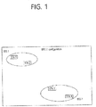
- FIG. 1 is a diagram showing an exemplary configuration of a wireless LAN (WLAN) system.
- WLAN wireless LAN
- a wireless LAN includes one or more Basic Service Set (BSS).
- BSS Basic Service Set
- a BSS is a set (or group) of stations (STAs) that successfully achieve synchronization so as to communication with one another.
- an STA As a logical entity including a Medium Access Control (MAC) and a Physical Layer interface for a wireless medium, an STA includes an access point (AP) and a non-AP Station.
- a portable device (or terminal) that is operated by a user corresponds to a non-AP Station.
- the STA may also refer to a non-AP Station.
- the non-AP Station may also be referred to as other terms, such as a terminal, a wireless transmit/receive unit (WTRU), a user equipment (UE), a mobile station (MS), a mobile terminal, a mobile subscriber unit, and so on.
- the AP is an entity providing its associated station (STA) with an access to a distribution system (DS) through a wireless medium.
- STA station
- DS distribution system
- the AP may also be referred to as a centralized controller, a base station (B), a Node-B, a base transceiver system (BTS), a personal basic service set central point/access point (PCP/AP), a site controller, and so on.
- a BSS may be categorized as an infrastructure BSS and an independent BSS (IBSS).
- IBSS independent BSS
- the BSS shown in FIG. 1 corresponds to an IBSS.
- the IBSS refers to a BSS that does not include an AP. And, since the BSS does not include an AP, access to the DS is not authorized (or approved), and, therefore, the IBSS functions as a self-contained network.
- FIG. 2 is a diagram showing another exemplary configuration of a wireless LAN (WLAN) system.
- WLAN wireless LAN
- the BSS shown in FIG. 2 corresponds to an infrastructure BSS.
- the infrastructure BSS includes one or more STAs and APs.
- STAs STAs
- APs APs.
- direct communication may also be established between the non-AP STAs.
- a plurality of infrastructure BSSs may be interconnected to one another through the DS.
- the plurality of BSSs being interconnected to one another through the DS is collectively referred to as an extended service set (ESS).
- the STAs being included in the ESS may perform communication between one another, and, a non-AP STA may shift (or relocate) from one BSS to another BSS within the same ESS while performing uninterrupted communication.
- the DS is not necessarily required to correspond to a network.
- the DS is capable of providing a predetermined distribution service, there is no limitation in the structure or configuration of the DS.
- the DS may correspond to a wireless network, such as a mesh network, or the DS may correspond to a physical structure (or entity) that connects the APs to one another.
- FIG. 3 is a diagram describing a channel in a 60GHz band for describing a channel bonding operation according to an exemplary embodiment of the present invention.
- 4 channels may be configured in a 60GHz band, and a general channel bandwidth may be equal to 2.16GHz.
- An ISM band (57 GHz ⁇ 66 GHz), which is available for usage in 60GHz, may be differently regulated in accordance with the circumstances (or situations) of each country.
- Channel 2 since Channel 2 is available for usage is all regions, Channel 2 may be used as a default channel.
- Channel 2 and Channel 3 may be used is most regions excluding Australia. And, accordingly, Channel 2 and Channel 3 may be used for channel bonding.
- diverse channels may be used for channel bonding. And, therefore, the present invention will not be limited to only one or more specific channels.
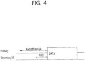
- FIG. 4 is a diagram describing a basic method for performing channel bonding in a wireless LAN (WLAN) system.
- WLAN wireless LAN
- the example shown in FIG. 4 corresponds to an example of combining two 20MHz channels and operating (or using) the combined channels for 40MHz channel bonding in an IEEE 802.11n system.
- 40/80/160 MHz channel bonding may be performed.
- the two exemplary channels of FIG. 4 include a primary channel and a secondary channel, and the STA may examine the channel status of the primary channel, among the two channels, by using a CSMA/CA method. If the primary channel is idle during a constant backoff interval, and, at a time point where the backoff count is equal to 0, if the secondary channel is idle during a predetermined period of time (e.g., PIFS), the STA may transmit data by combining the primary channel and the secondary channel.
- a CSMA/CA method e.g., a predetermined period of time
- a solution (or method) for performing scheduling-based access by having the AP transmit scheduling information to the STAs is proposed.
- a solution (or method) for performing contention-based channel access based on the above-described scheduling or independently from the above-described scheduling is proposed.
- a method for performing communication through a spatial sharing technique based on beamforming is proposed.
- FIG. 5 is a diagram describing a configuration of a beacon interval.
- the time of medium may be divided into beacon intervals.
- a lower level period within the beacon interval may be referred to as an access period.
- Each of the different access periods within one beacon interval may have a different access rule.
- Such information on the access period may be transmitted by an AP or personal basic service set control point (PCP) to a non-AP STA or non-PCP.
- PCP personal basic service set control point
- one beacon interval may include one Beacon Header Interval (BHI) and one Data Transfer Interval (DTI).
- BHI may include a Beacon Transmission Interval (BTI), an Association Beamforming Training (A-BFT), and an Announcement Transmission Interval (ATI).
- BTI Beacon Transmission Interval
- A-BFT Association Beamforming Training
- ATI Announcement Transmission Interval
- the BTI refers to a period (or section or duration) during which one more DMG beacon frames may be transmitted.
- the A-BFT refers to a period during which beamforming training is performed by an STA, which has transmitted a DMG beacon frame during a preceding BTI.
- the ATI refers to a request-response based management access period between PCP/AP and non-PCP/non-AP STA.
- the Data Transfer Interval refers to a period during which a frame exchange is performed between the STAs.
- one or more Contention Based Access Periods (CBAPs) and one or more Service Periods (SPs) may be allocated (or assigned) to the DTI.
- CBAPs Contention Based Access Periods
- SPs Service Periods
- FIG. 5 shows an example where 2 CBAPs and 2 SPs are allocated to the DCI, this is merely exemplary. And, therefore, the present invention is not necessarily required to be limited only to this.
- WLAN wireless LAN
- the wireless LAN (WLAN) system may provide 3 different modulations mode as shown below.
- PHY MCS Note Control PHY 0 Single carrier PHY 1...12 (low power SC PHY) (SC PHY) 25...31 OFDM PHY 13...24
- modulation modes may be used for satisfying different requirements (e.g., high throughput or stability).
- requirements e.g., high throughput or stability.
- modulation modes presented above only some of the modulation modes may be supported.
- FIG. 6 is a diagram describing a physical configuration of a legacy radio frame.
- DMG Directional Multi-Gigabit
- a preamble of a radio frame may include a Short Training Field (STF) and a Channel Estimation (CE). Additionally, the radio frame may also include a header and a data field as a payload of the radio frame and may optionally include a training (TRN) field for beamforming.
- STF Short Training Field
- CE Channel Estimation
- TRN training field
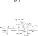
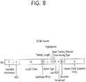
- FIG. 7 and FIG. 8 are diagrams describing a configuration of a header field of the radio frame shown in FIG. 6 .
- FIG. 7 illustrates a case where a Single Carrier (SC) mode is used.
- the header may include information indicating an initial value of scrambling, information indicating a Modulation and Coding Scheme (MCS) and a data length, information indicating the presence or absence of an additional Physical Protocol Data Unit (PPDU), and information on a packet type, a training length, aggregation or non-aggregation, a presence or absence of a beam training request, a last Received Signal Strength Indicator (RSSI), truncation or non-truncation, a Header Check Sequence (HCS), and so on.
- the header has 4 bits of reserved bits, and, in the description presented below, such reserved bits may also be used.
- FIG. 8 illustrates a detailed configuration of a header corresponding to a case where the OFDM mode is applied.
- the header may include information indicating an initial value of scrambling, information indicating a MCS and a data length, information indicating the presence or absence of an additional PPDU, and information on a packet type, a training length, aggregation or non-aggregation, a presence or absence of a beam training request, a last RSSI, truncation or non-truncation, a Header Check Sequence (HCS), and so on.
- the header has 2 bits of reserved bits, and, just as int he case of FIG. 7 , in the description presented below, such reserved bits may also be used.
- the IEEE 802.11ay system considers for the first time the adoption of channel bonding the MIMO technique to the legacy 11ad system.
- the 11ay system requires a new PPDU structure.
- the legacy 11ad PPDU structure there are limitations in supporting the legacy user equipment (UE) and implementing channel bonding and MIMO at the same time.
- a new field for the 11ay UE may be defined after the legacy preamble and legacy header field for supporting the legacy UE.
- channel bonding and MIMO may be supported by using the newly defined field.
- FIG. 9 is a diagram showing a PPDU structure according to a preferred embodiment of the present invention.
- a horizontal axis may correspond to a time domain
- a vertical axis may correspond to a frequency domain.
- a frequency band having a predetermined size may exist between a frequency band (e.g., 1.83GHz) that is used between each channel.
- a legacy preamble (legacy STF, legacy CE) is duplicated through each channel.
- it may be considered to perform the transmission (gap filling) of a new STF and CE field along with the legacy preamble at the same time through the 400MHz band between each channel.
- the PPDU structure according to the present invention has a structure of transmitting ay STF, ay CE, ay Header B, and ay payload after legacy preamble, legacy header, and ay Header A via wideband. Therefore, the ay Header and ay Payload fields, which are transmitted after the Header field, may be transmitted through the channels that are used for the channel bonding.
- the ay Header may be referred to as an enhanced directional multi-gigabit (EDMG) Header, and the corresponding terms may be used interchangeably.
- EDMG enhanced directional multi-gigabit
- a total of 6 channels or 8 channels may exist in the 11ay system, and a maximum of 4 channels may be bonded and transmitted to a single STA. Accordingly, the ay header and the ay Payload may be transmitted through bandwidths of 2.16GHz, 4.32GHz, 6.48GHz, and 8.64GHz.
- a PPDU format of a case where the legacy preamble is repeatedly transmitted without performing the above-described gap-filling may also be considered.
- the PPDU has a format of transmitting the ay STF, ay CE, and ay Header B after the legacy preamble, legacy header, and ay Header A without the GF-STF and GF-CE fields, which are illustrated in dotted lines in FIG. 8 .
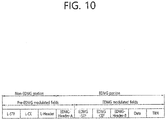
- FIG. 10 is a diagram showing a simple PPDU structure that can be applied to the present invention.
- the PPDU format may be illustrated as shown in FIG. 10 .
- the PPDU format that is applicable to the 11ay system may include L-STF, L-CEF, L-Header, EDMG-Header-A, EDMG-STF, EDMG-CEF, EDMG-Header-B, Data, and TRN fields, and the above-mentioned fields may be selectively included in accordance with the format of the PPDU (e.g., SU PPDU, MU PPDU, and so on).
- the format of the PPDU e.g., SU PPDU, MU PPDU, and so on.
- the part (or portion) including the L-STF, L-CEF, and L-header fields may be referred to as a Non-EDMG portion, and the remaining part (or portion) may be referred to as an EDMG portion (or region).
- the L-STF, L-CEF, L-Header, and EDMG-Header-A fields may be referred to as pre-EDMG modulated fields, and the remaining fields may be referred to as EDMG modulated fields.
- the preamble is a part of the PPDU that is used for packet detection, AGC, frequency offset estimation, synchronization, indication of modulation (SC or OFDM) and channel estimation.
- the format of the preamble is common to both OFDM packets and SC packets.
- the preamble is configured of two parts: the Short Training field and the Channel Estimation field).
- the TRN subfield for EDMG OFDM PPDU may be configured by using/based on the EDMG CEF in the OFDM mode or EDMG STF in the OFDM mode.
- the TRN subfield for EMDG OFDM PPDU may be configured by using/based on a sequence with good PAPR performance.
- the structure of the EDMG-CEF field depends on the number of contiguous 2.16 GHz channels through which an EDMG PPDU is transmitted and the number, i STS , of space-time streams.
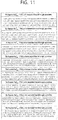
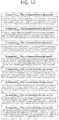
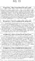
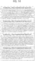
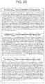
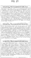
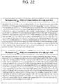
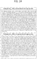
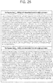
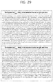
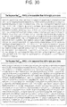
- N iSTS and Seq right , N iSTS sequences of length N used for definition of the EDMG-CEF field are defined as shown in FIGs. 11 to 30 depending on the value of N.
- N may have one of the values 176, 385, 595, and 804.
- FIG. 11 illustrates Seq left , 176 iSTS per space-time stream
- FIG. 12 illustrates Seq right , 176 iSTS per space-time stream.
- FIGs. 13 and 14 illustrate Seq left , 385 iSTS per space-time stream; and FIGs. 15 and 16 illustrate Seq right , 385 iSTS per space-time stream.
- FIGs. 17 to 19 illustrate Seq left , 595 iSTS per space-time stream; and FIGs. 20 to 22 illustrate Seq right , 595 iSTS per space-time stream.
- FIGs. 23 to 26 illustrate Seq left , 804 iSTS per space-time stream; and FIGs. 27 to 30 illustrate Seq right , 804 iSTS per space-time stream.
- the EDMG-CEF sequence in the frequency domain for the i-th space-time stream may be defined by the equation below.
- Seq left , 176 iSTS and Seq right , 176 iSTS may be defined as shown in FIGs. 11 and 12 .
- the EDMG-CEF sequence in the frequency domain for the i-th space-time sequence may be defined by the equation below.
- Seq left , 385 iSTS and Seq right , 385 iSTS may be defined as shown in FIGs. 13 to 16 .
- the EDMG-CEF sequence in the frequency domain for the i-th space-time sequence may be defined by the equation below.
- Seq left , 595 iSTS and Seq right , 595 iSTS may be defined as shown in FIGs. 17 to 22 .
- the EDMG-CEF sequence in the frequency domain for the i-th space-time sequence may be defined by the equation below.
- Seq left , 804 iSTS and Seq right , 804 iSTS may be defined as shown in FIGs. 23 to 30 .
- transmit waveform of the EDMG-CEF field in the time domain may be defined by the equation given below.
- N CB represents/is the number of contiguous or bonded (or combined) channels.
- N E ⁇ D ⁇ M ⁇ G ⁇ - ⁇ CEF Tone N ST ⁇ N DC is the total number of active tones
- the TRN subfield in the SC mode may have a TRN subfield sequence having a different length depending on the value of TRN_BL.
- the TRN_BL value may be configured differently according to the 'TRN Subfield Sequence Length field' value of the EDMG Header-A field.
- TRN_BL is set to 128; when the TRN Subfield Sequence Length field of the EDMG-Header-A is 1, TRN_BL is set to 256; and when the TRN Subfield Sequence Length field of the EDMG-Header-A is 2, TRN_BL is set to 64.
- TRN Subfield Sequence Length field of the EDMG-Header-A is 0, it may indicate 'Normal' while, when it is 2, it may indicate 'Short'.
- the TRN sequence in the SC mode may be configured of 6 Golay complementary sequences Ga and Gb as shown in the equation given below.
- TRN i basic Ga i N , ⁇ Gb i N , Ga i N , Gb i N , Ga i N , ⁇ Gb i N
- i may represent a space-time stream or a transmit chain.
- the length of the TRN subfield may be configured differently depending on the TRN Subfield Sequence Length field of the EDMG Header-A. Accordingly, duration of a TRN subfield sequence for each case may be determined as follows.
- T C denotes a chip rate of the SC mode and may be 0.57 ns.
- the 802.11ay system to which the present invention may be applied may support signal transmission and reception through a channel bonded with one to four channels. Therefore, according to the number of bonded channels, a basic OFDM TRN subfield, an OFDM TRN subfield corresponding to one OFDM symbol, which may be applied to the present invention may be composed as follows.
- the sample frequency F S in the OFDM mode is 2.64 GHz
- a transmitter applies a 512-point Inverse Discrete Fourier Transform (IDFT) on the OFDM EDMG-CEF and inserts cyclic prefix to compose the OFDM TRN subfield.
- IDFT Inverse Discrete Fourier Transform
- the length of the inserted CP (or the number of samples) may correspond to 48, 96, 192, 32, 64, or 128 samples.
- the total number of samples for one OFDM symbol may be 560, 608, 704, 544, 576, or 640.
- the length of each TRN subfield in the time domain may be 560 ⁇ T S , 608 ⁇ T S , 704 ⁇ T S , 544 ⁇ T S , 576 ⁇ T S , or 640 ⁇ T S .
- the sample frequency F S in the OFDM mode is 5.28 GHz
- a transmitter applies a 512-point IDFT on the OFDM EDMG-CEF and inserts cyclic prefix to compose the OFDM TRN subfield.
- the length of the inserted CP (or the number of samples) may correspond to 96, 192, 384, 64, 128, or 256 samples.
- the total number of samples for one OFDM symbol may be 1120, 1216, 1408, 1088, 1152, or 1280.
- the length of each TRN subfield in the time domain may be 1120 ⁇ T S , 1216 ⁇ T S , 1408 ⁇ T S , 1088 ⁇ T S , 1152 ⁇ T S , or 1280 ⁇ T S .
- the sample frequency F S in the OFDM mode is 7.92 GHz
- a transmitter applies a 512-point IDFT on the OFDM EDMG-CEF and inserts cyclic prefix to compose the OFDM TRN subfield.
- the length of the inserted CP (or the number of samples) may correspond to 144, 288, 576, 96, 192, or 384 samples.
- the total number of samples for one OFDM symbol may be 1680, 1824, 2112, 1632, 1728, or 1920.
- the length of each TRN subfield in the time domain may be 1680 ⁇ T S , 1824 ⁇ T S , 2112 ⁇ T S , 1632 ⁇ T S , 1728 ⁇ T S , or 1920 ⁇ T S .
- the sample frequency F S in the OFDM mode is 10.56 GHz
- a transmitter applies a 2018-point IDFT on the OFDM EDMG-CEF and inserts cyclic prefix to compose the OFDM TRN subfield.
- the length of the inserted CP (or the number of samples) may correspond to 192, 384, 768, 128, 256, or 512 samples.
- the total number of samples for one OFDM symbol may be 2240, 2432, 2816, 2176, 2304, or 2560.
- the length of each TRN subfield in the time domain may be 2240 ⁇ T S , 2432 ⁇ T S , 2816 ⁇ T S , 2176 ⁇ T S , 2304 ⁇ T S , or 2560 ⁇ T S .
- the transmitter may compose an OFDM TRN subfield corresponding to one OFDM symbol by using the CP+IDFT (OFDM EDMG-CEF) structure according to/based on the total number of CP samples described above.
- OFDM EDMG-CEF CP+IDFT
- Header-A field of an EDMG OFDM PPDU may include a field (for example, TRN Subfield Sequence Length field) indicating the length of a TRN field.
- TRN Subfield Sequence Length field indicating the length of a TRN field.
- the TRN subfield according to the value of the aforementioned field may be configured of repeating the basic TRN subfield (CP + IDFT (OFDM EDMG-CEF)) one to five times. Therefore, in what follows, similarly to the SC mode, a TRN subfield structure (for example, symbol length of the TRN subfield) which may be applied according to the 'TRN Subfield Sequence Length field' value of the EMDG Header-A field will be described in detail.
- CP + IDFT OFDM EDMG-CEF
- FIG. 31 illustrates a TRN subfield structure corresponding to one OFDM symbol.
- the corresponding TRN subfield structure may be configured of a TRN subfield structure corresponding to one OFDM symbol (namely a structure configured of one basic OFDM TRN subfield).
- FIGs. 32 and 33 illustrate a TRN subfield structure corresponding two OFDM symbols.
- the corresponding TRN subfield structure may be configured of a TRN subfield structure corresponding to two OFDM symbols (namely a structure configured of two basic OFDM TRN subfields).
- CP may be used twice as shown in FIG. 32 , or only one CP may be used over two OFDM symbols as shown in FIG. 33 .
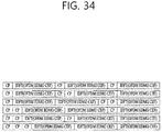
- FIG. 34 illustrates a TRN subfield structure corresponding to three OFDM symbols.
- the corresponding TRN subfield structure may be configured of a TRN subfield structure corresponding to three OFDM symbols (namely a structure configured of three basic OFDM TRN subfields).
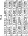
- FIGs. 35 and 36 illustrate a TRN subfield structure corresponding to four OFDM symbols.
- the corresponding TRN subfield structure may be configured of a TRN subfield structure corresponding to four OFDM symbols (namely a structure configured of four basic OFDM TRN subfields).
- CP may be used four times for each symbol as shown in FIG. 35 , or only two CPs may be used over four OFDM symbols as shown in FIG. 36 .
- the corresponding TRN subfield may be configured of a TRN subfield structure corresponding to one OFDM symbol (namely a structure configured of one basic OFDM TRN subfield), a TRN subfield structure corresponding to two OFDM symbols (namely a structure configured of two basic OFDM TRN subfields), a TRN subfield structure configured of three OFDM symbols (namely a structure configured of three basic OFDM TRN subfields), or a TRN subfield structure corresponding to four OFDM symbols (namely a structure configured of four basic OFDM TRN subfields).
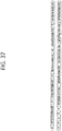
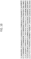
- TRN Subfield Sequence Length field of the EDMG-Header-A is 1, as shown in FIG. 37 or 38 , the corresponding TRN subfield may be configured of a TRN subfield structure corresponding to five or six OFDM symbols.
- FIG. 37 illustrates a TRN subfield structure corresponding to five OFDM symbols.
- the corresponding TRN subfield structure may be configured of a TRN subfield structure corresponding to five OFDM symbols (namely a structure configured of five basic OFDM TRN subfields).
- FIG. 38 illustrates a TRN subfield structure corresponding to six OFDM symbols.
- the corresponding TRN subfield structure may be configured of a TRN subfield structure corresponding to six OFDM symbols (namely a structure configured of six basic OFDM TRN subfields).
- the corresponding TRN subfield may be configured of a TRN subfield structure corresponding to one OFDM symbol (namely a structure configured of one basic OFDM TRN subfield) or a TRN subfield structure corresponding to two OFDM symbols (namely a structure configured of two basic OFDM TRN subfields).
- a TRN subfield structure according to the value of the TRN Subfield Sequence Length field of the EDMG Header-A field (namely a structure where the basic TRN subfield structure is repeated for a predetermined number of times) may be determined so as to be aligned with the TRN subfield of the SC mode in the time domain.
- the TRN subfield of the OFDM mode corresponding to the normal case may be configured of/may include one OFDM symbol (704 ⁇ T S when a long Guard Interval (GI) with a length of 72.72 ns is used) or two OFDM symbols (1408 ⁇ T S when a long Guard Interval (GI) with a length of 72.72 ns is used).
- GI Guard Interval
- the TRN subfield structure in the normal case may be configured of two OFDM symbols.
- the TRN subfield may be configured of a TRN subfield structure corresponding to two OFDM symbols as shown in FIG. 32 ; if the TRN subfield Sequence Length field of the EDMG-Header-A is 1, the TRN subfield may be configured of a TRN subfield structure corresponding to four OFDM symbols as shown in FIG. 35 ; and if the TRN subfield Sequence Length field of the EDMG-Header-A is 0, the TRN subfield may be configured of a TRN subfield structure corresponding to one OFDM symbols as shown in FIG. 31 .
- time duration of the TRN subfield of the OFDM mode may be aligned with that of the TRN subfield of the SC mode in the time domain.
- 512-point IDFT may be applied; in the case of 2 channel bonding, 1024-point IDFT; in the case of 3 channel bonding, 1536-point IDFT; and in the case of 4 channel bonding, 2048-point IDFT.
- the number of CP samples which may be applied is 48, 96, 192, 32, 64, or 128 for the case of single channel bonding; 96, 192, 384, 64, 128, or 256 for the case of 2 channel bonding; 144, 288, 576, 96, 192, or 384 for the case of 3 channel bonding; and 192, 384, 768, 128, 256, or 512 for the case of 4 channel bonding.
- the order of CP and IDFT may be changed in various ways.
- the 11ay system applicable for the present invention may support up to 8 space-time streams to support the Multiple Input Multiple Output scheme.
- OFDM TRN subfield structure according to/based on the total number of supported streams will be described in detail.
- a signal obtained by repeating the TRN subfield structure, which corresponds to one OFDM symbol obtained through insertion of CP after IDFT is applied to the OFDM EDMG-CEF of the i-th space-time stream, one, two, or four times according to the value of the TRN Subfield Sequence Length field of the EDMG-Header-A is denoted as OFDM_TRN_basic_i.
- the OFDM TRN subfield according to/based on the total number of space time streams may be defined as follows.
- the TRN field transmitted by the transmitter may be determined to have a different length according to/based on the total number of streams to be transmitted and the value of the TRN Subfield Sequence Length field of the EDMG Header-A field.
- the TRN field (or TRN subfield) of the EDMG OFDM mode may be composed as follows.
- an OFDM TRN_BASIC sequence in the frequency domain for the iTX-th space-time stream may be defined by the equation given below.
- Seq iTX left, 176 and Seq iTX right, 176 may correspond to Seq i STS left , 176 and Seq i STS right , 176 of FIGs. 11 and 12 above.
- an OFDM TRN_BASIC sequence in the frequency domain for the iTX-th space-time stream may be defined by the equation given below.
- Seq iTX left, 385 and Seq iTX right, 385 may correspond to Seq i STS left , 385 and Seq i STS right , 385 of FIGs. 13 to 16 above.
- an OFDM TRN_BASIC sequence in the frequency domain for the iTX-th space-time stream may be defined by the equation given below.
- Seq iTX left, 595 and Seq iTX right, 595 may correspond to Seq i STS left , 595 and Seq i STS right , 595 of FIGs. 17 to 22 above.
- an OFDM TRN_BASIC sequence in the frequency domain for the i TX -th space-time stream may be defined by the equation given below.
- Seq iTX left, 804 and Seq iTX right, 804 may correspond to Seq i STS left , 804 and Seq i STS right , 804 of FIGs. 23 to 30 above.
- a basic OFDM TRN subfield waveform for the i TX -th transmission chain (or space-time stream) in the time domain may be defined by the equation given below.
- ⁇ k ⁇ N SR N SR P TRN i TX .
- n TRN _ BASIC k i TX exp j 2 ⁇ k ⁇ F qT s ⁇ T GI long , 1 ⁇ n ⁇ N TRN N TX
- the Normal TRN subfield, Short TRN subfield, and Long TRN subfield according to the value of the TRN Subfield Sequence Length field of the EDMG Header-A field may be defined by the equation given below.
- r TRN _ BASIC i TX qT s ⁇ n ⁇ 1 ⁇ T BASIC
- P TRN (OFDM TRN mapping matrix) may be defined according to the N TX value by the equation given below.
- N TRN N TX 3
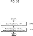
- FIG. 39 illustrates a method for transmitting signals including a TRN field according to one embodiment of the present invention.
- a transmitter for example, STA
- STA generates a training field included in a signal to be transmitted S3910.
- the transmitter may generate a training field including a training subfield per space-time stream based on a basic training subfield per space-time stream and the total number of space-time streams.
- the basic training subfield per space-time stream may be configured of M (where M is a natural number) Orthogonal Frequency Division Multiplexing (OFDM) symbols based on information indicated by/included in a header field.
- OFDM Orthogonal Frequency Division Multiplexing
- the training field includes a training subfield per space-time stream
- the training subfield per space-time stream may be configured by using/based on the basic training subfield per space-time stream based on a rule determined according to/based on the total number of space-time streams.
- the training subfield per space-time stream may be composed as follows.
- OFDM_TRN_subfield_N represents/is a training subfield for a space-time stream for an index N
- OFDM_TRN_basic_N represents/is a basic training subfield for the space-time stream for an index N.
- OFDM _ TRN _ subfield _ 1 OFDM _ TRN _ basic _ 1
- the training subfield per space-time stream may be composed as follows.
- ⁇ OFDM _ TRN _ subfield _ 1 OFDM _ TRN _ basic _ 1
- ⁇ OFDM _ TRN _ subfield _ 2 OFDM _ TRN _ basic _ 2
- OFDM _ TRN _ basic _ 2 OFDM _ TRN _ basic _ 2
- the training subfield per space-time stream may be composed as follows.
- w 3 exp(-j ⁇ 2 ⁇ pi/3).
- the training subfield per space-time stream may be composed as follows.
- the training subfield per space-time stream may be composed as follows.
- w 6 exp(-j ⁇ 2 ⁇ pi/6).
- the training subfield per space-time stream may be composed as follows.
- the training subfield per space-time stream may be composed as follows.
- the training subfield per space-time stream may be composed as follows.
- the basic training subfield per space-time stream may be configured of/may include one, two, or four OFDM symbols based on the information indicated by/included in the header field.
- one OFDM symbol included in the one, two, or four OFDM symbols may include a guard interval with a length of 72.72 ns or cyclic prefix (CP).
- CP cyclic prefix
- the header field may include an Enhanced Directional Multi Gigabit (EDMG) training subfield sequence length field which indicates/including information on the OFDM symbol length of the basic training subfield per space-time stream.
- EDMG Enhanced Directional Multi Gigabit
- the basic training subfield per space-time stream may be configured of two OFDM symbols; when the EDMG training subfield sequence length field indicates 1, the basic training subfield per space-time stream may be configured of four OFDM symbols; and when the EDMG training subfield sequence length field indicates 2, the basic training subfield per space-time stream may be configured of/may include one OFDM symbol.
- the basic training subfield per space-time stream may be configured of/may include a sequence with a different length in the frequency domain according to the number of contiguous channels through which the signal is transmitted.
- the basic training subfield per space-time stream may be configured of/may include a sequence with a length of 355 in the frequency domain. At this time, a 512-point IDFT may be applied to the sequence.
- the basic training subfield per space-time stream may be configured of/may include a sequence with a length of 773 in the frequency domain. At this time, a 1024-point IDFT may be applied to the sequence.
- the basic training subfield per space-time stream may be configured of/may include a sequence with a length of 596 in the frequency domain. At this time, a 1536-point IDFT may be applied to the sequence.
- the basic training subfield per space-time stream may be configured of/may include a sequence with a length of 805 in the frequency domain. At this time, a 2048-point IDFT may be applied to the sequence.
- the transmitter transmits a signal including the training field generated as above and the header field to a receiver through the corresponding space-time stream S3920.
- the transmitter may transmit the signal through the corresponding space-time stream within a plurality of channels.
- the receiver receives a header field included in the transmitted signal.
- the receiver determines the number of Orthogonal Frequency Division Multiplexing (OFDM) symbols of a basic training subfield per space-time stream based on the information indicated by/included in the header field.
- the receiver receives a training field including a training subfield per space-time stream configured based on the basic training subfield per space-time stream configured of the total number of space-time streams and the number of determined OFDM symbols, through the corresponding space-time stream.
- OFDM Orthogonal Frequency Division Multiplexing
- the receiver may perform channel measurement in the frequency domain during a symbol period through which the training field is transmitted through the training field.
- training subfields for the respective space-time streams may be kept mutually orthogonal to each other.
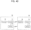
- FIG. 40 is a diagram illustrating a device for implementing the above-described method.
- a wireless device 100 of FIG. 40 may correspond to an STA that transmits a signal described in the above description, and a wireless device 150 may correspond to an STA that receives a signal described in the above description.
- the station transmitting the signal may correspond to a PCP/AP or an 11ay terminal supporting an 11ay system
- the station receiving the signal may correspond to a legacy terminal (e.g., 11ad terminal) that does not support the 11ay system as well as a PCP/AP or an 11ay terminal supporting the 11ay system.
- the STA transmitting a signal is referred to as a transmitting device 100
- the STA receiving a signal is referred to as a receiving device 150.
- the transmitting device (100) may include a processor (110), a memory (120), and a transmitting/receiving unit (130), and the receiving device (150) may include a processor (160), a memory (170), and a transmitting/receiving unit (180).
- the transmitting/receiving unit (130, 180) transmits/receives a radio signal and may be operated in a physical layer of IEEE 802.11/3GPP, and so on.
- the processor (110, 160) may be operated in the physical layer and/or MAC layer and may be operatively connected to the transmitting/receiving unit (130, 180).
- the processor (110, 160) and/or the transmitting/receiving unit (130, 180) may include application-specific integrated circuit (ASIC), other chipset, logic circuit and/or data processor.
- the memory (120, 170) may include read-only memory (ROM), random access memory (RAM), flash memory, memory card, storage medium and/or other storage unit.
- ROM read-only memory
- RAM random access memory
- flash memory memory card
- storage medium storage medium and/or other storage unit.
- modules can be stored in the memory (120, 170) and executed by the processor (110, 160).
- the memory (120, 170) can be implemented (or positioned) within the processor (110, 160) or external to the processor (110, 160). Also, the memory (120, 170) may be operatively connected to the processor (110, 160) via various means known in the art.
- the present invention has been described in detail under the assumption that the present invention can be applied to an IEEE 802.11 based wireless LAN (WLAN) system, the present invention will not be limited only to this. It will be understood that the present invention can be applied to diverse wireless systems capable of performing data transmission based on channel bonding by using the same method as presented herein.
- WLAN wireless local area network
Landscapes
- Engineering & Computer Science (AREA)
- Signal Processing (AREA)
- Computer Networks & Wireless Communication (AREA)
- Mobile Radio Communication Systems (AREA)
- Radio Transmission System (AREA)
Applications Claiming Priority (3)
| Application Number | Priority Date | Filing Date | Title |
|---|---|---|---|
| US201762531446P | 2017-07-12 | 2017-07-12 | |
| US201762535242P | 2017-07-21 | 2017-07-21 | |
| PCT/KR2018/004125 WO2019013431A1 (ko) | 2017-07-12 | 2018-04-09 | 무선랜 시스템에서 신호의 송수신 방법 및 이를 위한 장치 |
Publications (3)
| Publication Number | Publication Date |
|---|---|
| EP3567821A1 true EP3567821A1 (de) | 2019-11-13 |
| EP3567821A4 EP3567821A4 (de) | 2020-04-08 |
| EP3567821B1 EP3567821B1 (de) | 2021-06-23 |
Family
ID=65002655
Family Applications (1)
| Application Number | Title | Priority Date | Filing Date |
|---|---|---|---|
| EP18831802.6A Active EP3567821B1 (de) | 2017-07-12 | 2018-04-09 | Verfahren zum senden oder empfangen eines signals in einem wlan-system und vorrichtung dafür |
Country Status (7)
| Country | Link |
|---|---|
| US (2) | US10659974B2 (de) |
| EP (1) | EP3567821B1 (de) |
| JP (1) | JP7130730B2 (de) |
| KR (1) | KR102075771B1 (de) |
| CN (1) | CN110999240B (de) |
| BR (1) | BR112020000669A2 (de) |
| WO (1) | WO2019013431A1 (de) |
Families Citing this family (8)
| Publication number | Priority date | Publication date | Assignee | Title |
|---|---|---|---|---|
| US11108603B2 (en) * | 2016-10-10 | 2021-08-31 | Qualcomm Incorporated | Frame format with dual mode channel estimation field |
| WO2018175722A1 (en) * | 2017-03-23 | 2018-09-27 | Intel IP Corporation | Apparatus, system and method of communicating an edmg ppdu |
| US10659974B2 (en) * | 2017-07-12 | 2020-05-19 | Lg Electronics Inc. | Method for transmitting and receiving signal in wireless LAN system, and apparatus therefor |
| US10904062B2 (en) * | 2017-08-08 | 2021-01-26 | Intel Corporation | Apparatus, system and method of communicating a physical layer protocol data unit (PPDU) including a training field |
| CN111934736B (zh) * | 2017-08-31 | 2024-04-26 | 华为技术有限公司 | 一种发送波束优化协议包的方法及设备 |
| US10707993B2 (en) * | 2018-08-23 | 2020-07-07 | Sr Technologies, Inc. | Blind detection and synchronization of data packets |
| CN112821998A (zh) * | 2019-11-15 | 2021-05-18 | 华为技术有限公司 | 传输物理层协议数据单元的方法和装置 |
| CN120883578A (zh) * | 2023-03-21 | 2025-10-31 | 华为技术有限公司 | 用于高效ofdm通信的设备和方法 |
Family Cites Families (26)
| Publication number | Priority date | Publication date | Assignee | Title |
|---|---|---|---|---|
| US8085871B2 (en) * | 2005-04-21 | 2011-12-27 | Broadcom Corporation | Adaptive modulation in a multiple input multiple output wireless communication system with optional beamforming |
| US8553730B2 (en) * | 2009-08-31 | 2013-10-08 | Texas Instruments Incorporated | Short and long training fields |
| EP2471200A4 (de) * | 2009-12-10 | 2012-10-17 | Lg Electronics Inc | Verfahren und vorrichtung zur übertragung von trainingssignalen in einem wlan-system |
| KR101801943B1 (ko) * | 2010-02-25 | 2017-11-27 | 한국전자통신연구원 | 다중 사용자 다중 안테나 기반 무선 통신 시스템에서 훈련 시퀀스 전송 방법 및 그 장치 |
| JP6190889B2 (ja) | 2012-11-09 | 2017-08-30 | インターデイジタル パテント ホールディングス インコーポレイテッド | ビーム形成方法およびビームを使用するための方法 |
| AU2015304131B2 (en) * | 2014-08-21 | 2018-08-02 | Lg Electronics Inc. | Method for uplink transmission in wireless communication system and apparatus therefor |
| EP3198817B8 (de) * | 2014-09-23 | 2020-04-01 | NXP USA, Inc. | Kurzes trainingsfeld für wifi |
| US10044635B2 (en) | 2014-12-09 | 2018-08-07 | Qualcomm Incorporated | Frame formats for channel bonding and MIMO transmissions |
| US10050750B2 (en) * | 2014-12-09 | 2018-08-14 | Qualcomm Incorporated | Training field tone plans for mixed-rate wireless communication networks |
| US10327226B2 (en) * | 2014-12-12 | 2019-06-18 | Newracom, Inc. | Method and apparatus for resource allocation for multiple user transmission in a High Efficiency wireless LAN |
| US11317260B2 (en) * | 2015-01-27 | 2022-04-26 | Telefonaktiebolaget Lm Ericsson (Publ) | Methods and arrangements for WLAN communication of multi-user data in a single data packet |
| US20160261319A1 (en) | 2015-03-05 | 2016-09-08 | Qualcomm Incorporated | Channel estimation for bonded channels |
| US9655112B2 (en) * | 2015-04-30 | 2017-05-16 | Intel IP Corporation | Apparatus, system and method of communicating a wireless communication frame with a header |
| US9893785B2 (en) * | 2015-09-11 | 2018-02-13 | Intel IP Corporation | Enhanced beamforming training in a wireless local area networks |
| WO2017043912A1 (ko) * | 2015-09-11 | 2017-03-16 | 엘지전자 주식회사 | 무선랜 시스템에서의 신호 전송 방법 및 이를 위한 장치 |
| US10142005B2 (en) | 2015-11-02 | 2018-11-27 | Lg Electronics Inc. | Beamforming training |
| US11330465B2 (en) * | 2016-05-11 | 2022-05-10 | Huawei Technologies Co., Ltd. | Method and apparatus for indicating control information in a wireless frame |
| US20180014216A1 (en) * | 2016-07-11 | 2018-01-11 | Qualcomm Incorporated | Low power and long range preambles for a wireless local area network |
| US10243635B2 (en) * | 2016-07-22 | 2019-03-26 | Peraso Technologies Inc. | Method and apparatus for beamforming training using frames |
| CN109923841B (zh) * | 2016-11-04 | 2021-01-12 | 华为技术有限公司 | 一种参考信号配置方法、训练字段配置方法及装置 |
| CN106534030B (zh) * | 2016-11-29 | 2019-05-31 | 重庆邮电大学 | 一种基于802.11n多天线OFDM系统中联合训练序列和导频的信道估计方法 |
| US10727994B2 (en) | 2017-01-09 | 2020-07-28 | Qualcomm Incorporated | Using sequences of pilot repetitions for receiver adaptation |
| WO2018191033A1 (en) * | 2017-04-13 | 2018-10-18 | Intel Corporation | Enhanced training sub-field indexing for wireless communications |
| KR102225545B1 (ko) | 2017-04-20 | 2021-03-09 | 엘지전자 주식회사 | 무선랜 시스템에서의 신호 송수신 방법 및 이를 위한 장치 |
| US10659974B2 (en) | 2017-07-12 | 2020-05-19 | Lg Electronics Inc. | Method for transmitting and receiving signal in wireless LAN system, and apparatus therefor |
| US10904062B2 (en) * | 2017-08-08 | 2021-01-26 | Intel Corporation | Apparatus, system and method of communicating a physical layer protocol data unit (PPDU) including a training field |
-
2018
- 2018-04-09 US US16/325,693 patent/US10659974B2/en active Active
- 2018-04-09 CN CN201880049044.XA patent/CN110999240B/zh active Active
- 2018-04-09 KR KR1020197003019A patent/KR102075771B1/ko active Active
- 2018-04-09 EP EP18831802.6A patent/EP3567821B1/de active Active
- 2018-04-09 JP JP2020501485A patent/JP7130730B2/ja active Active
- 2018-04-09 WO PCT/KR2018/004125 patent/WO2019013431A1/ko not_active Ceased
- 2018-04-09 BR BR112020000669-6A patent/BR112020000669A2/pt unknown
-
2020
- 2020-02-24 US US16/799,553 patent/US10993125B2/en active Active
Also Published As
| Publication number | Publication date |
|---|---|
| BR112020000669A2 (pt) | 2020-07-14 |
| US20190215702A1 (en) | 2019-07-11 |
| US20200196165A1 (en) | 2020-06-18 |
| US10659974B2 (en) | 2020-05-19 |
| JP7130730B2 (ja) | 2022-09-05 |
| KR20190020145A (ko) | 2019-02-27 |
| KR102075771B1 (ko) | 2020-02-10 |
| EP3567821A4 (de) | 2020-04-08 |
| US10993125B2 (en) | 2021-04-27 |
| JP2020526990A (ja) | 2020-08-31 |
| CN110999240A (zh) | 2020-04-10 |
| CN110999240B (zh) | 2022-06-24 |
| WO2019013431A1 (ko) | 2019-01-17 |
| EP3567821B1 (de) | 2021-06-23 |
Similar Documents
| Publication | Publication Date | Title |
|---|---|---|
| US11057255B2 (en) | Method for transmitting and receiving signals in wireless LAN system and apparatus therefor | |
| US10993125B2 (en) | Method for transmitting and receiving signal in wireless LAN system, and apparatus therefor | |
| US11265193B2 (en) | Method for transmitting and receiving signal in WLAN system and device therefor | |
| US11469932B2 (en) | Method for transmitting and receiving signal in wireless LAN system and apparatus for said method | |
| US11563523B2 (en) | Method of transmitting and receiving signals in WLAN system and device for the same | |
| US10840993B2 (en) | Method for transmitting and receiving signal in wireless LAN system and apparatus for said method | |
| EP3481023B1 (de) | Verfahren zum senden oder empfangen eines signals in einem wlan-system und vorrichtung dafür | |
| US10945301B2 (en) | Method for transmitting and receiving a signal based on a channel aggregation transmission in a wireless local access network system and devices supporting the same | |
| EP3579516B1 (de) | Verfahren zum senden oder empfangen eines signals in einem wlan-system und vorrichtung dafür |
Legal Events
| Date | Code | Title | Description |
|---|---|---|---|
| STAA | Information on the status of an ep patent application or granted ep patent |
Free format text: STATUS: THE INTERNATIONAL PUBLICATION HAS BEEN MADE |
|
| PUAI | Public reference made under article 153(3) epc to a published international application that has entered the european phase |
Free format text: ORIGINAL CODE: 0009012 |
|
| STAA | Information on the status of an ep patent application or granted ep patent |
Free format text: STATUS: REQUEST FOR EXAMINATION WAS MADE |
|
| 17P | Request for examination filed |
Effective date: 20190206 |
|
| AK | Designated contracting states |
Kind code of ref document: A1 Designated state(s): AL AT BE BG CH CY CZ DE DK EE ES FI FR GB GR HR HU IE IS IT LI LT LU LV MC MK MT NL NO PL PT RO RS SE SI SK SM TR |
|
| AX | Request for extension of the european patent |
Extension state: BA ME |
|
| A4 | Supplementary search report drawn up and despatched |
Effective date: 20200309 |
|
| RIC1 | Information provided on ipc code assigned before grant |
Ipc: H04L 5/00 20060101ALI20200303BHEP Ipc: H04L 1/06 20060101ALI20200303BHEP Ipc: H04W 16/28 20090101ALI20200303BHEP Ipc: H04B 7/06 20060101ALI20200303BHEP Ipc: H04L 27/26 20060101AFI20200303BHEP Ipc: H04L 1/00 20060101ALI20200303BHEP Ipc: H04W 84/12 20090101ALI20200303BHEP |
|
| DAV | Request for validation of the european patent (deleted) | ||
| DAX | Request for extension of the european patent (deleted) | ||
| GRAP | Despatch of communication of intention to grant a patent |
Free format text: ORIGINAL CODE: EPIDOSNIGR1 |
|
| STAA | Information on the status of an ep patent application or granted ep patent |
Free format text: STATUS: GRANT OF PATENT IS INTENDED |
|
| INTG | Intention to grant announced |
Effective date: 20210114 |
|
| GRAS | Grant fee paid |
Free format text: ORIGINAL CODE: EPIDOSNIGR3 |
|
| GRAA | (expected) grant |
Free format text: ORIGINAL CODE: 0009210 |
|
| STAA | Information on the status of an ep patent application or granted ep patent |
Free format text: STATUS: THE PATENT HAS BEEN GRANTED |
|
| AK | Designated contracting states |
Kind code of ref document: B1 Designated state(s): AL AT BE BG CH CY CZ DE DK EE ES FI FR GB GR HR HU IE IS IT LI LT LU LV MC MK MT NL NO PL PT RO RS SE SI SK SM TR |
|
| REG | Reference to a national code |
Ref country code: GB Ref legal event code: FG4D |
|
| REG | Reference to a national code |
Ref country code: CH Ref legal event code: EP |
|
| REG | Reference to a national code |
Ref country code: DE Ref legal event code: R096 Ref document number: 602018019126 Country of ref document: DE Ref country code: AT Ref legal event code: REF Ref document number: 1405282 Country of ref document: AT Kind code of ref document: T Effective date: 20210715 |
|
| REG | Reference to a national code |
Ref country code: IE Ref legal event code: FG4D |
|
| REG | Reference to a national code |
Ref country code: LT Ref legal event code: MG9D |
|
| PG25 | Lapsed in a contracting state [announced via postgrant information from national office to epo] |
Ref country code: FI Free format text: LAPSE BECAUSE OF FAILURE TO SUBMIT A TRANSLATION OF THE DESCRIPTION OR TO PAY THE FEE WITHIN THE PRESCRIBED TIME-LIMIT Effective date: 20210623 Ref country code: LT Free format text: LAPSE BECAUSE OF FAILURE TO SUBMIT A TRANSLATION OF THE DESCRIPTION OR TO PAY THE FEE WITHIN THE PRESCRIBED TIME-LIMIT Effective date: 20210623 Ref country code: HR Free format text: LAPSE BECAUSE OF FAILURE TO SUBMIT A TRANSLATION OF THE DESCRIPTION OR TO PAY THE FEE WITHIN THE PRESCRIBED TIME-LIMIT Effective date: 20210623 Ref country code: BG Free format text: LAPSE BECAUSE OF FAILURE TO SUBMIT A TRANSLATION OF THE DESCRIPTION OR TO PAY THE FEE WITHIN THE PRESCRIBED TIME-LIMIT Effective date: 20210923 |
|
| REG | Reference to a national code |
Ref country code: AT Ref legal event code: MK05 Ref document number: 1405282 Country of ref document: AT Kind code of ref document: T Effective date: 20210623 |
|
| PG25 | Lapsed in a contracting state [announced via postgrant information from national office to epo] |
Ref country code: GR Free format text: LAPSE BECAUSE OF FAILURE TO SUBMIT A TRANSLATION OF THE DESCRIPTION OR TO PAY THE FEE WITHIN THE PRESCRIBED TIME-LIMIT Effective date: 20210924 Ref country code: RS Free format text: LAPSE BECAUSE OF FAILURE TO SUBMIT A TRANSLATION OF THE DESCRIPTION OR TO PAY THE FEE WITHIN THE PRESCRIBED TIME-LIMIT Effective date: 20210623 Ref country code: SE Free format text: LAPSE BECAUSE OF FAILURE TO SUBMIT A TRANSLATION OF THE DESCRIPTION OR TO PAY THE FEE WITHIN THE PRESCRIBED TIME-LIMIT Effective date: 20210623 Ref country code: NO Free format text: LAPSE BECAUSE OF FAILURE TO SUBMIT A TRANSLATION OF THE DESCRIPTION OR TO PAY THE FEE WITHIN THE PRESCRIBED TIME-LIMIT Effective date: 20210923 Ref country code: LV Free format text: LAPSE BECAUSE OF FAILURE TO SUBMIT A TRANSLATION OF THE DESCRIPTION OR TO PAY THE FEE WITHIN THE PRESCRIBED TIME-LIMIT Effective date: 20210623 |
|
| REG | Reference to a national code |
Ref country code: NL Ref legal event code: MP Effective date: 20210623 |
|
| PG25 | Lapsed in a contracting state [announced via postgrant information from national office to epo] |
Ref country code: EE Free format text: LAPSE BECAUSE OF FAILURE TO SUBMIT A TRANSLATION OF THE DESCRIPTION OR TO PAY THE FEE WITHIN THE PRESCRIBED TIME-LIMIT Effective date: 20210623 Ref country code: ES Free format text: LAPSE BECAUSE OF FAILURE TO SUBMIT A TRANSLATION OF THE DESCRIPTION OR TO PAY THE FEE WITHIN THE PRESCRIBED TIME-LIMIT Effective date: 20210623 Ref country code: SK Free format text: LAPSE BECAUSE OF FAILURE TO SUBMIT A TRANSLATION OF THE DESCRIPTION OR TO PAY THE FEE WITHIN THE PRESCRIBED TIME-LIMIT Effective date: 20210623 Ref country code: CZ Free format text: LAPSE BECAUSE OF FAILURE TO SUBMIT A TRANSLATION OF THE DESCRIPTION OR TO PAY THE FEE WITHIN THE PRESCRIBED TIME-LIMIT Effective date: 20210623 Ref country code: AT Free format text: LAPSE BECAUSE OF FAILURE TO SUBMIT A TRANSLATION OF THE DESCRIPTION OR TO PAY THE FEE WITHIN THE PRESCRIBED TIME-LIMIT Effective date: 20210623 Ref country code: SM Free format text: LAPSE BECAUSE OF FAILURE TO SUBMIT A TRANSLATION OF THE DESCRIPTION OR TO PAY THE FEE WITHIN THE PRESCRIBED TIME-LIMIT Effective date: 20210623 Ref country code: NL Free format text: LAPSE BECAUSE OF FAILURE TO SUBMIT A TRANSLATION OF THE DESCRIPTION OR TO PAY THE FEE WITHIN THE PRESCRIBED TIME-LIMIT Effective date: 20210623 Ref country code: RO Free format text: LAPSE BECAUSE OF FAILURE TO SUBMIT A TRANSLATION OF THE DESCRIPTION OR TO PAY THE FEE WITHIN THE PRESCRIBED TIME-LIMIT Effective date: 20210623 Ref country code: PT Free format text: LAPSE BECAUSE OF FAILURE TO SUBMIT A TRANSLATION OF THE DESCRIPTION OR TO PAY THE FEE WITHIN THE PRESCRIBED TIME-LIMIT Effective date: 20211025 |
|
| PG25 | Lapsed in a contracting state [announced via postgrant information from national office to epo] |
Ref country code: PL Free format text: LAPSE BECAUSE OF FAILURE TO SUBMIT A TRANSLATION OF THE DESCRIPTION OR TO PAY THE FEE WITHIN THE PRESCRIBED TIME-LIMIT Effective date: 20210623 |
|
| REG | Reference to a national code |
Ref country code: DE Ref legal event code: R097 Ref document number: 602018019126 Country of ref document: DE |
|
| PG25 | Lapsed in a contracting state [announced via postgrant information from national office to epo] |
Ref country code: DK Free format text: LAPSE BECAUSE OF FAILURE TO SUBMIT A TRANSLATION OF THE DESCRIPTION OR TO PAY THE FEE WITHIN THE PRESCRIBED TIME-LIMIT Effective date: 20210623 |
|
| PLBE | No opposition filed within time limit |
Free format text: ORIGINAL CODE: 0009261 |
|
| STAA | Information on the status of an ep patent application or granted ep patent |
Free format text: STATUS: NO OPPOSITION FILED WITHIN TIME LIMIT |
|
| 26N | No opposition filed |
Effective date: 20220324 |
|
| PG25 | Lapsed in a contracting state [announced via postgrant information from national office to epo] |
Ref country code: AL Free format text: LAPSE BECAUSE OF FAILURE TO SUBMIT A TRANSLATION OF THE DESCRIPTION OR TO PAY THE FEE WITHIN THE PRESCRIBED TIME-LIMIT Effective date: 20210623 |
|
| PG25 | Lapsed in a contracting state [announced via postgrant information from national office to epo] |
Ref country code: IT Free format text: LAPSE BECAUSE OF FAILURE TO SUBMIT A TRANSLATION OF THE DESCRIPTION OR TO PAY THE FEE WITHIN THE PRESCRIBED TIME-LIMIT Effective date: 20210623 |
|
| REG | Reference to a national code |
Ref country code: CH Ref legal event code: PL |
|
| GBPC | Gb: european patent ceased through non-payment of renewal fee |
Effective date: 20220409 |
|
| REG | Reference to a national code |
Ref country code: BE Ref legal event code: MM Effective date: 20220430 |
|
| PG25 | Lapsed in a contracting state [announced via postgrant information from national office to epo] |
Ref country code: MC Free format text: LAPSE BECAUSE OF FAILURE TO SUBMIT A TRANSLATION OF THE DESCRIPTION OR TO PAY THE FEE WITHIN THE PRESCRIBED TIME-LIMIT Effective date: 20210623 Ref country code: LU Free format text: LAPSE BECAUSE OF NON-PAYMENT OF DUE FEES Effective date: 20220409 Ref country code: LI Free format text: LAPSE BECAUSE OF NON-PAYMENT OF DUE FEES Effective date: 20220430 Ref country code: GB Free format text: LAPSE BECAUSE OF NON-PAYMENT OF DUE FEES Effective date: 20220409 Ref country code: FR Free format text: LAPSE BECAUSE OF NON-PAYMENT OF DUE FEES Effective date: 20220430 Ref country code: CH Free format text: LAPSE BECAUSE OF NON-PAYMENT OF DUE FEES Effective date: 20220430 |
|
| PG25 | Lapsed in a contracting state [announced via postgrant information from national office to epo] |
Ref country code: BE Free format text: LAPSE BECAUSE OF NON-PAYMENT OF DUE FEES Effective date: 20220430 |
|
| PG25 | Lapsed in a contracting state [announced via postgrant information from national office to epo] |
Ref country code: IE Free format text: LAPSE BECAUSE OF NON-PAYMENT OF DUE FEES Effective date: 20220409 |
|
| PG25 | Lapsed in a contracting state [announced via postgrant information from national office to epo] |
Ref country code: HU Free format text: LAPSE BECAUSE OF FAILURE TO SUBMIT A TRANSLATION OF THE DESCRIPTION OR TO PAY THE FEE WITHIN THE PRESCRIBED TIME-LIMIT; INVALID AB INITIO Effective date: 20180409 |
|
| PG25 | Lapsed in a contracting state [announced via postgrant information from national office to epo] |
Ref country code: MK Free format text: LAPSE BECAUSE OF FAILURE TO SUBMIT A TRANSLATION OF THE DESCRIPTION OR TO PAY THE FEE WITHIN THE PRESCRIBED TIME-LIMIT Effective date: 20210623 Ref country code: CY Free format text: LAPSE BECAUSE OF FAILURE TO SUBMIT A TRANSLATION OF THE DESCRIPTION OR TO PAY THE FEE WITHIN THE PRESCRIBED TIME-LIMIT Effective date: 20210623 |
|
| PG25 | Lapsed in a contracting state [announced via postgrant information from national office to epo] |
Ref country code: TR Free format text: LAPSE BECAUSE OF FAILURE TO SUBMIT A TRANSLATION OF THE DESCRIPTION OR TO PAY THE FEE WITHIN THE PRESCRIBED TIME-LIMIT Effective date: 20210623 |
|
| PG25 | Lapsed in a contracting state [announced via postgrant information from national office to epo] |
Ref country code: MT Free format text: LAPSE BECAUSE OF FAILURE TO SUBMIT A TRANSLATION OF THE DESCRIPTION OR TO PAY THE FEE WITHIN THE PRESCRIBED TIME-LIMIT Effective date: 20210623 |
|
| PGFP | Annual fee paid to national office [announced via postgrant information from national office to epo] |
Ref country code: DE Payment date: 20250305 Year of fee payment: 8 |