EP3567904B1 - Communication methods, and terminal device and network device implementing same - Google Patents
Communication methods, and terminal device and network device implementing same Download PDFInfo
- Publication number
- EP3567904B1 EP3567904B1 EP17890515.4A EP17890515A EP3567904B1 EP 3567904 B1 EP3567904 B1 EP 3567904B1 EP 17890515 A EP17890515 A EP 17890515A EP 3567904 B1 EP3567904 B1 EP 3567904B1
- Authority
- EP
- European Patent Office
- Prior art keywords
- manner
- air interface
- network device
- interface technology
- target
- Prior art date
- Legal status (The legal status is an assumption and is not a legal conclusion. Google has not performed a legal analysis and makes no representation as to the accuracy of the status listed.)
- Active
Links
Images

Classifications
-
- H—ELECTRICITY
- H04—ELECTRIC COMMUNICATION TECHNIQUE
- H04W—WIRELESS COMMUNICATION NETWORKS
- H04W76/00—Connection management
- H04W76/20—Manipulation of established connections
- H04W76/27—Transitions between radio resource control [RRC] states
-
- H—ELECTRICITY
- H04—ELECTRIC COMMUNICATION TECHNIQUE
- H04W—WIRELESS COMMUNICATION NETWORKS
- H04W48/00—Access restriction; Network selection; Access point selection
- H04W48/08—Access restriction or access information delivery, e.g. discovery data delivery
- H04W48/12—Access restriction or access information delivery, e.g. discovery data delivery using downlink control channel
-
- H—ELECTRICITY
- H04—ELECTRIC COMMUNICATION TECHNIQUE
- H04L—TRANSMISSION OF DIGITAL INFORMATION, e.g. TELEGRAPHIC COMMUNICATION
- H04L27/00—Modulated-carrier systems
- H04L27/26—Systems using multi-frequency codes
- H04L27/2601—Multicarrier modulation systems
- H04L27/2602—Signal structure
- H04L27/26025—Numerology, i.e. varying one or more of symbol duration, subcarrier spacing, Fourier transform size, sampling rate or down-clocking
-
- H—ELECTRICITY
- H04—ELECTRIC COMMUNICATION TECHNIQUE
- H04L—TRANSMISSION OF DIGITAL INFORMATION, e.g. TELEGRAPHIC COMMUNICATION
- H04L5/00—Arrangements affording multiple use of the transmission path
- H04L5/0001—Arrangements for dividing the transmission path
- H04L5/0003—Two-dimensional division
- H04L5/0005—Time-frequency
- H04L5/0007—Time-frequency the frequencies being orthogonal, e.g. OFDM(A) or DMT
-
- H—ELECTRICITY
- H04—ELECTRIC COMMUNICATION TECHNIQUE
- H04W—WIRELESS COMMUNICATION NETWORKS
- H04W28/00—Network traffic management; Network resource management
- H04W28/02—Traffic management, e.g. flow control or congestion control
- H04W28/0205—Traffic management, e.g. flow control or congestion control at the air interface
-
- H—ELECTRICITY
- H04—ELECTRIC COMMUNICATION TECHNIQUE
- H04W—WIRELESS COMMUNICATION NETWORKS
- H04W36/00—Hand-off or reselection arrangements
- H04W36/0005—Control or signalling for completing the hand-off
- H04W36/0055—Transmission or use of information for re-establishing the radio link
-
- H—ELECTRICITY
- H04—ELECTRIC COMMUNICATION TECHNIQUE
- H04W—WIRELESS COMMUNICATION NETWORKS
- H04W40/00—Communication routing or communication path finding
- H04W40/02—Communication route or path selection, e.g. power-based or shortest path routing
- H04W40/04—Communication route or path selection, e.g. power-based or shortest path routing based on wireless node resources
-
- H—ELECTRICITY
- H04—ELECTRIC COMMUNICATION TECHNIQUE
- H04W—WIRELESS COMMUNICATION NETWORKS
- H04W48/00—Access restriction; Network selection; Access point selection
- H04W48/18—Selecting a network or a communication service
-
- H—ELECTRICITY
- H04—ELECTRIC COMMUNICATION TECHNIQUE
- H04W—WIRELESS COMMUNICATION NETWORKS
- H04W72/00—Local resource management
- H04W72/04—Wireless resource allocation
-
- H—ELECTRICITY
- H04—ELECTRIC COMMUNICATION TECHNIQUE
- H04L—TRANSMISSION OF DIGITAL INFORMATION, e.g. TELEGRAPHIC COMMUNICATION
- H04L27/00—Modulated-carrier systems
- H04L27/26—Systems using multi-frequency codes
- H04L27/2601—Multicarrier modulation systems
- H04L27/2602—Signal structure
- H04L27/2605—Symbol extensions, e.g. Zero Tail, Unique Word [UW]
- H04L27/2607—Cyclic extensions
-
- H—ELECTRICITY
- H04—ELECTRIC COMMUNICATION TECHNIQUE
- H04L—TRANSMISSION OF DIGITAL INFORMATION, e.g. TELEGRAPHIC COMMUNICATION
- H04L5/00—Arrangements affording multiple use of the transmission path
- H04L5/0091—Signalling for the administration of the divided path, e.g. signalling of configuration information
- H04L5/0092—Indication of how the channel is divided
-
- H—ELECTRICITY
- H04—ELECTRIC COMMUNICATION TECHNIQUE
- H04W—WIRELESS COMMUNICATION NETWORKS
- H04W74/00—Wireless channel access
- H04W74/08—Non-scheduled access, e.g. ALOHA
- H04W74/0833—Random access procedures, e.g. with 4-step access
-
- H—ELECTRICITY
- H04—ELECTRIC COMMUNICATION TECHNIQUE
- H04W—WIRELESS COMMUNICATION NETWORKS
- H04W74/00—Wireless channel access
- H04W74/08—Non-scheduled access, e.g. ALOHA
- H04W74/0833—Random access procedures, e.g. with 4-step access
- H04W74/0836—Random access procedures, e.g. with 4-step access with 2-step access
-
- H—ELECTRICITY
- H04—ELECTRIC COMMUNICATION TECHNIQUE
- H04W—WIRELESS COMMUNICATION NETWORKS
- H04W92/00—Interfaces specially adapted for wireless communication networks
- H04W92/04—Interfaces between hierarchically different network devices
- H04W92/10—Interfaces between hierarchically different network devices between terminal device and access point, i.e. wireless air interface
Definitions
- Embodiments of this application relate to the communications field, and more specifically, to a communication method of a terminal, a method of a network device, a terminal device, and a network device for selecting uplink air interface waveform technology.
- LTE Long Term Evolution
- various air interface technologies air interface technologies such as a random access manner, an uplink waveform, an uplink multiple access manner, a modulation scheme, and a duplexing manner
- air interface technologies such as a random access manner, an uplink waveform, an uplink multiple access manner, a modulation scheme, and a duplexing manner
- a transmission time interval transmission time interval, TTI length
- TTI length transmission time interval
- each air interface technology may use a plurality of optional manners, and the possible manners may respectively have use conditions.
- a technical means is urgently needed to select, from a plurality of optional manners of the air interface technology based on an actual situation, a manner that is of the air interface technology and that is used during actual communication between a terminal device and a network device.
- Document R1-1611375 mainly relates to applicable RACH procedure for several NR deployment scenarios, in which provides that: (1) Cell discovery signals including PSS/SSS and NR-PBCH may be cell-specifically configured and transmitted in an SFN manner across a set of TRPs, (2) For RRC connection establishment consider different mechanisms through which a UE acquires the RACH configuration and (3) The UL waveform for RACH procedure should either be pre-determined or signaled in system information.
- Document R1-1609425 mainly relates to a discussion of UE behavior on mixed numerology carrier.
- Document R1-1611651 mainly relates to a discussion on numerology determination during initial access, in which provides that: Proposal 1: The numerologies of control channel for SIBx and SIBx itself during initial access are predefined the same as that for SS/PBCH; Proposal 2: The numerology for preamble during initial access is predefined for a given frequency range or indicated by SIBx; Proposal 3: The numerology for Ctrl-RAR/RAR during initial access is predefined the same as that for SS/PBCH or indicated by SIBx; and Proposal 4: The numerology for Msg. 3 / Msg. 4 during initial access is flexible considering service or deployment scenario diversity.
- Document WO2018/085701 A1 mainly relates to a method that NR provides variable transmission schemes with respect to waveform, numerology, transmission bandwidth, and transmission duration. Mechanisms are described that provide transmission scheme alignments for the RACH procedure, particular for what is referred to as message 3 transmitted by the terminal.
- Document WO2018/087124 A1 mainly relates to a method in a network node for managing random-access procedures with a plurality of wireless devices, in which an indication of a modulation format is transmitted to one or more of the plurality of wireless devices to configure the modulation format for a random access message (3) transmission from the one or more wireless devices.
- a communication method including: receiving, by a terminal device, a system information sent by a network device, wherein the system information carries a first target manner of an uplink waveform of an air interface technology, and the first target manner of an uplink waveform is determined by the network device from at least one optional manner of the air interface technology; sending, by the terminal device, message 3 by using the first target manner of the uplink waveform to the network device to perform an initial random access; receiving, by the terminal device, a message sent by the network device, wherein the message is a radio resource control, RRC, message, and wherein the message carries a second target manner of an uplink waveform, and the second target manner of an uplink waveform is determined by the network device from at least one optional manner of the air interface technology; and communicating, by the terminal device, by using the second target manner of the uplink waveform with the network device.
- RRC radio resource control
- a communication method including: sending, by a network device, a system information to a terminal device, wherein the system information carries a first target manner of an uplink waveform of an air interface technology, and the first target manner of an uplink waveform is determined by the network device from at least one optional manner of the air interface technology; receiving, by the network device, message 3 in the first target manner of the uplink waveform sent by the terminal device to perform an initial random access; sending, by the network device, a message to the terminal device, wherein the message is a radio resource control, RRC, message, and wherein the message carries a second target manner of an uplink waveform, and the second target manner of an uplink waveform is determined by the network device from at least one optional manner of the air interface technology; and communicating, by the network device, by using the second target manner of the uplink waveform with the terminal device.
- RRC radio resource control
- a terminal device configured to implement the method in the first aspect or any possible implementation of the first aspect.
- the terminal device includes a unit for performing the method in the first aspect or any possible implementation of the first aspect.
- a network device configured to implement the method in the second aspect or any possible implementation of the second aspect.
- the network device includes a unit for performing the method in the second aspect or any possible implementation of the second aspect.
- a computer readable medium is provided.
- the computer readable medium is configured to store a computer program.
- the computer program includes an instruction for performing the method in the first aspect or any possible implementation of the first aspect.
- a computer readable medium is provided.
- the computer readable medium is configured to store a computer program.
- the computer program includes an instruction for performing the method in the second aspect or any possible implementation of the second aspect.
- a terminal device may be user equipment (user equipment, UE), an access terminal, a subscriber unit, a subscriber station, a mobile station, a mobile console, a remote station, a remote terminal, a mobile device, a user terminal, a wireless communications device, a user agent, or a user apparatus.
- UE user equipment
- UE user equipment
- an access terminal a subscriber unit, a subscriber station, a mobile station, a mobile console, a remote station, a remote terminal, a mobile device, a user terminal, a wireless communications device, a user agent, or a user apparatus.
- the access terminal may be a cellular phone, a cordless phone, a Session Initiation Protocol (Session Initiation Protocol, SIP) phone, a wireless local loop (wireless local loop, WLL) station, a personal digital assistant (personal digital assistant, PDA), a handheld device having a wireless communication function, a computing device, another processing device connected to a wireless modem, an in-vehicle device, a wearable device, or a terminal device in a future 5G network.
- Session Initiation Protocol Session Initiation Protocol, SIP
- WLL wireless local loop
- PDA personal digital assistant
- a base station may be a network device for communication with the terminal device.
- the base station may be a base transceiver station (base transceiver station, BTS) in a GSM system or CDMA, or may be a NodeB (NodeB, NB) in a WCDMA system, or may be an evolved NodeB (Evolutional Node B, eNB or eNodeB) in an LTE system.
- the base station may be a relay station, an access point, an in-vehicle device, a wearable device, a network-side device in a future 5G network, or the like.
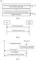
- FIG. 1 is a schematic flowchart of a method according to an embodiment of this application. As shown in FIG. 1 , the method 100 is performed by a terminal device. As shown in FIG. 1 , the method 100 includes the following steps.
- Step 110 The terminal device determines at least one target manner of an air interface technology.
- Step 120 The terminal device communicates with a network device by using the at least one target manner of the air interface technology.
- each air interface technology may have more than one optional manner, and one target manner of the air interface technology needs to be selected for network communication during actual communication. Therefore, the terminal device needs to determine the target manner of the air interface technology.
- the at least one target manner of the air interface technology includes at least one of the following manners: when the air interface technology is a random access manner, the target manner is one of the following: a random access manner of a long term evolution (Long Term Evolution, LTE) system or a simple random access manner; when the air interface technology is an uplink waveform, the target manner is one of the following: a cyclic prefix orthogonal frequency division multiplexing (cyclic prefix orthogonal frequency division multiplexing, CP-OFDM) manner or a discrete Fourier transform spread orthogonal frequency division multiplexing (discrete Fourier transform spread orthogonal frequency division multiplexing, DFT-S-OFDM) manner; when the air interface technology is an uplink multiple access manner, the target manner is one of the following: a sparse code multiple access (sparse code multiple access, SCMA) manner, a multi-user shared access (multi-user shared access, MUSA) manner, a low code rate spreading (low
- the terminal device determines the at least one target manner of the air interface technology according to a communications protocol.
- the terminal device may alternatively determine the at least one target manner of the air interface technology in another manner.
- that the terminal device determines at least one target manner of an air interface technology includes: receiving, by the terminal device, a notification message sent by the network device, where the notification message carries the at least one target manner of the air interface technology, and the at least one target manner of the air interface technology is determined by the network device from at least one optional manner of the air interface technology.
- the optional manner when the air interface technology is a random access manner, includes: a random access manner of a long term evolution (Long Term Evolution, LTE) system or a simple random access manner; when the air interface technology is an uplink waveform, the optional manner includes: a cyclic prefix orthogonal frequency division multiplexing (cyclic prefix orthogonal frequency division multiplexing, CP-OFDM) manner or a discrete Fourier transform spread orthogonal frequency division multiplexing (discrete Fourier transform spread orthogonal frequency division multiplexing, DFT-S-OFDM) manner; when the air interface technology is an uplink multiple access manner, the optional manner includes: a sparse code multiple access (sparse code multiple access, SCMA) manner, a multi-user shared access (multi-user shared access, MUSA) manner, a low code rate spreading (low code rate spreading) manner, a frequency domain spreading (frequency domain spreading) manner, a non-orthogonal coded multiple access (non
- SCMA sparse code multiple
- each of the listed manners of the air interface technology is an optional manner of the air interface technology.
- the optional manner includes: the random access manner of LTE or the simple random access manner.
- the target manner of the air interface technology is the random access manner of the LTE, or the target manner of the air interface technology is the simple random access manner.
- the terminal device can determine, from a plurality of optional manners of the air interface technology based on the notification message sent by the network device, the target manner that is of the air interface technology and that is used during actual communication, and can flexibly use a more appropriate manner of the air interface technology based on an actual communication situation, to adapt to different communication scenarios.
- the notification message is a system information sent by the network device
- the communicating with a network device by using the at least one target manner of the air interface technology includes: initially accessing the network device by using the at least one target manner of the air interface technology.
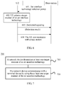
- FIG. 2 is a flowchart of a method according to an embodiment of this application. As shown in FIG. 2 , the method includes the following steps.
- Step 210 A base station sends a system information (system information) to UE, where the system information may be sent to the UE with a broadcasting manner, and the system information carries a target manner that is of an air interface technology and that is selected by a network device.
- system information system information
- Step 220 The UE performs initial random access based on the target manner that is of the air interface technology and that is selected by the network device.
- a selected target manner that is of an uplink waveform and that is in the system information broadcast by the base station is discrete Fourier transform spread orthogonal frequency division multiplexing (discrete Fourier transform spread orthogonal frequency division multiplexing, DFT-S-OFDM)
- DFT-S-OFDM discrete Fourier transform spread orthogonal frequency division multiplexing
- the base station determines at least one target manner of the air interface technology from at least one optional manner of the air interface technology based on an actual communication scenario. For example, before the UE initially and randomly accesses the base station, the base station has no information about the UE, does not know a location of the UE currently located in a cell, and does not know how an environment in which the UE is located is. Therefore, the base station selects a waveform manner with strongest robustness for the UE, that is, the DFT-S-OFDM manner.
- a terminal device can determine, from the plurality of optional manners of the air interface technology based on the notification message sent by the network device, a target manner that is of the air interface technology and that is used during initial access to a system, and can flexibly use a more appropriate manner of the air interface technology based on an actual communication situation, to adapt to different communication scenarios.
- the notification message is an initial random access message 2
- the communicating with the network device by using the at least one target manner of the air interface technology includes: sending message 3 of the initial random access to the network device by using the at least one target manner of the air interface technology.
- the at least one target manner that is of the air interface technology and that is applied to the message 3 of the initial random access can be determined, but also a target manner that is of the air interface technology and that is subsequently used during signaling interaction or data exchange with the network device can be specified. This is not limited in this application.
- FIG. 3 is a schematic flowchart of a method according to an embodiment of this application. It should be understood that the procedure may also be considered as a further elaboration of step 220 in FIG. 2 .
- the method includes the following steps. Step 221.
- the UE sends a preamble sequence (preamble) to the base station. It should be understood that the UE may use the method of the embodiment shown in FIG. 2 to determine a target manner of the air interface technology for initial random access, to send the preamble sequence.
- the preamble sequence is an initial random access message 1.
- the base station determines a target manner of the air interface technology.
- the network device may reselect, based on a change status of a network environment, a transmission service, and the like, the target manner that is of the air interface technology and that is used by the UE to communicate with the base station.
- the base station further determines at least one target manner of the air interface technology from at least one optional manner of the air interface technology based on a current communication scenario.
- Step 223. The base station sends message 2 of the initial random access to the UE, where the message 2 of the initial random access carries at least one target manner of the air interface technology.
- the base station notifies the UE of the at least one target manner of the air interface technology by using the message 2, so that the UE subsequently transmits data or signaling based on the at least one target manner that is of the air interface technology and that is carried in the message 2.
- Step 224 The UE sends message 3 to the base station.
- the UE sends the message 3 to the base station by using the at least one target manner that is of the air interface technology and that is selected by the base station.
- an initial random access manner of the UE is an existing LTE four-step random access manner, based on a preamble identity preamble ID in the message 2, all UEs that use the preamble in the message 1 receive the message 2. In other words, these UEs all receive the target manner that is of the air interface technology and that is reselected by the base station. In this case, these UEs all perform subsequent transmission based on the option reselected by the base station.
- the message 1 carries an identifier of the UE. In this case, the message 2 is sent only to the UE corresponding to the identifier carried in the message 1. To be specific, only the UE receives the target manner that is of the air interface technology and that is reselected by the base station, and performs subsequent transmission based on the option reselected by the base station.
- the at least one target manner that is of the air interface technology and that is carried in the message 2 of the initial random access includes a manner of an uplink waveform
- the sending message 3 of the initial random access to the network device by using the at least one target manner of the air interface technology includes: determining an RB allocation field content value in the message 2 of the initial random access; determining a resource location of the message 3 of the initial random access depending on whether the manner of the uplink waveform is discrete Fourier transform spread orthogonal frequency division multiplexing DFT-S-OFDM or cyclic prefix orthogonal frequency division multiplexing CP-OFDM, where a resource location of the message 3 of the initial random access that is determined when the manner of the uplink waveform is the DFT-S-OFDM is different from a resource location of the message 3 of the initial random access that is determined when the manner of the uplink waveform is the CP-OFDM; and sending the message 3 of the initial random access to the network device at the determined
- the UE determines the resource location of the message 3 of the initial random access depending on whether the manner of the uplink waveform is the DFT-S-OFDM or the CP-OFDM and based on the RB allocation field content value in an uplink grant (uplink grant, UL grant) in the message 2 when the RB allocation field content value is a specified value.
- a resource location of the message 3 varies according to a manner of the uplink waveform. This is because the DFT-S-OFDM always indicates consecutive resources in frequency domain, and the CP-OFDM may indicate non-consecutive resources in frequency domain.
- Step 225 The base station sends a contention resolution (contention resolution) message to the UE, namely, an initial random access message 4.
- a contention resolution (contention resolution) message to the UE, namely, an initial random access message 4.
- the UE performs subsequent data transmission and/or signaling transmission with the base station based on the target manner that is of the air interface technology and that is reselected by the base station.
- the optional manner includes the CP-OFDM and the DFT-S-OFDM.
- the base station can determine, based on the message 1, a cell in which the UE is currently located. If the UE is in a small cell, the base station determines a waveform manner of the CP-OFDM for the UE to use. If the UE is in a large cell, the base station can roughly determine, based on signal quality of the message 1, whether the UE is in a central region or an edge region of the large cell. If the UE is in the central region, the base station determines a waveform manner of the CP-OFDM for the UE to use. If the UE is in the edge region, of the base station determines a waveform manner of the DFT-S-OFDM for the UE to use.
- the terminal device can determine, from the plurality of optional manners of the air interface technology based on the notification message sent by the network device, a target manner that is of the air interface technology and that is used during initial random access to a system, and can flexibly use a more appropriate manner of the air interface technology based on an actual communication situation, to adapt to different communication scenarios.
- the network device is a target network device to which the terminal device expects to be handed over, and the notification message is an HO command.
- a source network device accessed by the UE determines that the UE is to be handed over to the target network device and sends a handover request (handover request) message to the target network device, and the target network device allows the request
- the target network device sends the HO command message to the UE.
- the message carries the at least one target manner that is of the air interface technology and that is selected by the target network device.
- the source base station when the source base station determines, based on a measurement report of the UE, that the UE is to be handed over to the target base station, the source base station sends the handover request (handover request) message to the target network device. If the target network device allows the request, before the UE is handed over to the target base station, the target base station selects the at least one target manner of the air interface technology from the at least one optional manner of the air interface technology based on information such as UE capability information and a measurement result of the UE in the received handover request message, and notifies the UE by using the HO command message.
- the target network device allows the request, before the UE is handed over to the target base station, the target base station selects the at least one target manner of the air interface technology from the at least one optional manner of the air interface technology based on information such as UE capability information and a measurement result of the UE in the received handover request message, and notifies the UE by using the HO command message.
- the target base station determines, for the UE, to use the waveform manner of the CP OFDM in the target cell. If the target base station determines to hand over the UE to a large cell served by the target base station, the target base station determines, for the UE, to use the waveform manner of the DFT-S-OFDM with strongest robustness in the target cell.
- FIG. 4 is a flowchart of a method according to an embodiment of this application. Referring to FIG. 4, FIG. 4 shows in detail an interaction process between UE and each of a source base station and a target base station in a handover process, including the following steps.
- the target base station determines a target manner that is of an air interface technology and that is to be used by the UE.
- Step 402. The target base station sends a handover request acknowledgement (handover request acknowledgement) message to the source base station, where the handover request acknowledgement message carries an HO command, and the HO command can be used to indicate the target manner that is of the air interface technology and that is selected by the target base station.
- handover request acknowledgement handover request acknowledgement
- Step 403. The source base station sends an RRC connection reconfiguration (RRC connection reconfiguration) message to the UE, where the connection reconfiguration message also carries the foregoing HO command.
- RRC connection reconfiguration RRC connection reconfiguration
- Step 404 The UE communicates with the target base station, and uses the target manner that is of the air interface technology and that is selected by the target base station.
- a terminal device can determine, from a plurality of optional manners of the air interface technology based on a notification message sent by a network device, a target manner that is of the air interface technology and that is used during handover to the network device, and can flexibly use a more appropriate manner of the air interface technology based on an actual communication situation, to adapt to different communication scenarios.
- the notification message is one of the following messages: a physical layer message, a MAC message, or an RRC message.
- the base station may re-determine, based on a capability of the UE and/or an environment in which the UE is located, a manner that is of the air interface technology and that is to be used by the UE.
- FIG. 5 is a schematic flowchart of a method according to an embodiment of this application.
- FIG. 5 shows that after UE initially and randomly accesses a network device, the network device reselects a target manner of an air interface technology and delivers the target manner of the air interface technology to the UE, and the UE communicates with the network device based on the target manner of the air interface technology.
- the method includes the following steps.
- Step 501 A base station determines a target manner that is of an air interface technology and that is to be used by UE.
- Step 502. The base station sends one of the following messages to the UE: a PHY message, a MAC message, or an RRC message. Regardless of a type of message specifically sent by the base station to the UE, the message carries at least one target manner that is of the air interface technology and that is selected by the base station for the UE.
- Step 503. The UE communicates with the network device.
- a terminal device can determine, from a plurality of optional manners of the air interface technology based on a notification message sent by the network device, a target manner that is of the air interface technology and that is used during communication with the network device, and can flexibly use a more appropriate manner of the air interface technology based on an actual communication situation, to adapt to different communication scenarios.
- the determining, by a terminal device, at least one target manner of an air interface technology includes: selecting, by the terminal device, the at least one target manner of the air interface technology from the at least one optional manner of the air interface technology according to an air interface technology selection policy.
- the terminal device may perform selection from the at least one optional manner of the air interface technology according to the air interface technology selection policy, and communicate with the network device by using the selected at least one target manner of the air interface technology.
- the UE may select a target manner of the air interface technology from the at least one optional manner of the air interface technology according to the air interface technology selection policy and based on information such as a current network environment, a capability of the UE, and a service that needs to be transmitted.
- the UE determines a to-be-used coding manner based on a condition that needs to be met by a length of the uplink control information that needs to be reported.
- a specific procedure is as follows: The base station broadcasts, in a system information, a length threshold of uplink control information using a polar code, or specifies, in a protocol, a length threshold of uplink control information using a polar code.
- the UE uses the polar code to perform channel coding on the uplink control information, and then performs transmission. Otherwise, the UE uses another manner.
- the UE When the UE needs to report the eMBB service uplink control information, the UE selects an appropriate channel coding manner based on the length of the uplink control information that needs to be reported. The UE performs channel coding on the uplink control information by using the coding manner, and then performs transmission. It should be understood that the base station reversely deduces the channel coding manner by using received data information.
- a to-be-used transmission manner is determined based on an environment in which the UE is currently located and based on a condition that needs to be met by a data volume of the uplink data that needs to be transmitted.
- the base station broadcasts, in a system information, a condition for using a grant-free transmission manner, or specifies, in a protocol, a condition for using a grant-free transmission manner, for example, based on a path loss threshold of a cell downlink signal, depending on whether the UE still remains in a cell in which the UE in the inactive mode (a third mode) is located, or based on a threshold of an uplink data volume that needs to be transmitted by the UE.
- the grant-free transmission manner is used. Otherwise, a 2-step RACH manner is adopted.
- an appropriate uplink data transmission manner is selected based on an environment in which the UE is currently located and a data volume of the uplink data that needs to be transmitted. The UE transmits the uplink data by using the determined transmission manner.
- the foregoing method further includes: receiving, by the terminal device, a system information sent by the network device, where the system information carries the air interface technology selection policy.
- the air interface technology selection policy may further carry a plurality of air interface technologies and optional manners of each air interface technology, so that the UE selects the target manner of the air interface technology according to the air interface technology policy.
- the UE may select the target manner of the air interface technology according to a communications protocol or an air interface technology policy delivered by the base station.
- the communicating with the network device by using the at least one target manner of the air interface technology includes: sending a selection notification message to the network device, where the selection notification message is used to indicate that the terminal device is to communicate with the network device by using the at least one target manner.
- the UE after selecting the target manner of the air interface technology, the UE needs to notify the network device of the selected manner of the air interface technology.
- FIG. 6 is a schematic flowchart of a method according to an embodiment of this application. As shown in FIG. 6 , the method includes the following steps.
- Step 601. Send an air interface technology selection policy to UE.
- Step 602. The UE selects a target manner of an air interface technology from optional manners of the air interface technology according to the air interface technology selection policy and based on information such as a current network environment, a capability of the UE, and a service that needs to be transmitted.
- Step 603. The UE sends a notification message to a base station by using dedicated information, where the notification message carries the target manner that is of the air interface technology and that is selected by the UE.
- Step 604. The UE communicates with the base station by using the selected target manner of the air interface technology.
- a terminal device can determine, from the plurality of optional manners of the air interface technology based on the notification message sent by a network device, the target manner that is of the air interface technology and that is used during communication with the network device, and can flexibly use a more appropriate manner of the air interface technology based on an actual communication situation, to adapt to different communication scenarios.
- FIG. 7 is a schematic flowchart of a method according to another embodiment of this application.
- the method may be performed by a network device.
- the network device may be a base station.
- the method 700 includes the following steps.
- Step 710 The network device determines at least one target manner of an air interface technology.
- Step 720 The network device communicates with a terminal device by using the at least one target manner of the air interface technology.
- the at least one target manner of the air interface technology is the same as the target manner of the air interface technology in the embodiment shown in FIG. 1 . Details are not described herein again.
- a target manner that is of an air interface technology and that is used during actual communication can be determined from a plurality of optional manners of the air interface technology.
- the determining, by the network device, at least one target manner of an air interface technology includes: determining, by the network device, the at least one target manner of the air interface technology from at least one optional manner of the air interface technology; and sending, by the network device, a notification message to the terminal device, where the notification message carries the at least one target manner of the air interface technology.
- the notification message is a system information, so that the terminal device initially and randomly accesses the network device by using the at least one target manner of the air interface technology.
- the notification message is an initial random access message 2, so that the terminal device sends message 3 of the initial random access to the network device by using the at least one target manner of the air interface technology.
- the network device is a target network device to which the terminal device expects to be handed over, and the notification message is an HO command message.
- the notification message is one of the following messages: a physical layer message, a media access control MAC message, or a radio resource control RRC message.
- the terminal device can determine, from the plurality of optional manners of the air interface technology based on the notification message sent by the network device, the target manner that is of the air interface technology and that is used during communication with the network device, and can flexibly use a more appropriate manner of the air interface technology based on an actual communication situation, to adapt to different communication scenarios.
- Procedures of the methods of the embodiments of this application are described in detail with reference to FIG. 1 to FIG. 7 .
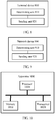
- FIG. 8 is a schematic block diagram of a terminal device 800 according to an embodiment of this application.
- the terminal device 800 can perform the steps that are performed by the terminal device in the methods in FIG. 1 to FIG. 7 . To avoid repetition, details are not described herein again.
- the terminal device 800 includes:
- FIG. 9 is a schematic block diagram of a network device 900 according to an embodiment of this application.
- the network device 900 can perform the steps that are performed by the network device in the methods in FIG. 1 to FIG. 7 . To avoid repetition, details are not described herein again.
- the network device 900 includes:
- the network device provided in this embodiment of this application can determine, from a plurality of optional manners of the air interface technology, the target manner that is of the air interface technology and that is used during actual communication.
- FIG. 10 is a schematic structural block diagram of an apparatus 1000 according to another embodiment of this application. It should be understood that the apparatus 1000 can perform the steps that are performed by the terminal device in the methods in FIG. 1 to FIG. 7 . To avoid repetition, details are not described herein again.
- the apparatus 1000 includes:
- the apparatus provided in this embodiment of this application can determine, from a plurality of optional manners of the air interface technology, the target manner that is of the air interface technology and that is used during actual communication.
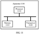
- FIG. 11 is a schematic structural block diagram of an apparatus 1100 according to another embodiment of this application. It should be understood that the apparatus 1100 can perform the steps that are performed by a network device in the methods in FIG. 1 to FIG. 7 . To avoid repetition, details are not described herein again.
- the apparatus 1100 includes:
- the apparatus provided in this embodiment of this application can determine, from a plurality of optional manners of the air interface technology, the target manner that is of the air interface technology and that is used during actual communication.
- the disclosed system, apparatus, and method may be implemented in other manners.
- the described apparatus embodiment is merely an example.
- the unit division is merely logical function division and may be other division in actual implementation.
- a plurality of units or components may be combined or integrated into another system, or some features may be ignored or not performed.
- the displayed or discussed mutual couplings or direct couplings or communication connections may be implemented by using some interfaces.
- the indirect couplings or communication connections between the apparatuses or units may be implemented in electronic, mechanical, or other forms.
- the units described as separate parts may or may not be physically separate, and parts displayed as units may or may not be physical units, may be located in one position, or may be distributed on a plurality of network units. Some or all of the units may be selected according to actual needs to achieve the objectives of the solutions of the embodiments.
- the functions When the functions are implemented in a form of a software functional unit and sold or used as an independent product, the functions may be stored in a computer-readable storage medium. Based on such an understanding, the technical solutions of this application essentially, or the part contributing to the prior art, or some of the technical solutions may be implemented in a form of a software product.
- the computer software product is stored in a storage medium, and includes several instructions for instructing a computer device (which may be a personal computer, a server, or a network device) to perform all or some of the steps of the methods described in the embodiments of the present invention.
- the foregoing storage medium includes any medium that can store program code, such as a USB flash drive, a removable hard disk, a read-only memory (Read-Only Memory, ROM), a random access memory (Random Access Memory, RAM), a magnetic disk, or an optical disc.
- program code such as a USB flash drive, a removable hard disk, a read-only memory (Read-Only Memory, ROM), a random access memory (Random Access Memory, RAM), a magnetic disk, or an optical disc.
Landscapes
- Engineering & Computer Science (AREA)
- Signal Processing (AREA)
- Computer Networks & Wireless Communication (AREA)
- Computer Security & Cryptography (AREA)
- Physics & Mathematics (AREA)
- Mathematical Physics (AREA)
- Mobile Radio Communication Systems (AREA)
Description
- Embodiments of this application relate to the communications field, and more specifically, to a communication method of a terminal, a method of a network device, a terminal device, and a network device for selecting uplink air interface waveform technology.
- In long term evolution (Long Term Evolution, LTE) technologies, various air interface technologies (air interface technologies such as a random access manner, an uplink waveform, an uplink multiple access manner, a modulation scheme, and a duplexing manner) all use one or more determined manners. It is defined in a communications protocol that for an air interface technology, a particular manner is always used or a particular manner is used under a specified condition.
- In an existing LTE system, because most air interface technologies use only a fixed manner, for example, a transmission time interval (transmission time interval, TTI length) has only one manner of 1 ms, when a terminal device initially accesses a network device, the terminal device accesses the system in a manner defined in the protocol. However, in a 5G system, each air interface technology may use a plurality of optional manners, and the possible manners may respectively have use conditions.
- Therefore, a technical means is urgently needed to select, from a plurality of optional manners of the air interface technology based on an actual situation, a manner that is of the air interface technology and that is used during actual communication between a terminal device and a network device.
- Document R1-1611375 mainly relates to applicable RACH procedure for several NR deployment scenarios, in which provides that: (1) Cell discovery signals including PSS/SSS and NR-PBCH may be cell-specifically configured and transmitted in an SFN manner across a set of TRPs, (2) For RRC connection establishment consider different mechanisms through which a UE acquires the RACH configuration and (3) The UL waveform for RACH procedure should either be pre-determined or signaled in system information.
- Document R1-1609425 mainly relates to a discussion of UE behavior on mixed numerology carrier.
- Document R1-1611651 mainly relates to a discussion on numerology determination during initial access, in which provides that: Proposal 1: The numerologies of control channel for SIBx and SIBx itself during initial access are predefined the same as that for SS/PBCH; Proposal 2: The numerology for preamble during initial access is predefined for a given frequency range or indicated by SIBx; Proposal 3: The numerology for Ctrl-RAR/RAR during initial access is predefined the same as that for SS/PBCH or indicated by SIBx; and Proposal 4: The numerology for Msg. 3 / Msg. 4 during initial access is flexible considering service or deployment scenario diversity.
- Document
WO2018/085701 A1 mainly relates to a method that NR provides variable transmission schemes with respect to waveform, numerology, transmission bandwidth, and transmission duration. Mechanisms are described that provide transmission scheme alignments for the RACH procedure, particular for what is referred to asmessage 3 transmitted by the terminal. - Document
WO2018/087124 A1 mainly relates to a method in a network node for managing random-access procedures with a plurality of wireless devices, in which an indication of a modulation format is transmitted to one or more of the plurality of wireless devices to configure the modulation format for a random access message (3) transmission from the one or more wireless devices. - The invention is defined in the claims. In the following, parts of the description and drawings referring to embodiments which are not covered by the claims are not presented as embodiments of the invention, but as examples useful for understanding the invention.
- According to a first aspect, a communication method is provided, including: receiving, by a terminal device, a system information sent by a network device, wherein the system information carries a first target manner of an uplink waveform of an air interface technology, and the first target manner of an uplink waveform is determined by the network device from at least one optional manner of the air interface technology; sending, by the terminal device,
message 3 by using the first target manner of the uplink waveform to the network device to perform an initial random access; receiving, by the terminal device, a message sent by the network device, wherein the message is a radio resource control, RRC, message, and wherein the message carries a second target manner of an uplink waveform, and the second target manner of an uplink waveform is determined by the network device from at least one optional manner of the air interface technology; and communicating, by the terminal device, by using the second target manner of the uplink waveform with the network device. - According to a second aspect, a communication method is provided, including: sending, by a network device, a system information to a terminal device, wherein the system information carries a first target manner of an uplink waveform of an air interface technology, and the first target manner of an uplink waveform is determined by the network device from at least one optional manner of the air interface technology; receiving, by the network device,
message 3 in the first target manner of the uplink waveform sent by the terminal device to perform an initial random access; sending, by the network device, a message to the terminal device, wherein the message is a radio resource control, RRC, message, and wherein the message carries a second target manner of an uplink waveform, and the second target manner of an uplink waveform is determined by the network device from at least one optional manner of the air interface technology; and communicating, by the network device, by using the second target manner of the uplink waveform with the terminal device. - According to a third aspect, a terminal device is provided. The terminal device is configured to implement the method in the first aspect or any possible implementation of the first aspect. Specifically, the terminal device includes a unit for performing the method in the first aspect or any possible implementation of the first aspect.
- According to a fourth aspect, a network device is provided. The network device is configured to implement the method in the second aspect or any possible implementation of the second aspect. Specifically, the network device includes a unit for performing the method in the second aspect or any possible implementation of the second aspect.
- According to a seventh aspect, a computer readable medium is provided. The computer readable medium is configured to store a computer program. The computer program includes an instruction for performing the method in the first aspect or any possible implementation of the first aspect.
- According to an eighth aspect, a computer readable medium is provided. The computer readable medium is configured to store a computer program. The computer program includes an instruction for performing the method in the second aspect or any possible implementation of the second aspect.
-
-
FIG. 1 is a schematic flowchart of a method according to an embodiment of this application; -
FIG. 2 is a flowchart of a method according to an embodiment of this application; -
FIG. 3 is a schematic flowchart of a method according to an embodiment of this application; -
FIG. 4 is a flowchart of a method according to an embodiment of this application; -
FIG. 5 is a schematic flowchart of a method according to an embodiment of this application; -
FIG. 6 is a schematic flowchart of a method according to an embodiment of this application; -
FIG. 7 is a schematic flowchart of a method according to another embodiment of this application; -
FIG. 8 is a schematic block diagram of aterminal device 800 according to an embodiment of this application; -
FIG. 9 is a schematic block diagram of anetwork device 900 according to an embodiment of this application; -
FIG. 10 is a schematic structural block diagram of an apparatus 1000 according to another embodiment of this application; and -
FIG. 11 is a schematic structural block diagram of an apparatus 1100 according to another embodiment of this application. - The following describes the technical solutions in the embodiments of this application with reference to the accompanying drawings.
- In the embodiments of this application, a terminal device may be user equipment (user equipment, UE), an access terminal, a subscriber unit, a subscriber station, a mobile station, a mobile console, a remote station, a remote terminal, a mobile device, a user terminal, a wireless communications device, a user agent, or a user apparatus. The access terminal may be a cellular phone, a cordless phone, a Session Initiation Protocol (Session Initiation Protocol, SIP) phone, a wireless local loop (wireless local loop, WLL) station, a personal digital assistant (personal digital assistant, PDA), a handheld device having a wireless communication function, a computing device, another processing device connected to a wireless modem, an in-vehicle device, a wearable device, or a terminal device in a future 5G network.
- Further, in the embodiments of this application, a base station may be a network device for communication with the terminal device. For example, the base station may be a base transceiver station (base transceiver station, BTS) in a GSM system or CDMA, or may be a NodeB (NodeB, NB) in a WCDMA system, or may be an evolved NodeB (Evolutional Node B, eNB or eNodeB) in an LTE system. Alternatively, the base station may be a relay station, an access point, an in-vehicle device, a wearable device, a network-side device in a future 5G network, or the like.
FIG. 1 is a schematic flowchart of a method according to an embodiment of this application. As shown inFIG. 1 , themethod 100 is performed by a terminal device. As shown inFIG. 1 , themethod 100 includes the following steps. -
Step 110. The terminal device determines at least one target manner of an air interface technology. -
Step 120. The terminal device communicates with a network device by using the at least one target manner of the air interface technology. - It should be understood that each air interface technology may have more than one optional manner, and one target manner of the air interface technology needs to be selected for network communication during actual communication. Therefore, the terminal device needs to determine the target manner of the air interface technology.
- Optionally, in an embodiment of this application, the at least one target manner of the air interface technology includes at least one of the following manners: when the air interface technology is a random access manner, the target manner is one of the following: a random access manner of a long term evolution (Long Term Evolution, LTE) system or a simple random access manner; when the air interface technology is an uplink waveform, the target manner is one of the following: a cyclic prefix orthogonal frequency division multiplexing (cyclic prefix orthogonal frequency division multiplexing, CP-OFDM) manner or a discrete Fourier transform spread orthogonal frequency division multiplexing (discrete Fourier transform spread orthogonal frequency division multiplexing, DFT-S-OFDM) manner; when the air interface technology is an uplink multiple access manner, the target manner is one of the following: a sparse code multiple access (sparse code multiple access, SCMA) manner, a multi-user shared access (multi-user shared access, MUSA) manner, a low code rate spreading (low code rate spreading) manner, a frequency domain spreading (frequency domain spreading) manner, a non-orthogonal coded multiple access (non-orthogonal coded multiple access, NCMA) manner, a non-orthogonal multiple access (non-orthogonal multiple access, NOMA) manner, a pattern division multiple access (pattern division multiple access, PDMA) manner, a resource spread multiple access (resource spread multiple access, RSMA) manner, an interleave-grid multiple access (interleave-grid multiple access, IGMA) manner, a low density spreading with signature vector extension (low density spreading with signature vector extension, LDS-SVE) manner, a low code rate and signature based shared access (low code rate and signature based shared access, LSSA) manner, a non-orthogonal coded access (non-orthogonal coded access, NOCA) manner, an interleave division multiple access (interleave division multiple access, IDMA) manner, a repetition division multiple access (repetition division multiple access, RDMA) manner, or a group orthogonal coded access (group orthogonal coded access, GOCA) manner; when the air interface technology is a modulation scheme, the target manner is one of the following: a quadrature phase shift keying (quadrature phase shift keying, QPSK) scheme, a 16 quadrature amplitude modulation 16 (quadrature amplitude modulation, QAM) scheme, a 64 quadrature amplitude modulation 64QAM scheme, a 256 quadrature amplitude modulation 256QAM scheme, a constellation mapping among subcarriers (constellation mapping among subcarriers) scheme, a non-uniform quadrature amplitude modulation (non-uniform QAM) scheme, a higher order modulation in conjunction with MIMO (higher order modulation in conjunction with MIMO), a coded modulation (coded modulations) scheme, a spatial modulation (spatial modulation) scheme, a scheme of mappings of bits to symbols rotated-quadrature amplitude modulation up to quadrature phase shift keying (mappings of bits to symbol(s) rotated-QAM up to QPSK), or constellation interpolation (Constellation Interpolation); when the air interface technology is a duplexing manner, the target manner is one of the following: a frequency division duplex (frequency division duplexing, FDD) manner, a time division duplex (time division duplex, TDD) manner, a dynamic time division duplex (dynamic TDD) manner, a flexible duplex (flexible duplex) manner, a space division full-duplex (space division full-duplex) manner, or an in-band full-duplex (In-band full-duplex) manner; when the air interface technology is an enhanced mobile broadband (enhanced mobile broadband, eMBB) service uplink control channel coding manner, the target manner is one of the following: a polar code (polar codes) coding manner, a repetition (repetition) coding manner, or a block coding (block coding) manner; when the air interface technology is an inactive uplink data transmission manner, the target manner is one of the following: a grant-free transmission manner or a 2-step random access 2-step RACH manner; when the air interface technology is a subcarrier spacing, the target manner is one of the following: 15
kHz ∗ 2n, where n is an integer; when the air interface technology is a slot type, the target manner is one of the following cases in which slot duration (slot duration) is 7 orthogonal frequency division multiplex OFDM symbols or 14 orthogonal frequency division multiplex OFDM symbols, or mini-slot duration (mini-slot duration) is m OFDM symbols, where m ∈ {1,6}; and/or when the air interface technology is a transmission TTI length, the target manner is one of the following: {a downlink short TTI length: 2 OFDM symbols, an uplink short TTI length: 2 OFDM symbols}, {a downlink short TTI length: 2 OFDM symbols, an uplink short TTI length: 4 OFDM symbols}, {a downlink short TTI length: 2 OFDM symbols, an uplink short TTI length: 7 OFDM symbols}, {a downlink short TTI length: 7 OFDM symbols, an uplink short TTI length: 7 OFDM symbols}, {a downlink short TTI length: 2 OFDM symbols, an uplink short TTI length: 14 OFDM symbols}, or {a downlink short TTI length: 7 OFDM symbols, an uplink short TTI length: 14 OFDM symbols}. - Optionally, in an embodiment of this application, the terminal device determines the at least one target manner of the air interface technology according to a communications protocol. Optionally, the terminal device may alternatively determine the at least one target manner of the air interface technology in another manner.
- Optionally, in an embodiment of this application, that the terminal device determines at least one target manner of an air interface technology includes: receiving, by the terminal device, a notification message sent by the network device, where the notification message carries the at least one target manner of the air interface technology, and the at least one target manner of the air interface technology is determined by the network device from at least one optional manner of the air interface technology.
- Optionally, in an embodiment of this application, when the air interface technology is a random access manner, the optional manner includes: a random access manner of a long term evolution (Long Term Evolution, LTE) system or a simple random access manner; when the air interface technology is an uplink waveform, the optional manner includes: a cyclic prefix orthogonal frequency division multiplexing (cyclic prefix orthogonal frequency division multiplexing, CP-OFDM) manner or a discrete Fourier transform spread orthogonal frequency division multiplexing (discrete Fourier transform spread orthogonal frequency division multiplexing, DFT-S-OFDM) manner; when the air interface technology is an uplink multiple access manner, the optional manner includes: a sparse code multiple access (sparse code multiple access, SCMA) manner, a multi-user shared access (multi-user shared access, MUSA) manner, a low code rate spreading (low code rate spreading) manner, a frequency domain spreading (frequency domain spreading) manner, a non-orthogonal coded multiple access (non-orthogonal coded multiple access, NCMA) manner, a non-orthogonal multiple access (non-orthogonal multiple access, NOMA) manner, a pattern division multiple access (pattern division multiple access, PDMA) manner, a resource spread multiple access (resource spread multiple access, RSMA) manner, an interleave-grid multiple access (interleave-grid multiple access, IGMA) manner, a low density spreading with signature vector extension (low density spreading with signature vector extension, LDS-SVE) manner, a low code rate and signature based shared access (low code rate and signature based shared access, LSSA) manner, a non-orthogonal coded access (non-orthogonal coded access, NOCA) manner, an interleave division multiple access (interleave division multiple access, IDMA) manner, a repetition division multiple access (repetition division multiple access, RDMA) manner, or a group orthogonal coded access (group orthogonal coded access, GOCA) manner; when the air interface technology is a modulation scheme, the optional manner includes: a quadrature phase shift keying (quadrature phase shift keying, QPSK) scheme, a 16 quadrature amplitude modulation 16 (quadrature amplitude modulation, QAM) scheme, a 64 quadrature amplitude modulation 64QAM scheme, a 256 quadrature amplitude modulation 256QAM scheme, a constellation mapping among subcarriers (constellation mapping among subcarriers) scheme, a non-uniform quadrature amplitude modulation (non-uniform QAM) scheme, a higher order modulation in conjunction with MIMO (higher order modulation in conjunction with MIMO), a coded modulation (coded modulations) scheme, a spatial modulation (spatial modulation) scheme, a scheme of mappings of bits to symbols rotated-quadrature amplitude modulation up to quadrature phase shift keying (mappings of bits to symbol(s) rotated-QAM up to QPSK), or constellation interpolation (Constellation Interpolation); when the air interface technology is a duplexing manner, the optional manner includes: a frequency division duplex (frequency division duplexing, FDD) manner, a time division duplex (time division duplex, TDD) manner, a dynamic time division duplex (dynamic TDD) manner, a flexible duplex (flexible duplex) manner, a space division full-duplex (space division full-duplex) manner, or an in-band full-duplex (In-band full-duplex) manner; when the air interface technology is an enhanced mobile broadband (enhanced mobile broadband, eMBB) service uplink control channel coding manner, the target manner is one of the following: a polar code (polar codes) coding manner, a repetition (repetition) coding manner, or a block coding (block coding) manner; when the air interface technology is an inactive uplink data transmission manner, the optional manner includes: a grant-free transmission manner or a 2-step random access 2-step RACH manner; when the air interface technology is a subcarrier spacing, the target manner is one of the following: 15
kHz ∗ 2n, where n is an integer; when the air interface technology is a slot type, the target manner is one of the following cases in which: slot duration (slot duration) is 7 orthogonal frequency division multiplex OFDM symbols or 14 orthogonal frequency division multiplex OFDM symbols, or mini-slot duration (mini-slot duration) is m OFDM symbols, where m ∈ {1,6}; and/or when the air interface technology is a transmission TTI length, the target manner is one of the following: {a downlink short TTI length: 2 OFDM symbols, an uplink short TTI length: 2 OFDM symbols}, {a downlink short TTI length: 2 OFDM symbols, an uplink short TTI length: 4 OFDM symbols}, {a downlink short TTI length: 2 OFDM symbols, an uplink short TTI length: 7 OFDM symbols}, {a downlink short TTI length: 7 OFDM symbols, an uplink short TTI length: 7 OFDM symbols}, {a downlink short TTI length: 2 OFDM symbols, an uplink short TTI length: 14 OFDM symbols}, or {a downlink short TTI length: 7 OFDM symbols, an uplink short TTI length: 14 OFDM symbols}. - It should be understood that each of the listed manners of the air interface technology is an optional manner of the air interface technology. For example, when the air interface technology is the random access manner, the optional manner includes: the random access manner of LTE or the simple random access manner. The target manner of the air interface technology is the random access manner of the LTE, or the target manner of the air interface technology is the simple random access manner.
- Therefore, the terminal device can determine, from a plurality of optional manners of the air interface technology based on the notification message sent by the network device, the target manner that is of the air interface technology and that is used during actual communication, and can flexibly use a more appropriate manner of the air interface technology based on an actual communication situation, to adapt to different communication scenarios.
- Optionally, in an embodiment of this application, the notification message is a system information sent by the network device, and the communicating with a network device by using the at least one target manner of the air interface technology includes: initially accessing the network device by using the at least one target manner of the air interface technology.
-
FIG. 2 is a flowchart of a method according to an embodiment of this application. As shown inFIG. 2 , the method includes the following steps. -
Step 210. A base station sends a system information (system information) to UE, where the system information may be sent to the UE with a broadcasting manner, and the system information carries a target manner that is of an air interface technology and that is selected by a network device. -
Step 220. The UE performs initial random access based on the target manner that is of the air interface technology and that is selected by the network device. - Specifically, for example, when a selected target manner that is of an uplink waveform and that is in the system information broadcast by the base station is discrete Fourier transform spread orthogonal frequency division multiplexing (discrete Fourier transform spread orthogonal frequency division multiplexing, DFT-S-OFDM), the UE performs initial random access by using the DFT-S-OFDM manner, to access the network device.
- Specifically, the base station determines at least one target manner of the air interface technology from at least one optional manner of the air interface technology based on an actual communication scenario. For example, before the UE initially and randomly accesses the base station, the base station has no information about the UE, does not know a location of the UE currently located in a cell, and does not know how an environment in which the UE is located is. Therefore, the base station selects a waveform manner with strongest robustness for the UE, that is, the DFT-S-OFDM manner.
- Therefore, a terminal device can determine, from the plurality of optional manners of the air interface technology based on the notification message sent by the network device, a target manner that is of the air interface technology and that is used during initial access to a system, and can flexibly use a more appropriate manner of the air interface technology based on an actual communication situation, to adapt to different communication scenarios.
- Optionally, in an embodiment of this application, the notification message is an initial
random access message 2, and the communicating with the network device by using the at least one target manner of the air interface technology includes: sendingmessage 3 of the initial random access to the network device by using the at least one target manner of the air interface technology. - It should be understood that based on the initial
random access message 2, not only the at least one target manner that is of the air interface technology and that is applied to themessage 3 of the initial random access can be determined, but also a target manner that is of the air interface technology and that is subsequently used during signaling interaction or data exchange with the network device can be specified. This is not limited in this application. - Specifically,
FIG. 3 is a schematic flowchart of a method according to an embodiment of this application. It should be understood that the procedure may also be considered as a further elaboration ofstep 220 inFIG. 2 . As shown inFIG. 3 , the method includes the following steps.Step 221. The UE sends a preamble sequence (preamble) to the base station. It should be understood that the UE may use the method of the embodiment shown inFIG. 2 to determine a target manner of the air interface technology for initial random access, to send the preamble sequence. The preamble sequence is an initial random access message 1. -
Step 222. The base station determines a target manner of the air interface technology. To be specific, the network device may reselect, based on a change status of a network environment, a transmission service, and the like, the target manner that is of the air interface technology and that is used by the UE to communicate with the base station. In other words, the base station further determines at least one target manner of the air interface technology from at least one optional manner of the air interface technology based on a current communication scenario. -
Step 223. The base station sendsmessage 2 of the initial random access to the UE, where themessage 2 of the initial random access carries at least one target manner of the air interface technology. In other words, the base station notifies the UE of the at least one target manner of the air interface technology by using themessage 2, so that the UE subsequently transmits data or signaling based on the at least one target manner that is of the air interface technology and that is carried in themessage 2. -
Step 224. The UE sendsmessage 3 to the base station. To be specific, the UE sends themessage 3 to the base station by using the at least one target manner that is of the air interface technology and that is selected by the base station. - It should be understood that, if an initial random access manner of the UE is an existing LTE four-step random access manner, based on a preamble identity preamble ID in the
message 2, all UEs that use the preamble in the message 1 receive themessage 2. In other words, these UEs all receive the target manner that is of the air interface technology and that is reselected by the base station. In this case, these UEs all perform subsequent transmission based on the option reselected by the base station. If an initial random access of the UE is a simplified 2-step random access manner, the message 1 carries an identifier of the UE. In this case, themessage 2 is sent only to the UE corresponding to the identifier carried in the message 1. To be specific, only the UE receives the target manner that is of the air interface technology and that is reselected by the base station, and performs subsequent transmission based on the option reselected by the base station. - Optionally, in an embodiment of this application, the at least one target manner that is of the air interface technology and that is carried in the
message 2 of the initial random access includes a manner of an uplink waveform, and the sendingmessage 3 of the initial random access to the network device by using the at least one target manner of the air interface technology includes: determining an RB allocation field content value in themessage 2 of the initial random access; determining a resource location of themessage 3 of the initial random access depending on whether the manner of the uplink waveform is discrete Fourier transform spread orthogonal frequency division multiplexing DFT-S-OFDM or cyclic prefix orthogonal frequency division multiplexing CP-OFDM, where a resource location of themessage 3 of the initial random access that is determined when the manner of the uplink waveform is the DFT-S-OFDM is different from a resource location of themessage 3 of the initial random access that is determined when the manner of the uplink waveform is the CP-OFDM; and sending themessage 3 of the initial random access to the network device at the determined resource location. - To be specific, the UE determines the resource location of the
message 3 of the initial random access depending on whether the manner of the uplink waveform is the DFT-S-OFDM or the CP-OFDM and based on the RB allocation field content value in an uplink grant (uplink grant, UL grant) in themessage 2 when the RB allocation field content value is a specified value. Generally, a resource location of themessage 3 varies according to a manner of the uplink waveform. This is because the DFT-S-OFDM always indicates consecutive resources in frequency domain, and the CP-OFDM may indicate non-consecutive resources in frequency domain. -
Step 225. The base station sends a contention resolution (contention resolution) message to the UE, namely, an initial random access message 4. - Further, the UE performs subsequent data transmission and/or signaling transmission with the base station based on the target manner that is of the air interface technology and that is reselected by the base station.
- When the air interface technology is the uplink waveform, the optional manner includes the CP-OFDM and the DFT-S-OFDM. In this case, the base station can determine, based on the message 1, a cell in which the UE is currently located. If the UE is in a small cell, the base station determines a waveform manner of the CP-OFDM for the UE to use. If the UE is in a large cell, the base station can roughly determine, based on signal quality of the message 1, whether the UE is in a central region or an edge region of the large cell. If the UE is in the central region, the base station determines a waveform manner of the CP-OFDM for the UE to use. If the UE is in the edge region, of the base station determines a waveform manner of the DFT-S-OFDM for the UE to use.
- Therefore, the terminal device can determine, from the plurality of optional manners of the air interface technology based on the notification message sent by the network device, a target manner that is of the air interface technology and that is used during initial random access to a system, and can flexibly use a more appropriate manner of the air interface technology based on an actual communication situation, to adapt to different communication scenarios.
- Optionally, in an embodiment of this application, the network device is a target network device to which the terminal device expects to be handed over, and the notification message is an HO command.
- To be specific, when a source network device accessed by the UE determines that the UE is to be handed over to the target network device and sends a handover request (handover request) message to the target network device, and the target network device allows the request, the target network device sends the HO command message to the UE. The message carries the at least one target manner that is of the air interface technology and that is selected by the target network device.
- In other words, specifically, when the source base station determines, based on a measurement report of the UE, that the UE is to be handed over to the target base station, the source base station sends the handover request (handover request) message to the target network device. If the target network device allows the request, before the UE is handed over to the target base station, the target base station selects the at least one target manner of the air interface technology from the at least one optional manner of the air interface technology based on information such as UE capability information and a measurement result of the UE in the received handover request message, and notifies the UE by using the HO command message. For example, if the target base station determines, based on the UE capability information and the measurement result of the UE in the received handover request message, to hand over the UE to a small cell served by the target base station, the target base station determines, for the UE, to use the waveform manner of the CP OFDM in the target cell. If the target base station determines to hand over the UE to a large cell served by the target base station, the target base station determines, for the UE, to use the waveform manner of the DFT-S-OFDM with strongest robustness in the target cell.
-
FIG. 4 is a flowchart of a method according to an embodiment of this application. Referring toFIG. 4, FIG. 4 shows in detail an interaction process between UE and each of a source base station and a target base station in a handover process, including the following steps. - Step 401. The target base station determines a target manner that is of an air interface technology and that is to be used by the UE.
-
Step 402. The target base station sends a handover request acknowledgement (handover request acknowledgement) message to the source base station, where the handover request acknowledgement message carries an HO command, and the HO command can be used to indicate the target manner that is of the air interface technology and that is selected by the target base station. - Step 403. The source base station sends an RRC connection reconfiguration (RRC connection reconfiguration) message to the UE, where the connection reconfiguration message also carries the foregoing HO command.
-
Step 404. The UE communicates with the target base station, and uses the target manner that is of the air interface technology and that is selected by the target base station. - Therefore, a terminal device can determine, from a plurality of optional manners of the air interface technology based on a notification message sent by a network device, a target manner that is of the air interface technology and that is used during handover to the network device, and can flexibly use a more appropriate manner of the air interface technology based on an actual communication situation, to adapt to different communication scenarios.
- Optionally, in an embodiment of this application, after the terminal device initially and randomly accesses the network device, the notification message is one of the following messages: a physical layer message, a MAC message, or an RRC message.
- In other words, regardless of a manner used by the UE, after the UE initially and randomly accesses the network device, the base station may re-determine, based on a capability of the UE and/or an environment in which the UE is located, a manner that is of the air interface technology and that is to be used by the UE.
- Specifically,
FIG. 5 is a schematic flowchart of a method according to an embodiment of this application.FIG. 5 shows that after UE initially and randomly accesses a network device, the network device reselects a target manner of an air interface technology and delivers the target manner of the air interface technology to the UE, and the UE communicates with the network device based on the target manner of the air interface technology. As shown inFIG. 5 , the method includes the following steps. - Step 501. A base station determines a target manner that is of an air interface technology and that is to be used by UE.
-
Step 502. The base station sends one of the following messages to the UE: a PHY message, a MAC message, or an RRC message. Regardless of a type of message specifically sent by the base station to the UE, the message carries at least one target manner that is of the air interface technology and that is selected by the base station for the UE. -
Step 503. The UE communicates with the network device. - Therefore, a terminal device can determine, from a plurality of optional manners of the air interface technology based on a notification message sent by the network device, a target manner that is of the air interface technology and that is used during communication with the network device, and can flexibly use a more appropriate manner of the air interface technology based on an actual communication situation, to adapt to different communication scenarios.
- Optionally, in an embodiment of this application, the determining, by a terminal device, at least one target manner of an air interface technology includes: selecting, by the terminal device, the at least one target manner of the air interface technology from the at least one optional manner of the air interface technology according to an air interface technology selection policy.
- In other words, the terminal device may perform selection from the at least one optional manner of the air interface technology according to the air interface technology selection policy, and communicate with the network device by using the selected at least one target manner of the air interface technology.
- It should be understood that the UE may select a target manner of the air interface technology from the at least one optional manner of the air interface technology according to the air interface technology selection policy and based on information such as a current network environment, a capability of the UE, and a service that needs to be transmitted.
- Optionally, in an embodiment of this application, when the UE needs to report eMBB service uplink control information, the UE determines a to-be-used coding manner based on a condition that needs to be met by a length of the uplink control information that needs to be reported. A specific procedure is as follows: The base station broadcasts, in a system information, a length threshold of uplink control information using a polar code, or specifies, in a protocol, a length threshold of uplink control information using a polar code. When the length of the uplink control information that needs to be reported by the UE is greater than the threshold, the UE uses the polar code to perform channel coding on the uplink control information, and then performs transmission. Otherwise, the UE uses another manner. When the UE needs to report the eMBB service uplink control information, the UE selects an appropriate channel coding manner based on the length of the uplink control information that needs to be reported. The UE performs channel coding on the uplink control information by using the coding manner, and then performs transmission. It should be understood that the base station reversely deduces the channel coding manner by using received data information.
- Optionally, in an embodiment of this application, when the UE in an inactive mode needs to transmit uplink data, a to-be-used transmission manner is determined based on an environment in which the UE is currently located and based on a condition that needs to be met by a data volume of the uplink data that needs to be transmitted. The base station broadcasts, in a system information, a condition for using a grant-free transmission manner, or specifies, in a protocol, a condition for using a grant-free transmission manner, for example, based on a path loss threshold of a cell downlink signal, depending on whether the UE still remains in a cell in which the UE in the inactive mode (a third mode) is located, or based on a threshold of an uplink data volume that needs to be transmitted by the UE. If a path loss that is of the cell downlink signal and that is detected by the UE is less than a specified threshold, or the UE still remains in the cell in which the UE in the inactive mode is located, and the uplink data that needs to be transmitted by the UE is less than a specified threshold, the grant-free transmission manner is used. Otherwise, a 2-step RACH manner is adopted. When the UE in the inactive mode needs to transmit uplink data, an appropriate uplink data transmission manner is selected based on an environment in which the UE is currently located and a data volume of the uplink data that needs to be transmitted. The UE transmits the uplink data by using the determined transmission manner.
- It should be understood that there may be different air interface technology selection policies for different application scenarios. This is not limited in this embodiment of this application. Optionally, in an embodiment of this application, the foregoing method further includes: receiving, by the terminal device, a system information sent by the network device, where the system information carries the air interface technology selection policy.
- It should be understood that, the air interface technology selection policy may further carry a plurality of air interface technologies and optional manners of each air interface technology, so that the UE selects the target manner of the air interface technology according to the air interface technology policy.
- In other words, the UE may select the target manner of the air interface technology according to a communications protocol or an air interface technology policy delivered by the base station. Optionally, in an embodiment of this application, the communicating with the network device by using the at least one target manner of the air interface technology includes: sending a selection notification message to the network device, where the selection notification message is used to indicate that the terminal device is to communicate with the network device by using the at least one target manner.
- To be specific, after selecting the target manner of the air interface technology, the UE needs to notify the network device of the selected manner of the air interface technology.
- Specifically,
FIG. 6 is a schematic flowchart of a method according to an embodiment of this application. As shown inFIG. 6 , the method includes the following steps. -
Step 601. Send an air interface technology selection policy to UE. -
Step 602. The UE selects a target manner of an air interface technology from optional manners of the air interface technology according to the air interface technology selection policy and based on information such as a current network environment, a capability of the UE, and a service that needs to be transmitted. -
Step 603. The UE sends a notification message to a base station by using dedicated information, where the notification message carries the target manner that is of the air interface technology and that is selected by the UE. -
Step 604. The UE communicates with the base station by using the selected target manner of the air interface technology. - Therefore, a terminal device can determine, from the plurality of optional manners of the air interface technology based on the notification message sent by a network device, the target manner that is of the air interface technology and that is used during communication with the network device, and can flexibly use a more appropriate manner of the air interface technology based on an actual communication situation, to adapt to different communication scenarios.
-
FIG. 7 is a schematic flowchart of a method according to another embodiment of this application. The method may be performed by a network device. For example, the network device may be a base station. As shown inFIG. 7 , themethod 700 includes the following steps. -
Step 710. The network device determines at least one target manner of an air interface technology. -
Step 720. The network device communicates with a terminal device by using the at least one target manner of the air interface technology. - It should be understood that the at least one target manner of the air interface technology is the same as the target manner of the air interface technology in the embodiment shown in
FIG. 1 . Details are not described herein again. - Therefore, according to the method provided in this embodiment of this application, a target manner that is of an air interface technology and that is used during actual communication can be determined from a plurality of optional manners of the air interface technology.
- Optionally, in an embodiment of this application, the determining, by the network device, at least one target manner of an air interface technology includes: determining, by the network device, the at least one target manner of the air interface technology from at least one optional manner of the air interface technology; and sending, by the network device, a notification message to the terminal device, where the notification message carries the at least one target manner of the air interface technology.
- Optionally, in an embodiment of this application, the notification message is a system information, so that the terminal device initially and randomly accesses the network device by using the at least one target manner of the air interface technology.
- Optionally, in an embodiment of this application, the notification message is an initial
random access message 2, so that the terminal device sendsmessage 3 of the initial random access to the network device by using the at least one target manner of the air interface technology. Optionally, in an embodiment of this application, the network device is a target network device to which the terminal device expects to be handed over, and the notification message is an HO command message. - Optionally, in an embodiment of this application, after the terminal device accesses the network device, the notification message is one of the following messages: a physical layer message, a media access control MAC message, or a radio resource control RRC message.
- Therefore, the terminal device can determine, from the plurality of optional manners of the air interface technology based on the notification message sent by the network device, the target manner that is of the air interface technology and that is used during communication with the network device, and can flexibly use a more appropriate manner of the air interface technology based on an actual communication situation, to adapt to different communication scenarios. Procedures of the methods of the embodiments of this application are described in detail with reference to
FIG. 1 to FIG. 7 . The following describes in detail devices of the embodiments of this application with reference toFIG. 8 to FIG. 11 . -
FIG. 8 is a schematic block diagram of aterminal device 800 according to an embodiment of this application. Theterminal device 800 can perform the steps that are performed by the terminal device in the methods inFIG. 1 to FIG. 7 . To avoid repetition, details are not described herein again. Theterminal device 800 includes: - a determining
unit 810, where the determiningunit 810 is configured to determine at least one target manner of an air interface technology; and - a sending
unit 820, where the sendingunit 820 is configured to communicate with a - network device by using the at least one target manner of the air interface technology. Therefore, the terminal device provided in this embodiment of this application can determine, from a plurality of optional manners of the air interface technology, the target manner that is of the air interface technology and that is used during actual communication.
-
FIG. 9 is a schematic block diagram of anetwork device 900 according to an embodiment of this application. Thenetwork device 900 can perform the steps that are performed by the network device in the methods inFIG. 1 to FIG. 7 . To avoid repetition, details are not described herein again. Thenetwork device 900 includes: - a determining
unit 910, where the determiningunit 910 is configured to determine at least one target manner of an air interface technology; and - a sending
unit 920, where the sendingunit 920 is configured to communicate with a - terminal device by using the at least one target manner of the air interface technology.
- Therefore, the network device provided in this embodiment of this application can determine, from a plurality of optional manners of the air interface technology, the target manner that is of the air interface technology and that is used during actual communication.
-
FIG. 10 is a schematic structural block diagram of an apparatus 1000 according to another embodiment of this application. It should be understood that the apparatus 1000 can perform the steps that are performed by the terminal device in the methods inFIG. 1 to FIG. 7 . To avoid repetition, details are not described herein again. The apparatus 1000 includes: - a memory 1010, configured to store an instruction;
- a
transceiver 1020, configured to communicate with another device; and - a
processor 1030, where theprocessor 1030 is connected to the memory 1010 and thetransceiver 1020, and configured to execute the instruction stored in the memory 1010, to perform the following steps when executing the instruction: determining at least one target manner of an air interface technology; and communicating, by the terminal device, with the network device by using the at least one target manner of the air interface technology. - Therefore, the apparatus provided in this embodiment of this application can determine, from a plurality of optional manners of the air interface technology, the target manner that is of the air interface technology and that is used during actual communication.
-
FIG. 11 is a schematic structural block diagram of an apparatus 1100 according to another embodiment of this application. It should be understood that the apparatus 1100 can perform the steps that are performed by a network device in the methods inFIG. 1 to FIG. 7 . To avoid repetition, details are not described herein again. The apparatus 1100 includes: - a
memory 1110, configured to store an instruction; - a
transceiver 1120, configured to communicate with another device; and - a
processor 1130, configured to execute the instruction in thememory 1110, where theprocessor 1130 is connected to thememory 1110 and thetransceiver 1120, and configured to execute the instruction stored in thememory 1110, to perform the following steps when executing the instruction: determining at least one target manner of an air interface technology; and communicating with a terminal device by using the at least one target manner of the air interface technology. - Therefore, the apparatus provided in this embodiment of this application can determine, from a plurality of optional manners of the air interface technology, the target manner that is of the air interface technology and that is used during actual communication.
- A person of ordinary skill in the art may be aware that, the units and algorithm steps in the examples described with reference to the embodiments disclosed in this specification may be implemented by electronic hardware or a combination of computer software and electronic hardware. Whether the functions are performed by hardware or software depends on particular applications and design constraint conditions of the technical solutions. A person skilled in the art may use different methods to implement the described functions for each particular application, but it should not be considered that the implementation goes beyond the scope of this application.
- It may be clearly understood by a person skilled in the art that, for convenient and brief description, reference may be made to a corresponding process in the method embodiments for a detailed working process of the system, apparatus, and unit. Details are not described herein again.
- In the several embodiments provided in this application, it should be understood that the disclosed system, apparatus, and method may be implemented in other manners. For example, the described apparatus embodiment is merely an example. For example, the unit division is merely logical function division and may be other division in actual implementation. For example, a plurality of units or components may be combined or integrated into another system, or some features may be ignored or not performed. In addition, the displayed or discussed mutual couplings or direct couplings or communication connections may be implemented by using some interfaces. The indirect couplings or communication connections between the apparatuses or units may be implemented in electronic, mechanical, or other forms.
- The units described as separate parts may or may not be physically separate, and parts displayed as units may or may not be physical units, may be located in one position, or may be distributed on a plurality of network units. Some or all of the units may be selected according to actual needs to achieve the objectives of the solutions of the embodiments.
- In addition, functional units in the embodiments of this application may be integrated into one processing unit, or each of the units may exist alone physically, or two or more units are integrated into one unit.
- When the functions are implemented in a form of a software functional unit and sold or used as an independent product, the functions may be stored in a computer-readable storage medium. Based on such an understanding, the technical solutions of this application essentially, or the part contributing to the prior art, or some of the technical solutions may be implemented in a form of a software product. The computer software product is stored in a storage medium, and includes several instructions for instructing a computer device (which may be a personal computer, a server, or a network device) to perform all or some of the steps of the methods described in the embodiments of the present invention. The foregoing storage medium includes any medium that can store program code, such as a USB flash drive, a removable hard disk, a read-only memory (Read-Only Memory, ROM), a random access memory (Random Access Memory, RAM), a magnetic disk, or an optical disc.
- The foregoing descriptions are merely specific implementations of this application, but are not intended to limit the protection scope of this application. Any variation or replacement readily figured out by a person skilled in the art within the technical scope disclosed in this application shall fall within the protection scope of this application. Therefore, the protection scope of the present invention shall be subject to the protection scope of the claims.
Claims (12)
- A communication method, comprising:receiving (210), by a terminal device, a system information sent by a network device, wherein the system information carries a first target manner of an uplink waveform of an air interface technology, and the first target manner of an uplink waveform is determined by the network device from at least one optional manner of the air interface technology;sending (224), by the terminal device, message 3 by using the first target manner of the uplink waveform to the network device to perform an initial random access;receiving (502), by the terminal device, a message sent by the network device, wherein the message is a radio resource control, RRC, message, and wherein the message carries a second target manner of an uplink waveform, and the second target manner of an uplink waveform is determined by the network device from at least one optional manner of the air interface technology; andcommunicating (503), by the terminal device, by using the second target manner of the uplink waveform with the network device.
- The method according to claim 1, wherein the system information is sent with a broadcasting manner.
- The method according to claims 1 or 2, wherein the first target manner comprises one of:
a cyclic prefix orthogonal frequency division multiplexing CP-OFDM manner or a discrete Fourier transform spread orthogonal frequency division multiplexing DFT-S-OFDM manner. - The method according to claims 1 to 3, wherein the second target manner comprises one of: a cyclic prefix orthogonal frequency division multiplexing CP-OFDM manner or a discrete Fourier transform spread orthogonal frequency division multiplexing DFT-S-OFDM manner.
- A communication method, comprising:sending (210), by a network device, a system information to a terminal device, wherein the system information carries a first target manner of an uplink waveform of an air interface technology, and the first target manner of an uplink waveform is determined by the network device from at least one optional manner of the air interface technology;receiving (224), by the network device, message 3 in the first target manner of the uplink waveform sent by the terminal device to perform an initial random access;sending (502), by the network device, a message to the terminal device, wherein the message is a radio resource control, RRC, message, and wherein the message carries a second target manner of an uplink waveform, and the second target manner of an uplink waveform is determined by the network device from at least one optional manner of the air interface technology; andcommunicating (503), by the network device, by using the second target manner of the uplink waveform with the terminal device.
- The method according to claim 5, wherein the system information is sent with a broadcasting manner.
- The method according to claims 5 or 6, wherein the first target manner comprises one of: a cyclic prefix orthogonal frequency division multiplexing CP-OFDM manner or a discrete Fourier transform spread orthogonal frequency division multiplexing DFT-S-OFDM manner.
- The method according to any one of claims 5 to 7, wherein the second target manner comprises one of: a cyclic prefix orthogonal frequency division multiplexing CP-OFDM manner or a discrete Fourier transform spread orthogonal frequency division multiplexing DFT-S-OFDM manner.
- An apparatus, applied to a terminal device, wherein the apparatus is configured to perform the method according to any one of claims 1 to 4.
- An apparatus, applied to a network device, wherein the apparatus is configured to perform the method according to any one of claims 5 to 8.
- A computer readable storage medium, applied to a terminal device, wherein the computer readable storage medium comprises an instruction, when the instruction is run, perform the method according to any one of claims 1 to 4.
- A computer readable storage medium, applied to a network device, wherein the computer readable storage medium comprises an instruction, when the instruction is run, perform the method according to any one of claims 5 to 8.
Priority Applications (1)
| Application Number | Priority Date | Filing Date | Title |
|---|---|---|---|
| EP21163743.4A EP3902320B1 (en) | 2017-01-04 | 2017-12-27 | Communication method, terminal device, and network device |
Applications Claiming Priority (2)
| Application Number | Priority Date | Filing Date | Title |
|---|---|---|---|
| CN201710005557.8A CN108271214B (en) | 2017-01-04 | 2017-01-04 | Communication method, terminal device and network device thereof |
| PCT/CN2017/119086 WO2018126972A1 (en) | 2017-01-04 | 2017-12-27 | Communication method, and terminal device and network device implementing same |
Related Child Applications (1)
| Application Number | Title | Priority Date | Filing Date |
|---|---|---|---|
| EP21163743.4A Division EP3902320B1 (en) | 2017-01-04 | 2017-12-27 | Communication method, terminal device, and network device |
Publications (3)
| Publication Number | Publication Date |
|---|---|
| EP3567904A1 EP3567904A1 (en) | 2019-11-13 |
| EP3567904A4 EP3567904A4 (en) | 2020-01-01 |
| EP3567904B1 true EP3567904B1 (en) | 2021-04-21 |
Family
ID=62770726
Family Applications (2)
| Application Number | Title | Priority Date | Filing Date |
|---|---|---|---|
| EP17890515.4A Active EP3567904B1 (en) | 2017-01-04 | 2017-12-27 | Communication methods, and terminal device and network device implementing same |
| EP21163743.4A Active EP3902320B1 (en) | 2017-01-04 | 2017-12-27 | Communication method, terminal device, and network device |
Family Applications After (1)
| Application Number | Title | Priority Date | Filing Date |
|---|---|---|---|
| EP21163743.4A Active EP3902320B1 (en) | 2017-01-04 | 2017-12-27 | Communication method, terminal device, and network device |
Country Status (7)
| Country | Link |
|---|---|
| US (2) | US11071146B2 (en) |
| EP (2) | EP3567904B1 (en) |
| JP (1) | JP6955579B2 (en) |
| CN (5) | CN108271214B (en) |
| CA (1) | CA3049291C (en) |
| MY (1) | MY199687A (en) |
| WO (1) | WO2018126972A1 (en) |
Families Citing this family (27)
| Publication number | Priority date | Publication date | Assignee | Title |
|---|---|---|---|---|
| WO2017222327A1 (en) * | 2016-06-22 | 2017-12-28 | 엘지전자 주식회사 | Method for performing random access and terminal for performing same |
| KR102409785B1 (en) * | 2017-03-23 | 2022-06-16 | 삼성전자주식회사 | Apparatus and method for performing initial access in wireless communication system |
| US11196520B2 (en) * | 2017-05-14 | 2021-12-07 | Qualcomm Incorporated | Joint encoding waveform and slot information |
| US11394517B2 (en) | 2018-01-12 | 2022-07-19 | Qualcomm Incorporated | Controlling multiplexing of a reference signal on an uplink shared channel |
| CN110876195B (en) * | 2018-08-31 | 2023-05-09 | 中国移动通信有限公司研究院 | Non-orthogonal multiple access transmission method, network equipment and terminal |
| CN112335319A (en) * | 2018-09-21 | 2021-02-05 | Oppo广东移动通信有限公司 | A load control method and device, network equipment, and terminal |
| WO2020087379A1 (en) * | 2018-10-31 | 2020-05-07 | 北京小米移动软件有限公司 | Method and apparatus for transmitting random access indication information |
| EP3909379B1 (en) * | 2019-01-11 | 2024-08-21 | ZTE Corporation | Two-step random access procedure in wireless systems |
| CN111294973B (en) * | 2019-01-25 | 2022-05-27 | 北京紫光展锐通信技术有限公司 | Random access method and device, storage medium and user terminal |
| CN111436137B (en) * | 2019-02-02 | 2022-06-24 | 维沃移动通信有限公司 | Random access method, device, equipment and medium |
| CN111526601B (en) * | 2019-02-03 | 2022-06-21 | 上海朗帛通信技术有限公司 | Method and device in communication node for wireless communication |
| CN110048984B (en) * | 2019-03-17 | 2021-01-19 | 天津大学 | Communication method of non-orthogonal multiple access technology fusing spatial modulation |
| WO2020191608A1 (en) | 2019-03-26 | 2020-10-01 | Qualcomm Incorporated | Waveform configuration and indication for uplink transmission |
| CN112055948B (en) * | 2019-03-29 | 2023-04-11 | 北京欧珀通信有限公司 | Message receiving method, device, equipment and storage medium in random access |
| WO2020227950A1 (en) | 2019-05-15 | 2020-11-19 | Qualcomm Incorporated | Two-step random access channel configuration |
| CN112243276A (en) * | 2019-07-19 | 2021-01-19 | 中国移动通信有限公司研究院 | Random access method, information sending method, resource configuration method, network side equipment and terminal |
| CN110679104B (en) * | 2019-08-13 | 2023-08-29 | 北京小米移动软件有限公司 | HARQ feedback method, device and readable storage medium |
| CN114503745B (en) * | 2019-10-02 | 2025-12-12 | 瑞典爱立信有限公司 | Methods and apparatus for random access procedures |
| CN114503770A (en) | 2019-12-19 | 2022-05-13 | Oppo广东移动通信有限公司 | Wireless communication method, terminal equipment and network equipment |
| CN114287141A (en) * | 2020-07-28 | 2022-04-05 | 北京小米移动软件有限公司 | Method and device for indicating mode and method and device for random access |
| CN114125955B (en) * | 2020-08-28 | 2023-08-22 | 华为技术有限公司 | Waveform indication method, chip and system |
| US12213104B1 (en) * | 2021-07-09 | 2025-01-28 | T-Mobile Usa, Inc. | Selecting data throughput using waveform switching |
| CN114143791B (en) * | 2021-12-09 | 2024-04-26 | 中央民族大学 | Transmission method of Cell-free system based on RSMA |
| CN116367306A (en) * | 2021-12-22 | 2023-06-30 | 维沃移动通信有限公司 | Transmission method, terminal and network side equipment |
| US20250343641A1 (en) * | 2022-05-17 | 2025-11-06 | Lenovo (Beijing) Limited | Method and apparatus of uplink transmission |
| TWI812371B (en) * | 2022-07-28 | 2023-08-11 | 國立成功大學 | Resource allocation method in downlink pattern division multiple access system based on artificial intelligence |
| EP4591538A1 (en) * | 2022-09-23 | 2025-07-30 | Mavenir Systems, Inc. | Dynamic switching between dft-s-ofdm and cp-ofdm |
Family Cites Families (42)
| Publication number | Priority date | Publication date | Assignee | Title |
|---|---|---|---|---|
| CN1249942C (en) * | 2003-05-13 | 2006-04-05 | 武汉汉网高技术有限公司 | Random access method utilized in orthographic frequency division multiple access (OFDM) system |
| US7426627B2 (en) * | 2006-03-10 | 2008-09-16 | Microsoft Corporation | Selective address translation for a resource such as a hardware device |
| CN101296024A (en) * | 2007-04-28 | 2008-10-29 | 中兴通讯股份有限公司 | Uplink Synchronization Method for One-way Service in Mobile Communication System |
| US8169992B2 (en) * | 2007-08-08 | 2012-05-01 | Telefonaktiebolaget Lm Ericsson (Publ) | Uplink scrambling during random access |
| JPWO2009038074A1 (en) * | 2007-09-18 | 2011-01-06 | シャープ株式会社 | Wireless communication system, base station apparatus, mobile station apparatus, and random access method |
| CN101489258B (en) * | 2008-01-16 | 2010-12-08 | 大唐移动通信设备有限公司 | A method, device and terminal for realizing uplink scheduling information transmission |
| CN101500308A (en) * | 2008-01-31 | 2009-08-05 | 展讯通信(上海)有限公司 | HSDPA medium and high order modulated downlink signaling transmission method for TD-SCDMA system |
| CN101999219B (en) * | 2008-04-14 | 2014-02-19 | Lg电子株式会社 | Method and device for performing random access procedure |
| CN101668328B (en) * | 2008-09-05 | 2012-01-25 | 华为技术有限公司 | Random access method, random access system, evolution network base station |
| CN101668340B (en) * | 2008-09-05 | 2012-05-23 | 华为技术有限公司 | Method and device for switching uplink multiple access modes |
| US8913672B2 (en) * | 2008-09-12 | 2014-12-16 | Qualcomm Incorporated | Efficiently identifying system waveform in uplink transmission |
| CN101883406B (en) * | 2009-05-07 | 2015-04-08 | 株式会社Ntt都科摩 | Switching method, mobile terminal and base station |
| JP4852166B1 (en) * | 2010-08-04 | 2012-01-11 | シャープ株式会社 | Mobile station apparatus, communication system, communication method, and integrated circuit |
| US8902830B2 (en) | 2010-12-28 | 2014-12-02 | Motorola Mobility Llc | Energy-saving base station and method |
| US8908656B2 (en) * | 2011-01-10 | 2014-12-09 | Qualcomm Incorporated | Support for multi-radio coexistence during connection setup |
| EP2693807A4 (en) * | 2011-03-28 | 2015-05-20 | Lg Electronics Inc | METHOD AND DEVICE FOR TRANSFER IN A MOBILE COMMUNICATION SYSTEM |
| CN103188759B (en) * | 2011-12-31 | 2016-08-03 | 华为技术有限公司 | Method, packet gateway and strategy that bearing mode selects control functional entity with charging |
| CN103298090B (en) * | 2012-03-02 | 2017-04-12 | 华为技术有限公司 | Information transmission method, base station and user device |
| KR102057868B1 (en) * | 2012-08-01 | 2019-12-20 | 엘지전자 주식회사 | Method for signaling control information, and apparatus therefor |
| KR20140022711A (en) * | 2012-08-14 | 2014-02-25 | 삼성전자주식회사 | Method and apparatus for performing handover in mobile communication system with multiple carrier |
| CN102833802B (en) * | 2012-08-15 | 2015-09-23 | 电信科学技术研究院 | A kind of data forwarding method and equipment |
| US9692550B2 (en) * | 2012-11-29 | 2017-06-27 | Huawei Technologies Co., Ltd. | Systems and methods for waveform selection and adaptation |
| US9544842B2 (en) * | 2012-12-06 | 2017-01-10 | At&T Intellectual Property I, L.P. | Network-based intelligent radio access control |
| CN103944855B (en) | 2013-01-18 | 2018-08-17 | 中兴通讯股份有限公司 | modulation processing method and device |
| US10070347B2 (en) * | 2013-02-26 | 2018-09-04 | Samsung Electronics Co., Ltd. | Method and system for improving circuit switched fall back (CSFB) performance |
| CN104335534B (en) * | 2013-02-28 | 2017-11-28 | 华为技术有限公司 | Data sending method, receiving method and device |
| CN104105135B (en) * | 2013-04-02 | 2019-02-01 | 电信科学技术研究院 | A kind of mobility load balance, utilization rate of air interface resource statistical method and equipment |
| WO2014194534A1 (en) * | 2013-06-08 | 2014-12-11 | 华为技术有限公司 | Channel quality indicator and notification method and device for modulation and coding scheme |
| US9735863B2 (en) * | 2013-10-02 | 2017-08-15 | Nec Corporation | Low-latency synchronous clock distribution and recovery for high-speed OFMDA-based mobile backhaul |
| US20160128130A1 (en) * | 2014-10-31 | 2016-05-05 | Qualcomm Incorporated | Mixed-mode medium access control (mac) on a shared communication medium |
| US9414298B1 (en) * | 2015-05-29 | 2016-08-09 | Apple Inc. | Dynamic aggression management of cellular connectivity |
| US10397947B2 (en) * | 2016-08-12 | 2019-08-27 | Qualcomm Incorporated | Adaptive waveform selection in wireless communications |
| US11140715B2 (en) * | 2016-10-26 | 2021-10-05 | Qualcomm Incorporated | Waveform-dependent random access channel procedure |
| JP6876238B2 (en) * | 2016-11-02 | 2021-05-26 | ソニーグループ株式会社 | Terminal equipment, base station equipment and communication methods |
| JP2020504474A (en) * | 2016-11-03 | 2020-02-06 | オッポ広東移動通信有限公司 | Data transmission method, user equipment and network device |
| WO2018085701A1 (en) * | 2016-11-04 | 2018-05-11 | Intel IP Corporation | Message 3 transmission in random access procedure for nr |
| CN108023709B (en) * | 2016-11-04 | 2022-03-15 | 夏普株式会社 | Configuration method of uplink transmission waveform, base station and user equipment |
| US10327265B2 (en) * | 2016-11-04 | 2019-06-18 | Qualcomm Incorporated | Random access procedure timing designs |
| CN108064049B (en) * | 2016-11-08 | 2020-03-24 | 电信科学技术研究院 | Uplink waveform obtaining and feedback method, terminal and base station |
| JP6828156B2 (en) * | 2016-11-11 | 2021-02-10 | テレフオンアクチーボラゲット エルエム エリクソン(パブル) | Random access procedure |
| US10477592B2 (en) * | 2016-11-16 | 2019-11-12 | Qualcomm Incorporated | UL waveform during RACH procedure and autonomous UL transmission |
| US10681727B2 (en) * | 2016-12-19 | 2020-06-09 | Qualcomm Incorporated | Uplink transmission parameter selection during random access message transmission and retransmission |
-
2017
- 2017-01-04 CN CN201710005557.8A patent/CN108271214B/en active Active
- 2017-01-04 CN CN201811130088.3A patent/CN109246754B/en not_active Expired - Fee Related
- 2017-01-04 CN CN202011570630.4A patent/CN112714471B/en not_active Expired - Fee Related
- 2017-01-04 CN CN202011570554.7A patent/CN112714470B/en not_active Expired - Fee Related
- 2017-12-27 JP JP2019556412A patent/JP6955579B2/en active Active
- 2017-12-27 MY MYPI2019003850A patent/MY199687A/en unknown
- 2017-12-27 EP EP17890515.4A patent/EP3567904B1/en active Active
- 2017-12-27 WO PCT/CN2017/119086 patent/WO2018126972A1/en not_active Ceased
- 2017-12-27 CN CN201780081907.7A patent/CN110140373B/en active Active
- 2017-12-27 EP EP21163743.4A patent/EP3902320B1/en active Active
- 2017-12-27 CA CA3049291A patent/CA3049291C/en active Active
-
2019
- 2019-07-03 US US16/503,206 patent/US11071146B2/en active Active
-
2021
- 2021-07-16 US US17/378,325 patent/US11864239B2/en active Active
Non-Patent Citations (1)
| Title |
|---|
| None * |
Also Published As
| Publication number | Publication date |
|---|---|
| CN108271214B (en) | 2022-07-22 |
| CN112714470B (en) | 2022-09-02 |
| CN110140373A (en) | 2019-08-16 |
| CN112714470A (en) | 2021-04-27 |
| CN109246754A (en) | 2019-01-18 |
| BR112019013825A2 (en) | 2020-01-28 |
| EP3567904A1 (en) | 2019-11-13 |
| CN110140373B (en) | 2023-08-22 |
| CN108271214A (en) | 2018-07-10 |
| JP2020509717A (en) | 2020-03-26 |
| US11071146B2 (en) | 2021-07-20 |
| CA3049291A1 (en) | 2018-07-12 |
| MY199687A (en) | 2023-11-17 |
| CN109246754B (en) | 2019-10-22 |
| EP3567904A4 (en) | 2020-01-01 |
| CN112714471A (en) | 2021-04-27 |
| EP3902320B1 (en) | 2023-01-25 |
| EP3902320A1 (en) | 2021-10-27 |
| US11864239B2 (en) | 2024-01-02 |
| CN112714471B (en) | 2022-06-10 |
| WO2018126972A1 (en) | 2018-07-12 |
| US20210345421A1 (en) | 2021-11-04 |
| US20190373644A1 (en) | 2019-12-05 |
| CA3049291C (en) | 2023-10-03 |
| JP6955579B2 (en) | 2021-10-27 |
Similar Documents
| Publication | Publication Date | Title |
|---|---|---|
| US11864239B2 (en) | Communication method, terminal device, and network device | |
| WO2019189751A1 (en) | Base station device, terminal device, communication method, and integrated circuit | |
| WO2018199243A1 (en) | Base station device, terminal device, communication method, and integrated circuit | |
| WO2018199162A1 (en) | Base station device, terminal device, communication method, and integrated circuit | |
| WO2018199074A1 (en) | Base station device, terminal device, communication method, and integrated circuit | |
| US11558865B2 (en) | Resource indication method, base station and terminal | |
| KR20110114451A (en) | Efficient Secondary Carrier Information Update Method in Broadband Wireless Access Systems | |
| EP3565203A1 (en) | Terminal device, base station device, and communication method | |
| WO2019189397A1 (en) | Base station device, terminal device, communication method, and integrated circuit | |
| JP7094265B2 (en) | Terminal equipment, base station equipment, and communication methods | |
| KR20130069797A (en) | Efficient handover/scanning trigger method in a broadband wireless access system supporting a multicarrier | |
| JP7492844B2 (en) | Terminal device, base station device, and method | |
| WO2019189396A1 (en) | Base station device, terminal device, communication method, and integrated circuit | |
| WO2019189395A1 (en) | Base station device, terminal device, communication method, and integrated circuit | |
| BR112019013825B1 (en) | COMMUNICATION METHOD, DEVICE, AND COMPUTER READABLE STORAGE MEDIA |
Legal Events
| Date | Code | Title | Description |
|---|---|---|---|
| STAA | Information on the status of an ep patent application or granted ep patent |
Free format text: STATUS: THE INTERNATIONAL PUBLICATION HAS BEEN MADE |
|
| PUAI | Public reference made under article 153(3) epc to a published international application that has entered the european phase |
Free format text: ORIGINAL CODE: 0009012 |
|
| STAA | Information on the status of an ep patent application or granted ep patent |
Free format text: STATUS: REQUEST FOR EXAMINATION WAS MADE |
|
| 17P | Request for examination filed |
Effective date: 20190805 |
|
| AK | Designated contracting states |
Kind code of ref document: A1 Designated state(s): AL AT BE BG CH CY CZ DE DK EE ES FI FR GB GR HR HU IE IS IT LI LT LU LV MC MK MT NL NO PL PT RO RS SE SI SK SM TR |
|
| AX | Request for extension of the european patent |
Extension state: BA ME |
|
| A4 | Supplementary search report drawn up and despatched |
Effective date: 20191202 |
|
| RIC1 | Information provided on ipc code assigned before grant |
Ipc: H04L 5/00 20060101ALI20191126BHEP Ipc: H04W 74/08 20090101ALI20191126BHEP Ipc: H04W 48/08 20090101ALI20191126BHEP Ipc: H04W 28/02 20090101AFI20191126BHEP |
|
| DAV | Request for validation of the european patent (deleted) | ||
| DAX | Request for extension of the european patent (deleted) | ||
| REG | Reference to a national code |
Ref country code: DE Ref legal event code: R079 Ref document number: 602017037372 Country of ref document: DE Free format text: PREVIOUS MAIN CLASS: H04W0028020000 Ipc: H04W0048120000 |
|
| RIC1 | Information provided on ipc code assigned before grant |
Ipc: H04W 48/18 20090101ALI20201006BHEP Ipc: H04W 74/08 20090101ALI20201006BHEP Ipc: H04W 36/00 20090101ALI20201006BHEP Ipc: H04W 48/12 20090101AFI20201006BHEP Ipc: H04L 5/00 20060101ALN20201006BHEP |
|
| GRAP | Despatch of communication of intention to grant a patent |
Free format text: ORIGINAL CODE: EPIDOSNIGR1 |
|
| STAA | Information on the status of an ep patent application or granted ep patent |
Free format text: STATUS: GRANT OF PATENT IS INTENDED |
|
| RIC1 | Information provided on ipc code assigned before grant |
Ipc: H04W 74/08 20090101ALI20201029BHEP Ipc: H04W 48/18 20090101ALI20201029BHEP Ipc: H04W 36/00 20090101ALI20201029BHEP Ipc: H04W 48/12 20090101AFI20201029BHEP Ipc: H04L 5/00 20060101ALN20201029BHEP |
|
| INTG | Intention to grant announced |
Effective date: 20201120 |
|
| GRAS | Grant fee paid |
Free format text: ORIGINAL CODE: EPIDOSNIGR3 |
|
| GRAA | (expected) grant |
Free format text: ORIGINAL CODE: 0009210 |
|
| STAA | Information on the status of an ep patent application or granted ep patent |
Free format text: STATUS: THE PATENT HAS BEEN GRANTED |
|
| AK | Designated contracting states |
Kind code of ref document: B1 Designated state(s): AL AT BE BG CH CY CZ DE DK EE ES FI FR GB GR HR HU IE IS IT LI LT LU LV MC MK MT NL NO PL PT RO RS SE SI SK SM TR |
|
| REG | Reference to a national code |
Ref country code: GB Ref legal event code: FG4D |
|
| REG | Reference to a national code |
Ref country code: CH Ref legal event code: EP |
|
| REG | Reference to a national code |
Ref country code: DE Ref legal event code: R096 Ref document number: 602017037372 Country of ref document: DE |
|
| REG | Reference to a national code |
Ref country code: IE Ref legal event code: FG4D |
|
| REG | Reference to a national code |
Ref country code: AT Ref legal event code: REF Ref document number: 1385939 Country of ref document: AT Kind code of ref document: T Effective date: 20210515 |
|
| REG | Reference to a national code |
Ref country code: NL Ref legal event code: FP |
|
| REG | Reference to a national code |
Ref country code: LT Ref legal event code: MG9D |
|
| PG25 | Lapsed in a contracting state [announced via postgrant information from national office to epo] |
Ref country code: BG Free format text: LAPSE BECAUSE OF FAILURE TO SUBMIT A TRANSLATION OF THE DESCRIPTION OR TO PAY THE FEE WITHIN THE PRESCRIBED TIME-LIMIT Effective date: 20210721 Ref country code: HR Free format text: LAPSE BECAUSE OF FAILURE TO SUBMIT A TRANSLATION OF THE DESCRIPTION OR TO PAY THE FEE WITHIN THE PRESCRIBED TIME-LIMIT Effective date: 20210421 Ref country code: FI Free format text: LAPSE BECAUSE OF FAILURE TO SUBMIT A TRANSLATION OF THE DESCRIPTION OR TO PAY THE FEE WITHIN THE PRESCRIBED TIME-LIMIT Effective date: 20210421 Ref country code: LT Free format text: LAPSE BECAUSE OF FAILURE TO SUBMIT A TRANSLATION OF THE DESCRIPTION OR TO PAY THE FEE WITHIN THE PRESCRIBED TIME-LIMIT Effective date: 20210421 |
|
| PG25 | Lapsed in a contracting state [announced via postgrant information from national office to epo] |
Ref country code: LV Free format text: LAPSE BECAUSE OF FAILURE TO SUBMIT A TRANSLATION OF THE DESCRIPTION OR TO PAY THE FEE WITHIN THE PRESCRIBED TIME-LIMIT Effective date: 20210421 Ref country code: NO Free format text: LAPSE BECAUSE OF FAILURE TO SUBMIT A TRANSLATION OF THE DESCRIPTION OR TO PAY THE FEE WITHIN THE PRESCRIBED TIME-LIMIT Effective date: 20210721 Ref country code: PL Free format text: LAPSE BECAUSE OF FAILURE TO SUBMIT A TRANSLATION OF THE DESCRIPTION OR TO PAY THE FEE WITHIN THE PRESCRIBED TIME-LIMIT Effective date: 20210421 Ref country code: PT Free format text: LAPSE BECAUSE OF FAILURE TO SUBMIT A TRANSLATION OF THE DESCRIPTION OR TO PAY THE FEE WITHIN THE PRESCRIBED TIME-LIMIT Effective date: 20210823 Ref country code: SE Free format text: LAPSE BECAUSE OF FAILURE TO SUBMIT A TRANSLATION OF THE DESCRIPTION OR TO PAY THE FEE WITHIN THE PRESCRIBED TIME-LIMIT Effective date: 20210421 Ref country code: RS Free format text: LAPSE BECAUSE OF FAILURE TO SUBMIT A TRANSLATION OF THE DESCRIPTION OR TO PAY THE FEE WITHIN THE PRESCRIBED TIME-LIMIT Effective date: 20210421 Ref country code: GR Free format text: LAPSE BECAUSE OF FAILURE TO SUBMIT A TRANSLATION OF THE DESCRIPTION OR TO PAY THE FEE WITHIN THE PRESCRIBED TIME-LIMIT Effective date: 20210722 Ref country code: IS Free format text: LAPSE BECAUSE OF FAILURE TO SUBMIT A TRANSLATION OF THE DESCRIPTION OR TO PAY THE FEE WITHIN THE PRESCRIBED TIME-LIMIT Effective date: 20210821 |
|
| REG | Reference to a national code |
Ref country code: AT Ref legal event code: UEP Ref document number: 1385939 Country of ref document: AT Kind code of ref document: T Effective date: 20210421 |
|
| REG | Reference to a national code |
Ref country code: DE Ref legal event code: R097 Ref document number: 602017037372 Country of ref document: DE |
|
| PG25 | Lapsed in a contracting state [announced via postgrant information from national office to epo] |
Ref country code: DK Free format text: LAPSE BECAUSE OF FAILURE TO SUBMIT A TRANSLATION OF THE DESCRIPTION OR TO PAY THE FEE WITHIN THE PRESCRIBED TIME-LIMIT Effective date: 20210421 Ref country code: CZ Free format text: LAPSE BECAUSE OF FAILURE TO SUBMIT A TRANSLATION OF THE DESCRIPTION OR TO PAY THE FEE WITHIN THE PRESCRIBED TIME-LIMIT Effective date: 20210421 Ref country code: RO Free format text: LAPSE BECAUSE OF FAILURE TO SUBMIT A TRANSLATION OF THE DESCRIPTION OR TO PAY THE FEE WITHIN THE PRESCRIBED TIME-LIMIT Effective date: 20210421 Ref country code: SM Free format text: LAPSE BECAUSE OF FAILURE TO SUBMIT A TRANSLATION OF THE DESCRIPTION OR TO PAY THE FEE WITHIN THE PRESCRIBED TIME-LIMIT Effective date: 20210421 Ref country code: SK Free format text: LAPSE BECAUSE OF FAILURE TO SUBMIT A TRANSLATION OF THE DESCRIPTION OR TO PAY THE FEE WITHIN THE PRESCRIBED TIME-LIMIT Effective date: 20210421 Ref country code: ES Free format text: LAPSE BECAUSE OF FAILURE TO SUBMIT A TRANSLATION OF THE DESCRIPTION OR TO PAY THE FEE WITHIN THE PRESCRIBED TIME-LIMIT Effective date: 20210421 Ref country code: EE Free format text: LAPSE BECAUSE OF FAILURE TO SUBMIT A TRANSLATION OF THE DESCRIPTION OR TO PAY THE FEE WITHIN THE PRESCRIBED TIME-LIMIT Effective date: 20210421 |
|
| PLBE | No opposition filed within time limit |
Free format text: ORIGINAL CODE: 0009261 |
|
| STAA | Information on the status of an ep patent application or granted ep patent |
Free format text: STATUS: NO OPPOSITION FILED WITHIN TIME LIMIT |
|
| 26N | No opposition filed |
Effective date: 20220124 |
|
| PG25 | Lapsed in a contracting state [announced via postgrant information from national office to epo] |
Ref country code: IS Free format text: LAPSE BECAUSE OF FAILURE TO SUBMIT A TRANSLATION OF THE DESCRIPTION OR TO PAY THE FEE WITHIN THE PRESCRIBED TIME-LIMIT Effective date: 20210821 Ref country code: AL Free format text: LAPSE BECAUSE OF FAILURE TO SUBMIT A TRANSLATION OF THE DESCRIPTION OR TO PAY THE FEE WITHIN THE PRESCRIBED TIME-LIMIT Effective date: 20210421 |
|
| PG25 | Lapsed in a contracting state [announced via postgrant information from national office to epo] |
Ref country code: MC Free format text: LAPSE BECAUSE OF FAILURE TO SUBMIT A TRANSLATION OF THE DESCRIPTION OR TO PAY THE FEE WITHIN THE PRESCRIBED TIME-LIMIT Effective date: 20210421 |
|
| REG | Reference to a national code |
Ref country code: CH Ref legal event code: PL |
|
| GBPC | Gb: european patent ceased through non-payment of renewal fee |
Effective date: 20211227 |
|
| REG | Reference to a national code |
Ref country code: BE Ref legal event code: MM Effective date: 20211231 |
|
| PG25 | Lapsed in a contracting state [announced via postgrant information from national office to epo] |
Ref country code: LU Free format text: LAPSE BECAUSE OF NON-PAYMENT OF DUE FEES Effective date: 20211227 Ref country code: IE Free format text: LAPSE BECAUSE OF NON-PAYMENT OF DUE FEES Effective date: 20211227 Ref country code: GB Free format text: LAPSE BECAUSE OF NON-PAYMENT OF DUE FEES Effective date: 20211227 |
|
| PG25 | Lapsed in a contracting state [announced via postgrant information from national office to epo] |
Ref country code: FR Free format text: LAPSE BECAUSE OF NON-PAYMENT OF DUE FEES Effective date: 20211231 Ref country code: BE Free format text: LAPSE BECAUSE OF NON-PAYMENT OF DUE FEES Effective date: 20211231 |
|
| PG25 | Lapsed in a contracting state [announced via postgrant information from national office to epo] |
Ref country code: LI Free format text: LAPSE BECAUSE OF NON-PAYMENT OF DUE FEES Effective date: 20211231 Ref country code: CH Free format text: LAPSE BECAUSE OF NON-PAYMENT OF DUE FEES Effective date: 20211231 |
|
| P01 | Opt-out of the competence of the unified patent court (upc) registered |
Effective date: 20230514 |
|
| PG25 | Lapsed in a contracting state [announced via postgrant information from national office to epo] |
Ref country code: CY Free format text: LAPSE BECAUSE OF FAILURE TO SUBMIT A TRANSLATION OF THE DESCRIPTION OR TO PAY THE FEE WITHIN THE PRESCRIBED TIME-LIMIT Effective date: 20210421 |
|
| PG25 | Lapsed in a contracting state [announced via postgrant information from national office to epo] |
Ref country code: HU Free format text: LAPSE BECAUSE OF FAILURE TO SUBMIT A TRANSLATION OF THE DESCRIPTION OR TO PAY THE FEE WITHIN THE PRESCRIBED TIME-LIMIT; INVALID AB INITIO Effective date: 20171227 |
|
| PG25 | Lapsed in a contracting state [announced via postgrant information from national office to epo] |
Ref country code: MK Free format text: LAPSE BECAUSE OF FAILURE TO SUBMIT A TRANSLATION OF THE DESCRIPTION OR TO PAY THE FEE WITHIN THE PRESCRIBED TIME-LIMIT Effective date: 20210421 |
|
| PG25 | Lapsed in a contracting state [announced via postgrant information from national office to epo] |
Ref country code: TR Free format text: LAPSE BECAUSE OF FAILURE TO SUBMIT A TRANSLATION OF THE DESCRIPTION OR TO PAY THE FEE WITHIN THE PRESCRIBED TIME-LIMIT Effective date: 20210421 |
|
| PG25 | Lapsed in a contracting state [announced via postgrant information from national office to epo] |
Ref country code: MT Free format text: LAPSE BECAUSE OF FAILURE TO SUBMIT A TRANSLATION OF THE DESCRIPTION OR TO PAY THE FEE WITHIN THE PRESCRIBED TIME-LIMIT Effective date: 20210421 |
|
| PGFP | Annual fee paid to national office [announced via postgrant information from national office to epo] |
Ref country code: NL Payment date: 20251112 Year of fee payment: 9 |
|
| PGFP | Annual fee paid to national office [announced via postgrant information from national office to epo] |
Ref country code: DE Payment date: 20251104 Year of fee payment: 9 |
|
| PGFP | Annual fee paid to national office [announced via postgrant information from national office to epo] |
Ref country code: AT Payment date: 20251126 Year of fee payment: 9 |
|
| PGFP | Annual fee paid to national office [announced via postgrant information from national office to epo] |
Ref country code: IT Payment date: 20251121 Year of fee payment: 9 |