EP3568189B1 - Cathéter de sécurité à libération passive - Google Patents
Cathéter de sécurité à libération passive Download PDFInfo
- Publication number
- EP3568189B1 EP3568189B1 EP18771336.7A EP18771336A EP3568189B1 EP 3568189 B1 EP3568189 B1 EP 3568189B1 EP 18771336 A EP18771336 A EP 18771336A EP 3568189 B1 EP3568189 B1 EP 3568189B1
- Authority
- EP
- European Patent Office
- Prior art keywords
- catheter
- retainer
- inner member
- proximal
- needle
- Prior art date
- Legal status (The legal status is an assumption and is not a legal conclusion. Google has not performed a legal analysis and makes no representation as to the accuracy of the status listed.)
- Active
Links
Images


Classifications
-
- A—HUMAN NECESSITIES
- A61—MEDICAL OR VETERINARY SCIENCE; HYGIENE
- A61M—DEVICES FOR INTRODUCING MEDIA INTO, OR ONTO, THE BODY; DEVICES FOR TRANSDUCING BODY MEDIA OR FOR TAKING MEDIA FROM THE BODY; DEVICES FOR PRODUCING OR ENDING SLEEP OR STUPOR
- A61M25/00—Catheters; Hollow probes
- A61M25/01—Introducing, guiding, advancing, emplacing or holding catheters
- A61M25/06—Body-piercing guide needles or the like
- A61M25/0612—Devices for protecting the needle; Devices to help insertion of the needle, e.g. wings or holders
- A61M25/0618—Devices for protecting the needle; Devices to help insertion of the needle, e.g. wings or holders having means for protecting only the distal tip of the needle, e.g. a needle guard
-
- A—HUMAN NECESSITIES
- A61—MEDICAL OR VETERINARY SCIENCE; HYGIENE
- A61M—DEVICES FOR INTRODUCING MEDIA INTO, OR ONTO, THE BODY; DEVICES FOR TRANSDUCING BODY MEDIA OR FOR TAKING MEDIA FROM THE BODY; DEVICES FOR PRODUCING OR ENDING SLEEP OR STUPOR
- A61M25/00—Catheters; Hollow probes
- A61M25/01—Introducing, guiding, advancing, emplacing or holding catheters
- A61M25/06—Body-piercing guide needles or the like
- A61M25/0606—"Over-the-needle" catheter assemblies, e.g. I.V. catheters
-
- A—HUMAN NECESSITIES
- A61—MEDICAL OR VETERINARY SCIENCE; HYGIENE
- A61M—DEVICES FOR INTRODUCING MEDIA INTO, OR ONTO, THE BODY; DEVICES FOR TRANSDUCING BODY MEDIA OR FOR TAKING MEDIA FROM THE BODY; DEVICES FOR PRODUCING OR ENDING SLEEP OR STUPOR
- A61M25/00—Catheters; Hollow probes
- A61M25/01—Introducing, guiding, advancing, emplacing or holding catheters
- A61M25/06—Body-piercing guide needles or the like
- A61M25/0693—Flashback chambers
Definitions
- the present disclosure relates to a safety intravenous (IV) catheter and more particularly to a safety IV catheter that includes a passive release feature.
- IV intravenous
- Safety catheter assemblies typically include a catheter and a catheter insertion device having an insertion needle.
- the catheter is provided assembled to the catheter insertion device in a ready for use configuration with a tube of the catheter positioned over the insertion needle and a sharp tip of the insertion needle protruding from a distal end of the catheter.
- a needle sheath may be positioned over the sharp tip of the insertion needed to prevent unwanted needle sticks prior to the catheter assembly being used.
- the overall safety catheter assembly including the catheter, catheter insertion device, and needle sheath, may be provided for use in a sterilized and assembled state, contained within a sealed package.
- One example of such a safety catheter includes the JELCO INTUITIV (Trademark) safety catheter marketed by Smiths Medical ASD, Inc. of Plymouth, MN, as described in U.S. Patent No. 8,257,322 .
- a clinician To insert the catheter into the vein of a subject, a clinician first removes the safety catheter assembly from the packaging. The needle sheath is removed to expose the sharp tip of the insertion needle that is protruding from the distal end of the catheter. The clinician punctures an identified site of a subject with the sharp needle tip and urges the insertion needle forward until the needle tip enters the vein of the subject. An initial amount of blood may pass through a lumen of the needle, entering the catheter and/or catheter insertion device where the clinician may view the "flashback" of the blood to confirm entry into the vein. The catheter may then be moved distally over the needle to thread the tube of the catheter into position in the vein of the subject. The needle may be held stationary during catheter threading.
- the clinician withdraws the needle by pulling the catheter insertion device proximally away from the subject while holding the catheter generally stationary with respect to the subject.
- the needle assembly is pulled proximally until the needle and catheter insertion device are separated from the catheter.
- the clinician may dispose of the catheter insertion device in a sharps container, after the insertion device is separated from the catheter.
- WO2014196243 discloses a catheter assembly provided with an internal needle, a catheter, an internal needle hub, and a needle cover.
- the needle cover includes an outer cylinder having a protrusion, and a linked cylinder connected to the outer cylinder, and having an engaging part adapted to engage the protrusion at a point at which the outer cylinder has been relatively retracted by a prescribed amount, preventing the outer cylinder from detaching, as well as regulating advance of the outer cylinder.
- the linked cylinder is furnished with a first guide part capable of guiding the protrusion further back from the engaging part while avoiding the engaging part, and a second guide part capable of guiding the protrusion into the engaging part.
- US2015290430 discloses a tip protector for a safety catheter which includes an outer member releasably engaged with the interior cavity of the catheter hub.
- the outer member includes a generally fixed radially outwardly projecting portion to provide a holding force, and an inner member axially shiftably received within the outer member.
- a needle cannula received in the inner and outer members is operable to axially shift the inner member between a distal position wherein the distal tip extends distally of the tip protector, and a proximal position wherein the distal tip is within the outer member.
- the holding force of the outer member to the interior wall of the catheter hub remains substantially constant irrespective of the position of the inner member between the distal and proximal positions.
- Safety catheter assemblies may be positioned during use in a ready for use position, a safe and engaged position, and a safe and released position.
- the catheter In the ready for use (equivalently referred to herein as the "ready position"), the catheter is assembled to the catheter insertion device with the sharp tip of the needle protruding from a distal end of the catheter tube and the catheter hub secured to the catheter insertion device in a manner that prevents removal therefrom.
- the sharp tip of the insertion needle is positioned internally to a tip protector of the catheter insertion device in order to prevent access to the needle that might otherwise result in unwanted needle sticks.
- the catheter remains secured to the catheter insertion device when in the safe and engaged position.
- the catheter In the safe and released position (equivalently referred to herein as the "release position") the catheter is disengaged from the catheter insertion device so that the insertion device may be separated from the catheter and disposed of in a safe manner.
- the sharp tip of the insertion needle remains inaccessible in the release position in order to prevent unwanted needle sticks.
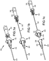
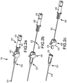
- Figs. 1a to 3d show an example embodiment of a safety catheter assembly 100 that includes a catheter 200, an insertion needle assembly 300, and a needle tip protector assembly 400.
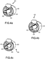
- the catheter 200, insertion needle assembly 300, and needle tip protector assembly 400 are shown in each of the ready position ( Figs. 1a , 2a , and 3a ), the safe position ( Figs. 1b , 2b , and 3b ), and the release position ( Figs. 1c , 2c , 3c, and 3d ), according to one example embodiment.
- Figs. 1a-1c and 2a-2c show the safety catheter assembly 100 in a perspective view taken from distal and proximal vantages, respectively.
- Figs. 3a-3d are cross sectional views of a portion of the catheter assembly.
- the catheter includes a catheter hub 202 and a catheter tube 204 that cooperate to provide a fluid pathway to the vein of a subject and other IV fluid components, such as an IV fluid supply.
- the catheter tube 204 includes a distal end, a proximal end, and a lumen extending therebetween.
- the proximal end of the catheter tube 204 is connected to a distal portion of the catheter hub 202.
- a proximal end 206 of the catheter hub is constructed and arranged to connect to other IV fluid components and may be designed in accordance with ISO standards, according to some embodiments.
- the proximal end of the catheter hub includes luer lugs, although other constructions are also contemplated.
- the insertion needle assembly 300 includes an insertion needle 302 having a sharp tip 304 that may create an entry passageway into the vein of a subject.
- the insertion needle extends from a sharp distal tip 304 to a proximal portion that is connected to a needle hub 306, and defines an internal lumen that extends therebetween.
- the proximal portion of the insertion needle is connected to and in fluid communication with the needle hub 306.
- the needle hub is connected to the flash plug 308 to allow blood to flow from the needle tip to the flash plug.
- the flash plug may 308 include a microporous barrier that permits the escape of air but prevents the escape of fluid.
- the body of the insertion needle may include a transition or bump 310 that interacts with the needle tip protector to move the catheter assembly between the ready, safe, and released positions, according to some embodiments.
- the illustrated example embodiment also includes a needle tip protector.
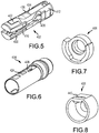
- the tip protector 400 includes an inner member 402, an outer member 404, a retainer 406, and a collar 408, each of which is shown separately in Figs. 5 to 8 .
- the inner member 402 and the outer member 404 of the tip protector cooperate to prevent access to the needle tip 304 in the safe and released positions.
- the retainer 406 and the collar 408 cooperate to secure the catheter 200 to the tip protector assembly 400 in each of the ready and safe positions, while enabling release of the catheter in the release position.
- the transition or bump 310 on the body of the needle 302 acts move the tip protector 400 between the ready, safe, and release positions and may also prevent separation of the insertion needle assembly 300 from the tip protector assembly 400.
- the inner member 402 of the tip protector 404 includes distal arms 410, a proximal base 412, and a bump washer 414.
- the bump washer 414 defines a proximal needle stop 416 and a proximal opening 418 that allows passage of the needle 302 but not the bump 310.
- the transition 310 contacts the proximal needle stop 416 to prevent the transition 310 from passing through the proximal opening 418, thus preventing separation of the insertion needle assembly 300 from the tip protector 400.
- the proximal needle stop 416 is formed in a bump washer 414 that is assembled to the proximal end of the inner member 402.
- the bump washer 414 is shaped generally like a traditional washer with the inclusion of a distally extending arm 420 that facilitates connection to other portions of the inner member.
- the bump washer may be made of a rigid material, such as a metal or plastic that resists deformation when contacted by the transition of the insertion needle. It is to be appreciated that proximal stops, according to alternate example embodiments, may be formed directly in the retainer or in different types of bump washers, such as bump washers that lack a distally extending tab or that are made of materials other than metal.
- the transition 310 may be located on the needle 302 so that the needle tip 304 is positioned within the inner member 402 of the tip protector 400 when the transition contacts the proximal stop 416, such that access to the needle tip may be prevented. This may generally be accomplished by locating the transition 310 a distance from the needle tip 304 that is less than the distance between the proximal stop 416 and the distal end 422 of the inner member 402. According to some embodiments, the distance between the transition and the needle tip may be smaller than a distance between the proximal stop and a distal stop on the inner member. It is to be appreciated, however, that other configurations are possible, including embodiments where the transition is located on the needle such that the needle tip is positioned internally to the outer member or another component of the tip protector.
- proximal movement of the insertion needle 302 causes the inner member 402 to move proximally relative to the outer member 404 from a distal inner member position to a proximal inner member position, as may be seen in the progression of movement between Figs. 3a and 3b .
- Movement of the inner member 402 within the outer member 404 causes arms 410 of the inner member to move into a restriction 424 of the outer member.
- Interaction between the arms 410 and the outer member 424 urges the arms toward one another, causes the arms to form a distal needle stop 426 in the passageway previously occupied by the insertion needle 302.
- the distal needle stop 426 prevents distal movement of the needle from outside of the interior of the inner member, and thus protects clinicians and others from the sharp needle tip.
- the arms of the inner member may include protrusions or ribs that engage one another to form the distal needle stop when the inner member is in the proximal inner member position, such as when the tip protector assembly is in either of the safe or release positions. These or other features of the arms may contact one another, fully occupying the needle passageway to form the distal needle stop, as shown in Fig. 3b . It is to be appreciated, however, that other embodiments may lack such fingers or ribs. It is also to be appreciated that the distal needle stop may not fully occupy the needle passageway when in the safe position, according to alternate embodiments. In one such alternate embodiment, the arms of the inner member are urged toward one another to form a distal needle stop that restricts passage of the sharp needle tip without fully occupying the needle passageway.
- the distal arms 410 of the inner member may be biased in the radially outward direction, away from one another. Such a bias may promote separation of the distal arms 410 from one another and thus from the insertion needle 302 prior to the needle reaching the safe position. Such separation may minimize friction between the insertion needle 302 and inner member 402, promoting easy movement of the insertion needle from the ready position to the safe position.
- the inner member is made of a resilient rubber or plastic material.
- the distal arms 410 may include a hinge area 428 near a connection to the proximal base 412 and an enlarged distal portion 430.
- the hinge area may promote flexing of the distal arms between the ready position and the safe position.
- the enlarged distal portions 430 may be shaped and sized to form the distal needle stop 426 when moved inwards or toward one another by the restriction 424 of the outer member.
- the distal portion of at least one of the arms includes a ramp structure 432 that interacts with the outer member 404 to urge the arm inward 410, toward the needle passageway, as the inner member is pulled proximally by movement of the insertion needle.
- the inner member includes a safe position lock 434 that prevents distal movement of the inner member, once in the inner member proximal position relative to the outer member.
- the lock 434 includes a distally facing inner member lock surface 436 that interacts with an inwardly biased tab 438 of the outer member 404. Proximal movement of the inner member 402 brings the lock surface into engagement with a proximally facing lock surface of the tab 438. Once engaged, the lock surfaces 436 of the inner member 402 and the tab 438 prevent emergence of the needle tip 304 by preventing the inner member 402 from returning to the distal inner member position.
- the safe position lock shown in the illustrated example embodiment is but one type of lock and that others are also contemplated.
- the catheter 200 in each of the ready and safe positions the catheter 200 is secured to the needle tip protector 400 in a manner that prevents separation, with the retainer 406 in a distal retainer position relative to the collar 408.
- This is accomplished by various engagement features in the needle tip protector 400 that secure the catheter 200 to the tip protector until the tip protector is in the release position.
- external engagement features are located on the collar and the retainer.
- the outer member may additionally provide internal engagement features that help to secure the catheter to the tip protector.
- the collar 408 includes a notch 440 that receives a first luer lug 208 of the catheter hub 202.
- the notch 440 engages a forward facing surface of the luer lug to prevent the lug and thus the catheter from moving distally away from the tip protector assembly. Contact between a notch and the first luer lug of the catheter may also prevent the catheter hub from moving laterally away from the tip protector.
- the retainer includes a base and a lateral wall that form a pocket that receives the proximal end of the catheter hub. Inner portions of the catheter wall engage corresponding outer surfaces of the catheter hub to secure the catheter to the tip protector assembly.
- the retainer is shown to have a pocket with a shape that corresponds to that of the proximal end of the catheter, it is to be appreciated that other configurations are also contemplated, such as configurations that engage the second luer lug of the catheter hub.
- the outer member of the needle tip protector assembly may, according to some embodiments, contact the interior of the catheter hub to provide an interior engagement.
- the outer member may be sized such that a sliding surface of the outer wall makes contact with the interior of the catheter hub. This contact may prevent the catheter hub from moving laterally with respect to the outer member and other portions of the tip protector without directly preventing distal movement of the catheter.
- the outer member may be shaped and sized such that there is no contact between the outer member and the catheter hub.
- the tip protector may include a feature that resists proximal movement of the retainer to the proximal release position prior to being in the safe position.
- the illustrated example embodiment includes a retention finger that is integrated into the collar and that includes a spring arm and a retention tab.
- the retention tab is positioned proximally to the retainer. Proximal movement of the retainer is resisted by the retention tab, until the forces associated with flexing the spring arm and retention tab away from the retainer are overcome.
- the retention tab 442 of the collar 408 provides a release threshold force that is to be overcome prior to the catheter 200 being released from the tip protection assembly 400.
- the release threshold force may be higher than the forces associated with movement from the ready position to the safe position (i.e., the safety threshold force), according to some embodiments. Having the release threshold force higher than the safe threshold force may prevent the catheter from being released prior to the tip protection assembly being moved to the safe position.
- the release threshold force is more than 2x the safety threshold force, more than 3x the safety threshold force, or more than 5x the safety threshold force.
- the catheter hub 202 is released from secure connection to the tip protection assembly 400 when the external engagement features of the retainer 406 are out of engagement with the catheter hub 202, as shown in Fig. 3c .
- the further proximal movement of the insertion needle assembly 300 will pull the needle tip protector 400 away from the catheter hub 202, as reflect in Fig. 3d .
- Separation of the collar 408 from the catheter hub 202 may be accompanied by a slight jogging of the tip protector in a lateral direction, away from the needle passage, according to some embodiments.
- the sloped shape of the luer lug and/or the notch may promote this motion.
- the clinician may tilt pull on the insertion needle assembly at an upward angle to promote separation of the catheter from the collar.
- the catheter hub may include a side port 500, such as in the example embodiment of Figures 9 and 10 .
- the catheter hub 202 includes a side port that may be accessed through a lateral, luer type connection that is integrated into the catheter hub.
- a side port cap 502 may be selectively positioned over the side port to close and open access thereto, as desired.
- a flexible, cylindrically shaped septum is positioned internally to the catheter hub. The septum 504 is moved away from the side port by pressurized fluid that is introduced into the luer to allow the pressurized fluid to enter the catheter hub. In the absence of pressurized fluid in the luer, the septum closes access to the side port to prevent the escape of fluids from the catheter.
- catheters are described herein for use in accessing the vein of a subject. It is to be appreciated, however, that the example embodiments described herein may alternately be used to access the vasculature of a subject at locations other than a vein, including but not limited to the artery of a subject. It is additionally to be appreciated that the term “clinician” refers to any individual that may be performing a catheter insertion procedure with any of the example embodiments described herein or combinations thereof. Similarly, the term “subject”, as used herein, is to be understood to refer to an individual or object in which a catheter is to be inserted, whether human, animal, or inanimate. Various descriptions are made herein, for the sake of convenience, with respect to procedures being performed by a clinician to access the vein of a subject, while the disclosure is not limited in this respect.
- distal refers to the direction, taking along an axis that lies parallel to the needle of a safety catheter assembly that is closest to a subject during catheter insertion.
- proximal refers the direction lying along the axis parallel to the needle that is farther away from the subject when the catheter is inserted into the vein of the subject - that is, opposite to the distal direction.
Landscapes
- Health & Medical Sciences (AREA)
- Life Sciences & Earth Sciences (AREA)
- Biomedical Technology (AREA)
- Pulmonology (AREA)
- Engineering & Computer Science (AREA)
- Anesthesiology (AREA)
- Biophysics (AREA)
- Heart & Thoracic Surgery (AREA)
- Hematology (AREA)
- Animal Behavior & Ethology (AREA)
- General Health & Medical Sciences (AREA)
- Public Health (AREA)
- Veterinary Medicine (AREA)
- Infusion, Injection, And Reservoir Apparatuses (AREA)
- Media Introduction/Drainage Providing Device (AREA)
Claims (13)
- Cathéter de sécurité, comprenant :un cathéter (200) incluant un tube de cathéter (204) et un raccord de cathéter (202) ;un dispositif d'insertion de cathéter incluant une aiguille d'insertion (302) et un ensemble de protection de la pointe (400) connecté de manière opérationnelle à l'aiguille d'insertion (302), l'aiguille d'insertion (302) comportant une pointe acérée (304), une extrémité proximale et une transition d'aiguille (310) sur le corps de l'aiguille et espacée de la pointe acérée (304) d'une distance de transition, l'ensemble de protection de la pointe (400) comportant un élément interne (402), un élément externe (404), un élément de retenue (406) et un collier (408), l'élément interne (402) pouvant être déplacé entre une position distale de l'élément interne et une position proximale de l'élément interne par rapport à l'élément externe (404), et l'élément de retenue (406) pouvant être déplacé entre une position distale de l'élément de retenue et une position proximale de l'élément de retenue par rapport au collier (408), l'ensemble de protection de la pointe (400) pouvant être déplacé entre trois positions de fonctionnement incluant une position d'utilisation, une position de sécurité et une position de libération ;dans lequel, dans la position d'utilisation, au moins une partie de l'aiguille d'insertion (302) est positionnée à l'intérieur du tube du cathéter (204), l'élément interne (402) se trouvant dans la position distale de l'élément interne par rapport à l'élément externe (404), l'élément de retenue (406) se trouvant dans la position distale de l'élément de retenue par rapport au collier (408), l'élément de retenue (406) et le collier (408) s'engageant dans le raccord du cathéter (202) pour empêcher la libération du raccord du cathéter (202) du dispositif d'insertion de cathéter ;dans lequel, dans la position de sécurité, l'élément interne (402) se trouve dans la position proximale de l'élément interne par rapport à l'élément externe (404), la pointe acérée (304) de l'aiguille d'insertion (302) étant positionnée à l'intérieur de l'ensemble de protection de la pointe (400), l'élément de retenue (406) se trouvant dans la position distale de l'élément de retenue par rapport au collier (408), l'élément de retenue (406) et le collier (408) s'engageant dans le raccord du cathéter (202) pour empêcher la libération du raccord du cathéter (202) du dispositif d'insertion de cathéter ; etdans lequel, dans la position de libération, l'élément interne (402) se trouve dans la position proximale de l'élément interne par rapport à l'élément externe (404), la pointe acérée (304) de l'aiguille d'insertion (302) étant positionnée à l'intérieur de l'ensemble de protection de la pointe (400), et l'élément de retenue (406) se trouvant dans la position proximale de l'élément de retenue par rapport au collier (408) pour permettre la libération du raccord du cathéter (202) du dispositif d'insertion de cathéter.
- Cathéter de sécurité selon la revendication 1, dans lequel l'ensemble de protection de la pointe (400) se déplace de la position d'utilisation vers la position de sécurité, et ensuite vers la position de libération au cours d'un retrait de l'aiguille d'insertion (302) du cathéter (200).
- Cathéter de sécurité selon la revendication 2, dans lequel une interaction entre la transition de l'aiguille (310) et une butée proximale (416) de l'élément interne (402) au cours du retrait de l'aiguille d'insertion (302) entraîne le déplacement de l'élément interne (402) de la position distale de l'élément interne vers la position proximale de l'élément interne par rapport à l'élément externe (404), pour placer l'ensemble de protection de la pointe (400) dans la position de sécurité.
- Cathéter de sécurité selon la revendication 3, dans lequel, après que l'élément interne (402) a atteint la position proximale de l'élément interne, un retrait additionnel de l'aiguille d'insertion (302) entraîne le déplacement de l'élément de retenue (406) par la transition d'aiguille (310) de la position distale de l'élément de retenue vers la position proximale de l'élément de retenue par rapport au collier (408) pour placer l'ensemble de protection de la pointe (400) dans la position de libération.
- Cathéter de sécurité selon la revendication 4, dans lequel l'élément interne (402) a une longueur entre une extrémité distale (422) de l'élément interne (402) et la butée proximale (416) qui est supérieure à la distance de transition.
- Cathéter de sécurité selon la revendication 5, dans lequel l'élément interne (402) inclut un verrou de position de sécurité (434) empêchant un déplacement distal par rapport à l'élément externe (404) lorsque l'élément interne (402) se trouve dans la position proximale de l'élément interne.
- Cathéter de sécurité selon la revendication 6, dans lequel l'élément interne (402) inclut une rondelle métallique (414) empêchant le passage proximal de la transition (310) et de la pointe acérée (304) à partir de l'ensemble de protection de la pointe (400), et des bras (410) se déplaçant radialement vers l'intérieur lorsque l'élément interne (402) se trouve dans la position proximale de l'élément interne pour établir une butée distale (426) empêchant le déplacement distal de la pointe acérée (304) à partir de l'ensemble de protection de la pointe (400).
- Cathéter de sécurité selon la revendication 7, dans lequel le raccord du cathéter (202) est retenu sur l'ensemble de protection de la pointe (400) au moins par un engagement entre des structures d'engagement externes du raccord du cathéter (202) et du collier (408) et de l'élément de retenue (406) lorsque l'ensemble de protection de la pointe (400) se trouve dans la position de sécurité, et dans lequel un déplacement de l'élément de retenue (406) vers la position proximale de l'élément de retenue permet une libération du cathéter (200) de l'ensemble de protection de la pointe (400).
- Cathéter de sécurité selon la revendication 8, dans lequel l'élément de retenue (406) est connecté de manière fixe à l'élément externe (404), et l'élément externe (404) se déplace avec l'élément de retenue (406) de la position distale de l'élément de retenue vers la position proximale de l'élément de retenue.
- Cathéter de sécurité selon la revendication 9, dans lequel le raccord du cathéter (202) est en outre retenu sur l'ensemble de protection de la pointe (400) par l'engagement entre des parties internes du raccord du cathéter (202) et l'élément externe (404) lorsque l'ensemble de protection de la pointe (400) se trouve dans la position de sécurité.
- Cathéter de sécurité selon la revendication 3, dans lequel un déplacement de l'ensemble de protection de la pointe (400) de la position d'utilisation vers la position de sécurité est associé à un dépassement d'une force de seuil de sécurité au cours du retrait de l'aiguille, et dans lequel un déplacement de l'ensemble de protection de la pointe (400) de la position de sécurité vers la position de libération est en outre associé au dépassement d'une force de seuil de libération au cours du retrait de l'aiguille, la force de seuil de libération étant supérieure à la force de seuil de sécurité.
- Cathéter de sécurité selon la revendication 11, dans lequel le collier (408) inclut un doigt de retenue qui résiste au déplacement de l'élément de retenue (406) vers la position proximale de l'élément de retenue.
- Cathéter de sécurité selon la revendication 1, dans lequel le cathéter (200) comprend en outre un orifice latéral (500).
Priority Applications (1)
| Application Number | Priority Date | Filing Date | Title |
|---|---|---|---|
| EP21155603.0A EP3854439B1 (fr) | 2017-03-23 | 2018-03-21 | Cathéter de sécurité à libération passive |
Applications Claiming Priority (2)
| Application Number | Priority Date | Filing Date | Title |
|---|---|---|---|
| US201762475428P | 2017-03-23 | 2017-03-23 | |
| PCT/US2018/023550 WO2018175573A1 (fr) | 2017-03-23 | 2018-03-21 | Cathéter de sécurité à libération passive |
Related Child Applications (2)
| Application Number | Title | Priority Date | Filing Date |
|---|---|---|---|
| EP21155603.0A Division EP3854439B1 (fr) | 2017-03-23 | 2018-03-21 | Cathéter de sécurité à libération passive |
| EP21155603.0A Division-Into EP3854439B1 (fr) | 2017-03-23 | 2018-03-21 | Cathéter de sécurité à libération passive |
Publications (3)
| Publication Number | Publication Date |
|---|---|
| EP3568189A1 EP3568189A1 (fr) | 2019-11-20 |
| EP3568189A4 EP3568189A4 (fr) | 2020-02-19 |
| EP3568189B1 true EP3568189B1 (fr) | 2021-04-21 |
Family
ID=63586203
Family Applications (2)
| Application Number | Title | Priority Date | Filing Date |
|---|---|---|---|
| EP21155603.0A Active EP3854439B1 (fr) | 2017-03-23 | 2018-03-21 | Cathéter de sécurité à libération passive |
| EP18771336.7A Active EP3568189B1 (fr) | 2017-03-23 | 2018-03-21 | Cathéter de sécurité à libération passive |
Family Applications Before (1)
| Application Number | Title | Priority Date | Filing Date |
|---|---|---|---|
| EP21155603.0A Active EP3854439B1 (fr) | 2017-03-23 | 2018-03-21 | Cathéter de sécurité à libération passive |
Country Status (3)
| Country | Link |
|---|---|
| US (4) | US10543341B2 (fr) |
| EP (2) | EP3854439B1 (fr) |
| WO (1) | WO2018175573A1 (fr) |
Families Citing this family (2)
| Publication number | Priority date | Publication date | Assignee | Title |
|---|---|---|---|---|
| US12508403B2 (en) * | 2019-04-23 | 2025-12-30 | ICU Medical. Inc. | Catheter insertion device with improved push tab and tip protector assembly |
| CN112546339A (zh) * | 2019-09-10 | 2021-03-26 | 贝克顿·迪金森公司 | 一种血管通路系统、血液采集方法及夹紧夹装置 |
Family Cites Families (7)
| Publication number | Priority date | Publication date | Assignee | Title |
|---|---|---|---|---|
| US6595954B1 (en) | 2000-03-13 | 2003-07-22 | Luther Research Partners, Llc | Insertion needle and soft catheter system with tip protector |
| US20070038183A1 (en) | 2005-08-08 | 2007-02-15 | Bialecki Dennis M | Needle guard clip with stylus |
| US8398597B2 (en) * | 2008-06-17 | 2013-03-19 | Becton, Dickinson And Company | Needle shield and interlock |
| US8257322B2 (en) | 2010-06-02 | 2012-09-04 | Smiths Medical Asd, Inc. | Tip protector for a safety catheter |
| WO2014162377A1 (fr) | 2013-04-01 | 2014-10-09 | テルモ株式会社 | Ensemble sonde |
| WO2014196243A1 (fr) * | 2013-06-06 | 2014-12-11 | テルモ株式会社 | Ensemble cathéter |
| US9555221B2 (en) * | 2014-04-10 | 2017-01-31 | Smiths Medical Asd, Inc. | Constant force hold tip protector for a safety catheter |
-
2018
- 2018-03-21 EP EP21155603.0A patent/EP3854439B1/fr active Active
- 2018-03-21 EP EP18771336.7A patent/EP3568189B1/fr active Active
- 2018-03-21 WO PCT/US2018/023550 patent/WO2018175573A1/fr not_active Ceased
- 2018-03-21 US US16/065,578 patent/US10543341B2/en active Active
-
2019
- 2019-12-17 US US16/717,063 patent/US11590324B2/en active Active
-
2023
- 2023-01-12 US US18/096,149 patent/US11931533B2/en active Active
-
2024
- 2024-02-08 US US18/436,203 patent/US12274840B2/en active Active
Non-Patent Citations (1)
| Title |
|---|
| None * |
Also Published As
| Publication number | Publication date |
|---|---|
| US20240181220A1 (en) | 2024-06-06 |
| EP3854439A1 (fr) | 2021-07-28 |
| US11931533B2 (en) | 2024-03-19 |
| US20200121895A1 (en) | 2020-04-23 |
| WO2018175573A1 (fr) | 2018-09-27 |
| US10543341B2 (en) | 2020-01-28 |
| US11590324B2 (en) | 2023-02-28 |
| US12274840B2 (en) | 2025-04-15 |
| US20230149666A1 (en) | 2023-05-18 |
| EP3568189A4 (fr) | 2020-02-19 |
| EP3568189A1 (fr) | 2019-11-20 |
| US20190374749A1 (en) | 2019-12-12 |
| EP3854439B1 (fr) | 2022-04-06 |
Similar Documents
| Publication | Publication Date | Title |
|---|---|---|
| US20260091202A1 (en) | Releasable safety catheter insertion assembly | |
| JP7385552B2 (ja) | 外部針シールドおよび内部血液制御隔壁を有するポート付きivカテーテル | |
| US12150765B2 (en) | Releaseable catheter hub retainer | |
| EP3250280B1 (fr) | Dispositif de retenue d'embase de cathéter amovible | |
| CA2728010C (fr) | Gaine d'aiguille telescopique avec verrouillage | |
| CN111032136A (zh) | 用于进入血管的方法和装置 | |
| AU2020286296B2 (en) | Blood containment for IV catheter | |
| BRPI1012701B1 (pt) | mecanismo de proteção de ponta de agulha, montagem de cateter e método para usar um mecanismo de proteção de ponta de agulha | |
| WO2014140265A1 (fr) | Ensembles cathéters à valve | |
| EP2736575A1 (fr) | Ensemble accès vasculaire et dispositif de sécurité | |
| US12274840B2 (en) | Safety catheter with passive release | |
| EP1292355B1 (fr) | Ensemble catheter et aiguille d'introduction pourvu d'une protection d'aiguille | |
| JP7817180B2 (ja) | 針ガード付き静脈内デバイスアセンブリ | |
| US8192404B2 (en) | Indwelling needle assembly | |
| SG173383A1 (en) | Catheter and introducer needle assembly with safety device | |
| JP7418627B2 (ja) | 再使用防止安全カテーテル |
Legal Events
| Date | Code | Title | Description |
|---|---|---|---|
| STAA | Information on the status of an ep patent application or granted ep patent |
Free format text: STATUS: THE INTERNATIONAL PUBLICATION HAS BEEN MADE |
|
| PUAI | Public reference made under article 153(3) epc to a published international application that has entered the european phase |
Free format text: ORIGINAL CODE: 0009012 |
|
| STAA | Information on the status of an ep patent application or granted ep patent |
Free format text: STATUS: REQUEST FOR EXAMINATION WAS MADE |
|
| 17P | Request for examination filed |
Effective date: 20190815 |
|
| AK | Designated contracting states |
Kind code of ref document: A1 Designated state(s): AL AT BE BG CH CY CZ DE DK EE ES FI FR GB GR HR HU IE IS IT LI LT LU LV MC MK MT NL NO PL PT RO RS SE SI SK SM TR |
|
| AX | Request for extension of the european patent |
Extension state: BA ME |
|
| A4 | Supplementary search report drawn up and despatched |
Effective date: 20200120 |
|
| RIC1 | Information provided on ipc code assigned before grant |
Ipc: A61M 25/06 20060101AFI20200114BHEP |
|
| DAV | Request for validation of the european patent (deleted) | ||
| DAX | Request for extension of the european patent (deleted) | ||
| GRAP | Despatch of communication of intention to grant a patent |
Free format text: ORIGINAL CODE: EPIDOSNIGR1 |
|
| STAA | Information on the status of an ep patent application or granted ep patent |
Free format text: STATUS: GRANT OF PATENT IS INTENDED |
|
| INTG | Intention to grant announced |
Effective date: 20201204 |
|
| GRAS | Grant fee paid |
Free format text: ORIGINAL CODE: EPIDOSNIGR3 |
|
| GRAA | (expected) grant |
Free format text: ORIGINAL CODE: 0009210 |
|
| STAA | Information on the status of an ep patent application or granted ep patent |
Free format text: STATUS: THE PATENT HAS BEEN GRANTED |
|
| AK | Designated contracting states |
Kind code of ref document: B1 Designated state(s): AL AT BE BG CH CY CZ DE DK EE ES FI FR GB GR HR HU IE IS IT LI LT LU LV MC MK MT NL NO PL PT RO RS SE SI SK SM TR |
|
| REG | Reference to a national code |
Ref country code: GB Ref legal event code: FG4D |
|
| REG | Reference to a national code |
Ref country code: CH Ref legal event code: EP |
|
| REG | Reference to a national code |
Ref country code: DE Ref legal event code: R096 Ref document number: 602018015963 Country of ref document: DE Ref country code: IE Ref legal event code: FG4D |
|
| REG | Reference to a national code |
Ref country code: AT Ref legal event code: REF Ref document number: 1383992 Country of ref document: AT Kind code of ref document: T Effective date: 20210515 |
|
| REG | Reference to a national code |
Ref country code: LT Ref legal event code: MG9D |
|
| REG | Reference to a national code |
Ref country code: AT Ref legal event code: MK05 Ref document number: 1383992 Country of ref document: AT Kind code of ref document: T Effective date: 20210421 |
|
| REG | Reference to a national code |
Ref country code: NL Ref legal event code: MP Effective date: 20210421 |
|
| PG25 | Lapsed in a contracting state [announced via postgrant information from national office to epo] |
Ref country code: FI Free format text: LAPSE BECAUSE OF FAILURE TO SUBMIT A TRANSLATION OF THE DESCRIPTION OR TO PAY THE FEE WITHIN THE PRESCRIBED TIME-LIMIT Effective date: 20210421 Ref country code: HR Free format text: LAPSE BECAUSE OF FAILURE TO SUBMIT A TRANSLATION OF THE DESCRIPTION OR TO PAY THE FEE WITHIN THE PRESCRIBED TIME-LIMIT Effective date: 20210421 Ref country code: LT Free format text: LAPSE BECAUSE OF FAILURE TO SUBMIT A TRANSLATION OF THE DESCRIPTION OR TO PAY THE FEE WITHIN THE PRESCRIBED TIME-LIMIT Effective date: 20210421 Ref country code: NL Free format text: LAPSE BECAUSE OF FAILURE TO SUBMIT A TRANSLATION OF THE DESCRIPTION OR TO PAY THE FEE WITHIN THE PRESCRIBED TIME-LIMIT Effective date: 20210421 Ref country code: BG Free format text: LAPSE BECAUSE OF FAILURE TO SUBMIT A TRANSLATION OF THE DESCRIPTION OR TO PAY THE FEE WITHIN THE PRESCRIBED TIME-LIMIT Effective date: 20210721 Ref country code: AT Free format text: LAPSE BECAUSE OF FAILURE TO SUBMIT A TRANSLATION OF THE DESCRIPTION OR TO PAY THE FEE WITHIN THE PRESCRIBED TIME-LIMIT Effective date: 20210421 |
|
| PG25 | Lapsed in a contracting state [announced via postgrant information from national office to epo] |
Ref country code: IS Free format text: LAPSE BECAUSE OF FAILURE TO SUBMIT A TRANSLATION OF THE DESCRIPTION OR TO PAY THE FEE WITHIN THE PRESCRIBED TIME-LIMIT Effective date: 20210821 Ref country code: GR Free format text: LAPSE BECAUSE OF FAILURE TO SUBMIT A TRANSLATION OF THE DESCRIPTION OR TO PAY THE FEE WITHIN THE PRESCRIBED TIME-LIMIT Effective date: 20210722 Ref country code: PL Free format text: LAPSE BECAUSE OF FAILURE TO SUBMIT A TRANSLATION OF THE DESCRIPTION OR TO PAY THE FEE WITHIN THE PRESCRIBED TIME-LIMIT Effective date: 20210421 Ref country code: NO Free format text: LAPSE BECAUSE OF FAILURE TO SUBMIT A TRANSLATION OF THE DESCRIPTION OR TO PAY THE FEE WITHIN THE PRESCRIBED TIME-LIMIT Effective date: 20210721 Ref country code: LV Free format text: LAPSE BECAUSE OF FAILURE TO SUBMIT A TRANSLATION OF THE DESCRIPTION OR TO PAY THE FEE WITHIN THE PRESCRIBED TIME-LIMIT Effective date: 20210421 Ref country code: RS Free format text: LAPSE BECAUSE OF FAILURE TO SUBMIT A TRANSLATION OF THE DESCRIPTION OR TO PAY THE FEE WITHIN THE PRESCRIBED TIME-LIMIT Effective date: 20210421 Ref country code: PT Free format text: LAPSE BECAUSE OF FAILURE TO SUBMIT A TRANSLATION OF THE DESCRIPTION OR TO PAY THE FEE WITHIN THE PRESCRIBED TIME-LIMIT Effective date: 20210823 Ref country code: SE Free format text: LAPSE BECAUSE OF FAILURE TO SUBMIT A TRANSLATION OF THE DESCRIPTION OR TO PAY THE FEE WITHIN THE PRESCRIBED TIME-LIMIT Effective date: 20210421 |
|
| REG | Reference to a national code |
Ref country code: DE Ref legal event code: R097 Ref document number: 602018015963 Country of ref document: DE |
|
| PG25 | Lapsed in a contracting state [announced via postgrant information from national office to epo] |
Ref country code: SM Free format text: LAPSE BECAUSE OF FAILURE TO SUBMIT A TRANSLATION OF THE DESCRIPTION OR TO PAY THE FEE WITHIN THE PRESCRIBED TIME-LIMIT Effective date: 20210421 Ref country code: RO Free format text: LAPSE BECAUSE OF FAILURE TO SUBMIT A TRANSLATION OF THE DESCRIPTION OR TO PAY THE FEE WITHIN THE PRESCRIBED TIME-LIMIT Effective date: 20210421 Ref country code: CZ Free format text: LAPSE BECAUSE OF FAILURE TO SUBMIT A TRANSLATION OF THE DESCRIPTION OR TO PAY THE FEE WITHIN THE PRESCRIBED TIME-LIMIT Effective date: 20210421 Ref country code: DK Free format text: LAPSE BECAUSE OF FAILURE TO SUBMIT A TRANSLATION OF THE DESCRIPTION OR TO PAY THE FEE WITHIN THE PRESCRIBED TIME-LIMIT Effective date: 20210421 Ref country code: SK Free format text: LAPSE BECAUSE OF FAILURE TO SUBMIT A TRANSLATION OF THE DESCRIPTION OR TO PAY THE FEE WITHIN THE PRESCRIBED TIME-LIMIT Effective date: 20210421 Ref country code: ES Free format text: LAPSE BECAUSE OF FAILURE TO SUBMIT A TRANSLATION OF THE DESCRIPTION OR TO PAY THE FEE WITHIN THE PRESCRIBED TIME-LIMIT Effective date: 20210421 Ref country code: EE Free format text: LAPSE BECAUSE OF FAILURE TO SUBMIT A TRANSLATION OF THE DESCRIPTION OR TO PAY THE FEE WITHIN THE PRESCRIBED TIME-LIMIT Effective date: 20210421 |
|
| PLBE | No opposition filed within time limit |
Free format text: ORIGINAL CODE: 0009261 |
|
| STAA | Information on the status of an ep patent application or granted ep patent |
Free format text: STATUS: NO OPPOSITION FILED WITHIN TIME LIMIT |
|
| 26N | No opposition filed |
Effective date: 20220124 |
|
| PG25 | Lapsed in a contracting state [announced via postgrant information from national office to epo] |
Ref country code: IS Free format text: LAPSE BECAUSE OF FAILURE TO SUBMIT A TRANSLATION OF THE DESCRIPTION OR TO PAY THE FEE WITHIN THE PRESCRIBED TIME-LIMIT Effective date: 20210821 Ref country code: AL Free format text: LAPSE BECAUSE OF FAILURE TO SUBMIT A TRANSLATION OF THE DESCRIPTION OR TO PAY THE FEE WITHIN THE PRESCRIBED TIME-LIMIT Effective date: 20210421 |
|
| PG25 | Lapsed in a contracting state [announced via postgrant information from national office to epo] |
Ref country code: MC Free format text: LAPSE BECAUSE OF FAILURE TO SUBMIT A TRANSLATION OF THE DESCRIPTION OR TO PAY THE FEE WITHIN THE PRESCRIBED TIME-LIMIT Effective date: 20210421 |
|
| REG | Reference to a national code |
Ref country code: CH Ref legal event code: PL |
|
| REG | Reference to a national code |
Ref country code: BE Ref legal event code: MM Effective date: 20220331 |
|
| PG25 | Lapsed in a contracting state [announced via postgrant information from national office to epo] |
Ref country code: LU Free format text: LAPSE BECAUSE OF NON-PAYMENT OF DUE FEES Effective date: 20220321 Ref country code: IE Free format text: LAPSE BECAUSE OF NON-PAYMENT OF DUE FEES Effective date: 20220321 Ref country code: CH Free format text: LAPSE BECAUSE OF NON-PAYMENT OF DUE FEES Effective date: 20220331 Ref country code: LI Free format text: LAPSE BECAUSE OF NON-PAYMENT OF DUE FEES Effective date: 20220331 |
|
| PG25 | Lapsed in a contracting state [announced via postgrant information from national office to epo] |
Ref country code: BE Free format text: LAPSE BECAUSE OF NON-PAYMENT OF DUE FEES Effective date: 20220331 |
|
| P01 | Opt-out of the competence of the unified patent court (upc) registered |
Effective date: 20230419 |
|
| PG25 | Lapsed in a contracting state [announced via postgrant information from national office to epo] |
Ref country code: MK Free format text: LAPSE BECAUSE OF FAILURE TO SUBMIT A TRANSLATION OF THE DESCRIPTION OR TO PAY THE FEE WITHIN THE PRESCRIBED TIME-LIMIT Effective date: 20210421 Ref country code: CY Free format text: LAPSE BECAUSE OF FAILURE TO SUBMIT A TRANSLATION OF THE DESCRIPTION OR TO PAY THE FEE WITHIN THE PRESCRIBED TIME-LIMIT Effective date: 20210421 |
|
| PG25 | Lapsed in a contracting state [announced via postgrant information from national office to epo] |
Ref country code: HU Free format text: LAPSE BECAUSE OF FAILURE TO SUBMIT A TRANSLATION OF THE DESCRIPTION OR TO PAY THE FEE WITHIN THE PRESCRIBED TIME-LIMIT; INVALID AB INITIO Effective date: 20180321 |
|
| PG25 | Lapsed in a contracting state [announced via postgrant information from national office to epo] |
Ref country code: TR Free format text: LAPSE BECAUSE OF FAILURE TO SUBMIT A TRANSLATION OF THE DESCRIPTION OR TO PAY THE FEE WITHIN THE PRESCRIBED TIME-LIMIT Effective date: 20210421 |
|
| PG25 | Lapsed in a contracting state [announced via postgrant information from national office to epo] |
Ref country code: MT Free format text: LAPSE BECAUSE OF FAILURE TO SUBMIT A TRANSLATION OF THE DESCRIPTION OR TO PAY THE FEE WITHIN THE PRESCRIBED TIME-LIMIT Effective date: 20210421 |
|
| REG | Reference to a national code |
Ref country code: GB Ref legal event code: 732E Free format text: REGISTERED BETWEEN 20240919 AND 20240925 |
|
| REG | Reference to a national code |
Ref country code: DE Ref legal event code: R082 Ref document number: 602018015963 Country of ref document: DE Representative=s name: CHARRIER RAPP & LIEBAU PATENTANWAELTE PARTG MB, DE Ref country code: DE Ref legal event code: R081 Ref document number: 602018015963 Country of ref document: DE Owner name: ICU MEDICAL, INC., SAN CLEMENTE, US Free format text: FORMER OWNER: SMITHS MEDICAL ASD, INC., PLYMOUTH, MN, US |
|
| PGFP | Annual fee paid to national office [announced via postgrant information from national office to epo] |
Ref country code: FR Payment date: 20251231 Year of fee payment: 9 |
|
| PGFP | Annual fee paid to national office [announced via postgrant information from national office to epo] |
Ref country code: GB Payment date: 20260106 Year of fee payment: 9 |
|
| PGFP | Annual fee paid to national office [announced via postgrant information from national office to epo] |
Ref country code: DE Payment date: 20260102 Year of fee payment: 9 |
|
| PGFP | Annual fee paid to national office [announced via postgrant information from national office to epo] |
Ref country code: IT Payment date: 20260220 Year of fee payment: 9 |