EP3568199B1 - Abschwächung des zusammenwirkeffektes bei der teilchenstrahlentherapie - Google Patents
Abschwächung des zusammenwirkeffektes bei der teilchenstrahlentherapie Download PDFInfo
- Publication number
- EP3568199B1 EP3568199B1 EP18738677.6A EP18738677A EP3568199B1 EP 3568199 B1 EP3568199 B1 EP 3568199B1 EP 18738677 A EP18738677 A EP 18738677A EP 3568199 B1 EP3568199 B1 EP 3568199B1
- Authority
- EP
- European Patent Office
- Prior art keywords
- spot
- repaintings
- period
- layer
- scan
- Prior art date
- Legal status (The legal status is an assumption and is not a legal conclusion. Google has not performed a legal analysis and makes no representation as to the accuracy of the status listed.)
- Active
Links
Images







Classifications
-
- A—HUMAN NECESSITIES
- A61—MEDICAL OR VETERINARY SCIENCE; HYGIENE
- A61N—ELECTROTHERAPY; MAGNETOTHERAPY; RADIATION THERAPY; ULTRASOUND THERAPY
- A61N5/00—Radiation therapy
- A61N5/10—X-ray therapy; Gamma-ray therapy; Particle-irradiation therapy
- A61N5/1048—Monitoring, verifying, controlling systems and methods
- A61N5/1064—Monitoring, verifying, controlling systems and methods for adjusting radiation treatment in response to monitoring
- A61N5/1068—Gating the beam as a function of a physiological signal
-
- A—HUMAN NECESSITIES
- A61—MEDICAL OR VETERINARY SCIENCE; HYGIENE
- A61N—ELECTROTHERAPY; MAGNETOTHERAPY; RADIATION THERAPY; ULTRASOUND THERAPY
- A61N5/00—Radiation therapy
- A61N5/10—X-ray therapy; Gamma-ray therapy; Particle-irradiation therapy
- A61N5/1048—Monitoring, verifying, controlling systems and methods
- A61N5/1064—Monitoring, verifying, controlling systems and methods for adjusting radiation treatment in response to monitoring
- A61N5/1065—Beam adjustment
- A61N5/1067—Beam adjustment in real time, i.e. during treatment
-
- A—HUMAN NECESSITIES
- A61—MEDICAL OR VETERINARY SCIENCE; HYGIENE
- A61N—ELECTROTHERAPY; MAGNETOTHERAPY; RADIATION THERAPY; ULTRASOUND THERAPY
- A61N5/00—Radiation therapy
-
- A—HUMAN NECESSITIES
- A61—MEDICAL OR VETERINARY SCIENCE; HYGIENE
- A61N—ELECTROTHERAPY; MAGNETOTHERAPY; RADIATION THERAPY; ULTRASOUND THERAPY
- A61N5/00—Radiation therapy
- A61N5/10—X-ray therapy; Gamma-ray therapy; Particle-irradiation therapy
- A61N5/103—Treatment planning systems
- A61N5/1037—Treatment planning systems taking into account the movement of the target, e.g. 4D-image based planning
-
- A—HUMAN NECESSITIES
- A61—MEDICAL OR VETERINARY SCIENCE; HYGIENE
- A61N—ELECTROTHERAPY; MAGNETOTHERAPY; RADIATION THERAPY; ULTRASOUND THERAPY
- A61N5/00—Radiation therapy
- A61N5/10—X-ray therapy; Gamma-ray therapy; Particle-irradiation therapy
- A61N5/103—Treatment planning systems
- A61N5/1039—Treatment planning systems using functional images, e.g. PET or MRI
-
- A—HUMAN NECESSITIES
- A61—MEDICAL OR VETERINARY SCIENCE; HYGIENE
- A61N—ELECTROTHERAPY; MAGNETOTHERAPY; RADIATION THERAPY; ULTRASOUND THERAPY
- A61N5/00—Radiation therapy
- A61N5/10—X-ray therapy; Gamma-ray therapy; Particle-irradiation therapy
- A61N5/1042—X-ray therapy; Gamma-ray therapy; Particle-irradiation therapy with spatial modulation of the radiation beam within the treatment head
- A61N5/1043—Scanning the radiation beam, e.g. spot scanning or raster scanning
-
- A—HUMAN NECESSITIES
- A61—MEDICAL OR VETERINARY SCIENCE; HYGIENE
- A61N—ELECTROTHERAPY; MAGNETOTHERAPY; RADIATION THERAPY; ULTRASOUND THERAPY
- A61N5/00—Radiation therapy
- A61N5/10—X-ray therapy; Gamma-ray therapy; Particle-irradiation therapy
- A61N5/1042—X-ray therapy; Gamma-ray therapy; Particle-irradiation therapy with spatial modulation of the radiation beam within the treatment head
- A61N5/1043—Scanning the radiation beam, e.g. spot scanning or raster scanning
- A61N5/1044—Scanning the radiation beam, e.g. spot scanning or raster scanning with multiple repetitions of the scanning pattern
-
- A—HUMAN NECESSITIES
- A61—MEDICAL OR VETERINARY SCIENCE; HYGIENE
- A61N—ELECTROTHERAPY; MAGNETOTHERAPY; RADIATION THERAPY; ULTRASOUND THERAPY
- A61N5/00—Radiation therapy
- A61N5/10—X-ray therapy; Gamma-ray therapy; Particle-irradiation therapy
- A61N5/1048—Monitoring, verifying, controlling systems and methods
- A61N5/1075—Monitoring, verifying, controlling systems and methods for testing, calibrating, or quality assurance of the radiation treatment apparatus
-
- A—HUMAN NECESSITIES
- A61—MEDICAL OR VETERINARY SCIENCE; HYGIENE
- A61N—ELECTROTHERAPY; MAGNETOTHERAPY; RADIATION THERAPY; ULTRASOUND THERAPY
- A61N5/00—Radiation therapy
- A61N5/10—X-ray therapy; Gamma-ray therapy; Particle-irradiation therapy
- A61N2005/1085—X-ray therapy; Gamma-ray therapy; Particle-irradiation therapy characterised by the type of particles applied to the patient
- A61N2005/1087—Ions; Protons
-
- A—HUMAN NECESSITIES
- A61—MEDICAL OR VETERINARY SCIENCE; HYGIENE
- A61N—ELECTROTHERAPY; MAGNETOTHERAPY; RADIATION THERAPY; ULTRASOUND THERAPY
- A61N5/00—Radiation therapy
- A61N5/10—X-ray therapy; Gamma-ray therapy; Particle-irradiation therapy
- A61N2005/1085—X-ray therapy; Gamma-ray therapy; Particle-irradiation therapy characterised by the type of particles applied to the patient
- A61N2005/1089—Electrons
Definitions
- the invention relates to scan techniques to mitigate interplay effect in delivery of particle radiation to a treatment target in motion.
- Particle radiation therapy is a form of external beam radiotherapy that uses beam(s) of energetic protons, ions, electrons, or electrons for treatment of cancer or other diseases.
- pencil beam scanning (PBS) therapy is a type of particle radiation therapy that often allows excellent three-dimensional (3D) shaping of a high-dose radiation volume to a shape of a treatment target such as a tumor.
- the radiation treatment is delivered in several layers (beam energies or energy layers), where a pencil beam of energized particles is scanned to cover a cross section of the treatment target at specific energy-dependent depths.
- treatment target motion e.g., tumor motion
- SBRT stereotactic body radiotherapy
- treatment target motion e.g., tumor motion
- this smearing effect is common for particle PBS therapy and other treatment techniques, such as conventional photon radiotherapy and passively scattered particle beams.
- the interplay effect typically cannot be accounted for by a simple expansion of the high-dose radiation volume with safety margins.
- the interplay effect may tend to average out after several treatment deliveries because the hot spot and cold spot locations typically differ randomly between each treatment delivery, the interplay effect is more serious for treatments delivered in few fractions because the dose smearing effect of many fractions is absent. Since SBRT is delivered in few fractions, SBRT is susceptible to pronounced interplay effect in moving target organs, such as lung, liver, or pancreas. Consequently, many particle radiation therapy centers do not offer SBRT treatments at all. Even for normal-fractionated treatments, many particle radiation therapy centers only treat highly selected tumors with minor motion due to respiratory motion.
- US2016/0030769A1 describes a method and device designed to deliver intensity-modulated ion beam therapy radiation doses closely conforming to tumors of arbitrary shape, via a series of two-dimensional (2-D) continuous raster scans of a pencil beam, wherein each scan takes no more than about 100 milliseconds to complete.
- the device includes a fast scanning nozzle for the exit of an ion beam delivery gantry.
- the fast scanning nozzle has a fast combined-function X-Y steering magnet, and is coupled to a rastering control system capable of adjusting the length of each scan line, continuously varying the beam intensity along each scan line, and executing multiple rescans of a tumor depth layer within a single patient breathing cycle.
- An in-beam absolute dose and dose profile monitoring system is capable of millimeter-scale position resolution and millisecond-scale feedback to the control system to ensure the safety and efficacy of the treatment implementation.
- a new scan technique that integrates repainting for particle radiation therapy to efficiently reduce interplay effects is disclosed.
- the new scan technique is suitable for mitigating interplay effects in particle radiation therapy delivered to a moving treatment target, such as a tumor.
- the motion of the moving treatment target is periodic and has a period, where the period may be determined in any manner, such as experimental, empirical, or calculation methods.
- the motion may be due to respiration, heartbeat, or other motion source.
- a spot or region is irradiated with the particle radiation according to the new scan technique.
- a particle radiation treatment plan typically defines a planned dose at each spot of each layer of the treatment target.
- a shape of the spot may be any of numerous shapes, may have multiple-dimensions (e.g., two-dimensional 2D or three-dimensional 3D), and may have a volume.
- the spot may have a wait time that corresponds to time between beam-on times at the spot and a beam-on time that corresponds to time during which the beam of particle radiation irradiates the spot. Additionally, the wait time may correspond to time before a first beam irradiates the spot.
- the new scan technique focuses on optimizing the wait time to achieve reduction in the interplay effect. In contrast, conventional methods of addressing the interplay effect optimize the beam-on time.
- a planned dose for a spot of a layer is divided into a number of spot repaintings. Similar action is performed for the rest of the spots of the layer.
- a scan pattern for each layer is generated by defining a beam-on time at each spot for each spot repainting and calculating a wait time between consecutive beam-on times at each spot. The wait time is calculated such that the spot repaintings for each spot of the layer are distributed over an integer number of periods of movement of the moving treatment target. In an embodiment, the spot repaintings are distributed evenly within the integer number of periods.
- the treatment delivery at each spot may be defined by the waiting time (for layer shift or spot position shift) followed by the beam-on time.
- the scan pattern generation may be seen as determining an order of the spot repaintings.
- the period of movement may be the breathing period/cycle of a patient under radiation treatment. The breathing period is typically quite stable. Additionally, the period of movement also may be an approximate period of an approximately periodic movement.
- the interplay effect in each individual layer may be smeared out by tuning a duration of layer treatment delivery to one or more periods of movement.
- the dose delivered to each spot in the layer may be delivered in equal portions with equal temporal separations over duration of the period of movement. This ensures that the mean shift of each spot relative to its planned position is close to zero, which in turn gives a large reduction of the interplay effect. Also, it possible to use a different number of repaintings for each spot, but still spread out the spot repaintings throughout the period of movement.
- the new scan technique spreads the treatment delivery of each energy layer over the period of movement (e.g., a breathing cycle), allows spot-specific numbers of spot repaintings, and ensures that the spot repaintings are spread over the duration of the movement period.
- Mitigation of the interplay effect in particle radiation therapy by using the new scan technique is superior to conventional methods of mitigating the interplay effect.
- the new scan technique allows safe PBS treatments of tumors undergoing respiratory motion in the thorax or abdomen, including SBRT treatments delivered in very few fractions. In an embodiment, no monitoring of the patient's breathing or synchronization of the treatment delivery to the breathing phase is needed.
- the new scan technique may be immediately implemented at existing particle radiation therapy centers such as cyclotron-based proton radiation therapy facilities without any requirements of intra-treatment motion monitoring, gating, or synchronization between patient breathing and treatment delivery.
- the new scan technique involves configuring the spot treatment delivery sequence in a Digital Imaging and Communications in Medicine (DICOM) proton radiation treatment plan.
- DICOM Digital Imaging and Communications in Medicine
- the proton radiation therapy may irradiate a treatment target of a patient.
- the treatment target may comprise a tumor, diseased tissue, or at least part thereof.
- a motion of the treatment target is periodic and has a period.
- the motion may be due to a periodic movement of a breathing cycle or a heartbeat.
- the motion of the treatment target may be approximately periodic and may have an approximate period.
- the period of movement such as the breathing period and/or heartbeat movement may be obtained from a 4D Computed Tomography scan (4DCT), which may be performed for radiation treatment planning.
- auditory and/or visual guidance may be utilized during treatment delivery to assist the patient to breathe with the period duration (or the frequency) recorded during the 4DCT scan session.
- a dose delivered to a spot has a value that is at least a predefined minimum dose dependent on particle radiation therapy equipment delivering the dose.
- the number of spot repaintings at each spot is maximized or optimized according to the predefined minimum dose (or minimum spot dose) of the particle radiation therapy.
- the spot repaintings of each spot of a layer may then be distributed over an integer number of periods of movement. In an embodiment, the spot repaintings are distributed evenly over the duration of the integer number of periods. Because the particle radiation therapy equipment typically is limited to the predefined minimum dose, some spots of the treatment target will be irradiated once instead of being irradiated multiple times.
- a scan pattern may then be generated such that spots in a layer that are irradiated once are distributed in a manner in which one set of these spots is irradiated during a first part of the period of the periodic motion and the other set of these spots is irradiated during a second part of the period of the periodic motion.
- layers with a maximum scan time less than the period of the periodic motion may be scanned using a scan pattern with a maximum scan time.
- spot repaintings in a scan pattern for a layer may be distributed by adjusting a sequence order of spots and/or spot repaintings in the layer and/or by adjusting the wait time between consecutive beam-on times of spots in the layer.
- the new scan technique avoids this problem by focusing on adjusting the wait time of spots, the sequence of spot repaintings, and the number of spot repaintings to distribute the radiation delivery of the therapy.
- the wait time between consecutive beam-on times of a spot in a layer may therefore be adjusted by selecting a beam pause before one or more spots in a scan pattern.
- the number of spot repaintings for each spot of a layer may be decomposed into repainting blocks or groups, where the number of spot repaintings in each repainting block (or group) may be an integer power of two, in an embodiment. Accordingly, the spot repaintings of each repainting block may be distributed over an integer number of periods of movement in an embodiment. The spot repaintings may be distributed evenly over the duration of the integer number of periods of movement. Also, synchronization of a patient's breathing and a determined respiratory period of movement may be assisted by means of audio and/or visual guidance.
- the scan pattern may be generated such that repainting blocks of two or more spot repaintings are separated into two identical scan patterns, where a first scan pattern is performed in the first period of two periods and a second scan pattern is performed in the second period of two periods.
- the scan pattern may be generated such that repainting blocks of two or more spot repaintings are separated into two scan patterns, where a first scan pattern is performed in a first period of two periods and a second scan is performed in a second period of two periods, the second scan pattern being the reverse of the first scan pattern.
- An ideal dose distribution to a moving tumor without interplay effects would be the planned dose to the static tumor smeared or convolved with the tumor motion. This may to some degree be obtained by repainting (or rescanning), where the beam of energized particles is scanned several times over spots of a treatment target to smear out the interplay effect.
- the number of monitor units (MU) cannot be smaller than a minimum limit MU min .
- a typical clinical proton PBS treatment plan may have many spots with too few MUs to allow any repainting at all. Further, conventional methods of reducing the interplay effect are inefficient. They do not guarantee elimination of the interplay effect. Also, they are often not practically applicable because of proton radiation therapy equipment limitations imposed by proton accelerators and their beams of energized protons.
- the new scan technique is superior to conventional strategies for mitigating the interplay effect in proton PBS therapy according to experiments, simulations, and dose reconstructions, as will be described next.
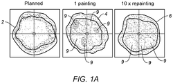
- Figure 1A illustrates three dose distributions with proton PBS to liver tumors.
- Dose distribution 2 shows a planned uniform dose distribution with proton PBS to a motionless liver tumor.
- Dose distribution 4 depicts delivered doses in simulated treatments without repainting (1 painting or spots painted once) with proton PBS to a moving liver tumor.
- dose distribution 6 depicts delivered doses in simulated treatments with 10 ⁇ repainting (spots painted 10 times) with proton PBS to a moving liver tumor.
- liver tumor motion and the scanning proton beam leads to severe underdoses/overdoses 9 in the dose distribution 4.
- This interplay effect is to some degree smeared out by the 10 repaintings in the dose distribution 6 to cause a reduction in underdoses/overdoses 9, but it is still a problem.
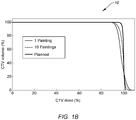
- Figure 1B depicts a dose-volume histogram 10 for the liver tumors of Figure 1A .
- the dose-volume histogram 10 points out the underdoses/overdoses 9 in the dose distributions 4 and 6.
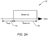
- Figure 2A shows a timing graph 12 of treatment delivery to a spot in a layer according to an embodiment.
- the spot has a waiting time t wait 14 (for layer shift or spot position shift) followed by a beam-on time t beam-on 16.
- Equation (1) of Figure 2B was derived from the patient treatment log files for the waiting time t wait 14.
- the threshold distance d threshold between spots is 10mm.
- the waiting time t wait 14 depends on the distance ( ⁇ x and ⁇ y) of the spot from the previous spot.
- the spot speeds v x and v y depend approximately linearly on the proton beam energy, but this is omitted in the modeling of the waiting time t wait 14. Although the modeling of the waiting time t wait 14 may be improved, it is found to be sufficiently accurate to demonstrate the advantages of the new scan technique to reduce the interplay effect.
- equation (2) of Figure 2B was derived from the patient treatment log files for the beam-on time t beam-on 16.
- the beam-on time t beam-on 16 of a spot is proportional to the dose or number of monitor units (MU) delivered to the spot.
- MU min_layer is the minimum number of MUs in any spot in the layer
- Figure 2B's equation (3) for t min represents approximate and empirically determined values for t min .
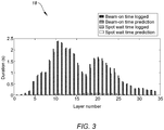
- Figure 3 depicts a comparison graph 18 of actual beam-on times t beam-on and beam waiting times t wait for 35 energy layers of a proton field with the beam-on times t beam-on and beam waiting times t wait as predicted from equations (1)-(3) according to an embodiment.
- the actual times are in agreement with the predicted times of equations (1)-(3), demonstrating the accuracy of equations (1)-(3).
- Figure 4 shows scatter plots 20 and 22 of actual and predicted values of t wait and t beam-on for all energy layers in 13 investigated clinical treatment fields according to an embodiment.
- equations (1)-(3) in general give a reasonably accurate prediction of beam-on time t beam-on and waiting time t wait .
- the root-mean-square error in the predicted times are 0.20s and 0.0026s for predicted beam-on time t beam-on and waiting time t wait , respectively.
- the new scan technique provides the ability to adjust the treatment delivery time of each energy layer to a period of movement (e.g., the breathing period of a patient).
- a period of movement e.g., the breathing period of a patient.
- the period of movement is assumed to be a breathing cycle of 4 seconds. It should be understood that the discussion is equally applicable to different types of periodic movement and different values for the period.
- FIG. 5 depicts a graph 24 of maximum and planned waiting times t wait and beam-on times t beam-on (or irradiation time) of spots in a layer according to an embodiment.
- the graph 24 shows time values for 35 energy layers. Maximum waiting times t wait may be obtained by maximizing the waiting time between spots of the layer while maximum beam-on times t beam-on may be obtained by decreasing beam current to its minimum.
- spots of a layer are sorted according to how many times the spots may be repainted. Specifically, the spots are sorted into repainting blocks (or groups) 30, 32, 34, 36, and 38 as illustrated in Figure 6 according to an embodiment. Depending on the number of MUs to be delivered of the spots, the layer's spots are sorted into repainting blocks 32, 34, 36, and 38 for the spots to be painted 2, 4, 8, and 16 times, respectively.
- Spots with ⁇ 2MU min are put into one of the 1-paint repainting blocks 30.
- the two 2-paint repainting blocks 32 are identical. They include the same sequence of spots and MUs.
- the four 4-paint repainting blocks 34 are identical while the eight 8-paint repainting blocks 36 are identical.
- the sixteen 16-paint repainting blocks 38 are identical. Spots with ⁇ 2MU min monitor units may not be repainted. They are divided into 1-paint repainting blocks 30, where odd numbered or designated spots are sorted into block 1a and even numbered or designated spots are sorted into block 1b.
- Figure 7 shows a table 40 with eight scan modes in order of increasingly slower scan duration according to an embodiment.
- Each scan mode has a different scan path strategy.
- the scan duration increases with the number of the scan mode because the overall waiting time t wait of the layer increases.
- scan modes Figure 7
- the repainting blocks (or groups) 30, 32, 34, 36, and 38 are rearranged as illustrated in Figure 9 according to an embodiment.
- the spots that may be painted once are divided into the repainting blocks 30, where block 1a includes odd spots and block 1b includes even spots.
- the spots in these repainting blocks 30 (e.g., the n'th spot in block 1a and the n'th spot in block 1b) will often be neighboring spots.
- the new scan technique with the quasi-periodic repainting scheme shown in Figure 9 ensures that these neighboring spots are visited with 2 seconds in between, which will tend to locally smear out the interplay effect even for these low-MU spots that may be painted once but not repainted.
- the 2-paint repainting blocks 32 are divided into four quarters (2.1, 2.2, 2,3, 2.4) that are visited with 2 seconds in between.
- the 4-paint repainting blocks 34 are divided into two halves (4.1, 4.2) that are visited with 1 second in between.
- the 1-paint repainting blocks 30 are divided into quarters (1.a1, 1.a2, 1.a3, 1.a4, 1.b1, 1.b2, 1.b3, 1.b4), where neighboring odd and even spots are visited with 2 seconds in between.
- the new scan technique with the repainting scheme shown in Figure 10 is used as an alternative according to an embodiment.
- the scan modes 8a and 8b allow any number of repaintings (both even and odd numbers).
- the two multi-paint repainting blocks 42 are identical and may include any number of paintings for a spot.
- the 1-paint repainting blocks 44 and 46 (1a and 1b) may include spots that are painted once as well as spots that are painted an odd number of times (n>3) and therefore also are placed in the multi-paint repainting blocks 42.
- the new scan technique with the quasi-periodic repainting scheme similar to Figure 9 may be obtained for each of the two breathing cycles.
- the spot scan pattern may be reversed for the first breathing cycle relative to the second breathing cycle in order to further smear out any residual interplay effect.
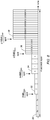
- FIG. 11 shows a graph 50 with examples of the treatment delivery durations of layers for one field with a planned treatment delivery without use of the new scan technique
- Figure 12 illustrates a graph 52 with examples of the treatment delivery durations of layers for one field with treatment delivery according Figures 9 (method 1) and 10 (method 2) according to an embodiment, where the times are calculated with equations (1)-(3) of Figure 2B .
- the graph 54 demonstrates that the actual treatment delivery times recorded in log files for 35 layers under the new scan technique are reasonably close to the predicted treatment delivery times with equations (1)-(3) of Figure 2B according to an embodiment.
- the treatment plans of five patients treated with proton PBS for thoracic and abdominal tumors were used for experimental dosimetric evaluation of the new scan technique.
- the five plans were two- or three-field plans with single-field-optimization in the treatment planning system and fraction doses between 1.8Gy and 4.5Gy.
- the tumors were pancreas, liver, lung/bronchus neoplasm, a non-small cell lung cancer tumor in right lower lobe, and a renal cell carcinoma.
- the plans represent a wide range of tumor sites, volumes, and doses.
- the five evaluation proton PBS plans had a total of 12 fields with 237 energy layers. The last two columns in Figure 7 show the percentage of layers and MUs for each of the eight scan modes.
- Each of the 12 proton PBS fields were delivered to an ion chamber array 62 carried by a motion stage 64.
- the ion chamber array 62 measured the 2D dose distribution with a frame rate of 0.1s. Blocks of solid water 66 on the ion chamber array 62 gave a measuring depth corresponding to a proximal end of the spread-out Bragg peak.
- Each field was delivered three times to the ion chamber array 62: Once without motion and twice with a 4s period, 3cm peak-to-peak, sinusoidal motion, where the treatment delivery was started at two different times relative to the motion cycle.
- the time resolved dose frames were summed in order to obtain the accumulated motion dose with the interplay effect as demonstrated in the upper row 72 of the block diagram 78 of Figure 15 .
- This dose was then compared with a reference dose, which was the accumulated static dose smeared or convolved with the known sinusoidal phantom motion as demonstrated in the lower row 74 of the block diagram 78 of Figure 15 .
- This reference dose represents an ideal motion dose distribution that is blurred due to motion, but otherwise without any interplay effect.
- the comparison with this reference dose was performed as a gamma test, where the percentage of ion chamber measurements fulfilling the 3%/3mm gamma pass criterion was reported. Ion chamber measurements with less than 10% of the maximum dose in the reference dose map were excluded in the gamma test.
- Figure 16 depicts examples of measured doses with an ion chamber array for a patient under treatment according to an embodiment. Illustrated are a static dose (measured) 80, a static dose (blurred) 82 convolved with the applied 3cm peak-to-peak sinusoidal motion, i.e. the ideal smearedout interplay-effect-free dose distribution.
- the three right columns show measured motion doses with the default delivery (no repainting) 84 and 85, conventional 8-repainting delivery 86 and 87, and treatment delivery according to the new scan technique 88 and 89 in experiments with the treatment starting in cranial phantom position (upper row) and caudal phantom position (lower row).
- the listed numbers specify the 3%/3mm gamma pass rate of the motion doses when compared with the ideal blurred static dose (i.e., compared with the static dose (blurred) 82).
- the treatment delivery according to the new scan technique 88 and 89 had (1) considerably higher gamma pass rates (i.e., lower interplay effect) and (2) considerably less variations when comparing one motion experiment with another.
- the time resolved 2D dose frames of the corresponding static experiment were first resampled to obtain the same number of dose frames for each energy layer as in the motion experiment as depicted in the block diagram 92 of Figure 18 according to an embodiment.
- the shift of each frame in the motion experiment i.e., the position of the motion stage at the moment of frame exposure
- the shifts of all motion frames were fitted to the known 3cm, 4s period sinusoidal motion. As result of this procedure, the phantom position for all dose frames in the motion experiment was now known.
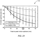
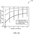
- the mean and standard deviation of the 3%/3mm gamma pass rate were calculated for all 10 N possible combinations of N-fraction treatment courses for each motion experiment.
- the results are shown in Figure 23 .
- the new scan technique (optimized) was clearly superior with a mean gamma pass rate after a single fraction (92.5%) that was equal to the mean gamma pass rate of 8 repaintings after 3.5 fractions, but with a much smaller standard deviation (error bars in Figure 23 ).
- the standard deviation was 4.6% after only 1 fraction delivered with the new scan technique (optimized) while it was still 5.7% after 6 fractions with 8 repaintings. It indicates the absence of outliers with large interplay effects for the new scan technique (optimized).
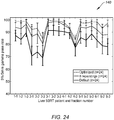
- the interplay effect was investigated for the actually measured tumor motion as measured for six liver SBRT patients during treatment delivery with kilovoltage intrafraction imaging (KIM) as shown in the graph 140 of Figure 24 according to an embodiment.
- KIM kilovoltage intrafraction imaging
- the results are shown in Figure 24 for the measured motion at all fractions (6 patients x 3 fractions/patient).
- the patient-measured motion trajectories have many irregularities such as variations in waveform, period, and amplitude from cycle to cycle as well as baseline shifts.
- the new scan technique (optimized) was superior to 8 repaintings (and no repaintings) for all fractions, the gamma pass rate was somewhat low for Patients 2 and 4, who had very fast breathing periods of less than 3 seconds.
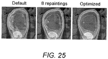
- Figure 26 depicts a dose-volume histogram 150 for the internal clinical target volume (ICTV) of 4D dose reconstruction in a treatment planning system with the default delivery, with 8 repaintings, and with the new scan technique (optimized) for the first patient (pancreas) according to an embodiment.
- the new scan technique (optimized) leads to a more uniform target dose with fewer interplay effects.
- the new scan technique may be implemented in many ways, notably as software running on a PC or similar.
- the presently disclosure further relates to a system for mitigating interplay effects in particle radiation therapy comprising a non-transitive, computer-readable storage device for storing instructions that performs a method for mitigating interplay effects in particle radiation therapy.
- the disclosure further relates to a computer program having instructions which when executed by a computing device or system causes the computing device or system to mitigate interplay effects in particle radiation therapy.
- Computer program should be construed broadly and include programs to be run on a PC, a part of the computer system facilities in a particle radiation therapy center, or software designed to run on smartphones, tablet computers or other mobile devices.
- Computer programs and mobile applications include software that is free and software that has to be bought, and also include software that is distributed over distribution software platforms.
- the present disclosure further relates to a particle therapy system comprising a particle beam generator for creating a particle beam used for particle radiation therapy, a beam transfer unit for delivering the particle radiation therapy to a target, a beam scanning unit configured to scan the particle beam across the target, and a processing unit configured to generate a scan pattern for the beam scanning unit by means described above to mitigate interplay effect of the particle radiation therapy.
- the particle therapy system may for example be a part of a proton center with one or more cyclotron accelerators.
- the present disclosure relates to a method for treatment of a cancer tumor in a region of a patient under periodic movement by submitting a target volume of the tumor to particle radiation therapy. In still another embodiment, the period of movement of the cancer tumor is obtained.
- the target volume is divided into a plurality of layers. Each of the layers is divided into a plurality of spots. A planned dose of particle radiation therapy of each spot of the target volume is calculated. A scan pattern is generated by means of the herein disclosed.
- the particle radiation therapy is delivered to the target volume (e.g., a tumor) according to the scan pattern to mitigate interplay effect of the particle radiation therapy.
- the cancer tumor (or several of them) may for example be located in the abdominal or the thoracic regions of the patient. But, cancer tumors in other anatomical regions may also be relevant, in particular if they are under influence of periodic movements during the particle radiation therapy.
Landscapes
- Health & Medical Sciences (AREA)
- Engineering & Computer Science (AREA)
- Biomedical Technology (AREA)
- Life Sciences & Earth Sciences (AREA)
- Pathology (AREA)
- Radiology & Medical Imaging (AREA)
- Nuclear Medicine, Radiotherapy & Molecular Imaging (AREA)
- Animal Behavior & Ethology (AREA)
- General Health & Medical Sciences (AREA)
- Public Health (AREA)
- Veterinary Medicine (AREA)
- Biophysics (AREA)
- Physiology (AREA)
- Radiation-Therapy Devices (AREA)
Claims (15)
- System, welches dazu konfiguriert ist, einen Strahlentherapieplan durch ein Durchführen eines Verfahrens zum Abschwächen einer Wechselwirkung bei einer Partikelstrahlentherapie zum Liefern an ein sich bewegendes Ziel zu erzeugen, welches einen Bewegungszeitraum beinhaltet, wobei die Partikelstrahlentherapie eine geplante Dosis an jedem Punkt jeder Schicht des sich bewegenden Ziels definiert, wobei das Verfahren Folgendes umfasst:Teilen der geplanten Dosis an jedem Punkt in eine Anzahl von punktuellen Repaintings; undErzeugen eines Abtastmusters für jede Schicht durch ein Definieren einer Strahl-an-Zeit (16) an jedem Punkt für jedes punktuelle Repainting, undBerechnen einer Wartezeit (14) zwischen konsekutiven Strahl-an-Zeiten, um die punktuellen Repaintings für jeden Punkt einer entsprechenden Schicht über eine Dauer einer ganzzahligen Anzahl von Bewegungszeiträumen zu verteilen.
- System nach Anspruch 1, welches dazu konfiguriert ist, dass die Anzahl von punktuellen Repaintings an jedem Punkt gemäß einer vorbestimmten Mindestdosis pro Punkt der Partikelstrahlentherapie maximiert ist.
- System nach Anspruch 1, welches dazu konfiguriert ist, dass die punktuellen Repaintings jedes Punkts einer Schicht gleichmäßig über die Dauer einer ganzzahligen Anzahl von Bewegungszeiträumen verteilt sind.
- System nach Anspruch 1, welches dazu konfiguriert ist, dass die Anzahl von punktuellen Repaintings für jeden Punkt in Blöcke (30, 32, 34, 36, 38) sortiert ist, wobei die Anzahl von punktuellen Repaintings in jedem Block (30, 32, 34, 36, 38) eine ganzzahlige Zweierpotenz ist.
- System nach Anspruch 4, welches dazu konfiguriert ist, dass die punktuellen Repaintings jedes Blocks (30, 32, 34, 36, 38) gleichmäßig über eine ganzzahlige Anzahl von Bewegungszeiträumen verteilt sind.
- System nach Anspruch 1, welches dazu konfiguriert ist, dass die punktuellen Repaintings in dem Abtastmuster verteilt sind durch ein Anpassen einer Sequenzreihenfolge von Punkten und/oder punktuellen Repaintings in einer Schicht und/oder der Wartezeit (14) zwischen konsekutiven Strahl-an-Zeiten (16) in einer Schicht.
- System nach Anspruch 1, welches dazu konfiguriert ist, dass die Wartezeit (14) zwischen konsekutiven Strahl-an-Zeiten (16) in einer Schicht angepasst ist durch ein Auswählen einer Strahlenpause vor einem oder mehreren Punkten in dem Abtastmuster.
- System nach Anspruch 1, wobei Partikel für die Partikelbestrahlungstherapie aus der Gruppe von Folgendem sind:Protonen, Ionen, Neutronen und Elektronen;
und/oderwobei das System dazu konfiguriert ist, dass die Partikelstrahlentherapie mithilfe eines Nadelstrahlabtastens ausgeführt wird. - System nach Anspruch 1, wobei der Bewegungszeitraum aufgrund von Atmung und/oder Herzschlag eines Patienten ist, welcher das sich bewegende Ziel umfasst,
und/oder
wobei die Atmungs- und/oder der Herzschlagbewegung eine Atmungs- und/oder einen Herzschlagzeitraum beinhaltet und mit vierdimensionaler Computertomografie bestimmt wird. - System nach Anspruch 1, welches ferner konfiguriert ist:zum Unterstützen einer Synchronisation einer Atmung eines Patienten und des Bewegungszeitraum;
und/oderdass der Patient durch Audio- und/oder Videoanweisung unterstützt wird. - System nach Anspruch 1, welches dazu konfiguriert ist, dass das Abtastmuster erzeugt wird, so dass punktuelle Repaintings von Punkten in einer Schicht, welche einmal bestrahlt werden, so verteilt werden, dass eine erste Gruppe (30, 1a) der Punkte während eines ersten Teils des Zeitraums der periodischen Bewegung bestrahlt wird und eine zweite Gruppe (30, 1b) der Punkte während eines zweiten Teils des Bewegungszeitraums bestrahlt wird.
- System nach Anspruch 1, welches dazu konfiguriert ist, dass das Abtastmuster erzeugt wird, so dass Schichten mit Abtastzeiten von zwei Zeiträumen abgetastet werden, so dass Erneuerungsanstrichblöcke (32) aus zwei oder mehr punktuellen Repaintings in zwei identische Abtastmuster getrennt werden, wobei ein erstes Abtastmuster in einem ersten Zeitraum aus zwei Zeiträumen durchgeführt wird und ein zweites Abtastmuster in einem zweiten Zeitraum aus zwei Zeiträumen durchgeführt wird.
- System nach Anspruch 1, welches dazu konfiguriert ist, dass das Abtastmuster erzeugt wird, so dass Schichten mit Abtastzeiten von zwei Zeiträumen abgetastet werden, so dass Erneuerungsanstrichblöcke (32, 34, 36, 38) aus zwei oder mehr punktuellen Repaintings in zwei Abtastmuster getrennt werden, wobei ein erstes Abtastmuster in einem ersten Zeitraum durchgeführt wird und ein zweites Abtastmuster in einem zweiten Zeitraum durchgeführt wird, und wobei das zweite Abtastmuster umgekehrt zu dem ersten Abtastmuster ist.
- System nach Anspruch 1, welches dazu konfiguriert ist, dass das Abtastmuster erzeugt wird, so dass Schichten mit einer Abtastzeitdauer, welche geringer ist als der Bewegungszeitraum, unter Verwendung eines Musters mit einer maximalen Abtastzeitdauer abgetastet werden.
- Computerimplementiertes Verfahren zum Erzeugen eines Abtastmusters zur Behandlung eines Krebstumors in einem Bereich eines Patienten, welcher periodischen Bewegungen unterliegt, indem ein Zielvolumen des Tumors einer Partikelstrahlentherapie unterzogen wird, wobei das Verfahren Folgendes umfasst:Erlangen eines Bewegungszeitraums des Krebstumors;Teilen des Zielvolumens in eine Vielzahl von Schichten und Teilen jeder der Schichten in eine Vielzahl von Punkten;Berechnen einer geplanten Dosis der Partikelstrahlentherapie jedes Punkts des Zielvolumens und Teilen der geplanten Dosis in jedem Punkt jeder Schicht in eine Anzahl von punktuellen Repaintings; undErzeugen eines Abtastmusters für jede Schicht durch ein Definieren einer Strahl-an-Zeit (16) an jedem Punkt für jedes punktuelle Repainting und Berechnen einer Wartezeit (14) zwischen konsekutiven Strahl-an-Zeiten, um die punktuellen Repaintings für jeden Punkt einer entsprechenden Schicht über eine Dauer einer ganzzahligen Anzahl von Bewegungszeiträumen zu verteilen.
Applications Claiming Priority (2)
| Application Number | Priority Date | Filing Date | Title |
|---|---|---|---|
| US201762445008P | 2017-01-11 | 2017-01-11 | |
| PCT/US2018/021475 WO2018132847A1 (en) | 2017-01-11 | 2018-03-08 | Mitigation of interplay effect in particle radiation therapy |
Publications (3)
| Publication Number | Publication Date |
|---|---|
| EP3568199A1 EP3568199A1 (de) | 2019-11-20 |
| EP3568199A4 EP3568199A4 (de) | 2020-08-05 |
| EP3568199B1 true EP3568199B1 (de) | 2021-12-01 |
Family
ID=62840272
Family Applications (1)
| Application Number | Title | Priority Date | Filing Date |
|---|---|---|---|
| EP18738677.6A Active EP3568199B1 (de) | 2017-01-11 | 2018-03-08 | Abschwächung des zusammenwirkeffektes bei der teilchenstrahlentherapie |
Country Status (4)
| Country | Link |
|---|---|
| US (1) | US10583313B2 (de) |
| EP (1) | EP3568199B1 (de) |
| CN (1) | CN110662579B (de) |
| WO (1) | WO2018132847A1 (de) |
Families Citing this family (6)
| Publication number | Priority date | Publication date | Assignee | Title |
|---|---|---|---|---|
| US11623107B2 (en) * | 2016-10-20 | 2023-04-11 | William Beaumont Hospital | Particle arc therapy |
| JP7433927B2 (ja) * | 2020-01-22 | 2024-02-20 | キヤノンメディカルシステムズ株式会社 | 放射線治療計画装置 |
| EP4115948B1 (de) * | 2021-07-09 | 2023-11-29 | Ion Beam Applications | Behandlungsvorrichtung zum ausgeben eines behandlungsplans für die blitzabscheidung mit einem beschleuniger für geladene teilchen durch stiftstrahlabtastung |
| CN114146329B (zh) * | 2021-12-07 | 2023-06-23 | 江苏省中医院 | 一种引入伽玛通过率优化目标的放射治疗计划优化系统 |
| US12076587B2 (en) * | 2022-03-29 | 2024-09-03 | Siemens Healthineers International Ag | Dose smearing effect modeling for radiation treatment plan |
| CN117653937B (zh) * | 2024-01-31 | 2024-04-19 | 四川大学华西医院 | 一种分离放疗中剂量学效应的方法、系统和存储介质 |
Family Cites Families (15)
| Publication number | Priority date | Publication date | Assignee | Title |
|---|---|---|---|---|
| DE102005063220A1 (de) * | 2005-12-22 | 2007-06-28 | GSI Gesellschaft für Schwerionenforschung mbH | Vorrichtung zum Bestrahlen von Tumorgewebe eines Patienten mit einem Teilchenstrahl |
| US20100059688A1 (en) * | 2006-07-06 | 2010-03-11 | Ion Beam Applications S.A. | Method And Software For Irradiating A Target Volume With A Particle Beam And Device Implementing Same |
| EP2189185B1 (de) * | 2007-09-12 | 2014-04-30 | Kabushiki Kaisha Toshiba | Partikelstrahlprojektionsvorrichtung |
| WO2009142549A2 (en) * | 2008-05-22 | 2009-11-26 | Vladimir Yegorovich Balakin | Multi-axis charged particle cancer therapy method and apparatus |
| JP5463509B2 (ja) * | 2010-02-10 | 2014-04-09 | 株式会社東芝 | 粒子線ビーム照射装置及びその制御方法 |
| WO2012117538A1 (ja) * | 2011-03-02 | 2012-09-07 | 三菱電機株式会社 | 粒子線照射システムおよび粒子線照射システムの制御方法 |
| JP5816518B2 (ja) * | 2011-10-31 | 2015-11-18 | 株式会社日立製作所 | 粒子線照射システム及びビーム補正方法 |
| US20130303899A1 (en) | 2012-05-14 | 2013-11-14 | University Of Maryland, Baltimore | Quantitative evaluation of fractional regional ventilation using four-dimensional computed tomography |
| US9393443B2 (en) * | 2012-07-30 | 2016-07-19 | Hitachi, Ltd. | Treatment planning system |
| DE102012112348B4 (de) * | 2012-12-14 | 2014-11-06 | Gsi Helmholtzzentrum Für Schwerionenforschung Gmbh | Bestrahlungsplanung einer Partikelbestrahlung unter Berücksichtigung einer Bewegung eines Zielvolumens |
| JP6150650B2 (ja) * | 2013-07-26 | 2017-06-21 | 株式会社日立製作所 | 粒子線照射システムとその運転方法 |
| US20160030769A1 (en) * | 2014-08-01 | 2016-02-04 | Phenix Medical Llc | Method and device for fast raster beam scanning in intensity-modulated ion beam therapy |
| US10786689B2 (en) * | 2015-11-10 | 2020-09-29 | Mevion Medical Systems, Inc. | Adaptive aperture |
| EP3195901A1 (de) * | 2016-01-20 | 2017-07-26 | Ion Beam Applications S.A. | Verfahren und vorrichtung zur bestimmung eines interesses der anwendung einer qa-prozedur für einen behandlungsplan bei strahlentherapie |
| WO2018009779A1 (en) * | 2016-07-08 | 2018-01-11 | Mevion Medical Systems, Inc. | Treatment planning |
-
2018
- 2018-02-28 US US15/908,334 patent/US10583313B2/en active Active
- 2018-03-08 WO PCT/US2018/021475 patent/WO2018132847A1/en not_active Ceased
- 2018-03-08 CN CN201880017364.7A patent/CN110662579B/zh active Active
- 2018-03-08 EP EP18738677.6A patent/EP3568199B1/de active Active
Also Published As
| Publication number | Publication date |
|---|---|
| US10583313B2 (en) | 2020-03-10 |
| CN110662579B (zh) | 2021-10-22 |
| EP3568199A4 (de) | 2020-08-05 |
| WO2018132847A1 (en) | 2018-07-19 |
| EP3568199A1 (de) | 2019-11-20 |
| US20180280729A1 (en) | 2018-10-04 |
| CN110662579A (zh) | 2020-01-07 |
Similar Documents
| Publication | Publication Date | Title |
|---|---|---|
| US10583313B2 (en) | Mitigation of interplay effect in particle radiation therapy | |
| EP2190531B1 (de) | Gerät zur bestrahlung eines beweglichen zielvolumens | |
| Li et al. | Reducing dose uncertainty for spot-scanning proton beam therapy of moving tumors by optimizing the spot delivery sequence | |
| Rao et al. | Dosimetric impact of breathing motion in lung stereotactic body radiotherapy treatment using image-modulated radiotherapy and volumetric modulated arc therapy | |
| US9855445B2 (en) | Radiation therapy systems and methods for delivering doses to a target volume | |
| Zhang et al. | A statistical comparison of motion mitigation performances and robustness of various pencil beam scanned proton systems for liver tumour treatments | |
| Victoria et al. | A prospective 4π radiation therapy clinical study in recurrent high-grade glioma patients | |
| CN102725029B (zh) | 用于在辐照期间控制剂量施用的方法和装置 | |
| Poulsen et al. | Efficient interplay effect mitigation for proton pencil beam scanning by spot-adapted layered repainting evenly spread out over the full breathing cycle | |
| Zhang et al. | Online image guided tumour tracking with scanned proton beams: a comprehensive simulation study | |
| EP3297725B1 (de) | System zur schichtinternen synchronisation für schnelle punktneuabtastung | |
| CN104902957B (zh) | 用于计划照射的方法 | |
| Furukawa et al. | Development of NIRS pencil beam scanning system for carbon ion radiotherapy | |
| US10342995B2 (en) | System and method for scanned ion beam interplay effect mitigation using random repainting | |
| Knopf et al. | In the context of radiosurgery–pros and cons of rescanning as a solution for treating moving targets with scanned particle beams | |
| Leste et al. | A study of the interplay effect in radiation therapy using a Monte-Carlo model | |
| Grelewicz et al. | Combined MV+ kV inverse treatment planning for optimal kV dose incorporation in IGRT | |
| Chen et al. | Real-time gated proton therapy: commissioning and clinical workflow for the Hitachi System | |
| Gorgisyan et al. | The dosimetric effect of residual breath-hold motion in pencil beam scanned proton therapy–an experimental study | |
| Tsunashima | Verification of the clinical implementation of the respiratory gated beam delivery technique with synchrotron-based proton irradiation | |
| Deisher et al. | Radiation Physics: Charged Particle Therapy | |
| He et al. | Target motion compensation by means of adjustable heavy-ion beam slow extraction: simulations | |
| Lüchtenborg | Real-time dose compensation methods for scanned ion beam therapy of moving tumors | |
| Pella | Technologies and methods for treatment geometry optimization in radiation therapy with accelerated particles | |
| Alidzulwi et al. | O7. Implementation of an Intensity-Modulated Radiation Therapy (IMRT) and Volumetric-Modulated Arc Therapy (VMAT) quality control program using a portal dosimetry system |
Legal Events
| Date | Code | Title | Description |
|---|---|---|---|
| STAA | Information on the status of an ep patent application or granted ep patent |
Free format text: STATUS: THE INTERNATIONAL PUBLICATION HAS BEEN MADE |
|
| PUAI | Public reference made under article 153(3) epc to a published international application that has entered the european phase |
Free format text: ORIGINAL CODE: 0009012 |
|
| STAA | Information on the status of an ep patent application or granted ep patent |
Free format text: STATUS: REQUEST FOR EXAMINATION WAS MADE |
|
| 17P | Request for examination filed |
Effective date: 20190809 |
|
| AK | Designated contracting states |
Kind code of ref document: A1 Designated state(s): AL AT BE BG CH CY CZ DE DK EE ES FI FR GB GR HR HU IE IS IT LI LT LU LV MC MK MT NL NO PL PT RO RS SE SI SK SM TR |
|
| AX | Request for extension of the european patent |
Extension state: BA ME |
|
| RAP1 | Party data changed (applicant data changed or rights of an application transferred) |
Owner name: UNIVERSITY OF MARYLAND, BALTIMORE Owner name: VARIAN MEDICAL SYSTEMS PARTICLE THERAPY GMBH |
|
| DAV | Request for validation of the european patent (deleted) | ||
| A4 | Supplementary search report drawn up and despatched |
Effective date: 20200702 |
|
| RIC1 | Information provided on ipc code assigned before grant |
Ipc: A61N 5/10 20060101ALI20200626BHEP Ipc: A61N 5/00 20060101AFI20200626BHEP |
|
| RAP3 | Party data changed (applicant data changed or rights of an application transferred) |
Owner name: VARIAN MEDICAL SYSTEMS PARTICLE THERAPY GMBH & CO. KG Owner name: UNIVERSITY OF MARYLAND, BALTIMORE |
|
| GRAP | Despatch of communication of intention to grant a patent |
Free format text: ORIGINAL CODE: EPIDOSNIGR1 |
|
| STAA | Information on the status of an ep patent application or granted ep patent |
Free format text: STATUS: GRANT OF PATENT IS INTENDED |
|
| INTG | Intention to grant announced |
Effective date: 20210629 |
|
| GRAS | Grant fee paid |
Free format text: ORIGINAL CODE: EPIDOSNIGR3 |
|
| GRAA | (expected) grant |
Free format text: ORIGINAL CODE: 0009210 |
|
| STAA | Information on the status of an ep patent application or granted ep patent |
Free format text: STATUS: THE PATENT HAS BEEN GRANTED |
|
| AK | Designated contracting states |
Kind code of ref document: B1 Designated state(s): AL AT BE BG CH CY CZ DE DK EE ES FI FR GB GR HR HU IE IS IT LI LT LU LV MC MK MT NL NO PL PT RO RS SE SI SK SM TR |
|
| REG | Reference to a national code |
Ref country code: GB Ref legal event code: FG4D |
|
| REG | Reference to a national code |
Ref country code: AT Ref legal event code: REF Ref document number: 1451197 Country of ref document: AT Kind code of ref document: T Effective date: 20211215 Ref country code: CH Ref legal event code: EP |
|
| REG | Reference to a national code |
Ref country code: IE Ref legal event code: FG4D |
|
| REG | Reference to a national code |
Ref country code: DE Ref legal event code: R096 Ref document number: 602018027506 Country of ref document: DE |
|
| REG | Reference to a national code |
Ref country code: LT Ref legal event code: MG9D |
|
| REG | Reference to a national code |
Ref country code: NL Ref legal event code: MP Effective date: 20211201 |
|
| REG | Reference to a national code |
Ref country code: AT Ref legal event code: MK05 Ref document number: 1451197 Country of ref document: AT Kind code of ref document: T Effective date: 20211201 |
|
| PG25 | Lapsed in a contracting state [announced via postgrant information from national office to epo] |
Ref country code: RS Free format text: LAPSE BECAUSE OF FAILURE TO SUBMIT A TRANSLATION OF THE DESCRIPTION OR TO PAY THE FEE WITHIN THE PRESCRIBED TIME-LIMIT Effective date: 20211201 Ref country code: LT Free format text: LAPSE BECAUSE OF FAILURE TO SUBMIT A TRANSLATION OF THE DESCRIPTION OR TO PAY THE FEE WITHIN THE PRESCRIBED TIME-LIMIT Effective date: 20211201 Ref country code: FI Free format text: LAPSE BECAUSE OF FAILURE TO SUBMIT A TRANSLATION OF THE DESCRIPTION OR TO PAY THE FEE WITHIN THE PRESCRIBED TIME-LIMIT Effective date: 20211201 Ref country code: BG Free format text: LAPSE BECAUSE OF FAILURE TO SUBMIT A TRANSLATION OF THE DESCRIPTION OR TO PAY THE FEE WITHIN THE PRESCRIBED TIME-LIMIT Effective date: 20220301 Ref country code: AT Free format text: LAPSE BECAUSE OF FAILURE TO SUBMIT A TRANSLATION OF THE DESCRIPTION OR TO PAY THE FEE WITHIN THE PRESCRIBED TIME-LIMIT Effective date: 20211201 |
|
| PG25 | Lapsed in a contracting state [announced via postgrant information from national office to epo] |
Ref country code: SE Free format text: LAPSE BECAUSE OF FAILURE TO SUBMIT A TRANSLATION OF THE DESCRIPTION OR TO PAY THE FEE WITHIN THE PRESCRIBED TIME-LIMIT Effective date: 20211201 Ref country code: PL Free format text: LAPSE BECAUSE OF FAILURE TO SUBMIT A TRANSLATION OF THE DESCRIPTION OR TO PAY THE FEE WITHIN THE PRESCRIBED TIME-LIMIT Effective date: 20211201 Ref country code: NO Free format text: LAPSE BECAUSE OF FAILURE TO SUBMIT A TRANSLATION OF THE DESCRIPTION OR TO PAY THE FEE WITHIN THE PRESCRIBED TIME-LIMIT Effective date: 20220301 Ref country code: LV Free format text: LAPSE BECAUSE OF FAILURE TO SUBMIT A TRANSLATION OF THE DESCRIPTION OR TO PAY THE FEE WITHIN THE PRESCRIBED TIME-LIMIT Effective date: 20211201 Ref country code: HR Free format text: LAPSE BECAUSE OF FAILURE TO SUBMIT A TRANSLATION OF THE DESCRIPTION OR TO PAY THE FEE WITHIN THE PRESCRIBED TIME-LIMIT Effective date: 20211201 Ref country code: GR Free format text: LAPSE BECAUSE OF FAILURE TO SUBMIT A TRANSLATION OF THE DESCRIPTION OR TO PAY THE FEE WITHIN THE PRESCRIBED TIME-LIMIT Effective date: 20220302 Ref country code: ES Free format text: LAPSE BECAUSE OF FAILURE TO SUBMIT A TRANSLATION OF THE DESCRIPTION OR TO PAY THE FEE WITHIN THE PRESCRIBED TIME-LIMIT Effective date: 20211201 |
|
| PG25 | Lapsed in a contracting state [announced via postgrant information from national office to epo] |
Ref country code: NL Free format text: LAPSE BECAUSE OF FAILURE TO SUBMIT A TRANSLATION OF THE DESCRIPTION OR TO PAY THE FEE WITHIN THE PRESCRIBED TIME-LIMIT Effective date: 20211201 |
|
| PG25 | Lapsed in a contracting state [announced via postgrant information from national office to epo] |
Ref country code: SM Free format text: LAPSE BECAUSE OF FAILURE TO SUBMIT A TRANSLATION OF THE DESCRIPTION OR TO PAY THE FEE WITHIN THE PRESCRIBED TIME-LIMIT Effective date: 20211201 Ref country code: SK Free format text: LAPSE BECAUSE OF FAILURE TO SUBMIT A TRANSLATION OF THE DESCRIPTION OR TO PAY THE FEE WITHIN THE PRESCRIBED TIME-LIMIT Effective date: 20211201 Ref country code: RO Free format text: LAPSE BECAUSE OF FAILURE TO SUBMIT A TRANSLATION OF THE DESCRIPTION OR TO PAY THE FEE WITHIN THE PRESCRIBED TIME-LIMIT Effective date: 20211201 Ref country code: PT Free format text: LAPSE BECAUSE OF FAILURE TO SUBMIT A TRANSLATION OF THE DESCRIPTION OR TO PAY THE FEE WITHIN THE PRESCRIBED TIME-LIMIT Effective date: 20220401 Ref country code: EE Free format text: LAPSE BECAUSE OF FAILURE TO SUBMIT A TRANSLATION OF THE DESCRIPTION OR TO PAY THE FEE WITHIN THE PRESCRIBED TIME-LIMIT Effective date: 20211201 Ref country code: CZ Free format text: LAPSE BECAUSE OF FAILURE TO SUBMIT A TRANSLATION OF THE DESCRIPTION OR TO PAY THE FEE WITHIN THE PRESCRIBED TIME-LIMIT Effective date: 20211201 |
|
| REG | Reference to a national code |
Ref country code: DE Ref legal event code: R097 Ref document number: 602018027506 Country of ref document: DE |
|
| PG25 | Lapsed in a contracting state [announced via postgrant information from national office to epo] |
Ref country code: IS Free format text: LAPSE BECAUSE OF FAILURE TO SUBMIT A TRANSLATION OF THE DESCRIPTION OR TO PAY THE FEE WITHIN THE PRESCRIBED TIME-LIMIT Effective date: 20220401 |
|
| PLBE | No opposition filed within time limit |
Free format text: ORIGINAL CODE: 0009261 |
|
| STAA | Information on the status of an ep patent application or granted ep patent |
Free format text: STATUS: NO OPPOSITION FILED WITHIN TIME LIMIT |
|
| PG25 | Lapsed in a contracting state [announced via postgrant information from national office to epo] |
Ref country code: MC Free format text: LAPSE BECAUSE OF FAILURE TO SUBMIT A TRANSLATION OF THE DESCRIPTION OR TO PAY THE FEE WITHIN THE PRESCRIBED TIME-LIMIT Effective date: 20211201 Ref country code: DK Free format text: LAPSE BECAUSE OF FAILURE TO SUBMIT A TRANSLATION OF THE DESCRIPTION OR TO PAY THE FEE WITHIN THE PRESCRIBED TIME-LIMIT Effective date: 20211201 Ref country code: AL Free format text: LAPSE BECAUSE OF FAILURE TO SUBMIT A TRANSLATION OF THE DESCRIPTION OR TO PAY THE FEE WITHIN THE PRESCRIBED TIME-LIMIT Effective date: 20211201 |
|
| REG | Reference to a national code |
Ref country code: CH Ref legal event code: PL |
|
| 26N | No opposition filed |
Effective date: 20220902 |
|
| PG25 | Lapsed in a contracting state [announced via postgrant information from national office to epo] |
Ref country code: SI Free format text: LAPSE BECAUSE OF FAILURE TO SUBMIT A TRANSLATION OF THE DESCRIPTION OR TO PAY THE FEE WITHIN THE PRESCRIBED TIME-LIMIT Effective date: 20211201 |
|
| REG | Reference to a national code |
Ref country code: BE Ref legal event code: MM Effective date: 20220331 |
|
| PG25 | Lapsed in a contracting state [announced via postgrant information from national office to epo] |
Ref country code: LU Free format text: LAPSE BECAUSE OF NON-PAYMENT OF DUE FEES Effective date: 20220308 Ref country code: LI Free format text: LAPSE BECAUSE OF NON-PAYMENT OF DUE FEES Effective date: 20220331 Ref country code: IE Free format text: LAPSE BECAUSE OF NON-PAYMENT OF DUE FEES Effective date: 20220308 Ref country code: FR Free format text: LAPSE BECAUSE OF NON-PAYMENT OF DUE FEES Effective date: 20220331 Ref country code: CH Free format text: LAPSE BECAUSE OF NON-PAYMENT OF DUE FEES Effective date: 20220331 |
|
| PG25 | Lapsed in a contracting state [announced via postgrant information from national office to epo] |
Ref country code: BE Free format text: LAPSE BECAUSE OF NON-PAYMENT OF DUE FEES Effective date: 20220331 |
|
| PG25 | Lapsed in a contracting state [announced via postgrant information from national office to epo] |
Ref country code: IT Free format text: LAPSE BECAUSE OF FAILURE TO SUBMIT A TRANSLATION OF THE DESCRIPTION OR TO PAY THE FEE WITHIN THE PRESCRIBED TIME-LIMIT Effective date: 20211201 |
|
| PG25 | Lapsed in a contracting state [announced via postgrant information from national office to epo] |
Ref country code: MK Free format text: LAPSE BECAUSE OF FAILURE TO SUBMIT A TRANSLATION OF THE DESCRIPTION OR TO PAY THE FEE WITHIN THE PRESCRIBED TIME-LIMIT Effective date: 20211201 Ref country code: CY Free format text: LAPSE BECAUSE OF FAILURE TO SUBMIT A TRANSLATION OF THE DESCRIPTION OR TO PAY THE FEE WITHIN THE PRESCRIBED TIME-LIMIT Effective date: 20211201 |
|
| PG25 | Lapsed in a contracting state [announced via postgrant information from national office to epo] |
Ref country code: HU Free format text: LAPSE BECAUSE OF FAILURE TO SUBMIT A TRANSLATION OF THE DESCRIPTION OR TO PAY THE FEE WITHIN THE PRESCRIBED TIME-LIMIT; INVALID AB INITIO Effective date: 20180308 |
|
| PG25 | Lapsed in a contracting state [announced via postgrant information from national office to epo] |
Ref country code: MT Free format text: LAPSE BECAUSE OF FAILURE TO SUBMIT A TRANSLATION OF THE DESCRIPTION OR TO PAY THE FEE WITHIN THE PRESCRIBED TIME-LIMIT Effective date: 20211201 |
|
| PGFP | Annual fee paid to national office [announced via postgrant information from national office to epo] |
Ref country code: DE Payment date: 20250520 Year of fee payment: 8 |
|
| PGFP | Annual fee paid to national office [announced via postgrant information from national office to epo] |
Ref country code: GB Payment date: 20250403 Year of fee payment: 8 |
|
| PG25 | Lapsed in a contracting state [announced via postgrant information from national office to epo] |
Ref country code: TR Free format text: LAPSE BECAUSE OF FAILURE TO SUBMIT A TRANSLATION OF THE DESCRIPTION OR TO PAY THE FEE WITHIN THE PRESCRIBED TIME-LIMIT Effective date: 20211201 |