EP3568312B1 - Système de surveillance optique - Google Patents
Système de surveillance optique Download PDFInfo
- Publication number
- EP3568312B1 EP3568312B1 EP18709259.8A EP18709259A EP3568312B1 EP 3568312 B1 EP3568312 B1 EP 3568312B1 EP 18709259 A EP18709259 A EP 18709259A EP 3568312 B1 EP3568312 B1 EP 3568312B1
- Authority
- EP
- European Patent Office
- Prior art keywords
- module
- fbg
- conductor
- sensors
- sensor
- Prior art date
- Legal status (The legal status is an assumption and is not a legal conclusion. Google has not performed a legal analysis and makes no representation as to the accuracy of the status listed.)
- Active
Links
Images



Classifications
-
- B—PERFORMING OPERATIONS; TRANSPORTING
- B60—VEHICLES IN GENERAL
- B60L—PROPULSION OF ELECTRICALLY-PROPELLED VEHICLES; SUPPLYING ELECTRIC POWER FOR AUXILIARY EQUIPMENT OF ELECTRICALLY-PROPELLED VEHICLES; ELECTRODYNAMIC BRAKE SYSTEMS FOR VEHICLES IN GENERAL; MAGNETIC SUSPENSION OR LEVITATION FOR VEHICLES; MONITORING OPERATING VARIABLES OF ELECTRICALLY-PROPELLED VEHICLES; ELECTRIC SAFETY DEVICES FOR ELECTRICALLY-PROPELLED VEHICLES
- B60L5/00—Current collectors for power supply lines of electrically-propelled vehicles
- B60L5/18—Current collectors for power supply lines of electrically-propelled vehicles using bow-type collectors in contact with trolley wire
- B60L5/20—Details of contact bow
- B60L5/205—Details of contact bow with carbon contact members
-
- G—PHYSICS
- G01—MEASURING; TESTING
- G01L—MEASURING FORCE, STRESS, TORQUE, WORK, MECHANICAL POWER, MECHANICAL EFFICIENCY, OR FLUID PRESSURE
- G01L1/00—Measuring force or stress, in general
- G01L1/24—Measuring force or stress, in general by measuring variations of optical properties of material when it is stressed, e.g. by photoelastic stress analysis using infrared, visible light, ultraviolet
- G01L1/242—Measuring force or stress, in general by measuring variations of optical properties of material when it is stressed, e.g. by photoelastic stress analysis using infrared, visible light, ultraviolet the material being an optical fibre
- G01L1/246—Measuring force or stress, in general by measuring variations of optical properties of material when it is stressed, e.g. by photoelastic stress analysis using infrared, visible light, ultraviolet the material being an optical fibre using integrated gratings, e.g. Bragg gratings
-
- B—PERFORMING OPERATIONS; TRANSPORTING
- B60—VEHICLES IN GENERAL
- B60L—PROPULSION OF ELECTRICALLY-PROPELLED VEHICLES; SUPPLYING ELECTRIC POWER FOR AUXILIARY EQUIPMENT OF ELECTRICALLY-PROPELLED VEHICLES; ELECTRODYNAMIC BRAKE SYSTEMS FOR VEHICLES IN GENERAL; MAGNETIC SUSPENSION OR LEVITATION FOR VEHICLES; MONITORING OPERATING VARIABLES OF ELECTRICALLY-PROPELLED VEHICLES; ELECTRIC SAFETY DEVICES FOR ELECTRICALLY-PROPELLED VEHICLES
- B60L5/00—Current collectors for power supply lines of electrically-propelled vehicles
- B60L5/18—Current collectors for power supply lines of electrically-propelled vehicles using bow-type collectors in contact with trolley wire
- B60L5/22—Supporting means for the contact bow
- B60L5/24—Pantographs
-
- B—PERFORMING OPERATIONS; TRANSPORTING
- B60—VEHICLES IN GENERAL
- B60L—PROPULSION OF ELECTRICALLY-PROPELLED VEHICLES; SUPPLYING ELECTRIC POWER FOR AUXILIARY EQUIPMENT OF ELECTRICALLY-PROPELLED VEHICLES; ELECTRODYNAMIC BRAKE SYSTEMS FOR VEHICLES IN GENERAL; MAGNETIC SUSPENSION OR LEVITATION FOR VEHICLES; MONITORING OPERATING VARIABLES OF ELECTRICALLY-PROPELLED VEHICLES; ELECTRIC SAFETY DEVICES FOR ELECTRICALLY-PROPELLED VEHICLES
- B60L2200/00—Type of vehicles
- B60L2200/26—Rail vehicles
Definitions
- This invention relates to an optical monitoring system, in particular to a monitoring system that includes a plurality of optical sensor modules.
- the system disclosed may be utilised for monitoring a current collector, for example a collector of the type that is employed by an electric vehicle (such as a train or tram) to draw current from a conductor, for example an overhead conductor wire (known as a catenary) or a conducting rail.
- a current collector for example a collector of the type that is employed by an electric vehicle (such as a train or tram) to draw current from a conductor, for example an overhead conductor wire (known as a catenary) or a conducting rail.
- a current collector for example a collector of the type that is employed by an electric vehicle (such as a train or tram) to draw current from a conductor, for example an overhead conductor wire (known as a catenary) or a conducting rail.
- teachings of the present invention may be employed to monitor other types of current collectors, for example current collectors employed in electrical motors and the like.
- pantograph is a critical, roof-mounted part of a modern electric train, tram or bus that functions to collect current from an overhead catenary wire.
- Successful current collection requires a reliable pantograph-catenary contact with a steady force under all conditions, in particular against mechanical, dynamic and aerodynamic effects seen as the train travels along the line.
- the contact force at the interface of pantograph-catenary varies as a function of speed and is documented in industrial standards, for example British Standard BS EN 50367.
- the contact force must be steady to provide acceptable current-collecting efficiency. If the contact force is lower than that required, there is a power loss, for example, in the form of electric arcs. The high rate of arcing and continuous sparking can induce strong electromagnetic noise in the environment as well as electricity-induced wear. If the contact force is higher than that required, wear of the carbon blocks carried by the pantograph becomes an important issue due to the increased mechanical friction, thus resulting in a shortened lifetime of the pantograph.
- Camolli et al reported the use of two fibres (see: L. Comolli, G. Bucca, M. Bocciolone and A. Collina. 2008. First results from in-line strain measurements with FBG sensors on the pantograph collector of underground trains. Proceeding of SPIE. Vol. 7726 ), each carrying a single FBG only, for the pantograph contact force measurement, with one FBG being used for strain measurement and the other for temperature compensation.
- the FBG sensor for temperature compensation is mounted in an orthogonal direction to that for strain measurement and at a position where the strain values are the lowest. This approach is based on the assumption that the temperature distribution in the carbon collector block is uniform along the pan-head, but as this is not true in reality this approach will likely lead to inaccurate readings.
- Each pantograph pan head is provided with two aluminium boxes, and as each pantograph typically includes two pan heads there are therefore 12 FBG sensors that need to be connected to the interrogation equipment using 4 fibre patch leads.
- This complexity aside, the proposal is disadvantageous as the addition of 4 aluminium boxes to the pan-heads of the pantograph increases the mass of the pan-heads and hence the aerodynamic force when a train moves at a high speed.
- European Patent No. EP 1975584 discloses the use of two FBGs in a "push-pull" configuration with one being configured in a 'tensile' condition and the other in 'compression' when the contact force is applied. The acting force can thus be determined by cancelling out the temperature effect and doubling the strain measurement sensitivity. However, this is only valid when the two FBGs are subject to the same temperature effects, which is not necessarily true in reality.
- WO2014072436 A1 US6125216A and WO 2006107278 A1 reveal further monitoring systems for electric vehicles drawing current from a conductor by means of a current collector which employ fibre Bragg grating sensors (FBG sensors).
- FBG sensors fibre Bragg grating sensors
- US Patent No. 6125216 discloses another strain-isolated FBG sensor that can be used, in common with the arrangement disclosed in WO2014072436 , to compensate for temperature in FBG sensors that are responsive to both temperature and strain.
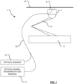
- FIG. 1 a schematic representation of the monitoring system 1.
- the system comprises a conducting block 3 and a carrier 7 (otherwise collectively known as a "pan head") for the block 3 that together form a current collector 5.
- the current collector 5 is coupled to a mechanism 9 for raising or lowering the carrier 7 and conducting block 3 with respect to an electric vehicle 11.
- the mechanism 9 is configured to urge the conducting block 3 into abutment, in this particular arrangement, with an overhead conducting line (OCL) 13 so that current may be drawn from the OCL 13 and supplied to the vehicle 11.
- OCL overhead conducting line
- the conducting block 3 can be of any suitable conducting material.
- the conducting block is - at least principally - of carbon.
- the conducting block 3 includes a plurality of sensor modules (not shown in Fig. 1 ) that are, in this particular arrangement, coupled in series to one another and to an optical source 15 and an optical signal interpretation module 17 by means of optical coupling means that comprises an optic fibre 19.
- the optical coupling means comprises a plurality of optic fibres with each said fibre of said plurality coupling a said sensor module of said plurality to the optical source 15 and the optical signal interpretation module 17.
- the optical source 15 comprises a broadband (i.e. wide spectrum) light source, for example a broadband LED light source.
- a broadband LED light source for example a broadband LED light source.
- the light source could comprise a narrow wavelength source, such as a laser light source, and in this configuration signals from respective sensor modules may be distinguished from one another on the basis of the time of flight of signals between the source and the modules, that is to say the time elapsed between illumination of the sensor modules by the source and the receipt of signals back from the individual sensor modules.
- the optical signal interpretation module 17 can have many different forms, but in one envisaged arrangement the module 17 comprises an optical signal analyser 21 coupled to the optic fibre 19, and a computing resource 23 such as a personal computer (PC) or equivalent.
- the computing resource includes an integral data store 25 for the storage of data, but it will be appreciated that the data store may be external to the module 17.
- the computing resource 23 is coupled to a position determination module 27 that may comprise a GPS device that is adapted to determine the position of the module (and hence any vehicle to which it is affixed) by triangulation using signals from satellites orbiting the earth.
- a position determination module 27 may comprise a GPS device that is adapted to determine the position of the module (and hence any vehicle to which it is affixed) by triangulation using signals from satellites orbiting the earth.
- Other position determination modules such as a module that implements dead-reckoning functionality, may instead be provided without departing from the scope of the invention.
- each array comprises a plurality of FBG sensors arranged in a geometric pattern.
- each array comprises three FBG sensors arranged in a triangle, referred to herein as a "rosette layout" of FBGs. This arrangement allows the correlation of adjacent FBGs, rather than the absolute (or differential) wavelength shift of a thermal FBG, for temperature compensation.
- a fibre that comprises nine FBG-based sensors which are arranged in three-sensor rosettes is integrated into each pan-head (for example, adhered to the pan-head so that the rosettes lie between the pan-head and the carbon collector) and connected to the interrogation unit for data logging.
- Figure 3 shows a typical rosette layout that avoids complex cable routing down the pantograph arm and allows adequate connection of the fibres to the interrogation system.
- each rosette includes three FBGs, each being sensitive to both strain (force caused) and temperature changes.
- S T 1 C T 13 ⁇ S T 3
- S F 1 C F 13 ⁇ S F 3
- C T13 and C F13 are the correlation coefficients of temperature and force sensitivities of the two FBGs, respectively
- Equation (4) the temperature induced wavelength shift is no longer included in the equation used for the calculation of the applied force F. In other words, temperature compensation has been successfully achieved.
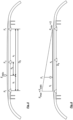
- three FBG sensor rosettes are integrated into the aluminium bottom of a pan-head at three different locations, labelled respectively left, central and right, as illustrated in Figure 4 .
- the areas which are covered with strain rosettes are spaced by 27 cm from the central rosette.
- the schematic diagram of the arrangement of three rosettes and the fibre routing on the pan-head is shown in Figure 2 .
- Figure 7 illustrates the forces that are acting on a pantograph.
- F static is measured using Equation (11) based on the data obtained from the FBG rosettes as described above.
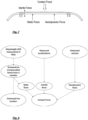
- the overall contact force measurement process can thus be summarized using a flow chart as shown in Figure 8 , showing the underpinning methodology used for the propriety software development for the contact force measurement.
- Equation (16) summarise the overall contact force calculation which consists of static force, inertial force and aerodynamic force:
- FIG. 9 shows a cross-comparison between the measured contact force of a pantograph with built-in sensors and closed-loop control, and the required contact force documented in BS EN 50367 when a train is running at different speeds. It is apparent from Fig. 9 that a very good agreement has been reached.
- the required contact force is derived from the standards document and is related to the speed of a train.
- the real time measured force is used as a feedback to the control valve in order to adjust the force to its required value.
- the control is using PID (proportional-integral-derivative) technique and the system continuously calculates an error value e ( t ) which is the difference between the required and measured contact forces and applies a correction based on proportional, integral, and derivative terms.
- the control system attempts to minimize the error over time by adjusting the input voltage of control valve wired to the pantograph.
- V ( t ) is the correction voltage of the control valve.
- K p , K i and K d are coefficients of the proportional, integral and derivative terms that are obtained through calibration.
- F aim is the required contact force. The difference between the aimed and measured forces, e ( t ), is thus reduced by varying the input voltage of the control valve.
- the flow chart of the control system is shown in Figure 10 .
- the system may include a position sensing module operable to determine the geographic position of the pantograph (so that any detected defects in the catenary can be logged).
- a position sensing module operable to determine the geographic position of the pantograph (so that any detected defects in the catenary can be logged).
Landscapes
- Engineering & Computer Science (AREA)
- Power Engineering (AREA)
- Transportation (AREA)
- Mechanical Engineering (AREA)
- Physics & Mathematics (AREA)
- General Physics & Mathematics (AREA)
- Current-Collector Devices For Electrically Propelled Vehicles (AREA)
- Length Measuring Devices By Optical Means (AREA)
- Measuring Temperature Or Quantity Of Heat (AREA)
- Optical Transform (AREA)
Claims (15)
- Système de surveillance (1) pour un véhicule électrique (11) qui tire du courant d'un conducteur au moyen d'un collecteur de courant (3) qui est en contact avec un conducteur (13) lors du fonctionnement du véhicule, le système comprenant :une pluralité de modules de capteurs configurés pour être répartis à intervalles espacés sur toute la longueur du collecteur de courant, dans lequel chaque module de capteur comprend trois capteurs FBG, à savoir des capteurs fibre à réseau de Bragg (FBG1 à FBG9), disposés dans un plan commun et configurés pour être posés à plat sur une tête panoramique de pantographe,chaque dit module (FBG1 à 3 ; FBG4 à 6 ; FBG7 à 9) étant constitué uniquement de capteurs FBG qui réagissent en utilisation à la fois à la température et à la contrainte, dans lequel les capteurs de chaque dit module sont en étroite proximité les uns avec les autres de sorte que la performance de température des capteurs soit similaire et sont disposés selon un motif triangulaire avec un angle d'environ 60 degrés entre les capteurs adjacents de sorte que les changements de longueur d'onde induits par la température dans les capteurs FBG de chaque module puissent être compensés ;une source optique (15) pour éclairer chaque module de capteur ;des moyens (19) pour coupler optiquement ladite source optique (15) à chaque dit module de capteur; etun module d'interprétation de signaux optiques (17) configuré pour recevoir des signaux optiques provenant de chaque dit module de capteur via lesdits moyens de couplage optique, lesdits signaux optiques étant générés par lesdits modules de capteurs en réponse à l'éclairage desdits modules de capteurs par ladite source optique, ledit module d'interprétation étant configuré pour être capable de corréler mathématiquement les signaux optiques provenant d'au moins deux capteurs dans chaque module de capteur pour compenser les changements de longueur d'onde induits par la température dans les capteurs FBG de chaque module et fournissent ainsi une mesure de contrainte indépendante de la température pour chaque dit module de capteur.
- Système selon la revendication 1, dans lequel ledit module d'interprétation (17) est en outre configuré pour être capable de déterminer la position du conducteur par rapport à la surface du collecteur de courant qui est en contact avec ledit conducteur.
- Système selon l'une quelconque des revendications précédentes, ledit système comprenant ledit collecteur de courant, dans lequel le collecteur de courant comprend
un support (7) et un bloc conducteur (3) monté sur celui-ci, le bloc conducteur étant agencé pour être en contact avec le conducteur lors du fonctionnement du véhicule. - Système selon la revendication 3, dans lequel le support (7) comprend une tête panoramique.
- Système selon la revendication 3 ou 4, dans lequel ledit bloc conducteur est en carbone.
- Système selon l'une quelconque des revendications 3 à 5, dans lequel lesdits modules de capteurs sont prévus entre ledit support (7) et le bloc conducteur (3) dudit collecteur de courant.
- Système selon la revendication 6, dans lequel un premier desdits trois modules de capteurs est situé à peu près au centre dudit collecteur de courant, et un deuxième et un troisième desdits trois modules de capteurs sont situés de chaque côté dudit premier module situé au centre.
- Système selon l'une quelconque des revendications précédentes, comprenant en outre un module de détermination de position (27) pour déterminer la position géographique du véhicule électrique.
- Système selon la revendication 8, dans lequel ledit module de détermination de position (27) comprend un module GPS.
- Système selon l'une quelconque des revendications précédentes, comprenant en outre des moyens pour stocker des données (25), lesdits moyens pour stocker des données étant configurés pour stocker une ou plusieurs parmi : des données de température, des données de contrainte, des données de position de conducteur et des données de position de véhicule.
- Système selon l'une quelconque des revendications précédentes, dans lequel lesdits moyens de couplage optique comprennent une pluralité de fibres optiques, chaque fibre de ladite pluralité étant couplée à l'un desdits modules de capteurs.
- Système selon l'une quelconque des revendications 1 à 10, dans lequel lesdits moyens de couplage optique comprennent une fibre optique (19), lesdits modules de capteurs étant couplés optiquement entre eux et à ladite source par ladite fibre optique.
- Système selon la revendication 12, dans lequel ledit module d'interprétation de signal est configuré pour distinguer les modules de capteurs individuels de ladite pluralité sur la base du temps écoulé entre l'éclairage desdits modules de capteurs avec ladite source et le temps de réception des signaux provenant de chaque dit module.
- Système selon la revendication 12, dans lequel chaque dit module de capteur est configuré pour générer une réponse dans une plage de longueurs d'onde/fréquence unique prédéterminée et ledit module d'interprétation de signal est configuré pour distinguer les signaux provenant des modules de capteurs respectifs en déterminant dans quelle plage de longueurs d'onde/fréquence lesdits signaux se situent.
- Système selon la revendication 3 et facultativement selon l'une quelconque des revendications 4 à 14, comprenant en outre un processeur (23) opérationnel pour déterminer la contrainte appliquée audit collecteur de courant, ledit processeur étant couplé - dans une boucle de rétroaction - à des moyens opérationnels pour augmenter ou diminuer dans quelle mesure ledit collecteur de courant porte sur ledit conducteur.
Applications Claiming Priority (2)
| Application Number | Priority Date | Filing Date | Title |
|---|---|---|---|
| GBGB1700573.7A GB201700573D0 (en) | 2017-01-12 | 2017-01-12 | Optical monitoring system |
| PCT/EP2018/025006 WO2018130427A2 (fr) | 2017-01-12 | 2018-01-12 | Système de surveillance optique |
Publications (3)
| Publication Number | Publication Date |
|---|---|
| EP3568312A2 EP3568312A2 (fr) | 2019-11-20 |
| EP3568312C0 EP3568312C0 (fr) | 2023-12-27 |
| EP3568312B1 true EP3568312B1 (fr) | 2023-12-27 |
Family
ID=58463298
Family Applications (1)
| Application Number | Title | Priority Date | Filing Date |
|---|---|---|---|
| EP18709259.8A Active EP3568312B1 (fr) | 2017-01-12 | 2018-01-12 | Système de surveillance optique |
Country Status (6)
| Country | Link |
|---|---|
| US (1) | US11385110B2 (fr) |
| EP (1) | EP3568312B1 (fr) |
| CN (1) | CN110382284A (fr) |
| ES (1) | ES2971039T3 (fr) |
| GB (2) | GB201700573D0 (fr) |
| WO (1) | WO2018130427A2 (fr) |
Families Citing this family (4)
| Publication number | Priority date | Publication date | Assignee | Title |
|---|---|---|---|---|
| US20220204061A1 (en) * | 2012-08-10 | 2022-06-30 | Transportation Ip Holdings, Llc | Examining system and method |
| US10807621B2 (en) * | 2017-01-23 | 2020-10-20 | Broadsens Corp. | Train pantograph structural health monitoring system |
| CN110514131B (zh) * | 2019-08-26 | 2021-01-19 | 西安交通大学 | 一种智能层式光纤光栅二维应变传感器 |
| CN113049152A (zh) * | 2021-03-01 | 2021-06-29 | 深圳市简测智能技术有限公司 | 一种弓网动态接触力监测系统及方法 |
Family Cites Families (14)
| Publication number | Priority date | Publication date | Assignee | Title |
|---|---|---|---|---|
| DE19725906C1 (de) * | 1997-06-13 | 1999-02-18 | Abb Daimler Benz Transp | Einrichtung zur Messung der Anpreßkraft an einem Stromabnehmer |
| GB2326471B (en) * | 1997-06-19 | 2001-05-30 | British Aerospace | A strain isolated optical fibre bragg grating sensor |
| GB9824756D0 (en) * | 1998-11-11 | 1999-01-06 | Europ Economic Community | A strain sensor and strain sensing apparatus |
| GB2408570B (en) | 2003-10-31 | 2005-11-23 | Morganite Elect Carbon | Monitoring system for electrical vehicles drawing current from overhead conductors |
| FR2864202B1 (fr) * | 2003-12-22 | 2006-08-04 | Commissariat Energie Atomique | Dispositif tubulaire instrumente pour le transport d'un fluide sous pression |
| EP1869413A1 (fr) * | 2005-04-05 | 2007-12-26 | Agency for Science, Technology and Research | Detecteur de reseau de bragg dans une fibre |
| GB0508574D0 (en) * | 2005-04-27 | 2005-06-01 | Morganite Elect Carbon | Monitoring system for electrical vehicles drawing current from conductors |
| DE102005024202A1 (de) * | 2005-05-25 | 2006-11-30 | Siemens Ag | Kraftmesseinrichtung und Verfahren zur Bestimmung einer Kontaktkraft |
| DE102007015180A1 (de) | 2007-03-29 | 2008-10-09 | Siemens Ag | Kraftmesszelle, Kontaktkraftmesseinrichtung und Verfahren zur Messung einer Kontaktkraft zwischen einem Stromabnehmer und einer Stromleitung |
| CN102278947B (zh) * | 2011-04-29 | 2013-04-24 | 大连理工大学 | 用于沥青混凝土路面应变、裂纹测试的封装fbg传感器 |
| GB2511473A (en) * | 2012-11-07 | 2014-09-10 | Univ City | Optical monitoring system |
| CN102944613B (zh) * | 2012-11-16 | 2015-04-01 | 中国科学院半导体研究所 | 一种光纤声发射检测与定位系统 |
| FR3014200B1 (fr) * | 2013-12-02 | 2017-05-26 | Commissariat Energie Atomique | Controle de structure industrielle |
| DE102016014280B4 (de) * | 2016-11-30 | 2018-07-12 | Hottinger Baldwin Messtechnik Gmbh | Anschweißbare FBG-Dehnungssensoranordnung |
-
2017
- 2017-01-12 GB GBGB1700573.7A patent/GB201700573D0/en not_active Ceased
-
2018
- 2018-01-12 WO PCT/EP2018/025006 patent/WO2018130427A2/fr not_active Ceased
- 2018-01-12 EP EP18709259.8A patent/EP3568312B1/fr active Active
- 2018-01-12 GB GB1911494.1A patent/GB2572935B/en active Active
- 2018-01-12 US US16/477,375 patent/US11385110B2/en active Active
- 2018-01-12 CN CN201880006886.7A patent/CN110382284A/zh active Pending
- 2018-01-12 ES ES18709259T patent/ES2971039T3/es active Active
Also Published As
| Publication number | Publication date |
|---|---|
| WO2018130427A3 (fr) | 2018-08-30 |
| EP3568312A2 (fr) | 2019-11-20 |
| EP3568312C0 (fr) | 2023-12-27 |
| US20200055401A1 (en) | 2020-02-20 |
| GB2572935A (en) | 2019-10-16 |
| GB201700573D0 (en) | 2017-03-01 |
| CN110382284A (zh) | 2019-10-25 |
| GB201911494D0 (en) | 2019-09-25 |
| WO2018130427A2 (fr) | 2018-07-19 |
| US11385110B2 (en) | 2022-07-12 |
| GB2572935B (en) | 2022-04-20 |
| ES2971039T3 (es) | 2024-06-03 |
Similar Documents
| Publication | Publication Date | Title |
|---|---|---|
| EP3568312B1 (fr) | Système de surveillance optique | |
| JP7045235B2 (ja) | 輸送監視システム | |
| Schröder et al. | An approach to continuous on-site monitoring of contact forces in current collectors by a fiber optic sensing system | |
| CN103465935B (zh) | 铁路落石预警方法 | |
| Boffi et al. | Optical fiber sensors to measure collector performance in the pantograph-catenary interaction | |
| US10556605B2 (en) | Railway guide system including sensors fixed to a rail | |
| JP4954733B2 (ja) | パンタグラフの接触力測定方法及び接触力測定装置 | |
| JP2000230935A (ja) | 加速度計およびこれを備えた加速度計測装置 | |
| US9587995B2 (en) | Optical monitoring system | |
| CN113661385A (zh) | 光纤传感器单元、光学测量系统、计轴装置及计轴方法 | |
| WO2025153209A1 (fr) | Procédé et dispositif basés sur des ondes progressives pour surveiller l'intensité de vibration dans des lignes électriques aériennes | |
| CN209904774U (zh) | 一种长距离、高精度和可切换的地铁轨道监测系统 | |
| Schröder et al. | Fibre optic sensing system for monitoring of current collectors and overhead contact lines of railways | |
| CN105783777B (zh) | 基于光纤光栅传感的铁路轨道线形在线监测装置和方法 | |
| Chen et al. | A temperature compensated fibre Bragg grating (FBG)-based sensor system for condition monitoring of electrified railway pantograph | |
| Comolli et al. | First results from in line strain measurements with FBG sensors on the pantograph collector of underground trains | |
| Ecke et al. | On-line characterization of impacts on electrical train current collectors using integrated optical fiber grating sensor network | |
| Laffont et al. | Innovative FBG sensing techniques for the railway industry: application to overhead contact line monitoring | |
| Kluth et al. | Case studies on distributed temperature and strain sensing (DTSS) by using optic fibre | |
| Bocciolone et al. | Comparison of optical and electrical measurements of the pantograph-catenary contact force | |
| Boffi et al. | Fiber sensor for collector strain monitoring in the pantograph-catenary interaction | |
| Bocciolone et al. | An application of FBG accelerometers for monitoring pantographs of underground trains | |
| Sun et al. | Optical fibre sensing: A solution for industry | |
| Schröder et al. | Fibre optic sensing system for monitoring of current collectors and catenary of railways | |
| JP2026065460A (ja) | 構造物解析システム、および構造物解析方法 |
Legal Events
| Date | Code | Title | Description |
|---|---|---|---|
| STAA | Information on the status of an ep patent application or granted ep patent |
Free format text: STATUS: UNKNOWN |
|
| STAA | Information on the status of an ep patent application or granted ep patent |
Free format text: STATUS: THE INTERNATIONAL PUBLICATION HAS BEEN MADE |
|
| PUAI | Public reference made under article 153(3) epc to a published international application that has entered the european phase |
Free format text: ORIGINAL CODE: 0009012 |
|
| STAA | Information on the status of an ep patent application or granted ep patent |
Free format text: STATUS: REQUEST FOR EXAMINATION WAS MADE |
|
| 17P | Request for examination filed |
Effective date: 20190812 |
|
| AK | Designated contracting states |
Kind code of ref document: A2 Designated state(s): AL AT BE BG CH CY CZ DE DK EE ES FI FR GB GR HR HU IE IS IT LI LT LU LV MC MK MT NL NO PL PT RO RS SE SI SK SM TR |
|
| AX | Request for extension of the european patent |
Extension state: BA ME |
|
| DAV | Request for validation of the european patent (deleted) | ||
| DAX | Request for extension of the european patent (deleted) | ||
| STAA | Information on the status of an ep patent application or granted ep patent |
Free format text: STATUS: EXAMINATION IS IN PROGRESS |
|
| 17Q | First examination report despatched |
Effective date: 20211105 |
|
| GRAP | Despatch of communication of intention to grant a patent |
Free format text: ORIGINAL CODE: EPIDOSNIGR1 |
|
| STAA | Information on the status of an ep patent application or granted ep patent |
Free format text: STATUS: GRANT OF PATENT IS INTENDED |
|
| INTG | Intention to grant announced |
Effective date: 20230517 |
|
| GRAJ | Information related to disapproval of communication of intention to grant by the applicant or resumption of examination proceedings by the epo deleted |
Free format text: ORIGINAL CODE: EPIDOSDIGR1 |
|
| STAA | Information on the status of an ep patent application or granted ep patent |
Free format text: STATUS: EXAMINATION IS IN PROGRESS |
|
| INTC | Intention to grant announced (deleted) | ||
| GRAS | Grant fee paid |
Free format text: ORIGINAL CODE: EPIDOSNIGR3 |
|
| STAA | Information on the status of an ep patent application or granted ep patent |
Free format text: STATUS: GRANT OF PATENT IS INTENDED |
|
| GRAP | Despatch of communication of intention to grant a patent |
Free format text: ORIGINAL CODE: EPIDOSNIGR1 |
|
| GRAA | (expected) grant |
Free format text: ORIGINAL CODE: 0009210 |
|
| STAA | Information on the status of an ep patent application or granted ep patent |
Free format text: STATUS: THE PATENT HAS BEEN GRANTED |
|
| INTG | Intention to grant announced |
Effective date: 20231114 |
|
| AK | Designated contracting states |
Kind code of ref document: B1 Designated state(s): AL AT BE BG CH CY CZ DE DK EE ES FI FR GB GR HR HU IE IS IT LI LT LU LV MC MK MT NL NO PL PT RO RS SE SI SK SM TR |
|
| RAP3 | Party data changed (applicant data changed or rights of an application transferred) |
Owner name: CITY, UNIVERSITY OF LONDON |
|
| REG | Reference to a national code |
Ref country code: GB Ref legal event code: FG4D |
|
| REG | Reference to a national code |
Ref country code: CH Ref legal event code: EP |
|
| REG | Reference to a national code |
Ref country code: DE Ref legal event code: R096 Ref document number: 602018063163 Country of ref document: DE |
|
| REG | Reference to a national code |
Ref country code: IE Ref legal event code: FG4D |
|
| U01 | Request for unitary effect filed |
Effective date: 20240126 |
|
| U07 | Unitary effect registered |
Designated state(s): AT BE BG DE DK EE FI FR IT LT LU LV MT NL PT SE SI Effective date: 20240205 |
|
| PG25 | Lapsed in a contracting state [announced via postgrant information from national office to epo] |
Ref country code: GR Free format text: LAPSE BECAUSE OF FAILURE TO SUBMIT A TRANSLATION OF THE DESCRIPTION OR TO PAY THE FEE WITHIN THE PRESCRIBED TIME-LIMIT Effective date: 20240328 |
|
| U20 | Renewal fee for the european patent with unitary effect paid |
Year of fee payment: 7 Effective date: 20240315 |
|
| PG25 | Lapsed in a contracting state [announced via postgrant information from national office to epo] |
Ref country code: GR Free format text: LAPSE BECAUSE OF FAILURE TO SUBMIT A TRANSLATION OF THE DESCRIPTION OR TO PAY THE FEE WITHIN THE PRESCRIBED TIME-LIMIT Effective date: 20240328 |
|
| PG25 | Lapsed in a contracting state [announced via postgrant information from national office to epo] |
Ref country code: RS Free format text: LAPSE BECAUSE OF FAILURE TO SUBMIT A TRANSLATION OF THE DESCRIPTION OR TO PAY THE FEE WITHIN THE PRESCRIBED TIME-LIMIT Effective date: 20231227 Ref country code: NO Free format text: LAPSE BECAUSE OF FAILURE TO SUBMIT A TRANSLATION OF THE DESCRIPTION OR TO PAY THE FEE WITHIN THE PRESCRIBED TIME-LIMIT Effective date: 20240327 Ref country code: HR Free format text: LAPSE BECAUSE OF FAILURE TO SUBMIT A TRANSLATION OF THE DESCRIPTION OR TO PAY THE FEE WITHIN THE PRESCRIBED TIME-LIMIT Effective date: 20231227 |
|
| REG | Reference to a national code |
Ref country code: ES Ref legal event code: FG2A Ref document number: 2971039 Country of ref document: ES Kind code of ref document: T3 Effective date: 20240603 |
|
| PG25 | Lapsed in a contracting state [announced via postgrant information from national office to epo] |
Ref country code: IS Free format text: LAPSE BECAUSE OF FAILURE TO SUBMIT A TRANSLATION OF THE DESCRIPTION OR TO PAY THE FEE WITHIN THE PRESCRIBED TIME-LIMIT Effective date: 20240427 |
|
| PG25 | Lapsed in a contracting state [announced via postgrant information from national office to epo] |
Ref country code: CZ Free format text: LAPSE BECAUSE OF FAILURE TO SUBMIT A TRANSLATION OF THE DESCRIPTION OR TO PAY THE FEE WITHIN THE PRESCRIBED TIME-LIMIT Effective date: 20231227 |
|
| PG25 | Lapsed in a contracting state [announced via postgrant information from national office to epo] |
Ref country code: SK Free format text: LAPSE BECAUSE OF FAILURE TO SUBMIT A TRANSLATION OF THE DESCRIPTION OR TO PAY THE FEE WITHIN THE PRESCRIBED TIME-LIMIT Effective date: 20231227 |
|
| PG25 | Lapsed in a contracting state [announced via postgrant information from national office to epo] |
Ref country code: SM Free format text: LAPSE BECAUSE OF FAILURE TO SUBMIT A TRANSLATION OF THE DESCRIPTION OR TO PAY THE FEE WITHIN THE PRESCRIBED TIME-LIMIT Effective date: 20231227 Ref country code: SK Free format text: LAPSE BECAUSE OF FAILURE TO SUBMIT A TRANSLATION OF THE DESCRIPTION OR TO PAY THE FEE WITHIN THE PRESCRIBED TIME-LIMIT Effective date: 20231227 Ref country code: RO Free format text: LAPSE BECAUSE OF FAILURE TO SUBMIT A TRANSLATION OF THE DESCRIPTION OR TO PAY THE FEE WITHIN THE PRESCRIBED TIME-LIMIT Effective date: 20231227 Ref country code: IS Free format text: LAPSE BECAUSE OF FAILURE TO SUBMIT A TRANSLATION OF THE DESCRIPTION OR TO PAY THE FEE WITHIN THE PRESCRIBED TIME-LIMIT Effective date: 20240427 Ref country code: CZ Free format text: LAPSE BECAUSE OF FAILURE TO SUBMIT A TRANSLATION OF THE DESCRIPTION OR TO PAY THE FEE WITHIN THE PRESCRIBED TIME-LIMIT Effective date: 20231227 |
|
| PG25 | Lapsed in a contracting state [announced via postgrant information from national office to epo] |
Ref country code: PL Free format text: LAPSE BECAUSE OF FAILURE TO SUBMIT A TRANSLATION OF THE DESCRIPTION OR TO PAY THE FEE WITHIN THE PRESCRIBED TIME-LIMIT Effective date: 20231227 |
|
| PG25 | Lapsed in a contracting state [announced via postgrant information from national office to epo] |
Ref country code: PL Free format text: LAPSE BECAUSE OF FAILURE TO SUBMIT A TRANSLATION OF THE DESCRIPTION OR TO PAY THE FEE WITHIN THE PRESCRIBED TIME-LIMIT Effective date: 20231227 |
|
| REG | Reference to a national code |
Ref country code: CH Ref legal event code: PL |
|
| PG25 | Lapsed in a contracting state [announced via postgrant information from national office to epo] |
Ref country code: MC Free format text: LAPSE BECAUSE OF FAILURE TO SUBMIT A TRANSLATION OF THE DESCRIPTION OR TO PAY THE FEE WITHIN THE PRESCRIBED TIME-LIMIT Effective date: 20231227 |
|
| REG | Reference to a national code |
Ref country code: DE Ref legal event code: R097 Ref document number: 602018063163 Country of ref document: DE |
|
| PG25 | Lapsed in a contracting state [announced via postgrant information from national office to epo] |
Ref country code: CH Free format text: LAPSE BECAUSE OF NON-PAYMENT OF DUE FEES Effective date: 20240131 |
|
| PG25 | Lapsed in a contracting state [announced via postgrant information from national office to epo] |
Ref country code: CH Free format text: LAPSE BECAUSE OF NON-PAYMENT OF DUE FEES Effective date: 20240131 |
|
| PLBE | No opposition filed within time limit |
Free format text: ORIGINAL CODE: 0009261 |
|
| STAA | Information on the status of an ep patent application or granted ep patent |
Free format text: STATUS: NO OPPOSITION FILED WITHIN TIME LIMIT |
|
| 26N | No opposition filed |
Effective date: 20240930 |
|
| PG25 | Lapsed in a contracting state [announced via postgrant information from national office to epo] |
Ref country code: IE Free format text: LAPSE BECAUSE OF NON-PAYMENT OF DUE FEES Effective date: 20240112 |
|
| PG25 | Lapsed in a contracting state [announced via postgrant information from national office to epo] |
Ref country code: IE Free format text: LAPSE BECAUSE OF NON-PAYMENT OF DUE FEES Effective date: 20240112 |
|
| U20 | Renewal fee for the european patent with unitary effect paid |
Year of fee payment: 8 Effective date: 20250130 |
|
| PG25 | Lapsed in a contracting state [announced via postgrant information from national office to epo] |
Ref country code: CY Free format text: LAPSE BECAUSE OF FAILURE TO SUBMIT A TRANSLATION OF THE DESCRIPTION OR TO PAY THE FEE WITHIN THE PRESCRIBED TIME-LIMIT; INVALID AB INITIO Effective date: 20180112 |
|
| PG25 | Lapsed in a contracting state [announced via postgrant information from national office to epo] |
Ref country code: HU Free format text: LAPSE BECAUSE OF FAILURE TO SUBMIT A TRANSLATION OF THE DESCRIPTION OR TO PAY THE FEE WITHIN THE PRESCRIBED TIME-LIMIT; INVALID AB INITIO Effective date: 20180112 |
|
| PG25 | Lapsed in a contracting state [announced via postgrant information from national office to epo] |
Ref country code: TR Free format text: LAPSE BECAUSE OF FAILURE TO SUBMIT A TRANSLATION OF THE DESCRIPTION OR TO PAY THE FEE WITHIN THE PRESCRIBED TIME-LIMIT Effective date: 20231227 |
|
| U20 | Renewal fee for the european patent with unitary effect paid |
Year of fee payment: 9 Effective date: 20260130 |
|
| PGFP | Annual fee paid to national office [announced via postgrant information from national office to epo] |
Ref country code: GB Payment date: 20260216 Year of fee payment: 9 |
|
| PGFP | Annual fee paid to national office [announced via postgrant information from national office to epo] |
Ref country code: ES Payment date: 20260205 Year of fee payment: 9 |