EP3568715B1 - Dispositif sportif électronique sans fil portable - Google Patents
Dispositif sportif électronique sans fil portable Download PDFInfo
- Publication number
- EP3568715B1 EP3568715B1 EP18702570.5A EP18702570A EP3568715B1 EP 3568715 B1 EP3568715 B1 EP 3568715B1 EP 18702570 A EP18702570 A EP 18702570A EP 3568715 B1 EP3568715 B1 EP 3568715B1
- Authority
- EP
- European Patent Office
- Prior art keywords
- imu
- sports device
- frequency
- global positioning
- filter
- Prior art date
- Legal status (The legal status is an assumption and is not a legal conclusion. Google has not performed a legal analysis and makes no representation as to the accuracy of the status listed.)
- Active
Links
Images


Classifications
-
- G—PHYSICS
- G01—MEASURING; TESTING
- G01S—RADIO DIRECTION-FINDING; RADIO NAVIGATION; DETERMINING DISTANCE OR VELOCITY BY USE OF RADIO WAVES; LOCATING OR PRESENCE-DETECTING BY USE OF THE REFLECTION OR RERADIATION OF RADIO WAVES; ANALOGOUS ARRANGEMENTS USING OTHER WAVES
- G01S19/00—Satellite radio beacon positioning systems; Determining position, velocity or attitude using signals transmitted by such systems
- G01S19/01—Satellite radio beacon positioning systems transmitting time-stamped messages, e.g. GPS [Global Positioning System], GLONASS [Global Orbiting Navigation Satellite System] or GALILEO
- G01S19/13—Receivers
- G01S19/14—Receivers specially adapted for specific applications
- G01S19/19—Sporting applications
-
- G—PHYSICS
- G01—MEASURING; TESTING
- G01S—RADIO DIRECTION-FINDING; RADIO NAVIGATION; DETERMINING DISTANCE OR VELOCITY BY USE OF RADIO WAVES; LOCATING OR PRESENCE-DETECTING BY USE OF THE REFLECTION OR RERADIATION OF RADIO WAVES; ANALOGOUS ARRANGEMENTS USING OTHER WAVES
- G01S19/00—Satellite radio beacon positioning systems; Determining position, velocity or attitude using signals transmitted by such systems
- G01S19/01—Satellite radio beacon positioning systems transmitting time-stamped messages, e.g. GPS [Global Positioning System], GLONASS [Global Orbiting Navigation Satellite System] or GALILEO
- G01S19/13—Receivers
- G01S19/35—Constructional details or hardware or software details of the signal processing chain
-
- G—PHYSICS
- G01—MEASURING; TESTING
- G01S—RADIO DIRECTION-FINDING; RADIO NAVIGATION; DETERMINING DISTANCE OR VELOCITY BY USE OF RADIO WAVES; LOCATING OR PRESENCE-DETECTING BY USE OF THE REFLECTION OR RERADIATION OF RADIO WAVES; ANALOGOUS ARRANGEMENTS USING OTHER WAVES
- G01S19/00—Satellite radio beacon positioning systems; Determining position, velocity or attitude using signals transmitted by such systems
- G01S19/38—Determining a navigation solution using signals transmitted by a satellite radio beacon positioning system
- G01S19/39—Determining a navigation solution using signals transmitted by a satellite radio beacon positioning system the satellite radio beacon positioning system transmitting time-stamped messages, e.g. GPS [Global Positioning System], GLONASS [Global Orbiting Navigation Satellite System] or GALILEO
- G01S19/42—Determining position
- G01S19/48—Determining position by combining or switching between position solutions derived from the satellite radio beacon positioning system and position solutions derived from a further system
- G01S19/49—Determining position by combining or switching between position solutions derived from the satellite radio beacon positioning system and position solutions derived from a further system whereby the further system is an inertial position system, e.g. loosely-coupled
Definitions
- the present invention is in the field of a wearable wireless sports device, such as for a bicycle.
- the device is capable of providing information relating to the sport and to the user of the device, such as velocity and distance travelled.
- the present invention is in the field of a wearable wireless sports device.
- Wearable technology may be related to wearable computers or the like.
- an effort has been made to enhance functionality of clothing and to create wearables as accessories able to provide users with monitoring an activity, typically by way of small wearable or portable personal device.
- Tracking information such as movement, steps, and heart rate, are typical components of such activities.
- Examples of such a wearable devices are a wearable electronic watch/calculator and a hearing aid. These early devices function as standalone devices and are typically not accessible other than by functional buttons/knobs.
- Tracking devices are known per se, such as for cars, which provide information on e.g. a location and speed of a vehicle. These device are however not very accurate (typically ⁇ 10 m), can not be used under shielded conditions, such as in tunnels or in a wood or forest, and may not be wearable. For cars this may typically not be much of an issue, but for wearables such is.
- Satellite navigation systems have been available for quite some time. There are over 100 satellites orbiting the earth. These satellites are arranged in constellations of global navigation satellite systems (GNSS) that transmit extremely accurate time information. By comparing the signals received from typically four or more satellites, receivers can calculate their position on the earth in terms of latitude and longitude. Until recent only minor revisions to automotive satellite navigation have been made resulting in limitations in use, especially in view of accuracy and reliability, as well as in terms of integration of various aspects of technologies used. The limitations of the GNSS relate to e.g. extremely weak satellite signals.
- GNSS global navigation satellite systems
- signals are so weak (typically a hundred times weaker than a home Wi-Fi signal) anything that interferes with the reception thereof, such as walls, tunnels, forests, garages, an open road lined with tall buildings, results in an inaccurate or no location "fix". In these scenarios a clear line-of-sight to the satellites is blocked and reflections of the signals may occur, which subsequently interfere with the signals coming directly from the satellite and hence making it even more complex to determine an exact position.
- WO 2016/044831 A1 recites a sensing system and wearable sensor platform described herein provide real-time feedback to a user/wearer of his power expenditure during an activity.
- the system may include an inertial measurement unit (IMU) for acquiring multi-axis motion data at a first sampling rate, and an orientation sensor to acquire orientation data at a second sampling rate that is varied based on the multi-axis motion data.
- IMU inertial measurement unit
- US 2016/030807 recites an exercise analysis system including a calculation unit which calculates exercise energy of a user, based on output of an inertial sensor which is put on the user; and a generation unit which generates exercise ability information which is information relating to an exercise ability of the user, based on the exercise energy, a running distance, and a running time.
- WO2012/045483 A1 recites a system that is configured to be transported, carried or worn by a user, such as a portable personal training device or sports watch.
- the system comprises means for determining the location of the user, such as a GPS receiver, means for determining a motion state of the user, which may include an accelerometer, and can also utilise data obtained from a GPS receiver, means for determining the distance travelled by the user such that the system functions as an odometer.
- WO01/42809 A2 recites a system for automatic monitoring real-time athletic performance of a user.
- a portable unit with a GPS receiver capable of providing GPS velocity data to a processor unit is able to provide an updated readout to a display unit, such as elevation gain, current speed, current heading, current elevation, calories burned, anticipated calories burned (based upon a pre-selected course), and others. It uses Doppler shift based GPS velocity measurements. The accuracy is limited to ⁇ 10 m, and only under un-shielded application.
- EP 1 992 389 A1 recites a data logger for monitoring sports which includes an accelerometer, a gyro sensor to sense angular displacement, a GPS unit to sense position and velocity, a magnetometer to sense direction of movement, a heart rate monitor, and a controller programmed to manipulate the data and provide a display of the heart rate, speed, and other sport parameters.
- the data can be stored or transmitted to a remote computer for use by the coach.
- WO03/032516 A1 recites a satellite positioning system receiver for location enabled wireless mobile communication devices having satellite signal receivers, and more particularly to reference oscillator circuits, combinations thereof and methods therefor.
- the method includes determining a change in cellular network based frequency error in a location enabled mobile wireless receiver having an oscillator.
- US2006/084551 A recites a motivational fitness device, which controls the audio output of a television or audio component in response to the heart rate.
- a heart rate sensing device relays heart rate to a processor unit.
- the processor receives and compares the user's heart rate to the specified target range and sends control signals (or not) to the entertainment device.
- the present invention therefore relates to an improved wearable wireless electronic sports device, which solve one or more of the above problems and drawbacks of the prior art, providing reliable results, without jeopardizing functionality and advantages.
- the present invention relates to a wearable wireless electronic sports device 100 according to claim 1.
- GNSS systems 32 such as Glonass, GPS and Galileo
- a global positioning sensor such as Glonass, GPS and Galileo
- the outputs of the IMU and global positioning sensor are fused (see e.g. fig. 3a ).
- the present device comprises an integrated or global positioning sensor (also referred to as receiver or GNSS receiver) and fused therewith an inertial measurement unit (IMU) in a so-called dead reckoning device.
- IMU inertial measurement unit
- the present system is considered to be an open system, in that further sensors, such as a camera, and further input, such as physical characteristics of an environment, can be coupled to the system.
- a filter 44 is provided in order to process data quickly and reliably and to provide physical parameters, such as position, velocity, time, direction, and altitude.
- a filter 44 is provided in order to process data quickly and reliably and to provide physical parameters, such as position, velocity, time, direction, and altitude.
- a filter 44 In electrical connection therewith is typically an accelerometer 42 and/or a gyroscope 43; the accelerometer and/or a gyroscope may be integrated with the above sensor and IMU.
- Information of a vehicle such as a wheel speed of a bicycle, could be provided wireless to the present device; it is noted that typically cars rely on such data in order to provide accurate positioning data.
- the present device can calculate a distance covered without a need of having access to wheel speed information or an odometer.
- This new approach may be referred to as Untethered Dead Reckoning (UDR); it combines all the sensor data together with that of the GNSS data. Integration of annular rates, specific forces, as e.g. identified in fig. 3b , as sensed by the IMU, the IMU preferably having a three (or more) axis gyroscope and a three (or more) axis accelerometer.
- the axes (if 3) are assumed to be orthogonal axes.
- the present device is wearable and can be wireless connected to further devices, such as a smart phone.
- the present transceiver is also used to obtained detailed and accurate information with respect to locations of the one or more satellites of which the present device receives GNSS-input.
- a power source 70 is provided, such as a battery.
- the power source may be chargeable, such as wireless chargeable, or by conductance.
- a central processing unit 60 for processing data from the integrated circuit and for performing functions is provided, such as a Raspberry Pi.
- the present device is preferably integrated into one PCB.
- the processing unit comprises a transceiver for wireless communication with a remote device, such as a smart phone or a computer, a memory, such as for storing data and for pre-use configuring the device and the information displayed, a comparator for comparing physical changes, such as changes in speed, in altitude, in user power, in location, in distance, in user heart frequency, and in movement frequency, and a programming protocol, such as a user interface. Further the present device comprises a comparator for comparing physical changes, such as changes in speed, in altitude, in user power, in location, in distance, in user heart frequency, and in movement frequency. In the device, such as in the comparator or in the CPU, a vehicle model is present.
- the model is an advanced model for determining if parameters measured or changes therein are realistic, e.g. achievable by a cyclist.
- active filtering can be used to remove noise in this respect.
- a dynamic model is present, which for instance will fix a location when a user of the device does not move; thereby GNSS information is ignored, which improves an accuracy with a few meters typically.
- the IMU may also be used, thus typically in combination, to determine absence or presence of movement.
- a programming protocol such as a user interface
- the device optionally comprises a power booster, a magnetic compass, an accelerometer and/or a gyroscope, a damper, such as a mechanical damper or a damper of vibrations, a barometer for determining a relative height and inclination, and a thermometer.
- the magnetic compass may e.g. be used to align the internal IMU axes.
- the thermometer may be used to calibrate the IMU, and specifically the gyroscope and accelerometers thereof. As such a 9-axis sensor may be provided.
- a clock is provided for generating signals in a frequency range of 1-10.000 Hz.
- an antenna 40 is provided for receiving GNSS signals as well as for wireless communication (transceiving).
- the antenna may operate at 1-5 GHz, such as 2000-3000 MHz, such as 2400 MHz-2524 MHz.
- a display 20 is integrated in the body, typically a relatively small display.
- a detachable fixing means is provided to the body of the present device.
- the present invention relates to a use of the present device for location determination within an accuracy of ⁇ 2 m or better in shielded locations, such as ⁇ 1.5 m, and within an accuracy of ⁇ 1 m or better in unshielded locations, such as ⁇ 0.7 m.
- the present invention relates in a first aspect to a sports device according to claim 1.
- a clock time of the global positioning sensor 32 and IMU 31 may be synchronized and/or provided with a time mark, preferably within 1Hz and/or within 10 -3 sec.
- the outputs are synchronized within a very small timeframe, such as within 10 -4 sec or even within 10 -5 sec, and therefore represent an output generated at substantially the same time.
- Any latency is preferably ⁇ 10 ms, such as ⁇ 1 ms.
- the outputs with respect to time are fully consistent and can therefore be used together.
- the respective outputs may be provided with a time mark (actual year, month, day, hour, minutes, second and fraction thereof) and outputs with substantially the same time mark may be used together, or fused.
- the fused data provides the accuracies in location, velocity, yaw, pitch, roll, acceleration, height, etc.
- acceleration output of the global positioning sensor 32 and IMU 31 may be fused, e.g. such as indicated in fig. 3a .
- yaw output of the global positioning sensor 32 and IMU 31 may be fused.
- the yaw output is found to be sufficient to obtain the above accuracies (see also figs. 3a,b ).
- the comparator may be adapted to compare an actual fused output of the global positioning sensor 32 and IMU 31 with a previously predicted value for the output, wherein the output is selected from at least one of location, velocity, roll, pitch, and, according to the invention, yaw.
- the output of the global positioning sensor 32 and IMU 31 is provided to the central processing unit 60 and may be pre-filtered with a signal processing filter before it is provided as input to the central processing unit 60, such as with a maximally flat magnitude filter, such as a Butterworth filter.
- a maximally flat magnitude filter such as a Butterworth filter.
- the Butterworth filter is a type of signal processing filter designed to have an as flat as possible frequency response in a required passband, or a close approximation thereof, especially if enough filter elements are used. It is also referred to as a maximally flat magnitude filter.
- the filter preferably has a first order response roll off of >-20dB per octave, and multitudes thereof for the subsequent order filters.
- fused output of the global positioning sensor 32 and IMU 31 may be provided to a pose unit, and wherein also a physical location determined by the global positioning sensor 32 may be provided to the pose unit. Therewith the fused outputs, possibly being pre-filtered may be provided for further calculations and determining the various parameters.
- the pose unit may provide output with respect to at least one of physical location, roll, pitch, yaw, velocity, and acceleration to the central processing unit. These outputs are used for precise determination of these parameters, amongst others.
- the IMU may be adapted to align at least one internal mount axis with respect to the gravity axis of the earth, preferably automatically align.
- the IMU may be misaligned or get misaligned.
- the internal axes are preferably realigned with respect to the gravity axis of the earth. This may be done manually, such as by using a user interface, or automatically. It is preferred to align when in rest.
- the device is adapted to provide untethered dead reckoning.
- the IMU may use a vehicle reference point (VRP) as reference for calculations, wherein the VRP is located in the center of a vehicles rear axis or axes. It has been found that by using such a precise VRP much better output can be generated.
- VRP vehicle reference point
- an internal IMU frame may correspond to the three (x,y,z) axes of the accelerometer and gyroscope, respectively.
- the x-axis may be considered to point towards a front of the vehicle, the y-axis to a left side of the vehicle, and the z-axis upwards.
- At the most one input selector may be provided, preferably no input selector, and optionally an on/off selector.
- the input selector may be a capacitive sensor.
- the selector may be provided on either side of the device.
- the selector may provide switching between various data screens, paring with wireless devices such as a smartphone, and further functions.
- the selectors may be operated individually or simultaneously. As such the present device is accessible only and completely in a wireless mode. This provides improved flexibility in programming the device and in designing the device.
- the present device may comprise an altimeter.
- an altitude of the use can be provided. Such is especially of interest when climbing or descending a slope, especially when also an inclination is provided.
- the present device may comprise a user power indicator.
- the power (W) generated by a user is considered to be an important aspect when training the body.
- the present device may comprise a user intensity determinator, such as at least one of a stroke determinator (such as when rowing), a peddle frequency determinator (such as when cycling), a step frequency determinator (such as when walking or running), and a heartbeat sensor.
- a stroke determinator such as when rowing
- a peddle frequency determinator such as when cycling
- a step frequency determinator such as when walking or running
- the present device may be for a bicycle, for running, for rowing, or for skiing.
- the display may have a width of 1-7 cm, preferably 2-5 cm, and a height of 2-10 cm, preferably 3-7 cm, and wherein the body may have a thickness of 0.5-2 cm, preferably 1-1.5 cm.
- the device is preferably small in view of wearability, but not too small in view of readability and amount of information on a display
- the power source may provide a current of 1000-7500 mA, preferably 2000-5000 mA, preferably over a period of 1-48 hours, such as 2-16 hours. It is noted that some of the elements of the present device consume a relative large amount of energy which limits its use in time.
- the present device may comprise at least one internal switch for changing content of the display.
- the internal switch may be addressed by a smart phone or the like.
- the present device may comprise at least one of an information filter, an optimizer, and a noise reduction filter, such as a recursive least square filter, such as a Kalman filter, such as an extended Kalman filter, preferably embedded.
- a noise reduction filter such as a recursive least square filter, such as a Kalman filter, such as an extended Kalman filter, preferably embedded.
- the present device may comprise a synchronizer. Therewith accurate fitting of various inputs can be achieved.
- the present device may comprise an analog identifier, for determining a frequency of a GNSS signal with an accuracy of ⁇ ⁇ 100Hz, preferably ⁇ ⁇ 10 Hz, more preferably ⁇ ⁇ 1Hz, and/or for determining a phase of a GNSS signal with an accuracy of ⁇ ⁇ 1%, preferably ⁇ ⁇ 10 -1 %, more preferably ⁇ ⁇ 10 -2 %. Therewith in improved accuracy up to ⁇ 1 m in determining location is obtained.
- the present device may comprise a frequency filter, preferably a frequency filter with a bandwidth of ⁇ 100 kHz, more preferably ⁇ 10 kHz. Therewith a more accurate determination of a location is obtained.
- the present device may comprise comprising a frequency selector, preferably an automatic frequency selector.
- a GNSS system can be selected and use can be made of more data improving an accuracy.
- the present device may be detachable, such as detachable from a holder or a mount.
- the present display may be at angle of -10°-30° relative to the surface of the earth (in a frontward direction from the viewer), preferably -5°-20°, more preferably -2°-10°, such as -0°-5°.
- the present device may have a IP67 body, an IC, a memory of >2Gb, a battery, a 3" color-display, Gorilla glass, a Bluetooth antenna, a Gnss patch antenna, a Ublox EVA m8 navigation system, an IMU, a barometer, a clock, and two capacitive pressure sensors are shown.
- the software may be updated, such as wireless updated.
- Various interface may be present, as well as a website and an app.
- the (user) interface may be controllable by the app, the website the user, or a combination thereof.
- Basic function provides may be time, provided by the RTC, velocity and distance (by the UDR), cadence, heart beat rate and power (by the respective sensors and antenna ANT+), and height, temperature and inclination (by the barometer). For all basic function averages, integrals, derivatives, minimum and maximum values, totals, intervals, etc. may be provided.
- the data may be provided to a database, such as a cloud based database, such as Strava.
- FIG. 1 Schematic representation of a prior art device as detailed above. Therein a gyroscope 43, an accelerometer 42, a GNSS system 32, and a least square filter 44 are shown.
- FIG. 20 shows an example of the present device.
- an IMU 30 is connected via a display pinout 51 to a display 20.
- the display is connected to a CPU 60, which may be a Raspberry Pi especially when testing.
- a Ublox positioning unit 52 attached to an antenna 40 provides input to the CPU.
- the CPU may be reset by a hard reset 61.
- a battery 70 For power a battery 70, and optionally a battery charging unit with charging point 72 and a power switch 71 may be provided.
- Figures 3a-b show schematics of the present physical parameters used. Therein three basic elements, pose, yaw ⁇ and velo v are integrated within one sensor (or receiver), each typically having an x , y and z component.
- the GNSS and IMU are functionally coupled in view of position, course and velocity, and in view of yaw rate and amplitude. Some pre-processing of data may be provided, before transferring data to the processor. Thereafter an extended Kalman filter (EKF) is used to fuse data, and to reduce noise and to increase accuracy.
- Figure 3b shows schematical components as mentioned above for a bicycle model having two wheels, of which the left (front) wheel is rotatable over an angle ⁇ , optionally having an inclination ⁇ .
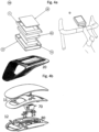
- FIG. 4a,b shows an exemplary device 100. Therein a display 20, a top part of the body 11, a PCB 80 with all electric components integrated therein, a battery 70, and a side/bottom part of the body are shown. According to the invention, the device may be removably attached to a steering wheel of a bicycle.
- FIG 4b a device with a IP67 body, an IC, a memory of >2Gb, a battery, a 3" color-display, Gorilla glass, a Bluetooth antenna, a Gnss patch antenna, a Ublox EVA m8 navigation system, an IMU, a barometer, a clock, and two capacitive pressure sensors are shown.
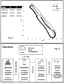
- FIG. 5 comparative results. Therein it can clearly be seen that the Garmin device is fully off track, the GPS device when shielded misses large parts of the track, the very expensive reference device functions fine, as does the present device (EKF), both being largely on track.
- the root mean square deviation (RMSe) is determined from true values determined on the ground. A deviation is given in North (N) and East (E); the smaller the deviation the better. Except for the Garmin tests sensor fusion is applied.
- Figure 6 shows a mode of operation and components. A cyclist having her hands on the steering wheel is shown.
- the sensor of the present device is set as follows:
- Raspberry Pi3 Computer Powerboost 1000C 1A Transformator, Lithium Ion Polymer Battery 3.7v 2500mAh Accu, 9-Dof sensor IMU, piTFT capacitive 320x240 TFT Touchscreen, guitarist microSD 64 GB memory chip, Ublox EVK -7p Gps receiver Ublox, PiCam 8MP Camera, and an Antenna ground plate.
- UDR Untethered Dead Reckoning
- SFDR Sensor Fusion Dead Reckoning
- INS Inertial Navigation System
- IMU 6-degrees-of-freedom Inertial Measurement Unit
- the three-axis gyroscope and accelerometer sense specific forces and angular rates, respectively. Their axes are assumed to be mutually orthogonal.
- the INS computes position, velocity and attitude changes and can, once initialized, provide accurate navigation information. It is noted that an inertial-only navigation solution could degrade quickly with time due to the errors corrupting the IMU observations.
- the integration of the INS with GNSS measurements bounds these time-growing errors by calibrating the INS.
- the resulting integrated INS/GNSS filter referred to as fusion filter in the sequel, has the advantages compared to standalone GNSS positioning, such as an improved navigation performance in GNSS-denied conditions, as errors caused by multipath or weak signal conditions are mitigated though the aid brought by the IMU, and it provides navigation solution during short GNSS-outages: the INS is configured to bridge short GNSS gaps which might be caused such as by tunnels or parking garages.
- the IMU-frame corresponds to the IMU instrumental frame within which the accelerometers and gyroscopes are assumed to be orthogonally mounted.
- the IMU-frame is defined as follows:
- the installation-frame is a right-handed 3D Cartesian frame rigidly connected with the vehicle and is used to define the installation setup required for UDR navigation.
- the installation frame is defined as follows:
- Gyroscope and accelerometer settings are set up and a sensor tim tagging is adapted.
Landscapes
- Engineering & Computer Science (AREA)
- Radar, Positioning & Navigation (AREA)
- Remote Sensing (AREA)
- Computer Networks & Wireless Communication (AREA)
- Physics & Mathematics (AREA)
- General Physics & Mathematics (AREA)
- Signal Processing (AREA)
- Position Fixing By Use Of Radio Waves (AREA)
- Navigation (AREA)
Claims (11)
- Dispositif de sport électronique (100) autonome, sans fil, vestimentaire, pour la navigation à l'estime, destiné à une bicyclette, comprenant(1) un corps à l'épreuve des intempéries, tel qu'un corps IPxy, comprenant dans le corps(1a) une source d'énergie (70) en connexion électrique avec(1b) un circuit intégré (30), le circuit intégré comprenant un capteur de positionnement global (32) adapté pour recevoir une entrée d'un système mondial de navigation par satellite, et une unité de mesure inertielle (IMU) (31), l'IMU étant adaptée pour fournir une sortie filtrée, et dans lequel l'IMU et le capteur de positionnement global sont fusionnés pour fournir une sortie fusionnée, la sortie fusionnée comprenant un taux de lacet, dans lequel en cours d'utilisation, un temps d'horloge du capteur de positionnement global (32) et de l'IMU (31) est synchronisé et/ou pourvu d'un repère de temps,(1c) une unité centrale de traitement (60) pour traiter des données provenant du circuit intégré et pour recevoir une entrée de l'IMU et du système mondial de navigation par satellite, l'unité de traitement comprenant(1d) un émetteur/récepteur pour une communication sans fil avec un dispositif distant,(1e) une mémoire, comme pour stocker des données et pour configurer le dispositif et les informations affichées avant l'utilisation,(1f) un comparateur pour comparer des changements physiques, tels que des changements de vitesse, d'altitude, de puissance de l'utilisateur, d'emplacement, de distance, de fréquence cardiaque de l'utilisateur et de fréquence de mouvement,(1g) un protocole de programmation, tel qu'une interface utilisateur,(1h) en option un amplificateur de puissance,(1i) un accéléromètre (42) et/ou un gyroscope (43),(1j) en option un amortisseur,(1k) en option un thermomètre,(11) une horloge pour générer des signaux dans une plage de fréquence de 1 à 10 000 Hz,(1m) une boussole magnétique,(1n) en option un baromètre, et(10) une antenne (40), et(2) un affichage (20) intégré dans le corps, le corps présentant un moyen de fixation amovible à attacher au guidon d'une bicyclette.
- Dispositif de sport selon l'une quelconque des revendications précédentes, dans lequel la sortie d'accélération du capteur de positionnement global (32) et de l'IMU (31) est fusionnée, et/ou dans lequel la sortie de lacet du capteur de positionnement global (32) et de l'IMU (31) est fusionnée.
- Dispositif de sport selon l'une quelconque des revendications précédentes, dans lequel la sortie fusionnée du capteur de positionnement global (32) et de l'IMU (31) est fournie à une unité de pose, et dans lequel un emplacement physique déterminé par le capteur de positionnement global (32) est également fourni à l'unité de pose.
- Dispositif de sport selon la revendication 9, dans lequel l'unité de pose fournit à l'unité centrale de traitement une sortie concernant au moins un élément parmi un emplacement physique, un taux de roulis, de tangage, de lacet, une vitesse et une accélération.
- Dispositif de sport selon l'une quelconque des revendications précédentes, dans lequel l'IMU est adaptée pour aligner au moins un axe de montage interne par rapport à l'axe de gravité de la terre, de préférence pour l'aligner automatiquement.
- Dispositif de sport selon l'une quelconque des revendications précédentes, dans lequel toutes les données de capteur ainsi que les données de GNSS sont combinées, telles que sélectionnées parmi l'intégration de taux annuels, de forces spécifiques et de données de capteur IMU, l'IMU présentant de préférence un gyroscope à trois axes ou plus et un accéléromètre à trois axes ou plus.
- Dispositif de sport selon l'une quelconque des revendications précédentes, dans lequel l'IMU utilise un point de référence de véhicule (VRP) comme référence pour les calculs, le VRP étant situé au centre d'un axe ou des axes arrière d'un véhicule.
- Dispositif de sport selon l'une quelconque des revendications précédentes, comprenant au moins un filtre d'informations (44), un optimiseur et un filtre de réduction de bruit, tel qu'un filtre des moindres carrés récursifs, tel qu'un filtre de Kalman, de préférence incorporé.
- Dispositif de sport selon l'une quelconque des revendications précédentes, comprenant en outre au moins un élément parmi au plus un seul sélecteur d'entrée, de préférence aucun sélecteur d'entrée, un sélecteur marche/arrêt, un altimètre, un indicateur de la puissance de l'utilisateur, un dispositif de détermination de l'intensité de l'utilisateur, tel qu'au moins un élément parmi un dispositif de détermination de coup de pédale, un dispositif de détermination de fréquence de pédalage, un dispositif de détermination de fréquence de pas, un capteur de battement de coeur, un commutateur interne pour changer d'affichage, un dispositif de synchronisation, un identificateur analogique, pour déterminer une fréquence d'un signal GNSS avec une exactitude de < ±100 Hz, de préférence < ±10 Hz, de plus grande préférence < ±1Hz, et/ou pour déterminer une phase d'un signal GNSS avec une exactitude de < ±1 %, de préférence < ±101 %, de plus grande préférence < ±10-2 %, un filtre de fréquence, de préférence un filtre de fréquence ayant une bande passante de ±100 kHz, de plus grande préférence de ±10 kHz, et un sélecteur de fréquence, de préférence un sélecteur de fréquence automatique.
- Dispositif de sport selon l'une quelconque des revendications précédentes, dans lequel au moins l'un des affichages présente une largeur de 1 à 7 cm et une hauteur de 2 à 10 cm, et dans lequel le corps présente une épaisseur de 0,5 à 2 cm, la source d'énergie fournit un courant de 1000 à 7500 mA, de préférence pendant une période de 1 à 48 heures.
- Utilisation d'un dispositif de sport selon l'une quelconque des revendications précédentes pour la détermination d'un emplacement avec une précision de ±2 m dans des emplacements de réception protégés et avec une précision de ±1 m dans des emplacements de réception non protégés.
Applications Claiming Priority (2)
| Application Number | Priority Date | Filing Date | Title |
|---|---|---|---|
| NL2018168A NL2018168B1 (en) | 2017-01-13 | 2017-01-13 | Wearable wireless electronic sports device |
| PCT/NL2018/050028 WO2018132012A1 (fr) | 2017-01-13 | 2018-01-15 | Dispositif sportif électronique sans fil portable |
Publications (3)
| Publication Number | Publication Date |
|---|---|
| EP3568715A1 EP3568715A1 (fr) | 2019-11-20 |
| EP3568715C0 EP3568715C0 (fr) | 2024-08-28 |
| EP3568715B1 true EP3568715B1 (fr) | 2024-08-28 |
Family
ID=58548800
Family Applications (1)
| Application Number | Title | Priority Date | Filing Date |
|---|---|---|---|
| EP18702570.5A Active EP3568715B1 (fr) | 2017-01-13 | 2018-01-15 | Dispositif sportif électronique sans fil portable |
Country Status (3)
| Country | Link |
|---|---|
| EP (1) | EP3568715B1 (fr) |
| NL (1) | NL2018168B1 (fr) |
| WO (1) | WO2018132012A1 (fr) |
Families Citing this family (2)
| Publication number | Priority date | Publication date | Assignee | Title |
|---|---|---|---|---|
| NO346553B1 (en) * | 2019-05-16 | 2022-10-03 | Zxy Sport Tracking As | Method and system for high accuracy GNSS localization of transponders |
| DE102023115557A1 (de) * | 2023-06-14 | 2024-12-19 | Brose Antriebstechnik GmbH & Co. Kommanditgesellschaft, Berlin | Baugruppe für ein Elektrofahrrad mit einem Ortungsgerät und Verfahren zur Bestimmung einer aktuellen Geolokation eines Elektrofahrrads |
Citations (1)
| Publication number | Priority date | Publication date | Assignee | Title |
|---|---|---|---|---|
| US20160325739A1 (en) * | 2013-03-15 | 2016-11-10 | Mts Systems Corporation | Apparatus and method for control and balance assist of a vehicle |
Family Cites Families (9)
| Publication number | Priority date | Publication date | Assignee | Title |
|---|---|---|---|---|
| WO2001042809A2 (fr) * | 1999-12-07 | 2001-06-14 | Esport Incorporated | Moniteur de performances sportives a gps, procedes et appareil |
| US6965754B2 (en) * | 2001-10-09 | 2005-11-15 | Motorola, Inc. | Satellite positioning system receiver with reference oscillator circuit and methods therefor |
| US7354380B2 (en) * | 2003-04-23 | 2008-04-08 | Volpe Jr Joseph C | Heart rate monitor for controlling entertainment devices |
| US7117086B2 (en) * | 2003-09-08 | 2006-10-03 | Honeywell International Inc. | GPS/IMU clock synchronization particularly for deep integration vector tracking loop |
| EP4035748A1 (fr) * | 2007-05-18 | 2022-08-03 | Catapult Group International Pty Ltd | Capteur de sport amélioré |
| TW201215907A (en) * | 2010-10-04 | 2012-04-16 | Tomtom Asia Ltd | GPS odometer |
| CN103644914A (zh) * | 2013-09-25 | 2014-03-19 | 梁保山 | 高精度微机电组合惯导装置 |
| JP2016032610A (ja) * | 2014-07-31 | 2016-03-10 | セイコーエプソン株式会社 | 運動解析システム、運動解析装置、運動解析プログラム及び運動解析方法 |
| EP3194890B1 (fr) * | 2014-09-21 | 2020-02-26 | Athlete Architect LLC | Procédés et appareil de détermination de dépense d'énergie et de technique durant un mouvement des jambes |
-
2017
- 2017-01-13 NL NL2018168A patent/NL2018168B1/en active
-
2018
- 2018-01-15 EP EP18702570.5A patent/EP3568715B1/fr active Active
- 2018-01-15 WO PCT/NL2018/050028 patent/WO2018132012A1/fr not_active Ceased
Patent Citations (1)
| Publication number | Priority date | Publication date | Assignee | Title |
|---|---|---|---|---|
| US20160325739A1 (en) * | 2013-03-15 | 2016-11-10 | Mts Systems Corporation | Apparatus and method for control and balance assist of a vehicle |
Also Published As
| Publication number | Publication date |
|---|---|
| EP3568715A1 (fr) | 2019-11-20 |
| EP3568715C0 (fr) | 2024-08-28 |
| NL2018168B1 (en) | 2018-07-26 |
| WO2018132012A1 (fr) | 2018-07-19 |
| WO2018132012A4 (fr) | 2018-09-27 |
Similar Documents
| Publication | Publication Date | Title |
|---|---|---|
| CN110645979B (zh) | 基于gnss/ins/uwb组合的室内外无缝定位方法 | |
| AU2008202170B2 (en) | Improved Sports Sensor | |
| CN103157262B (zh) | 一种可以实时采集自身运动参数的智能冰壶及方法 | |
| US20130196688A1 (en) | Gps odometer | |
| US20110032361A1 (en) | System and method for location tracking | |
| WO2001042809A2 (fr) | Moniteur de performances sportives a gps, procedes et appareil | |
| CN113295174B (zh) | 一种车道级定位的方法、相关装置、设备以及存储介质 | |
| US11743687B2 (en) | Method and system for determining and tracking an indoor position of an object | |
| US9835457B2 (en) | Rock climbing navigational watch | |
| US20160370401A1 (en) | Data analysis device, data analysis method and storage medium | |
| WO2012121819A1 (fr) | Système de navigation par inertie et son procédé d'initialisation/de correction | |
| JP2017037032A (ja) | 電子機器、身体活動情報提示方法、及び身体活動情報提示プログラム | |
| WO2012045484A1 (fr) | Podomètre étalonné à gps | |
| EP3568715B1 (fr) | Dispositif sportif électronique sans fil portable | |
| CN114518587B (zh) | 一种室内外无缝定位系统及方法 | |
| CN113325455B (zh) | 用于跟踪和确定物体的室内位置的方法和系统 | |
| CN105651304A (zh) | 一种高尔夫球测距系统与方法 | |
| Wu et al. | An investigation of an integrated low-cost GPS, INS and magnetometer system for sport applications | |
| CN205561860U (zh) | 一种高尔夫球测距系统 | |
| JP2016116612A (ja) | 飛距離計測装置、打球方向計測装置、飛距離計測システム、飛距離計測方法、およびプログラム | |
| EP4176944B1 (fr) | Système de télémétrie pour l'analyse de mouvement d'un ski de descente en cours d'utilisation | |
| Chang et al. | A low cost multi-sensors navigation solution for sport performance assessment | |
| AU2019201707B2 (en) | Measuring system for horse race or training | |
| US10509953B2 (en) | Carry measuring device, hit-ball-direction measuring device, carry measuring system, carry measuring method, hit-ball determining device, hit-ball determining system, hit-ball determining method, and recording medium | |
| GB2567889A (en) | Method and system for determining a direction of movement of an object |
Legal Events
| Date | Code | Title | Description |
|---|---|---|---|
| STAA | Information on the status of an ep patent application or granted ep patent |
Free format text: STATUS: UNKNOWN |
|
| STAA | Information on the status of an ep patent application or granted ep patent |
Free format text: STATUS: THE INTERNATIONAL PUBLICATION HAS BEEN MADE |
|
| PUAI | Public reference made under article 153(3) epc to a published international application that has entered the european phase |
Free format text: ORIGINAL CODE: 0009012 |
|
| STAA | Information on the status of an ep patent application or granted ep patent |
Free format text: STATUS: REQUEST FOR EXAMINATION WAS MADE |
|
| 17P | Request for examination filed |
Effective date: 20190813 |
|
| AK | Designated contracting states |
Kind code of ref document: A1 Designated state(s): AL AT BE BG CH CY CZ DE DK EE ES FI FR GB GR HR HU IE IS IT LI LT LU LV MC MK MT NL NO PL PT RO RS SE SI SK SM TR |
|
| AX | Request for extension of the european patent |
Extension state: BA ME |
|
| DAV | Request for validation of the european patent (deleted) | ||
| DAX | Request for extension of the european patent (deleted) | ||
| STAA | Information on the status of an ep patent application or granted ep patent |
Free format text: STATUS: EXAMINATION IS IN PROGRESS |
|
| 17Q | First examination report despatched |
Effective date: 20201125 |
|
| REG | Reference to a national code |
Ref country code: DE Ref legal event code: R079 Free format text: PREVIOUS MAIN CLASS: G01S0019470000 Ipc: G01S0019190000 Ref country code: DE Ref legal event code: R079 Ref document number: 602018073580 Country of ref document: DE Free format text: PREVIOUS MAIN CLASS: G01S0019470000 Ipc: G01S0019190000 |
|
| GRAP | Despatch of communication of intention to grant a patent |
Free format text: ORIGINAL CODE: EPIDOSNIGR1 |
|
| RIC1 | Information provided on ipc code assigned before grant |
Ipc: G01S 19/35 20100101ALI20240328BHEP Ipc: G01S 19/49 20100101ALI20240328BHEP Ipc: G01S 19/47 20100101ALI20240328BHEP Ipc: G01S 19/19 20100101AFI20240328BHEP |
|
| STAA | Information on the status of an ep patent application or granted ep patent |
Free format text: STATUS: GRANT OF PATENT IS INTENDED |
|
| INTG | Intention to grant announced |
Effective date: 20240502 |
|
| GRAS | Grant fee paid |
Free format text: ORIGINAL CODE: EPIDOSNIGR3 |
|
| GRAA | (expected) grant |
Free format text: ORIGINAL CODE: 0009210 |
|
| STAA | Information on the status of an ep patent application or granted ep patent |
Free format text: STATUS: THE PATENT HAS BEEN GRANTED |
|
| AK | Designated contracting states |
Kind code of ref document: B1 Designated state(s): AL AT BE BG CH CY CZ DE DK EE ES FI FR GB GR HR HU IE IS IT LI LT LU LV MC MK MT NL NO PL PT RO RS SE SI SK SM TR |
|
| REG | Reference to a national code |
Ref country code: GB Ref legal event code: FG4D |
|
| REG | Reference to a national code |
Ref country code: CH Ref legal event code: EP |
|
| REG | Reference to a national code |
Ref country code: DE Ref legal event code: R096 Ref document number: 602018073580 Country of ref document: DE |
|
| REG | Reference to a national code |
Ref country code: IE Ref legal event code: FG4D |
|
| U01 | Request for unitary effect filed |
Effective date: 20240901 |
|
| RAP4 | Party data changed (patent owner data changed or rights of a patent transferred) |
Owner name: TEAM ABSOLUTE B.V. |
|
| U07 | Unitary effect registered |
Designated state(s): AT BE BG DE DK EE FI FR IT LT LU LV MT NL PT RO SE SI Effective date: 20240924 |
|
| PG25 | Lapsed in a contracting state [announced via postgrant information from national office to epo] |
Ref country code: NO Free format text: LAPSE BECAUSE OF FAILURE TO SUBMIT A TRANSLATION OF THE DESCRIPTION OR TO PAY THE FEE WITHIN THE PRESCRIBED TIME-LIMIT Effective date: 20241128 |
|
| PG25 | Lapsed in a contracting state [announced via postgrant information from national office to epo] |
Ref country code: GR Free format text: LAPSE BECAUSE OF FAILURE TO SUBMIT A TRANSLATION OF THE DESCRIPTION OR TO PAY THE FEE WITHIN THE PRESCRIBED TIME-LIMIT Effective date: 20241129 Ref country code: PL Free format text: LAPSE BECAUSE OF FAILURE TO SUBMIT A TRANSLATION OF THE DESCRIPTION OR TO PAY THE FEE WITHIN THE PRESCRIBED TIME-LIMIT Effective date: 20240828 |
|
| PG25 | Lapsed in a contracting state [announced via postgrant information from national office to epo] |
Ref country code: IS Free format text: LAPSE BECAUSE OF FAILURE TO SUBMIT A TRANSLATION OF THE DESCRIPTION OR TO PAY THE FEE WITHIN THE PRESCRIBED TIME-LIMIT Effective date: 20241228 |
|
| PG25 | Lapsed in a contracting state [announced via postgrant information from national office to epo] |
Ref country code: HR Free format text: LAPSE BECAUSE OF FAILURE TO SUBMIT A TRANSLATION OF THE DESCRIPTION OR TO PAY THE FEE WITHIN THE PRESCRIBED TIME-LIMIT Effective date: 20240828 |
|
| PG25 | Lapsed in a contracting state [announced via postgrant information from national office to epo] |
Ref country code: RS Free format text: LAPSE BECAUSE OF FAILURE TO SUBMIT A TRANSLATION OF THE DESCRIPTION OR TO PAY THE FEE WITHIN THE PRESCRIBED TIME-LIMIT Effective date: 20241128 Ref country code: ES Free format text: LAPSE BECAUSE OF FAILURE TO SUBMIT A TRANSLATION OF THE DESCRIPTION OR TO PAY THE FEE WITHIN THE PRESCRIBED TIME-LIMIT Effective date: 20240828 |
|
| PG25 | Lapsed in a contracting state [announced via postgrant information from national office to epo] |
Ref country code: RS Free format text: LAPSE BECAUSE OF FAILURE TO SUBMIT A TRANSLATION OF THE DESCRIPTION OR TO PAY THE FEE WITHIN THE PRESCRIBED TIME-LIMIT Effective date: 20241128 Ref country code: PL Free format text: LAPSE BECAUSE OF FAILURE TO SUBMIT A TRANSLATION OF THE DESCRIPTION OR TO PAY THE FEE WITHIN THE PRESCRIBED TIME-LIMIT Effective date: 20240828 Ref country code: NO Free format text: LAPSE BECAUSE OF FAILURE TO SUBMIT A TRANSLATION OF THE DESCRIPTION OR TO PAY THE FEE WITHIN THE PRESCRIBED TIME-LIMIT Effective date: 20241128 Ref country code: IS Free format text: LAPSE BECAUSE OF FAILURE TO SUBMIT A TRANSLATION OF THE DESCRIPTION OR TO PAY THE FEE WITHIN THE PRESCRIBED TIME-LIMIT Effective date: 20241228 Ref country code: HR Free format text: LAPSE BECAUSE OF FAILURE TO SUBMIT A TRANSLATION OF THE DESCRIPTION OR TO PAY THE FEE WITHIN THE PRESCRIBED TIME-LIMIT Effective date: 20240828 Ref country code: GR Free format text: LAPSE BECAUSE OF FAILURE TO SUBMIT A TRANSLATION OF THE DESCRIPTION OR TO PAY THE FEE WITHIN THE PRESCRIBED TIME-LIMIT Effective date: 20241129 Ref country code: ES Free format text: LAPSE BECAUSE OF FAILURE TO SUBMIT A TRANSLATION OF THE DESCRIPTION OR TO PAY THE FEE WITHIN THE PRESCRIBED TIME-LIMIT Effective date: 20240828 |
|
| PG25 | Lapsed in a contracting state [announced via postgrant information from national office to epo] |
Ref country code: SM Free format text: LAPSE BECAUSE OF FAILURE TO SUBMIT A TRANSLATION OF THE DESCRIPTION OR TO PAY THE FEE WITHIN THE PRESCRIBED TIME-LIMIT Effective date: 20240828 |
|
| PG25 | Lapsed in a contracting state [announced via postgrant information from national office to epo] |
Ref country code: CZ Free format text: LAPSE BECAUSE OF FAILURE TO SUBMIT A TRANSLATION OF THE DESCRIPTION OR TO PAY THE FEE WITHIN THE PRESCRIBED TIME-LIMIT Effective date: 20240828 |
|
| PG25 | Lapsed in a contracting state [announced via postgrant information from national office to epo] |
Ref country code: SK Free format text: LAPSE BECAUSE OF FAILURE TO SUBMIT A TRANSLATION OF THE DESCRIPTION OR TO PAY THE FEE WITHIN THE PRESCRIBED TIME-LIMIT Effective date: 20240828 |
|
| PLBE | No opposition filed within time limit |
Free format text: ORIGINAL CODE: 0009261 |
|
| STAA | Information on the status of an ep patent application or granted ep patent |
Free format text: STATUS: NO OPPOSITION FILED WITHIN TIME LIMIT |
|
| PGFP | Annual fee paid to national office [announced via postgrant information from national office to epo] |
Ref country code: GB Payment date: 20250613 Year of fee payment: 8 |
|
| U21 | Renewal fee for the european patent with unitary effect paid with additional fee |
Year of fee payment: 8 Effective date: 20250613 |
|
| 26N | No opposition filed |
Effective date: 20250530 |
|
| REG | Reference to a national code |
Ref country code: CH Ref legal event code: PL |
|
| PG25 | Lapsed in a contracting state [announced via postgrant information from national office to epo] |
Ref country code: MC Free format text: LAPSE BECAUSE OF FAILURE TO SUBMIT A TRANSLATION OF THE DESCRIPTION OR TO PAY THE FEE WITHIN THE PRESCRIBED TIME-LIMIT Effective date: 20240828 |
|
| PG25 | Lapsed in a contracting state [announced via postgrant information from national office to epo] |
Ref country code: CH Free format text: LAPSE BECAUSE OF NON-PAYMENT OF DUE FEES Effective date: 20250131 |
|
| PG25 | Lapsed in a contracting state [announced via postgrant information from national office to epo] |
Ref country code: IE Free format text: LAPSE BECAUSE OF NON-PAYMENT OF DUE FEES Effective date: 20250115 |