EP3568996B1 - Haut-parleurs audio d'annulation de champ magnétique destinés à être utilisés avec des dispositifs de localisation de services publics enterrés ou d'autres dispositifs - Google Patents
Haut-parleurs audio d'annulation de champ magnétique destinés à être utilisés avec des dispositifs de localisation de services publics enterrés ou d'autres dispositifs Download PDFInfo
- Publication number
- EP3568996B1 EP3568996B1 EP18705196.6A EP18705196A EP3568996B1 EP 3568996 B1 EP3568996 B1 EP 3568996B1 EP 18705196 A EP18705196 A EP 18705196A EP 3568996 B1 EP3568996 B1 EP 3568996B1
- Authority
- EP
- European Patent Office
- Prior art keywords
- loudspeaker
- utility locator
- audio
- sound
- buried
- Prior art date
- Legal status (The legal status is an assumption and is not a legal conclusion. Google has not performed a legal analysis and makes no representation as to the accuracy of the status listed.)
- Active
Links
Images


Classifications
-
- H—ELECTRICITY
- H04—ELECTRIC COMMUNICATION TECHNIQUE
- H04R—LOUDSPEAKERS, MICROPHONES, GRAMOPHONE PICK-UPS OR LIKE ACOUSTIC ELECTROMECHANICAL TRANSDUCERS; ELECTRIC HEARING AIDS; PUBLIC ADDRESS SYSTEMS
- H04R9/00—Transducers of moving-coil, moving-strip, or moving-wire type
- H04R9/06—Loudspeakers
- H04R9/063—Loudspeakers using a plurality of acoustic drivers
-
- G—PHYSICS
- G01—MEASURING; TESTING
- G01V—GEOPHYSICS; GRAVITATIONAL MEASUREMENTS; DETECTING MASSES OR OBJECTS; TAGS
- G01V3/00—Electric or magnetic prospecting or detecting; Measuring magnetic field characteristics of the earth, e.g. declination, deviation
- G01V3/08—Electric or magnetic prospecting or detecting; Measuring magnetic field characteristics of the earth, e.g. declination, deviation operating with magnetic or electric fields produced or modified by objects or geological structures or by detecting devices
- G01V3/081—Electric or magnetic prospecting or detecting; Measuring magnetic field characteristics of the earth, e.g. declination, deviation operating with magnetic or electric fields produced or modified by objects or geological structures or by detecting devices the magnetic field is produced by the objects or geological structures
-
- H—ELECTRICITY
- H04—ELECTRIC COMMUNICATION TECHNIQUE
- H04R—LOUDSPEAKERS, MICROPHONES, GRAMOPHONE PICK-UPS OR LIKE ACOUSTIC ELECTROMECHANICAL TRANSDUCERS; ELECTRIC HEARING AIDS; PUBLIC ADDRESS SYSTEMS
- H04R1/00—Details of transducers, loudspeakers or microphones
- H04R1/20—Arrangements for obtaining desired frequency or directional characteristics
- H04R1/22—Arrangements for obtaining desired frequency or directional characteristics for obtaining desired frequency characteristic only
- H04R1/24—Structural combinations of separate transducers or of two parts of the same transducer and responsive respectively to two or more frequency ranges
-
- H—ELECTRICITY
- H04—ELECTRIC COMMUNICATION TECHNIQUE
- H04R—LOUDSPEAKERS, MICROPHONES, GRAMOPHONE PICK-UPS OR LIKE ACOUSTIC ELECTROMECHANICAL TRANSDUCERS; ELECTRIC HEARING AIDS; PUBLIC ADDRESS SYSTEMS
- H04R1/00—Details of transducers, loudspeakers or microphones
- H04R1/20—Arrangements for obtaining desired frequency or directional characteristics
- H04R1/22—Arrangements for obtaining desired frequency or directional characteristics for obtaining desired frequency characteristic only
- H04R1/28—Transducer mountings or enclosures modified by provision of mechanical or acoustic impedances, e.g. resonator, damping means
- H04R1/2807—Enclosures comprising vibrating or resonating arrangements
- H04R1/2811—Enclosures comprising vibrating or resonating arrangements for loudspeaker transducers
-
- H—ELECTRICITY
- H04—ELECTRIC COMMUNICATION TECHNIQUE
- H04R—LOUDSPEAKERS, MICROPHONES, GRAMOPHONE PICK-UPS OR LIKE ACOUSTIC ELECTROMECHANICAL TRANSDUCERS; ELECTRIC HEARING AIDS; PUBLIC ADDRESS SYSTEMS
- H04R19/00—Electrostatic transducers
- H04R19/01—Electrostatic transducers characterised by the use of electrets
- H04R19/013—Electrostatic transducers characterised by the use of electrets for loudspeakers
-
- H—ELECTRICITY
- H04—ELECTRIC COMMUNICATION TECHNIQUE
- H04R—LOUDSPEAKERS, MICROPHONES, GRAMOPHONE PICK-UPS OR LIKE ACOUSTIC ELECTROMECHANICAL TRANSDUCERS; ELECTRIC HEARING AIDS; PUBLIC ADDRESS SYSTEMS
- H04R9/00—Transducers of moving-coil, moving-strip, or moving-wire type
- H04R9/02—Details
- H04R9/025—Magnetic circuit
-
- H—ELECTRICITY
- H04—ELECTRIC COMMUNICATION TECHNIQUE
- H04R—LOUDSPEAKERS, MICROPHONES, GRAMOPHONE PICK-UPS OR LIKE ACOUSTIC ELECTROMECHANICAL TRANSDUCERS; ELECTRIC HEARING AIDS; PUBLIC ADDRESS SYSTEMS
- H04R2209/00—Details of transducers of the moving-coil, moving-strip, or moving-wire type covered by H04R9/00 but not provided for in any of its subgroups
- H04R2209/022—Aspects regarding the stray flux internal or external to the magnetic circuit, e.g. shielding, shape of magnetic circuit, flux compensation coils
-
- H—ELECTRICITY
- H04—ELECTRIC COMMUNICATION TECHNIQUE
- H04R—LOUDSPEAKERS, MICROPHONES, GRAMOPHONE PICK-UPS OR LIKE ACOUSTIC ELECTROMECHANICAL TRANSDUCERS; ELECTRIC HEARING AIDS; PUBLIC ADDRESS SYSTEMS
- H04R3/00—Circuits for transducers
- H04R3/12—Circuits for transducers for distributing signals to two or more loudspeakers
-
- H—ELECTRICITY
- H04—ELECTRIC COMMUNICATION TECHNIQUE
- H04R—LOUDSPEAKERS, MICROPHONES, GRAMOPHONE PICK-UPS OR LIKE ACOUSTIC ELECTROMECHANICAL TRANSDUCERS; ELECTRIC HEARING AIDS; PUBLIC ADDRESS SYSTEMS
- H04R5/00—Stereophonic arrangements
- H04R5/02—Spatial or constructional arrangements of loudspeakers
Definitions
- This disclosure relates generally to audio speakers for converting electrical signals into sound with reduced magnetic field emissions. More specifically, but not exclusively, the disclosure relates to magnetic field canceling audio speakers for producing sound across a range of frequencies suitable for use in utility locators or other devices that are sensitive to magnetic fields produced from speaker driver components.
- Loudspeakers (also denoted as “Audio Speakers” or simply “Speakers” for brevity) for converting electrical signals into sound are very well known in the art. Speakers may generate an electromagnetic signature that, in some applications, interferes with the intended function of various devices and sensors that sense electromagnetic fields. For example, in devices for detecting and measuring magnetic field signals (e.g., utility locator devices, electromagnetic frequency meters, devices with magnetometers or other magnetic sensors, and the like) the frequency range of the electromagnetic signature emitted by audio speakers may coincide or overlap with the frequency range of electromagnetic energy being detected and measured by such devices. Consequently, the electromagnetic signature of the speakers may interfere with measurements made by these devices, resulting in distorted or otherwise inaccurate measurements.
- devices for detecting and measuring magnetic field signals e.g., utility locator devices, electromagnetic frequency meters, devices with magnetometers or other magnetic sensors, and the like
- the frequency range of the electromagnetic signature emitted by audio speakers may coincide or overlap with the frequency range of electromagnetic energy being detected and measured by such devices. Consequently, the
- Speakers with magnetic field cancellation have been known in the art.
- the magnetic field emitted by permanent magnets in the speaker driver e.g., in a speaker with a convention magnet and coil construction
- shielding e.g., in a speaker with a convention magnet and coil construction
- existing speakers typically do nothing to cancel magnetic fields from the driver's voice coil caused by current flows therein.
- conventional speakers even with shielding, can generate electromagnetic signatures that interfere with sensitive magnetic field detection devices such as utility locators.
- Piezoelectric speakers can produce smaller electromagnetic signatures at the driver, but are typically driven at voltages that cause an interfering electromagnetic signature at the power supply. Further, many piezoelectric speakers fail to produce the quality of dynamic sound across the full range of frequencies heard by humans.
- magnetically canceling audio speakers known in the art fail in magnetic field sensing applications by generating an interfering electromagnetic signature, failing to provide quality dynamic sound, or both. Accordingly, there is a need in the art to address the above-described as well as other problems related to producing quality dynamic sound while having a small electromagnetic signature.
- US4016953A describes a push-pull transducer system for the reproduction of high fidelity sound to be used with amplifiers or receivers of high quality.
- the system consists of connecting two loudspeakers of the same size in face-to-face relationship so that where they are joined or bolted to face each other, there is provided an airtight connection.
- US2926221A describes loudspeaker constructions and, more particularly, dynamic speakers.
- EP0390123A2 describes a nondirectional acoustic generator including two acoustic generator units which are disposed facing each other as near as possible to the extent that diaphragms thereof do not become in contact with each other, drive units of the acoustic generator units being connected in series or in parallel to drive the acoustic generator units in phase and generate air compression sound waves which are radiated in the circumferential direction of the diaphragms.
- a speaker system includes a plurality of nondirectional acoustic generators coaxially disposed so as to align the centers of respective diaphragms and make the phases at sound generating areas coincident with each other.
- This disclosure relates generally to audio speaker devices for converting electrical signals into sound. More specifically, but not exclusively, the disclosure relates to magnetic canceling audio speaker devices for producing quality dynamic sound across a range of frequencies while eliminating or reducing magnetic field emissions from voice coils or other wires in a magnetic sensing utility locator.
- the disclosure relates to a utility locator system.
- the system may include a buried utility locator.
- the locator may include a housing, a magnetic field antenna array disposed on or in the housing for receiving magnetic field signals emitted from a hidden or buried conductor based on current flow therein and providing corresponding electrical output signals, and utility locator electronics circuit disposed on or in the housing and operatively coupled to the magnetic field antenna array output to receive the electrical output signals and generate information about the hidden or buried conductor.
- the locator system may further include an audio signal generator and audio amplifier operatively coupled to the utility locator electronics circuit to generate and provide an audio output signal associated with operation of the utility locator.
- the audio signal generator and/or amplifier may be disposed on or within the locator housing or may be separate from the locator.
- the system may further include an audio speaker device.
- the audio speaker device may include, for example, a speaker enclosure, input wiring, such as twisted pairs or other wiring operatively coupled to the audio output signal, a first loudspeaker driver having terminals operatively coupled to the input wiring to receive the audio output signal with a first polarity, and a second loudspeaker driver having terminals operatively coupled to the input wiring to receive the audio output signal with a second polarity.
- the first and second loudspeaker drivers may be of the same type and may have the same components.
- the first and second loudspeaker drivers may be electrostatic drivers.
- the first loudspeaker driver and the second loudspeaker driver may be positioned within the speaker enclosure so as to at least partially cancel alternating current (AC) magnetic field signals emitted therefrom over a predefined frequency or range of frequencies overlapping the frequency or range of frequencies emitted from the hidden or buried conductor and sensed by the buried utility locator.
- AC alternating current
- This disclosure relates generally to audio speaker devices for converting electrical signals into sound. More specifically, but not exclusively, the disclosure relates to magnetic canceling audio speaker devices for producing quality dynamic sound across a range of frequencies, the speakers usable in utility locators or other devices sensitive to the magnetic signature produced from loudspeakers.
- the audio speaker devices described herein may have pairs of loudspeaker drivers arranged so that emitted magnetic fields are attenuated over a desired frequency or range of frequencies without impairing their output sound.
- the polarity of one driver may be oriented in opposition to the polarity of a paired driver to reduce the net magnetic fields.
- drivers may be oriented such that only electromagnetic fields emitted from opposing loudspeakers cancel.
- Embodiments of audio speaker devices herein may provide high quality dynamic sound across a predefined range of frequencies while reducing magnetic field interference with associated devices or system.
- each loudspeaker may generate sound over a range for providing high quality human speech while reducing magnetic field interference with a utility locator or other magnetic sensing device.
- Loudspeaker elements within pairs of drivers having magnetic fields with opposing magnetic polarities may be of the same or largely the same type/construction, and may be positioned back to back closely together about a shared axis. Aligning of emitted magnetic fields in polar opposition may allow for the magnetic fields from each loudspeaker to cancel and thus have an overall lower magnetic signature so as to reduce distortion to an associated magnetic sensing device such as a utility locator.
- the polar opposition orientations of magnetic elements within the loudspeakers may create a magnetic quadrupole which advantageously falls off more rapidly with distance than does a magnetic dipole field as is normal in loudspeakers.
- the magnetically shielding enclosure may comprise tin plated mild steel or other highly magnetically permeable materials or other magnetic shielding materials or apparatus. Sound holes may be formed through the enclosure allowing sound to be emitted from loudspeakers contained within.
- Audio speaker device embodiments as described herein may be advantageously used in a utility locator other devices sensitive to the magnetic signature emitted by speakers.
- audio speaker device embodiments may include an annular PCB having a central opening dimensioned to allow the rear portion of each speaker driver to seat therein.
- the PCB may contain spring contacts on both faces that align with contacts on each loudspeaker. In assembly, spring contacts on the PCB may press into contacts on each loudspeaker establishing electrical pathways between each loudspeaker and the PCB.
- the current invention may include a sound directing enclosure to direct sound out in a single direction while benefiting from the magnetic canceling of an audio speaker device embodiment therein.
- audio speaker device embodiments such as speaker device embodiment 100 as shown in FIG. 1 or other speaker device embodiments and associated components as shown elsewhere in this disclosure may be used with a buried utility locator or other magnetic field sensing device.
- a buried utility locator as described herein uses magnetic field antennas or antenna arrays to receive magnetic field signals resulting from AC current flow in a conductor (typically a hidden or buried conductor) and processes the received magnetic field signals to determine information about the buried utility, such as its position and/or depth relative to the locator, as well as other parameters such as current flow in the conductor, mapping of the positions of one or more conductors, detecting and processing magnetic field dipole sonde signals, energizing, detecting, and processing RFID signals, and the like. Audio speaker devices as disclosed herein may be incorporated or be operatively coupled to a utility locator system, locator antenna array, or may be used on or within other magnetically sensitive devices or systems.
- a utility locator system may include a buried utility locator.
- the locator may include a housing, a magnetic field antenna array disposed on or in the housing for receiving magnetic field signals emitted from a hidden or buried conductor based on current flow therein and providing corresponding electrical output signals, and utility locator electronics circuit disposed on or in the housing and operatively coupled to the magnetic field antenna array output to receive the electrical output signals and generate information about the hidden or buried conductor.
- the locator system may further include an audio signal generator and audio amplifier operatively coupled to the utility locator electronics circuit to generate and provide an audio output signal associated with operation of the utility locator.
- the audio signal generator and/or amplifier may be disposed on or within the locator housing or may be separate from the locator.
- the system may further include an audio speaker device.
- the audio speaker device may include, for example, a speaker enclosure, input wiring, such as twisted pairs or other wiring operatively coupled to the audio output signal, a first loudspeaker driver having terminals operatively coupled to the input wiring to receive the audio output signal with a first polarity, and a second loudspeaker driver having terminals operatively coupled to the input wiring to receive the audio output signal with a second polarity.
- the first and second loudspeaker drivers may be of the same type and may have the same components.
- the first and second loudspeaker drivers may be electrostatic drivers.
- the first loudspeaker driver and the second loudspeaker driver may be positioned within the speaker enclosure so as to at least partially cancel alternating current (AC) magnetic field signals emitted therefrom over a predefined frequency or range of frequencies overlapping the frequency or range of frequencies emitted from the hidden or buried conductor and sensed by the buried utility locator.
- AC alternating current
- the audio speaker device, audio signal generator, and/or audio amplifier may be disposed on or within the buried utility locator housing. One or more of the audio speaker device, the audio signal generator, and the audio amplifier may be separate from the buried utility locator housing.
- the first polarity and the second polarity may be the same polarity.
- the first polarity and the second polarity may be opposite polarities.
- the first loudspeaker driver may have a first magnet and the second loudspeaker driver may have a second magnet that may correspond with the first magnet.
- the first loudspeaker driver may be positioned in close proximity to the second loudspeaker driver so that the polarities of the first magnet and second magnet are the same or alternately may be opposite.
- the first loudspeaker driver may have a first voice coil and the second loudspeaker driver may have second voice coil, that may be a corresponding voice coil
- the first loudspeaker voice coil and the second loudspeaker voice coil may be positioned so that the first loudspeaker voice coil and the second loudspeaker voice coil are in polar opposition, or alternately so that the coils have the same polarity.
- the speaker enclosure may be magnetically shielded with a magnetically permeable material.
- the magnetically permeable material may be tin plated mild steel or another magnetically permeable material.
- the speaker enclosure may be cylindrical in shape and may include a passage with a twisted pair electrical signal wire passed therethrough.
- the locator may include a pair of caps having sound hole features, with the caps positioned in the housing.
- the housing may include a toroidal groove feature, the caps include a lip feature, and the lips may be positioned in close contact with the toroidal groove.
- the loudspeaker drivers may be positioned about a shared longitudinal axis.
- the locator may include a locator handle.
- the audio speaker device may be disposed in, on, or within the handle, or in, on, or within the locator housing.
- the audio speaker device may include a PCB having spring contacts. The spring contacts may press into corresponding contacts on the loudspeaker drivers to establish electrical pathways to communicate electrical sound signals thereto.
- the locator device may include a PCB.
- the PCB may be a junction point for coupling signal wires within and exterior to the housing.
- the PCB may be annular shaped and may be dimensioned to accommodate the rear portion of each loudspeaker driver therein.
- the audio speaker device may include an enclosure to direct sound from both loudspeaker drivers in a common direction.
- the common direction may be a front or forward direction oriented to direct sound away from the locator.
- the loudspeaker drivers may include pole components having holes therein to shape a magnetic field. Magnets of each of the loudspeaker drivers may be positioned at least partially within the holes to shape their magnetic field so as to reduce interference with the locator antennas.
- the locator may include a front enclosure facing.
- the facing may be positioned in close proximity to a first of the loudspeaker drivers.
- the facing may have one or more sound holes.
- a sound redirecting portion may redirect incident sound waves from the other of the loudspeaker drivers towards the front facing and sound holes.
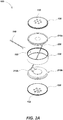
- Speaker 100 may include a speaker enclosure 110 having a pair of loudspeaker drivers within (e.g., drivers 210a and 210b illustrated in FIG. 2 ).
- the enclosure 110 may optionally be magnetically shielded with a magnetic shielding material such as tin plated mild steel or other magnetically permeable materials or shielding materials or assemblies.
- the enclosure may be made of other materials, or the audio speaker device may have no enclosure.
- Audio speaker devices may cancel magnetic fields using opposing polarities in loudspeaker drivers (e.g., north facing north or south facing south pole orientations) to prevent or reduce generation of external electromagnetic fields, and correspondingly reduce or eliminate interfering magnetic signatures.
- Cancelling of dipole fields may result in a quadrupole field, which advantageously falls off more rapidly with distance than the dipole field generated by typical loudspeakers.
- the enclosure 110 may include a housing 120 of a metallic, plastic, or other material that may be cylindrical in shape and that may seat a cap 130 comprising a metallic, plastic, or other material (one of two caps in the illustrated embodiment is obscured for view within FIG. 1 ) onto each end of the housing 120 in assembly.
- the housing 120 may be cylindrical in shape add may be formed or cut with a passage 122 allowing a twisted pair of electrical signal wires 140 to pass through.
- the wires 140 may be used to provide sound signals to drive the drivers 210a and 210b (as show in FIG. 2 ) within enclosure 110 from an external source (e.g. a utility locator 700 of FIG. 7A including an audio signal generator and amplifier to provide the electrical signal or from another audio generating device or system).
- an external source e.g. a utility locator 700 of FIG. 7A including an audio signal generator and amplifier to provide the electrical signal or from another audio generating device or system.
- Each cap 130 may be formed or cut with a series of sound hole features 132.
- the sound hole features 132 are cuts or opening to allow sound generated within enclosure 110 to propagate to the exterior (to be heard by a locator or other device user/operator), while also providing optional magnetic shielding of the enclosure 110, for example by providing a path for the magnetic fields emitted from drivers 210a and 210b and aiding in containing/attenuating magnetic fields.
- the loudspeaker driver embodiments 210a and 210b may be two of the same or similarly constructed loudspeaker driver elements having identical or similar magnetic field characteristics over a desired range of frequencies, and having the same or similar electromagnetic responses to electrical signals (e.g., over a range of frequencies that are to be attenuated to avoid magnetic field interference with other components of an associated system, such as a utility locator or other magnetic field sensing device).
- the loudspeaker drivers may be oriented with magnet components having opposing magnetic polarities to repel them from one another and cancel opposing dipole fields, thereby creating a magnetic quadrupole field.
- multiple pairs of loudspeakers may be used, wherein the pairs are arranged with opposing magnetic polarities to cancel magnetic fields.
- Other structural and topological driver relationships that interact to cancel all or part of magnetic fields in all or some particular directions may also be used in alternate embodiments.
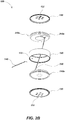
- loudspeaker driver elements 210a and 210b may be closely seated and oriented back to back, and may further be positioned about a shared axis ( e.g. axis 410 illustrated in FIG. 4A ) such as shown in audio speaker device embodiment 100.
- loudspeaker drivers 210a and 210b may be wired in parallel via wiring such as a twisted pair of wires 220 as shown.
- Another twisted pair of wires 140 may be electrically connected to each terminal on terminals 212a as is commonly done with speaker driver electrical connections.
- One wire of the twisted pair of wires 220 may further connect to each terminal on terminals 212a on one end and also connect to each terminal of terminals 212b on the other.
- the drivers 210a and 210b may be wired in parallel, with wires connecting to terminals 212b rather than 212a.
- loudspeaker drivers may be wired in series.
- one wire from a first twisted pair of wires (which may be wires 140 as shown) may connect to one terminal of each terminal set on each loudspeaker.
- each wire is connected to particular terminals of the set of terminals on each driver so that when supplied with an electrical signal, the voice coil of each loudspeaker moves outward or inward in unison ( i.e., in phase).
- an additional wire may be connected between the other terminal from each set of terminals on each loudspeaker driver not connected by the wire from the first twisted pair.
- electrical signals may be conductively coupled via twisted pair 140 from an external source (e.g . utility locator 700 of FIG. 7A configured to provide an electrical signal via an audio amplifier from a signal generator or other audio signal source - it is noted that in some embodiments, signals outside of the normal audible human sound range may be provided to drivers and in the case where these signals can cause interference at inaudible frequencies (either supersonic or subsonic) similar configurations for magnetic field cancellation may also be used).
- an external source e.g . utility locator 700 of FIG. 7A configured to provide an electrical signal via an audio amplifier from a signal generator or other audio signal source - it is noted that in some embodiments, signals outside of the normal audible human sound range may be provided to drivers and in the case where these signals can cause interference at inaudible frequencies (either supersonic or subsonic) similar configurations for magnetic field cancellation may also be used).
- Drivers 210a and 210b may seat within housing 120 with wires 220 pushed to one side or the other so that the back sides of pole components 342a and 342b illustrated in FIGs. 3A and 3B respectively are close together or directly touch.
- a toroidal groove feature 420 formed along a top and bottom inner circumference of housing 120 may be dimensioned to snugly fit a lip feature 430 formed along the circumference on the cap 130.
- the cap 130 may secure to housing 120 by seating the lip feature 430 of cap 130 into groove feature 420 of housing 120.
- Adhesives may be used to secure the loudspeaker 210a and cap 130 and/or housing 120 together.
- the cap 130 may secure to housing 120 about the loudspeaker 210 via an identical or similar groove feature 420 formed along the bottom (not illustrated) inner circumference of housing 120, allowing the lip feature 430 to seat therein.
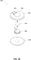
- the loudspeaker driver embodiments 210a (shown in FIG. 3A ) and 210b (shown in FIG. 3B ) may be of the same or similar type.
- the drivers may be electrodynamic drivers for converting electrical sound signals into sound waves ( i.e., motion of air or other media in which the drivers are placed).
- Each may have a corresponding magnet 310a, 310b and voice coil 320a, 320b (comprising a wire coil and optionally additional elements), respectively.
- Drivers 210a and 210b may also each have a diaphragm 330a, 330b (movable to generate air movement), and a backing components 340a, 340b, respectively.
- the magnets 310a, 310b and voice coils 320a, 320b are positioned in assembly so that when an electrical sound signal (current signal) flows in voice coils 320a, 320b, the resulting electromagnetic field therefrom interacts with the magnetic field from their respective magnets 310a, 310b, to cause either an attractive or repulsive motion corresponding to the supplied electrical signal.
- the voice coils 320a and 320b move in an analogous fashion, and, in turn, when mechanically coupled to respective diaphragms 330a and 330b produce air motion/sound.
- Other loudspeaker drivers as known or developed in the art may be used in alternate embodiments to effect conversion of electrical energy to sound by similar or equivalent magnetic field cancellation techniques as described herein.
- magnets 310a and 310b may have a permanent magnets, may be cylindrical in shape, and may adhere or otherwise secure within a cavity formed within pole components 342a and 342b of backing components 340a and 340b, respectively.
- a gap may be formed between pole components 342a, 342b and magnets 310a, 310b, with the gap dimensioned to allow respective voice coils 320a, 320b to fit within.
- FIGs 3A and 3A show details of a pair of exemplary loudspeaker driver elements in mirror image position as they may be assembled in typical embodiments.
- each voice coil 320a, 320b may be secured/mechanically coupled to their respective diaphragm 330a, 330b so that the voice coils 320a, 320b seat within the gap formed between pole components 342a, 342b, and magnets 310a, 310b in assembly.
- the voice coils 320a, 320b may be electrically connected to each terminal of their respective terminals 212a, 212b.
- other arrangements and shapes of magnets, voice coils, diaphragms, pole components, and/or other loudspeaker driver elements may be used.
- other types of speakers may be used.
- Each pole component 342a, 342b may be shaped and oriented to affect the electromagnetic field emitted from corresponding voice coils 320a, 320b.
- each pole component may be shaped and sized as shown in FIG. 3A and FIG. 3B to concentrate and direct the magnetic fields of their corresponding magnet 310a, 310b (so as to control how they interact with electromagnetic fields emitted by voice coils 320a, 320b when driven by an electrical signal).
- pole components may be of other shapes, sizes, and/or dimensions, and/or may utilize various materials.
- the pole components may be configured to further control or lessen the amount of electromagnetic fields emitted by the voice coils in particular directions; this may be used to minimize the electromagnetic signature to avoid interfere with other devices, such as utility locators.
- loudspeaker driver embodiments 210a and 210b may be positioned back to back and closely together as shown so that magnet 310a of driver 210a is oriented in polar opposition to the magnet 310b of driver 210b.
- voice coil 320a of driver 210a may be oriented in polar opposition to the voice coil 320b of driver 210b when each is supplied with an electrical signal or signals.
- the orientation of magnets 310a and 310b and voice coils 320a and 320b in polar opposition may be on a common axis 410 such that magnetic fields emitted from loudspeakers 210a and 210b cancel. Cancellation of the dipole fields in this way results in a quadrupole field 450, which advantageously falls off more rapidly with distance than the dipole field generated by typical loudspeakers.
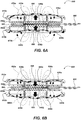
- FIG. 5A and FIG. 5B illustrate example magnetic field signatures in an exemplary paired loudspeaker driver assembly.
- Electromagnetic fields from opposite voice coils such as electromagnetic fields 510a, 510b of FIG. 5A , and 550a, 550b of FIG. 5B , emitted from voice coils 320a, 320b when energized, are largely the same in shape and magnitude, but are oriented in polar opposition such that they cancel.
- diaphragms 330a and 330b push outward in directions 520a and 520b (as shown in FIG. 5A ) or inward in directions 560a and 560b (as shown in FIG. 5B ), producing sound.
- the corresponding electromagnetic fields 510a and 510b or 550a and 550b from voice coils 320a and 320b also change in unison to maintain like opposition in polarity in magnitude and magnetic field shape.
- orientations of magnets within loudspeaker driver pairs may be varied so as to fully or partially cancel electromagnetic fields from other (e.g., oppositely position) drivers.
- the driver elements or other speaker components may be arranged so that the polarity of magnetic fields are cancelled while the diaphragms of opposing loudspeakers move in unison in a common direction, while the electromagnetic fields therefrom are fully or partially cancelled over at least a desired range of frequencies.
- an audio speaker device embodiment 600 may be similar in structure and components to the audio speaker device embodiment 100 of FIGs. 1 - 5B .
- embodiment 600 includes a pair of loudspeakers 610a, 610b each with a voice coil 620a, 620b secured to a diaphragm 630a, 630b.
- Each voice coil 620a, 620b may be positioned to interact when driven with the magnetic field of a corresponding permanent magnet 640a, 640b within a backing component 650a, 650b when a signal is driven through wiring 660 and 665.
- Each voice coil 620a, 620b when supplied with an electrical sound signal, may generate a corresponding electromagnetic field 670a, 670b (as shown in FIG. 6A ) or 680a, 680b (as shown in FIG. 6B ) causing a corresponding movement in direction 690 or 695.
- the components may be arranged so that the polarity of magnetic and electromagnetic fields (i.e., electromagnetic fields 670a, 670b in FIG. 6A and 680a, 680b in FIG. 6B ) are such that diaphragms 630a and 630b of opposing loudspeakers 610a and 610b move in unison in a common direction 690 in FIG. 6A or 695 in FIG. 6B , while the electromagnetic fields 670a and 670b in FIG. 6A or 680a and 680b in FIG. 6B therefrom cancel.
- electromagnetic fields 670a and 670b in FIG. 6A or 680a and 680b in FIG. 6B therefrom cancel.
- orientations of magnets 640a and 640b in loudspeakers 610a and 610b, respectively, are aligned to attract such that corresponding voice coils 620a and 620b move in unison in a common direction when supplied with an electrical signal.
- directions of windings or directions in which an electrical signal is driven through one voice coil may be configured to produce a geometry where polarities of voice coils and magnets allow the diaphragm of opposing loudspeakers to move in unison in a common direction.
- audio speaker device embodiments described herein have a reduced magnetic signature while providing high quality dynamic sound over a desired range of frequencies (typically within the audible human range, but in some applications over higher (ultrasonic) and/or lower (infrasonic) frequencies).
- audio speaker device embodiments in accordance with various aspects of the present disclosure may be used in various devices and systems that are used to detect or measure magnetic signals across a range of magnetic signal frequencies, particularly where providing quality dynamic sound (or ultrasound or infra-sound) to a user is needed or otherwise advantageous
- audio speaker device embodiments such as are described herein may be used with a magnetic field sensing buried utility locator device.
- exemplary utility locator embodiment 700 of FIG. 7A includes magnetic field antenna arrays 710 and 712 to receive AC magnetic field signals across a range of frequencies and provide corresponding output electrical signals corresponding to the received magnetic fields. These output electrical signals are then processed in electronic circuits, including one or more processing elements, to determine information about hidden or buried utility or other current carrying conductors (based on the magnetic fields resulting from current flow therein. Examples and details of embodiments of such antennas and signal processing are described in the incorporated applications.
- the locator may then store the determined information as well as communicate information about the buried object or utility, or about locator operation, to a user or users.
- Existing loudspeakers particularly those used in locators, normally generate electromagnetic signals at frequencies that overlap to some extent with the range of frequencies the locator is trying to sense and process.
- audio speaker devices in accordance with various aspects of the present disclosure e.g., audio speaker device 750 of FIG. 7B ) have attenuated magnetic field signatures, which may eliminate or reduce interfere with magnetic field signals received at locator antenna arrays 710 and 712.
- utility locator 700 may communicate information to a user or users through audible indicators across a range of frequencies, such as those required to reproduce human speech or other human audible sounds.
- a locator may include audio electronics to generate audio output signals based on information determined by the locator about the buried object or buried utility or other information, such as information related to operation of the locator or other devices.
- the audio electronics may be operatively coupled to or integrated in the locator electronics.
- FIG. 7B a cutaway of the rear portion of a handle 720 of utility locator 700 is shown.
- Audio speaker device 750 is seated in a vertical orientation within the handle.
- the audio speaker device 750 may be of the variety disclosed previously herein or other similar or equivalent devices, and may generate sound that travels outward, exiting through sound holes 730 ( FIG. 7A ) formed along locator handle 720.
- the audio speaker device 750 may be positioned on or within the locator so that the magnetic fields emitted therefrom minimize interference with other signals within a desired frequency range that are received at antenna arrays 710 and 712.
- FIG. 8 illustrates details of another audio speaker device embodiment.
- Audio speaker device embodiment 800 may include a speaker enclosure 810 having a pair of loudspeakers within (e.g ., loudspeaker drivers 910a and 910b illustrated in FIG. 9 , which may be similar to the other driver embodiments disclosed herein and may share similar or common components).
- the enclosure 810 may optionally be magnetically shielded with a material comprising tin plated mild steel or other magnetically permeable materials or other magnetic shielding materials and/or assemblies. Canceling of magnetic fields may be done by using opposing polarities in loudspeaker drivers to prevent or reduce generation of external electromagnetic fields, and thereby reduce or eliminate interfering magnetic field signatures.
- magnets within the drivers of embodiment 800 may be positioned so that north and north or south and south polarities face one another, thereby creating a magnetic quadrupole.
- the fields of this magnetic quadrupole advantageously fall off more rapidly with distance than a dipole field as results from typical loudspeakers.
- Enclosure 810 may include two housing components 820 that secure together with a securing band 830 that, in combination with a tape seal 950 (as shown in FIG. 9 ), seals where the two housing components 820 mate together.
- the securing band 830 may be made of rubber or other elastomeric material that may aid in holding the two housing components 820 together.
- a connector 840 may extend from within enclosure 810, allowing electrical signals from an external sound signal source (e.g., a utility locator sound generator and audio amplifier) to pass through the enclosure and to the loudspeaker drivers 910a and 910b within enclosure 810.
- Each of the housing elements 820 may be formed having a series of sound hole features 822.
- the sound hole features 822 may be included to allow sound generated within enclosure 810 to effectively travel to the exterior environment, while still allowing optional magnetic shielding of the enclosure 810 to provide a path for the magnetic fields emitted from loudspeakers 910a and 910b and aid in containing magnetic fields therein.
- FIG. 9 illustrates details of a loudspeaker drive element embodiment 900.
- Driver embodiments 910a and 910b may be two of the same or similarly constructed devices having identical or similar magnetic field characteristics over a targeted range of frequencies, and the same or similar electromagnetic responses to electrical signals.
- the loudspeaker drivers 910a and 910b may be oriented with opposing magnetic polarities such as described previously herein so as to repel each other and cancel the opposing dipole fields, resulting in a magnetic quadrupole.
- the drivers may be arranged so that the same magnetic polarity on the magnet of loudspeaker driver 910a faces that of driver 910b and they thereby repel each other.
- multiple pairs of loudspeakers drivers (or other numbers of drivers) may be used, with drivers arranged with opposing magnetic polarities to cancel magnetic fields.
- drivers 910a and 910b may be closely positioned back to back and may be aligned along a shared axis ( e.g. axis 1100) within audio speaker device 800.
- Connector 840 may be positioned along a protruding arm of a PCB that may otherwise be annular, such as PCB 940.
- PCB 940 may have a central opening shaped and dimensioned to allow the rear portion of each driver 910a and 910b containing the magnets therein (e.g., magnets 1110a and 1110b as shown in FIG. 11A ) to seat within the central opening of the PCB 940.
- Finger contacts 942 may be placed on either face of PCB 940 and may be aligned with corresponding contact 912a and 912b on loudspeaker drivers 910a and 910b, respectively.
- 912a and 912b may press into contacts 942 on their respective sides of PCB 940 to establish an electrical connection between PCB 940 and each driver 910a and 910b.
- Sealing tape 950 may secure circumferentially about the location where the two housing component 820 mate together, or they may be sealed by other sealing mechanisms such as adhesives, thermal bonding, and the like).
- the sealing tape 950 may be positioned beneath the securing band 830. It should be noted that a gap may be formed through both sealing tape 950 and securing band 830 to allow connector 840 to pass through.
- a backing ring 960 may be adhered within each of the two housing components 820.
- adhesive tape 980 or other adhesive mechanisms may retain backing ring 960 in place and allow an O-ring 970 to be seated between each of the two housing elements 820 and respective drivers 910a and 910b to seal embodiment 800 from the external environment.
- FIG. 11A is a cross-sectional view of embodiment 800. Magnets 1110a and 1110b within each respective driver 910a and 910b are shown, along with other components. As illustrated, magnets 1110a and 1110b may be positioned with like polarities facing each other. For example, the north pole of magnet 1110a may face the north pole of magnet 1110b. Each magnet 1110a and 1110b may seat within a voice coil 1120a or 1120b such that each loudspeaker driver 910a and 910b has the same response to electrical sound signals provided through connector 840 and PCB 940. Each voice coil 1120a, 1120b may be coupled to a diaphragm 1130a, 1130b to produce sound when the electrical signal is provided to the voice coils 1120a and 1120b.
- an O-ring 970 may be seated between loudspeaker 1110a and the backing ring 960 within the corresponding housing component 820, providing a seal to external elements.
- Another O-ring 970 may also be seated between loudspeaker 1110b (as shown in FIG. 11A ) and the backing ring 960 within the corresponding housing component 820.
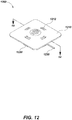
- Audio speaker device embodiments in accordance with some aspects of the present disclosure may include a sound directing enclosure to direct sound out in a single direction while providing magnetic field cancelation.
- a sound directing enclosure embodiment 1200 may include a front enclosure facing 1210 having a series of sound holes 1212 to allow passage of sound from within.
- the sound directing enclosure 1200 may also include a sound redirecting enclosure portion 1220 (largely obscured in FIG. 12 but illustrated in detail in FIG. 13 ) that may mate to the front enclosure facing 1210 in assembly.
- the sound redirecting enclosure portion 1220 may allow redirection of sound from within towards the front enclosure facing 1210.
- a wiring harness 1230 may pass between front enclosure facing 1210 and sound redirecting enclosure portion 1220 as shown.
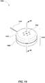
- an audio speaker device embodiment 1310 may be positioned within the sound redirecting enclosure portion 1220 and enclosed therein by the front enclosure facing 1210. Audio speaker device embodiment 1310 may be or share aspects with audio speaker device embodiment 810 of FIGs. 8 - 11B or other audio speaker device embodiment described herein.
- the wiring harness 1230 may connect to the connector on audio speaker device embodiment 1310 providing audio signals thereto.
- the wiring harness 1230 may pass through a gap 1322 on sound redirecting enclosure portion 1220.
- a seal 1332 may be secured to wiring harness 1230 to close the space in gap 1322 not occupied by wiring passing through thus providing protection from the external environment.
- An O-ring 1320 may seat within sound directing enclosure embodiment 1200 between the front enclosure facing 1210 and sound redirecting enclosure portion 1220 provide additional protection from the external environment.
- a series of screws 1340 or other attachment elements may secure the sound redirecting enclosure portion 1220 and the front enclosure facing 1210.
- sound directing enclosure embodiment 1200 directs sound out through the sound holes 1212 formed through front enclosure facing 1210.
- sound emitted from the side of the audio speaker device embodiment 1310 facing the front enclosure facing 1210 may travel along the direction 1410 and out of the device.
- Sound emitted from the side of the audio speaker device embodiment 1310 facing away the front enclosure facing 1210 may reflect off the sound redirecting enclosure portion 1220 and also be directed towards the sound holes 1212 formed through front enclosure facing 1210 along direction 1420. Sound wave distances of travel may be selected to provide constructive and/or destructive interference so as to control the frequency response of the associated speaker device or system.
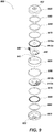
- FIG. 15 illustrates details of an audio speaker device embodiment 1500.
- Embodiment 1500 may be similar to those described previously herein and/or may share the same or similar components and assembly.
- Embodiment 1500 includes a speaker enclosure 1510 having a pair of loudspeaker drivers within (e.g., drivers 1610a and 1610b illustrated in FIG. 16 ).
- the enclosure 1510 may optionally be magnetically shielded with a material such as tin plated mild steel or other magnetically permeable materials or magnetic shielding assemblies.
- Audio speakers may cancel magnetic fields using opposing polarities in driver components to prevent or reduce generation of external electromagnetic fields and likewise reduce or eliminate an interfering magnetic field signatures over a desired frequency band of interest.
- magnets in the loudspeaker drivers may be positioned such that north and north or south and south polarities face one another, thereby creating a magnetic quadrupole.
- Enclosure 1510 may include two housing components 1520 that may be positioned back to back, forming an internal cavity for housing the loudspeaker drivers and other internal components (e.g., drivers 1610a and 1610b illustrated in FIG. 16 ).
- the two housing components 1520 may be secured together by force using an internal securing ring 1620 (as shown in further detail in FIG. 16 ) that may be press fit within the enclosure 1510.
- the internal securing ring 1620 may apply an outward force in contact with each of the two housing components 1520 to hold the enclosure 1510 together.
- Each of the housing components 1520 may be formed having a series of sound holes 1522.
- the sound holes 1522 may be formed to permit sound generated within enclosure 1510 to travel outside the enclosure to the outer environment (for a user to hear), while also allowing optional magnetic shielding of the enclosure 1510 to provide a path for the magnetic fields emitted from loudspeakers 1610a and 1610b ( FIG. 16 ) and aid in containing magnetic fields therein.
- Connecting electrical signal wires 1530 may extend outside from within enclosure 1510, allowing electrical signals from a connected device (such as audio signal generator and amplifier of a utility locator such as utility locator 700) to drive the loudspeaker drivers 1610a and 1610b ( FIG. 16 ) within enclosure 1510.
- Driver embodiments 1610a and 1610b may be two of the same or similarly constructed loudspeaker driver elements having identical or similar characteristics over a targeted range of frequencies, and may have the same or similar electromagnetic field signatures to electrical driving signals over at least the targeted frequency range. Typically the drivers are of the same type and model.
- the loudspeaker drivers may be oriented with opposing magnetic polarities so as to repel from one another and may be oriented to cancel the opposing dipole fields, thereby creating a magnetic quadrupole.
- the same magnetic polarity on driver 1610a may face that of driver 1610b so they repel each other.
- the magnetic dipole fields may cancel to generate a magnetic quadrupole field that advantageously falls off more rapidly with distance than a dipole field.
- Loudspeakers 1610a and 1610b may be closely seated back to back and be positioned about a shared axis ( e.g. axis 1800 illustrated in FIG. 18 ) within audio speaker embodiment 1500.
- Connecting wires 1530 may attach to a PCB 1630.
- the PCB 1630 may sit within a mounting cavity feature 1742 (as shown in FIG. 17 ) formed on a largely annular PCB retainer component 1640.
- the PCB retainer 1640 may have a central opening dimensioned to allow the rear portion of each driver 1610a and 1610b, which contain the magnets therein (e.g ., magnets 1810a and 1810b as shown in FIG. 18 ) to seat within a central opening of the annular PCB retainer 1640.
- the PCB retainer 1640 may include a series of evenly spaced rib features 1744 formed along its external circumference that may, in assembly, press into securing ring 1620 to ensure even distribution of press fit forces holding enclosure 1510 together.
- the PCB 1630 may include finger contacts 1732 situated on either face of PCB 1630.
- the contacts 1732 may align with contacts 1612 on each loudspeaker 1610a (obscured in FIG. 16 ) and 1610b and may press into contacts 1732 on their respective sides of PCB 1630, establishing an electrical pathway between PCB 1630 and each loudspeaker 1610a and 1610b.
- the securing ring 1620 may be press fit circumferentially within the enclosure 1510 between the PCB retainer 1640 and enclosure 1510 ( FIG. 16 ), and in place apply an outward force where contacting each of the two housing components 1520, thereby holding the enclosure 1510 together. It should be noted that a gap may be formed through securing ring 1620 to allow the passage of connecting wires 1530.
- a backing ring 1660 may be adhered within each of the two housing components 1520.
- adhesive tape 1680 may secure backing ring 1660 in place and allow an O-ring 1670 seated between each of the two housing halves 1520 and their respective loudspeakers 1610a and 1610b to seal the audio speaker device embodiment 1500 from the external environment.
- Magnets 1810a and 1810b may be positioned within each respective loudspeaker driver 1610a and 1610b as shown, with like polarities facing.
- the north pole of magnet 1810a may face the north pole of magnet 1810b.
- Each magnet 1810a and 1810b may seat within a voice coil 1820a or 1820b such that each driver 1610a and 1610b has the same response to electrical current signals provided by an external electrical signal source.
- Each voice coil 1820a and 1820b may secure to a diaphragm 1830a or 1830b to produce sound when the audio electrical signal is provided to the voice coils 1820a and 1820b.
- Skilled artisans may implement the described functionality in varying ways for each particular application, but such implementation decisions should not be interpreted as causing a departure from the scope of the present disclosure.
- embodiments of magnetic field cancelling speaker devices and/or associated utility locators or other associated devices or systems may include means for performing various functions as described herein.
- the aforementioned means may be in mechanical or electrical components as described herein and/or as shown in the Drawings.
- the means in some embodiments may include a processing element using a processor or processors and associated memory in which embodiments reside, and which are configured to perform the functions recited by the aforementioned means.
- the aforementioned means may be, for example, modules or apparatus residing in a printed circuit board element or modules, or other electronic circuitry modules, to perform the functions, methods, and processes as are described herein.
- the aforementioned means may be a module or apparatus configured to perform the functions recited by the aforementioned means.
- functions, methods, and processes described may be implemented in whole or in part in hardware, software, firmware, or any combination thereof. If implemented in software, the functions may be stored on or encoded as one or more instructions or code on a non-transitory processor-readable medium and may be executed in one or more processing elements.
- Processor-readable media includes computer storage media. Storage media may be any available non-transitory media that can be accessed by a computer, processor, or other programmable digital device.
- Such computer-readable media can include RAM, ROM, EEPROM, CD-ROM or other optical disk storage, magnetic disk storage or other magnetic storage devices, or any other medium that can be used to carry or store desired program code in the form of instructions or data structures and that can be accessed by a computer.
- Disk and disc includes compact disc (CD), laser disc, optical disc, digital versatile disc (DVD), floppy disk and Blu-ray disc where disks usually reproduce data magnetically, while discs reproduce data optically with lasers. Combinations of the above should also be included within the scope of computer-readable media.
Landscapes
- Engineering & Computer Science (AREA)
- Physics & Mathematics (AREA)
- Acoustics & Sound (AREA)
- Signal Processing (AREA)
- Remote Sensing (AREA)
- Life Sciences & Earth Sciences (AREA)
- Otolaryngology (AREA)
- Health & Medical Sciences (AREA)
- Electromagnetism (AREA)
- Environmental & Geological Engineering (AREA)
- Geology (AREA)
- General Life Sciences & Earth Sciences (AREA)
- General Physics & Mathematics (AREA)
- Geophysics (AREA)
- Audible-Bandwidth Dynamoelectric Transducers Other Than Pickups (AREA)
Claims (16)
- Système de localisation de services publics enterrés, comprenant :
un dispositif de localisation de services publics enterrés (700), comprenant :un boîtier ;un réseau d'antennes à champ magnétique (710, 712) disposé sur ou dans le boîtier pour recevoir des signaux de champ magnétique émis par un conducteur caché ou enterré sur la base d'un flux de courant dans celui-ci et fournir des signaux de sortie électriques correspondants ; etun circuit électronique de localisation de services publics disposé sur ou dans le boîtier et couplé de manière fonctionnelle à la sortie de réseau d'antennes à champ magnétique pour recevoir les signaux de sortie électriques et générer des informations concernant le conducteur caché ou enterré ;un générateur de signal audio et un amplificateur audio couplés de manière fonctionnelle au circuit électronique de localisation de services publics pour générer et fournir un signal de sortie audio associé au fonctionnement du dispositif de localisation de services publics ; etun dispositif de haut-parleur audio (100, 600, 800, 1310, 1500), comprenant :une enceinte de haut-parleur (110, 810, 1510) ;un câblage d'entrée couplé de manière fonctionnelle au signal de sortie audio ;un premier circuit d'attaque de haut-parleur (210a, 610a, 910a, 1610a) ayant des bornes couplées de manière fonctionnelle au câblage d'entrée pour recevoir le signal de sortie audio avec une première polarité ; etun second circuit d'attaque de haut-parleur (210b, 610b, 910b, 1610b), du même type que le premier circuit d'attaque de haut-parleur, ayant des bornes couplées de manière fonctionnelle au câblage d'entrée pour recevoir le signal de sortie audio avec une seconde polarité ;le premier circuit d'attaque de haut-parleur et le second circuit d'attaque de haut-parleur étant positionnés à l'intérieur de l'enceinte de haut-parleur de manière à annuler au moins partiellement les signaux de champ magnétique de courant alternatif (CA) émis par celui-ci sur une fréquence ou une plage de fréquences prédéfinie chevauchant la fréquence ou la plage de fréquences émise par le conducteur caché ou enterré. - Système de localisation de services publics enterrés selon la revendication 1, le dispositif de haut-parleur audio (100, 600, 800, 1310, 1500), le générateur de signaux audio et l'amplificateur audio étant disposés sur ou dans le boîtier de localisation de services publics enterrés.
- Système de localisation de services publics enterrés selon la revendication 1, un ou plusieurs du dispositif de haut-parleur audio (100, 600, 800, 1500), du générateur de signal audio et de l'amplificateur audio étant séparés du boîtier de localisation de services publics enterrés.
- Système de localisation de services publics enterrés selon la revendication 1, la première polarité et la seconde polarité étant soit la même polarité, soit des polarités opposées.
- Système de localisation de services publics enterrés selon la revendication 1, le premier circuit d'attaque de haut-parleur (210a, 610a, 910a, 1610a) ayant un premier aimant (310a, 1110a, 1810a) et le second circuit d'attaque de haut-parleur (210b, 610b, 910b, 1610b) ayant un second aimant correspondant (310b, 1110b, 1810b), et le premier circuit d'attaque de haut-parleur étant positionné à proximité immédiate du second circuit d'attaque de haut-parleur, soit de manière à ce que les polarités du premier aimant et du second aimant soient identiques, soit de manière à ce que les polarités du premier aimant et du second aimant soient opposées.
- Système de localisation de services publics enterrés selon la revendication 1, le premier circuit d'attaque de haut-parleur (210a, 610a, 910a, 1610a) ayant une première bobine acoustique (320a, 620a, 1120a, 1820a) et le second circuit d'attaque de haut-parleur (210b, 610b, 910b, 1610b, 1820b) ayant une seconde bobine acoustique correspondante (320b, 620b, 1120b), et la première bobine acoustique de haut-parleur et la seconde bobine acoustique de haut-parleur étant positionnées, soit de manière à ce que la première bobine acoustique de haut-parleur et la seconde bobine acoustique de haut-parleur aient des polarités opposées, soit de manière à ce que la première bobine acoustique de haut-parleur et la seconde bobine acoustique de haut-parleur aient la même polarité.
- Système de localisation de services publics enterrés selon la revendication 1, l'enceinte de haut-parleur (110, 810, 1510) étant blindée magnétiquement avec un matériau magnétiquement perméable, éventuellement, le matériau magnétiquement perméable étant de l'acier doux étamé.
- Système de localisation de services publics enterrés selon la revendication 1, l'enceinte de haut-parleur (110, 810, 1510) étant de forme cylindrique et comprenant un passage avec une paire torsadée traversant celui-ci, éventuellement, le dispositif de localisation comprenant en outre une paire de capuchons ayant des caractéristiques de trou sonore positionnés dans le boîtier.
- Système de localisation de services publics enterrés selon la revendication 1, le boîtier comprenant une rainure toroïdale (420), les capuchons comprenant une caractéristique de lèvres (430) et les lèvres étant positionnées en contact étroit avec la rainure toroïdale.
- Système de localisation de services publics enterrés selon la revendication 1, les circuits d'attaque de haut-parleur étant positionnés autour d'un axe longitudinal commun.
- Système de localisation de services publics enterrés selon la revendication 1, comprenant en outre une poignée de localisation (720), le dispositif de haut-parleur audio étant disposé dans, sur ou à l'intérieur de la poignée.
- Système de localisation de services publics enterrés selon la revendication 1, le dispositif de haut-parleur audio contenant un PCB (940, 1630) ayant des contacts à ressort qui pressent dans des contacts correspondants sur les circuits d'attaque de haut-parleur, établissant des trajets électriques pour communiquer des signaux sonores électriques à ceux-ci.
- Système de localisation de services publics enterrés selon la revendication 1, comprenant un PCB de forme annulaire dimensionnée pour recevoir la partie arrière de chaque circuit d'attaque de haut-parleur dans celui-ci.
- Système de localisation de services publics enterrés selon la revendication 1, le dispositif de haut-parleur audio comprenant une enceinte pour diriger le son à partir des deux circuits d'attaque de haut-parleur dans une direction commune.
- Système de localisation de services publics enterrés selon la revendication 1, les circuits d'attaque de haut-parleur comprenant chacun des composants polaires (342a, 342b) ayant des trous dans ceux-ci pour former un champ magnétique, et des aimants de chacun des circuits d'attaque de haut-parleur étant positionnés au moins partiellement à l'intérieur des trous pour former le champ magnétique afin de réduire des interférences avec les antennes de localisation.
- Système de localisation de services publics enterrée selon la revendication 1, comprenant en outre une enceinte avant placée à proximité immédiate d'un premier des circuits d'attaque de haut-parleur et ayant un ou plusieurs trous sonores, et une partie de réorientation de son pour rediriger des ondes sonores incidentes à partir de l'autre des circuits d'attaque de haut-parleur vers la face avant et les trous sonores.
Applications Claiming Priority (2)
| Application Number | Priority Date | Filing Date | Title |
|---|---|---|---|
| US201762445711P | 2017-01-12 | 2017-01-12 | |
| PCT/US2018/013669 WO2018132772A1 (fr) | 2017-01-12 | 2018-01-12 | Haut-parleurs audio d'annulation de champ magnétique destinés à être utilisés avec des dispositifs de localisation de services publics enterrés ou d'autres dispositifs |
Publications (2)
| Publication Number | Publication Date |
|---|---|
| EP3568996A1 EP3568996A1 (fr) | 2019-11-20 |
| EP3568996B1 true EP3568996B1 (fr) | 2021-05-12 |
Family
ID=61224500
Family Applications (1)
| Application Number | Title | Priority Date | Filing Date |
|---|---|---|---|
| EP18705196.6A Active EP3568996B1 (fr) | 2017-01-12 | 2018-01-12 | Haut-parleurs audio d'annulation de champ magnétique destinés à être utilisés avec des dispositifs de localisation de services publics enterrés ou d'autres dispositifs |
Country Status (3)
| Country | Link |
|---|---|
| US (4) | US10555086B2 (fr) |
| EP (1) | EP3568996B1 (fr) |
| WO (1) | WO2018132772A1 (fr) |
Families Citing this family (31)
| Publication number | Priority date | Publication date | Assignee | Title |
|---|---|---|---|---|
| EP3555704B1 (fr) | 2016-12-15 | 2024-04-17 | Milwaukee Electric Tool Corporation | Dispositif d'inspection de canalisation |
| EP3568996B1 (fr) * | 2017-01-12 | 2021-05-12 | SeeScan, Inc. | Haut-parleurs audio d'annulation de champ magnétique destinés à être utilisés avec des dispositifs de localisation de services publics enterrés ou d'autres dispositifs |
| CN217543532U (zh) | 2018-05-09 | 2022-10-04 | 米沃奇电动工具公司 | 管线检查装置和管线检查系统 |
| US20200020330A1 (en) * | 2018-07-16 | 2020-01-16 | Qualcomm Incorporated | Detecting voice-based attacks against smart speakers |
| EP3948363B1 (fr) | 2019-03-27 | 2024-04-24 | SeeScan, Inc. | Traitement de signal à haute performance et à faible coût dans un système de localisation de réseau de service public enterré par détection de champ magnétique |
| USD988113S1 (en) | 2019-05-09 | 2023-06-06 | Milwaukee Electric Tool Corporation | Receptacle for pipeline inspection device |
| USD983469S1 (en) | 2019-05-09 | 2023-04-11 | Milwaukee Electric Tool Corporation | Hub for pipeline inspection device |
| US11243278B2 (en) | 2019-07-03 | 2022-02-08 | SeeScan, Inc. | Auto-tuning circuit apparatus and methods |
| AU2020350921B2 (en) | 2019-09-19 | 2023-05-25 | Shenzhen Shokz Co., Ltd. | Acoustic output apparatus |
| WO2021163241A1 (fr) | 2020-02-12 | 2021-08-19 | Milwaukee Electric Tool Corporation | Dispositif d'examen de pipeline à commande d'image améliorée |
| WO2022020497A2 (fr) | 2020-07-22 | 2022-01-27 | Seescan, Inc | Localisation d'installation embarquée à l'aide de composants principaux |
| EP4218257A1 (fr) * | 2020-09-25 | 2023-08-02 | Apple Inc. | Système à double haut-parleur |
| CN112468941A (zh) * | 2020-11-30 | 2021-03-09 | 瑞声新能源发展(常州)有限公司科教城分公司 | 发声装置 |
| EP4359821A1 (fr) | 2021-06-20 | 2024-05-01 | SeeScan, Inc. | Télémètres laser multi-spectral visibles à la lumière du jour et systèmes et procédés associés |
| WO2023010044A1 (fr) | 2021-07-30 | 2023-02-02 | SeeScan, Inc. | Tambour de stockage de câble avec face de tambour inclinée vers l'intérieur pour système de caméra d'inspection de tuyau |
| US12360251B2 (en) | 2021-09-07 | 2025-07-15 | SeeScan, Inc. | GNSS positioning methods and devices using PPP-RTK, RTK, SSR, or like correction data |
| US20230176244A1 (en) | 2021-09-27 | 2023-06-08 | SeeScan, Inc. | Systems and methods for determining and distinguishing buried objects using artificial intelligence |
| EP4452562A1 (fr) | 2021-12-26 | 2024-10-30 | SeeScan, Inc. | Dispositifs de batterie modulaires interchangeables, appareil et systèmes |
| EP4473346A1 (fr) | 2022-02-02 | 2024-12-11 | SeeScan, Inc. | Systèmes et procédés de localisation d'utilité avec ajustement de filtre aux fluctuations du réseau électrique |
| EP4558847A1 (fr) | 2022-07-19 | 2025-05-28 | SeeScan, Inc. | Système d'annotation d'actif d'utilité vocale naturelle |
| US12363251B2 (en) | 2022-08-08 | 2025-07-15 | SeeScan, Inc. | Systems and methods for inspection animation |
| US20240167608A1 (en) | 2022-10-20 | 2024-05-23 | SeeScan, Inc. | Linked cable-handling and cable-storage drum devices and systems for the coordinated movement of a push-cable |
| US12510376B2 (en) | 2022-12-23 | 2025-12-30 | SeeScan, Inc. | Systems, apparatus, and methods for documenting utility potholes and associated utility lines |
| WO2024263640A1 (fr) | 2023-06-23 | 2024-12-26 | SeeScan, Inc. | Module de tambour interne avec interface de câble de poussée pour inspection de tuyau |
| WO2025010201A1 (fr) | 2023-07-02 | 2025-01-09 | SeeScan, Inc. | Procédés de filtrage et dispositifs de localisation de fournisseurs associés pour localiser et cartographier des lignes de fournisseurs enterrées |
| US20250028073A1 (en) | 2023-07-17 | 2025-01-23 | SeeScan, Inc. | Smartphone mounting apparatus and imaging methods for asset tagging and utilty mapping as used with utility locator devices |
| WO2025235358A1 (fr) | 2024-05-07 | 2025-11-13 | SeeScan, Inc. | Systèmes et procédés de localisation et de cartographie d'objets de services publiques enfouis utilisant l'intelligence artificielle avec traitement local ou à distance |
| US20250383220A1 (en) | 2024-06-13 | 2025-12-18 | SeeScan, Inc. | Vehicle-mounting devices and methods for use in vehicle-based locating systems |
| US20260029094A1 (en) | 2024-07-23 | 2026-01-29 | SeeScan, Inc. | Pipe mapping for feature and asset recognition using artificial intelligence |
| WO2026055705A2 (fr) | 2024-09-09 | 2026-03-12 | SeeScan, Inc. | Modules électroniques et systèmes associés |
| WO2026059992A1 (fr) | 2024-09-12 | 2026-03-19 | SeeScan, Inc. | Procédés et appareil de permutation de batterie dans des dispositifs localisateurs de services publics et autres dispositifs électroniques à démarrage complexe |
Family Cites Families (46)
| Publication number | Priority date | Publication date | Assignee | Title |
|---|---|---|---|---|
| US1808149A (en) * | 1929-04-03 | 1931-06-02 | Smith Morris | Electrodynamic speaker |
| US2626221A (en) | 1948-02-26 | 1953-01-20 | Reed Roller Bit Co | Process of applying hard surfacing material to metal bodies |
| US2926221A (en) * | 1957-11-21 | 1960-02-23 | William A Kagdis | Loudspeaker construction |
| US4016953A (en) * | 1975-05-23 | 1977-04-12 | Butler Robert J | Push-pull transducer system |
| JP2673002B2 (ja) | 1989-03-31 | 1997-11-05 | 株式会社ケンウッド | スピーカシステム |
| US7619516B2 (en) | 2002-10-09 | 2009-11-17 | Seektech, Inc. | Single and multi-trace omnidirectional sonde and line locators and transmitter used therewith |
| US20040070535A1 (en) | 2002-10-09 | 2004-04-15 | Olsson Mark S. | Single and multi-trace omnidirectional sonde and line locators and transmitter used therewith |
| US7332901B2 (en) | 2005-04-15 | 2008-02-19 | Seektech, Inc. | Locator with apparent depth indication |
| US7009399B2 (en) | 2002-10-09 | 2006-03-07 | Deepsea Power & Light | Omnidirectional sonde and line locator |
| US7336078B1 (en) | 2003-10-04 | 2008-02-26 | Seektech, Inc. | Multi-sensor mapping omnidirectional sonde and line locators |
| US7443154B1 (en) | 2003-10-04 | 2008-10-28 | Seektech, Inc. | Multi-sensor mapping omnidirectional sonde and line locator |
| US8635043B1 (en) | 2003-10-04 | 2014-01-21 | SeeScan, Inc. | Locator and transmitter calibration system |
| JP3963173B2 (ja) * | 2004-01-06 | 2007-08-22 | ソニー株式会社 | スピーカ |
| US7221136B2 (en) | 2004-07-08 | 2007-05-22 | Seektech, Inc. | Sondes for locating underground pipes and conduits |
| US7136765B2 (en) | 2005-02-09 | 2006-11-14 | Deepsea Power & Light, Inc. | Buried object locating and tracing method and system employing principal components analysis for blind signal detection |
| US7288929B2 (en) | 2005-07-19 | 2007-10-30 | Seektech, Inc. | Inductive clamp for applying signal to buried utilities |
| US7276910B2 (en) | 2005-07-19 | 2007-10-02 | Seektech, Inc. | Compact self-tuned electrical resonator for buried object locator applications |
| US7940950B2 (en) * | 2005-10-03 | 2011-05-10 | Youngtack Shim | Electromagnetically-shielded speaker systems and methods |
| US8203343B1 (en) | 2005-10-12 | 2012-06-19 | Seektech, Inc. | Reconfigurable portable locator employing multiple sensor array having flexible nested orthogonal antennas |
| US7755360B1 (en) | 2005-10-24 | 2010-07-13 | Seektech, Inc. | Portable locator system with jamming reduction |
| US7557559B1 (en) | 2006-06-19 | 2009-07-07 | Seektech, Inc. | Compact line illuminator for locating buried pipes and cables |
| US8264226B1 (en) | 2006-07-06 | 2012-09-11 | Seektech, Inc. | System and method for locating buried pipes and cables with a man portable locator and a transmitter in a mesh network |
| US20100272885A1 (en) | 2006-08-16 | 2010-10-28 | SeekTech, Inc., a California corporation | Marking Paint Applicator for Portable Locator |
| US7741848B1 (en) | 2006-09-18 | 2010-06-22 | Seektech, Inc. | Adaptive multichannel locator system for multiple proximity detection |
| US8547428B1 (en) | 2006-11-02 | 2013-10-01 | SeeScan, Inc. | Pipe mapping system |
| US8013610B1 (en) | 2006-12-21 | 2011-09-06 | Seektech, Inc. | High-Q self tuning locating transmitter |
| US8400154B1 (en) | 2008-02-08 | 2013-03-19 | Seektech, Inc. | Locator antenna with conductive bobbin |
| US7969151B2 (en) | 2008-02-08 | 2011-06-28 | Seektech, Inc. | Pre-amplifier and mixer circuitry for a locator antenna |
| US9465129B1 (en) | 2009-03-06 | 2016-10-11 | See Scan, Inc. | Image-based mapping locating system |
| US9625602B2 (en) | 2009-11-09 | 2017-04-18 | SeeScan, Inc. | Smart personal communication devices as user interfaces |
| US9057754B2 (en) | 2010-03-04 | 2015-06-16 | SeeScan, Inc. | Economical magnetic locator apparatus and method |
| US9081109B1 (en) | 2010-06-15 | 2015-07-14 | See Scan, Inc. | Ground-tracking devices for use with a mapping locator |
| WO2013022978A2 (fr) | 2011-08-08 | 2013-02-14 | Mark Olsson | Poignées de rétroaction directionnelles haptiques pour des dispositifs de localisation |
| EP2742367B1 (fr) | 2011-08-08 | 2021-05-05 | SeeScan, Inc. | Système détecteur d'objet enterré synchronisé en phase et procédé associé |
| US9638824B2 (en) | 2011-11-14 | 2017-05-02 | SeeScan, Inc. | Quad-gradient coils for use in locating systems |
| US9341740B1 (en) | 2012-02-13 | 2016-05-17 | See Scan, Inc. | Optical ground tracking apparatus, systems, and methods |
| EP2828689B1 (fr) | 2012-03-23 | 2020-12-16 | SeeScan, Inc. | Bobines et réseaux d'antennes de gradient pour utilisation dans des systèmes de localisation |
| US9411067B2 (en) | 2012-03-26 | 2016-08-09 | SeeScan, Inc. | Ground-tracking systems and apparatus |
| US9191746B2 (en) * | 2012-08-24 | 2015-11-17 | Cheng Yih Jenq | Loudspeaker driver with dual electromagnet assemblies |
| US9599740B2 (en) | 2012-09-10 | 2017-03-21 | SeeScan, Inc. | User interfaces for utility locators |
| WO2014061092A1 (fr) * | 2012-10-16 | 2014-04-24 | TANAKA Kennta | Dispositif écouteur |
| US9798033B2 (en) | 2013-03-15 | 2017-10-24 | SeeScan, Inc. | Sonde devices including a sectional ferrite core |
| US9632199B2 (en) | 2013-07-29 | 2017-04-25 | SeeScan, Inc. | Inductive clamp devices, systems, and methods |
| US9167350B2 (en) * | 2013-11-15 | 2015-10-20 | Merry Electronics (Suzhou) Co., Ltd. | Magnetic circuit and coaxial speaker using the same |
| US9599499B1 (en) | 2015-12-21 | 2017-03-21 | International Business Machines Corporation | Linepack delay measurement in fluid delivery pipeline |
| EP3568996B1 (fr) * | 2017-01-12 | 2021-05-12 | SeeScan, Inc. | Haut-parleurs audio d'annulation de champ magnétique destinés à être utilisés avec des dispositifs de localisation de services publics enterrés ou d'autres dispositifs |
-
2018
- 2018-01-12 EP EP18705196.6A patent/EP3568996B1/fr active Active
- 2018-01-12 US US15/870,787 patent/US10555086B2/en active Active
- 2018-01-12 WO PCT/US2018/013669 patent/WO2018132772A1/fr not_active Ceased
-
2020
- 2020-01-27 US US16/773,952 patent/US11146892B1/en active Active
-
2021
- 2021-10-04 US US17/493,824 patent/US11641553B1/en active Active
-
2023
- 2023-04-17 US US18/135,677 patent/US12464292B1/en active Active
Non-Patent Citations (1)
| Title |
|---|
| None * |
Also Published As
| Publication number | Publication date |
|---|---|
| US12464292B1 (en) | 2025-11-04 |
| US11146892B1 (en) | 2021-10-12 |
| EP3568996A1 (fr) | 2019-11-20 |
| WO2018132772A1 (fr) | 2018-07-19 |
| US10555086B2 (en) | 2020-02-04 |
| US20190028812A1 (en) | 2019-01-24 |
| US11641553B1 (en) | 2023-05-02 |
Similar Documents
| Publication | Publication Date | Title |
|---|---|---|
| EP3568996B1 (fr) | Haut-parleurs audio d'annulation de champ magnétique destinés à être utilisés avec des dispositifs de localisation de services publics enterrés ou d'autres dispositifs | |
| US12262193B2 (en) | Audio source spatialization relative to orientation sensor and output | |
| US9473841B2 (en) | Acoustic source separation | |
| US10928538B1 (en) | Keyed current signal utility locating systems and methods | |
| US8085969B2 (en) | Full range planar magnetic microphone and arrays thereof | |
| JP4128144B2 (ja) | 円筒形超音波トランシーバ | |
| US20050270906A1 (en) | Resonator device and circuits for 3-d detection/receiving sonic waves, even of a very low amplitude/frequency, suitable for use in cybernetics | |
| EP3809726B1 (fr) | Estimation d'espace basée sur l'écho | |
| WO2003022156A1 (fr) | Recepteurs et emetteurs a ultrasons cylindriques constitues d'une couche mince piezo-electrique | |
| EP4042181A1 (fr) | Détecteur à ultrasons | |
| KR20100137770A (ko) | 자기 변형 트랜스듀서, 이를 이용한 구조 진단 장치 및 구조 진단 방법 | |
| Wajid et al. | Design and analysis of air acoustic vector-sensor configurations for two-dimensional geometry | |
| US20210351814A1 (en) | Devices, Systems and Methods Using a Common Frame of Reference to Provide a Consistent Magnetic Field Orientation for Magnetic Coupling | |
| US9841517B2 (en) | Wireless seismic system with phased antenna array | |
| US11582559B2 (en) | Segmented stator plates for electrostatic transducers | |
| Zaunschirm et al. | Measurement-based modal beamforming using planar circular microphone arrays | |
| EP1423051A1 (fr) | Recepteurs et emetteurs a ultrasons cylindriques constitues d'une couche mince piezo-electrique | |
| Dey et al. | Microphone array principles | |
| Simonsson | Cost-effective spatial decomposition method solution for impulse response capture and auralization | |
| CN118175472A (zh) | 多声源麦克风指向性测量方法和装置 | |
| Prajapati et al. | Study of SNR Improvement of an Equivalent Pressure Signal Obtained from an Inertial Type Acoustic Vector Sensor | |
| WO2025234884A1 (fr) | Formation de faisceau modulée | |
| Caulk | Experimental and theoretical performance of a particle velocity vector sensor in a hybrid acoustic beamformer | |
| Kwon et al. | An investigation of the performance of a ribbon and small planar magnetic transducer, made for use in air, as an underwater acoustic velocity sensor |
Legal Events
| Date | Code | Title | Description |
|---|---|---|---|
| STAA | Information on the status of an ep patent application or granted ep patent |
Free format text: STATUS: UNKNOWN |
|
| STAA | Information on the status of an ep patent application or granted ep patent |
Free format text: STATUS: THE INTERNATIONAL PUBLICATION HAS BEEN MADE |
|
| PUAI | Public reference made under article 153(3) epc to a published international application that has entered the european phase |
Free format text: ORIGINAL CODE: 0009012 |
|
| STAA | Information on the status of an ep patent application or granted ep patent |
Free format text: STATUS: REQUEST FOR EXAMINATION WAS MADE |
|
| 17P | Request for examination filed |
Effective date: 20190808 |
|
| AK | Designated contracting states |
Kind code of ref document: A1 Designated state(s): AL AT BE BG CH CY CZ DE DK EE ES FI FR GB GR HR HU IE IS IT LI LT LU LV MC MK MT NL NO PL PT RO RS SE SI SK SM TR |
|
| AX | Request for extension of the european patent |
Extension state: BA ME |
|
| DAV | Request for validation of the european patent (deleted) | ||
| DAX | Request for extension of the european patent (deleted) | ||
| GRAP | Despatch of communication of intention to grant a patent |
Free format text: ORIGINAL CODE: EPIDOSNIGR1 |
|
| STAA | Information on the status of an ep patent application or granted ep patent |
Free format text: STATUS: GRANT OF PATENT IS INTENDED |
|
| INTG | Intention to grant announced |
Effective date: 20200714 |
|
| GRAJ | Information related to disapproval of communication of intention to grant by the applicant or resumption of examination proceedings by the epo deleted |
Free format text: ORIGINAL CODE: EPIDOSDIGR1 |
|
| STAA | Information on the status of an ep patent application or granted ep patent |
Free format text: STATUS: REQUEST FOR EXAMINATION WAS MADE |
|
| RAP1 | Party data changed (applicant data changed or rights of an application transferred) |
Owner name: SEESCAN, INC. |
|
| RIN1 | Information on inventor provided before grant (corrected) |
Inventor name: MEREWETHER, RAY Inventor name: OLSSON, MARK S. |
|
| GRAP | Despatch of communication of intention to grant a patent |
Free format text: ORIGINAL CODE: EPIDOSNIGR1 |
|
| STAA | Information on the status of an ep patent application or granted ep patent |
Free format text: STATUS: GRANT OF PATENT IS INTENDED |
|
| INTC | Intention to grant announced (deleted) | ||
| INTG | Intention to grant announced |
Effective date: 20201216 |
|
| GRAS | Grant fee paid |
Free format text: ORIGINAL CODE: EPIDOSNIGR3 |
|
| GRAA | (expected) grant |
Free format text: ORIGINAL CODE: 0009210 |
|
| STAA | Information on the status of an ep patent application or granted ep patent |
Free format text: STATUS: THE PATENT HAS BEEN GRANTED |
|
| AK | Designated contracting states |
Kind code of ref document: B1 Designated state(s): AL AT BE BG CH CY CZ DE DK EE ES FI FR GB GR HR HU IE IS IT LI LT LU LV MC MK MT NL NO PL PT RO RS SE SI SK SM TR |
|
| REG | Reference to a national code |
Ref country code: GB Ref legal event code: FG4D |
|
| REG | Reference to a national code |
Ref country code: CH Ref legal event code: EP |
|
| REG | Reference to a national code |
Ref country code: DE Ref legal event code: R096 Ref document number: 602018017008 Country of ref document: DE |
|
| REG | Reference to a national code |
Ref country code: IE Ref legal event code: FG4D |
|
| REG | Reference to a national code |
Ref country code: AT Ref legal event code: REF Ref document number: 1392987 Country of ref document: AT Kind code of ref document: T Effective date: 20210615 |
|
| REG | Reference to a national code |
Ref country code: LT Ref legal event code: MG9D |
|
| REG | Reference to a national code |
Ref country code: AT Ref legal event code: MK05 Ref document number: 1392987 Country of ref document: AT Kind code of ref document: T Effective date: 20210512 |
|
| REG | Reference to a national code |
Ref country code: NL Ref legal event code: MP Effective date: 20210512 |
|
| PG25 | Lapsed in a contracting state [announced via postgrant information from national office to epo] |
Ref country code: FI Free format text: LAPSE BECAUSE OF FAILURE TO SUBMIT A TRANSLATION OF THE DESCRIPTION OR TO PAY THE FEE WITHIN THE PRESCRIBED TIME-LIMIT Effective date: 20210512 Ref country code: HR Free format text: LAPSE BECAUSE OF FAILURE TO SUBMIT A TRANSLATION OF THE DESCRIPTION OR TO PAY THE FEE WITHIN THE PRESCRIBED TIME-LIMIT Effective date: 20210512 Ref country code: LT Free format text: LAPSE BECAUSE OF FAILURE TO SUBMIT A TRANSLATION OF THE DESCRIPTION OR TO PAY THE FEE WITHIN THE PRESCRIBED TIME-LIMIT Effective date: 20210512 Ref country code: BG Free format text: LAPSE BECAUSE OF FAILURE TO SUBMIT A TRANSLATION OF THE DESCRIPTION OR TO PAY THE FEE WITHIN THE PRESCRIBED TIME-LIMIT Effective date: 20210812 Ref country code: AT Free format text: LAPSE BECAUSE OF FAILURE TO SUBMIT A TRANSLATION OF THE DESCRIPTION OR TO PAY THE FEE WITHIN THE PRESCRIBED TIME-LIMIT Effective date: 20210512 |
|
| PG25 | Lapsed in a contracting state [announced via postgrant information from national office to epo] |
Ref country code: GR Free format text: LAPSE BECAUSE OF FAILURE TO SUBMIT A TRANSLATION OF THE DESCRIPTION OR TO PAY THE FEE WITHIN THE PRESCRIBED TIME-LIMIT Effective date: 20210813 Ref country code: IS Free format text: LAPSE BECAUSE OF FAILURE TO SUBMIT A TRANSLATION OF THE DESCRIPTION OR TO PAY THE FEE WITHIN THE PRESCRIBED TIME-LIMIT Effective date: 20210912 Ref country code: PL Free format text: LAPSE BECAUSE OF FAILURE TO SUBMIT A TRANSLATION OF THE DESCRIPTION OR TO PAY THE FEE WITHIN THE PRESCRIBED TIME-LIMIT Effective date: 20210512 Ref country code: PT Free format text: LAPSE BECAUSE OF FAILURE TO SUBMIT A TRANSLATION OF THE DESCRIPTION OR TO PAY THE FEE WITHIN THE PRESCRIBED TIME-LIMIT Effective date: 20210913 Ref country code: LV Free format text: LAPSE BECAUSE OF FAILURE TO SUBMIT A TRANSLATION OF THE DESCRIPTION OR TO PAY THE FEE WITHIN THE PRESCRIBED TIME-LIMIT Effective date: 20210512 Ref country code: NO Free format text: LAPSE BECAUSE OF FAILURE TO SUBMIT A TRANSLATION OF THE DESCRIPTION OR TO PAY THE FEE WITHIN THE PRESCRIBED TIME-LIMIT Effective date: 20210812 Ref country code: RS Free format text: LAPSE BECAUSE OF FAILURE TO SUBMIT A TRANSLATION OF THE DESCRIPTION OR TO PAY THE FEE WITHIN THE PRESCRIBED TIME-LIMIT Effective date: 20210512 Ref country code: SE Free format text: LAPSE BECAUSE OF FAILURE TO SUBMIT A TRANSLATION OF THE DESCRIPTION OR TO PAY THE FEE WITHIN THE PRESCRIBED TIME-LIMIT Effective date: 20210512 |
|
| PG25 | Lapsed in a contracting state [announced via postgrant information from national office to epo] |
Ref country code: NL Free format text: LAPSE BECAUSE OF FAILURE TO SUBMIT A TRANSLATION OF THE DESCRIPTION OR TO PAY THE FEE WITHIN THE PRESCRIBED TIME-LIMIT Effective date: 20210512 |
|
| PG25 | Lapsed in a contracting state [announced via postgrant information from national office to epo] |
Ref country code: SM Free format text: LAPSE BECAUSE OF FAILURE TO SUBMIT A TRANSLATION OF THE DESCRIPTION OR TO PAY THE FEE WITHIN THE PRESCRIBED TIME-LIMIT Effective date: 20210512 Ref country code: SK Free format text: LAPSE BECAUSE OF FAILURE TO SUBMIT A TRANSLATION OF THE DESCRIPTION OR TO PAY THE FEE WITHIN THE PRESCRIBED TIME-LIMIT Effective date: 20210512 Ref country code: EE Free format text: LAPSE BECAUSE OF FAILURE TO SUBMIT A TRANSLATION OF THE DESCRIPTION OR TO PAY THE FEE WITHIN THE PRESCRIBED TIME-LIMIT Effective date: 20210512 Ref country code: ES Free format text: LAPSE BECAUSE OF FAILURE TO SUBMIT A TRANSLATION OF THE DESCRIPTION OR TO PAY THE FEE WITHIN THE PRESCRIBED TIME-LIMIT Effective date: 20210512 Ref country code: RO Free format text: LAPSE BECAUSE OF FAILURE TO SUBMIT A TRANSLATION OF THE DESCRIPTION OR TO PAY THE FEE WITHIN THE PRESCRIBED TIME-LIMIT Effective date: 20210512 Ref country code: DK Free format text: LAPSE BECAUSE OF FAILURE TO SUBMIT A TRANSLATION OF THE DESCRIPTION OR TO PAY THE FEE WITHIN THE PRESCRIBED TIME-LIMIT Effective date: 20210512 Ref country code: CZ Free format text: LAPSE BECAUSE OF FAILURE TO SUBMIT A TRANSLATION OF THE DESCRIPTION OR TO PAY THE FEE WITHIN THE PRESCRIBED TIME-LIMIT Effective date: 20210512 |
|
| REG | Reference to a national code |
Ref country code: DE Ref legal event code: R097 Ref document number: 602018017008 Country of ref document: DE |
|
| PLBE | No opposition filed within time limit |
Free format text: ORIGINAL CODE: 0009261 |
|
| STAA | Information on the status of an ep patent application or granted ep patent |
Free format text: STATUS: NO OPPOSITION FILED WITHIN TIME LIMIT |
|
| 26N | No opposition filed |
Effective date: 20220215 |
|
| PG25 | Lapsed in a contracting state [announced via postgrant information from national office to epo] |
Ref country code: IS Free format text: LAPSE BECAUSE OF FAILURE TO SUBMIT A TRANSLATION OF THE DESCRIPTION OR TO PAY THE FEE WITHIN THE PRESCRIBED TIME-LIMIT Effective date: 20210912 Ref country code: AL Free format text: LAPSE BECAUSE OF FAILURE TO SUBMIT A TRANSLATION OF THE DESCRIPTION OR TO PAY THE FEE WITHIN THE PRESCRIBED TIME-LIMIT Effective date: 20210512 |
|
| PG25 | Lapsed in a contracting state [announced via postgrant information from national office to epo] |
Ref country code: IT Free format text: LAPSE BECAUSE OF FAILURE TO SUBMIT A TRANSLATION OF THE DESCRIPTION OR TO PAY THE FEE WITHIN THE PRESCRIBED TIME-LIMIT Effective date: 20210512 |
|
| PG25 | Lapsed in a contracting state [announced via postgrant information from national office to epo] |
Ref country code: MC Free format text: LAPSE BECAUSE OF FAILURE TO SUBMIT A TRANSLATION OF THE DESCRIPTION OR TO PAY THE FEE WITHIN THE PRESCRIBED TIME-LIMIT Effective date: 20210512 |
|
| REG | Reference to a national code |
Ref country code: CH Ref legal event code: PL |
|
| REG | Reference to a national code |
Ref country code: BE Ref legal event code: MM Effective date: 20220131 |
|
| PG25 | Lapsed in a contracting state [announced via postgrant information from national office to epo] |
Ref country code: LU Free format text: LAPSE BECAUSE OF NON-PAYMENT OF DUE FEES Effective date: 20220112 |
|
| PG25 | Lapsed in a contracting state [announced via postgrant information from national office to epo] |
Ref country code: FR Free format text: LAPSE BECAUSE OF NON-PAYMENT OF DUE FEES Effective date: 20220131 Ref country code: BE Free format text: LAPSE BECAUSE OF NON-PAYMENT OF DUE FEES Effective date: 20220131 |
|
| PG25 | Lapsed in a contracting state [announced via postgrant information from national office to epo] |
Ref country code: LI Free format text: LAPSE BECAUSE OF NON-PAYMENT OF DUE FEES Effective date: 20220131 Ref country code: CH Free format text: LAPSE BECAUSE OF NON-PAYMENT OF DUE FEES Effective date: 20220131 |
|
| PG25 | Lapsed in a contracting state [announced via postgrant information from national office to epo] |
Ref country code: IE Free format text: LAPSE BECAUSE OF NON-PAYMENT OF DUE FEES Effective date: 20220112 |
|
| P01 | Opt-out of the competence of the unified patent court (upc) registered |
Effective date: 20230418 |
|
| PG25 | Lapsed in a contracting state [announced via postgrant information from national office to epo] |
Ref country code: MK Free format text: LAPSE BECAUSE OF FAILURE TO SUBMIT A TRANSLATION OF THE DESCRIPTION OR TO PAY THE FEE WITHIN THE PRESCRIBED TIME-LIMIT Effective date: 20210512 Ref country code: CY Free format text: LAPSE BECAUSE OF FAILURE TO SUBMIT A TRANSLATION OF THE DESCRIPTION OR TO PAY THE FEE WITHIN THE PRESCRIBED TIME-LIMIT Effective date: 20210512 |
|
| PG25 | Lapsed in a contracting state [announced via postgrant information from national office to epo] |
Ref country code: HU Free format text: LAPSE BECAUSE OF FAILURE TO SUBMIT A TRANSLATION OF THE DESCRIPTION OR TO PAY THE FEE WITHIN THE PRESCRIBED TIME-LIMIT; INVALID AB INITIO Effective date: 20180112 |
|
| PG25 | Lapsed in a contracting state [announced via postgrant information from national office to epo] |
Ref country code: MT Free format text: LAPSE BECAUSE OF FAILURE TO SUBMIT A TRANSLATION OF THE DESCRIPTION OR TO PAY THE FEE WITHIN THE PRESCRIBED TIME-LIMIT Effective date: 20210512 |
|
| PG25 | Lapsed in a contracting state [announced via postgrant information from national office to epo] |
Ref country code: TR Free format text: LAPSE BECAUSE OF FAILURE TO SUBMIT A TRANSLATION OF THE DESCRIPTION OR TO PAY THE FEE WITHIN THE PRESCRIBED TIME-LIMIT Effective date: 20210512 |
|
| PGFP | Annual fee paid to national office [announced via postgrant information from national office to epo] |
Ref country code: GB Payment date: 20260119 Year of fee payment: 9 |
|
| PGFP | Annual fee paid to national office [announced via postgrant information from national office to epo] |
Ref country code: DE Payment date: 20260127 Year of fee payment: 9 |