EP3569032B1 - Erste kommunikationsvorrichtung, zweite kommunikationsvorrichtung und davon durchgeführtes verfahren zur verwaltung eines drahtlosdienstes - Google Patents
Erste kommunikationsvorrichtung, zweite kommunikationsvorrichtung und davon durchgeführtes verfahren zur verwaltung eines drahtlosdienstes Download PDFInfo
- Publication number
- EP3569032B1 EP3569032B1 EP17702437.9A EP17702437A EP3569032B1 EP 3569032 B1 EP3569032 B1 EP 3569032B1 EP 17702437 A EP17702437 A EP 17702437A EP 3569032 B1 EP3569032 B1 EP 3569032B1
- Authority
- EP
- European Patent Office
- Prior art keywords
- communication device
- space
- indication
- serving
- indicated
- Prior art date
- Legal status (The legal status is an assumption and is not a legal conclusion. Google has not performed a legal analysis and makes no representation as to the accuracy of the status listed.)
- Active
Links
Images



Classifications
-
- H—ELECTRICITY
- H04—ELECTRIC COMMUNICATION TECHNIQUE
- H04W—WIRELESS COMMUNICATION NETWORKS
- H04W4/00—Services specially adapted for wireless communication networks; Facilities therefor
- H04W4/02—Services making use of location information
- H04W4/023—Services making use of location information using mutual or relative location information between multiple location based services [LBS] targets or of distance thresholds
-
- H—ELECTRICITY
- H04—ELECTRIC COMMUNICATION TECHNIQUE
- H04W—WIRELESS COMMUNICATION NETWORKS
- H04W16/00—Network planning, e.g. coverage or traffic planning tools; Network deployment, e.g. resource partitioning or cells structures
- H04W16/24—Cell structures
- H04W16/28—Cell structures using beam steering
-
- H—ELECTRICITY
- H04—ELECTRIC COMMUNICATION TECHNIQUE
- H04B—TRANSMISSION
- H04B7/00—Radio transmission systems, i.e. using radiation field
- H04B7/02—Diversity systems; Multi-antenna system, i.e. transmission or reception using multiple antennas
- H04B7/04—Diversity systems; Multi-antenna system, i.e. transmission or reception using multiple antennas using two or more spaced independent antennas
- H04B7/06—Diversity systems; Multi-antenna system, i.e. transmission or reception using multiple antennas using two or more spaced independent antennas at the transmitting station
- H04B7/0686—Hybrid systems, i.e. switching and simultaneous transmission
- H04B7/0695—Hybrid systems, i.e. switching and simultaneous transmission using beam selection
- H04B7/06952—Selecting one or more beams from a plurality of beams, e.g. beam training, management or sweeping
-
- H—ELECTRICITY
- H04—ELECTRIC COMMUNICATION TECHNIQUE
- H04L—TRANSMISSION OF DIGITAL INFORMATION, e.g. TELEGRAPHIC COMMUNICATION
- H04L67/00—Network arrangements or protocols for supporting network services or applications
- H04L67/50—Network services
- H04L67/51—Discovery or management thereof, e.g. service location protocol [SLP] or web services
-
- H—ELECTRICITY
- H04—ELECTRIC COMMUNICATION TECHNIQUE
- H04L—TRANSMISSION OF DIGITAL INFORMATION, e.g. TELEGRAPHIC COMMUNICATION
- H04L67/00—Network arrangements or protocols for supporting network services or applications
- H04L67/50—Network services
- H04L67/52—Network services specially adapted for the location of the user terminal
-
- H—ELECTRICITY
- H04—ELECTRIC COMMUNICATION TECHNIQUE
- H04L—TRANSMISSION OF DIGITAL INFORMATION, e.g. TELEGRAPHIC COMMUNICATION
- H04L67/00—Network arrangements or protocols for supporting network services or applications
- H04L67/50—Network services
- H04L67/55—Push-based network services
-
- H—ELECTRICITY
- H04—ELECTRIC COMMUNICATION TECHNIQUE
- H04W—WIRELESS COMMUNICATION NETWORKS
- H04W72/00—Local resource management
- H04W72/50—Allocation or scheduling criteria for wireless resources
- H04W72/54—Allocation or scheduling criteria for wireless resources based on quality criteria
- H04W72/542—Allocation or scheduling criteria for wireless resources based on quality criteria using measured or perceived quality
-
- H—ELECTRICITY
- H04—ELECTRIC COMMUNICATION TECHNIQUE
- H04B—TRANSMISSION
- H04B7/00—Radio transmission systems, i.e. using radiation field
- H04B7/02—Diversity systems; Multi-antenna system, i.e. transmission or reception using multiple antennas
- H04B7/04—Diversity systems; Multi-antenna system, i.e. transmission or reception using multiple antennas using two or more spaced independent antennas
- H04B7/06—Diversity systems; Multi-antenna system, i.e. transmission or reception using multiple antennas using two or more spaced independent antennas at the transmitting station
- H04B7/0613—Diversity systems; Multi-antenna system, i.e. transmission or reception using multiple antennas using two or more spaced independent antennas at the transmitting station using simultaneous transmission
- H04B7/0615—Diversity systems; Multi-antenna system, i.e. transmission or reception using multiple antennas using two or more spaced independent antennas at the transmitting station using simultaneous transmission of weighted versions of same signal
- H04B7/0617—Diversity systems; Multi-antenna system, i.e. transmission or reception using multiple antennas using two or more spaced independent antennas at the transmitting station using simultaneous transmission of weighted versions of same signal for beam forming
-
- H—ELECTRICITY
- H04—ELECTRIC COMMUNICATION TECHNIQUE
- H04W—WIRELESS COMMUNICATION NETWORKS
- H04W4/00—Services specially adapted for wireless communication networks; Facilities therefor
- H04W4/80—Services using short range communication, e.g. near-field communication [NFC], radio-frequency identification [RFID] or low energy communication
-
- H—ELECTRICITY
- H04—ELECTRIC COMMUNICATION TECHNIQUE
- H04W—WIRELESS COMMUNICATION NETWORKS
- H04W8/00—Network data management
- H04W8/005—Discovery of network devices, e.g. terminals
Definitions
- the present disclosure relates generally to a first communication device and methods performed thereby for managing a wireless service.
- the present disclosure also relates generally to the second communication device and methods performed thereby for managing the wireless service.
- the present disclosure further relates generally to a computer program product, comprising instructions to carry out the actions described herein, as performed by the first communication device, or by the second communication device.
- the computer program product may be stored on a computer-readable storage medium.
- Wireless devices are also known as e.g. User Equipments (UE), mobile terminals, wireless terminals and/or Mobile Stations (MS).
- Wireless devices are enabled to communicate wirelessly in a wireless communications network, sometimes also referred to as a cellular communications network, a cellular radio system, cellular system, or cellular network.
- the communication may be performed e.g. between two wireless devices, between a wireless device and a regular telephone and/or between a wireless device and a server via a Radio Access Network (RAN) and possibly one or more core networks, comprised within the wireless communications network.
- RAN Radio Access Network
- Wireless devices may further be referred to as mobile telephones, cellular telephones, laptops, or tablets with wireless capability, just to mention some further examples.
- the wireless devices in the present context may be, for example, portable, pocket-storable, hand-held, computer-comprised, or vehicle-mounted mobile devices, enabled to communicate voice and/or data, via the RAN, with another entity, such as another terminal or a server.
- the wireless communications network covers a geographical area which may be divided into cell areas, each cell area being served by an access node such as a Base Station (BS), e.g., a Radio Base Station (RBS), which sometimes may be referred to as e.g., evolved Node B ("eNB"), "eNodeB”, “NodeB”, “B node”, or BTS (Base Transceiver Station), depending on the technology and terminology used.
- BS Base Station
- RBS Radio Base Station
- eNB evolved Node B
- eNodeB evolved Node B
- NodeB NodeB
- B node BTS
- the base stations may be of different classes such as e.g. Wide Area Base Stations, Medium Range Base Stations, Local Area Base Stations and Home Base Stations, based on transmission power and thereby also cell size.
- a cell is the geographical area where radio coverage is provided by the base station at a base station site.
- the wireless communications network may also be a non-cellular system, comprising network nodes which may serve receiving nodes, such as wireless devices, with serving beams.
- the base stations communicate over the air interface operating on radio frequencies with the terminals within range of the base stations.
- the expression Downlink (DL) is used for the transmission path from the base station to the wireless device.
- the expression Uplink (UL) is used for the transmission path in the opposite direction i.e., from the wireless device to the base station.
- eNodeBs Long Term Evolution
- eNodeBs may be directly connected to one or more core networks. All data transmission is in LTE controlled by the radio base station.
- a server assigns an ID to a user device. Communication between server and user device is performed via a beacon (access point) in order for the server to deliver content to the user device.
- the beacon is used to detect the presence/proximity of the user device within a given area. If detected, the user device is flagged as checked-in into the area.
- the servers asks the beacon to look for the device ID which the user device is supposed to broadcast.
- US 2013/159463 describes methods and systems for targeted transmission of content to mobile devices located within a geographic area, based on preferences expressed by users of the mobile devices in the messages, without using pre-segmented shapes or forms to define the geographic area.
- the targeted content is transmitted to the mobile devices located within the geographic area and to mobile devices who enter into the geographic area during the lifetime of the transmission.
- the targeted content is transmitted once to each mobile device.
- US 2010/295676 describes that a mobile device outputs an alert for a reminder based upon a current location of the mobile device with respect to an entity (person, place or thing) associated with a reminder.
- Reminders are maintained and provided by a service. Each reminder includes a reference to target-related information.
- an alert is output by the mobile device.
- a user gestures with the mobile device towards an entity to set a reminder associated with that entity, or to get any reminder associated with that entity.
- Multi-antenna techniques may significantly increase the data rates and reliability of a wireless communication system.
- the 5th Generation (5G) technology which is currently being developed, incorporates the use of beamforming.
- Beamforming may be understood as a signal processing technique which relies on combining elements in an array antenna in such a way that signals at particular angles experience constructive interference while others experience destructive interference.
- the beams used may typically be highly directive and provide gains of 20 decibels (dB) or more, since so many antenna elements may participate in forming a beam.
- An array antenna may consist of many antenna elements to achieve a large array gain. Many antenna elements may participate in forming a beam, and the beams are typically highly directive, giving beamforming gains of 20 decibels (dB) or more.
- Each Transmission Point may, by use of an array antenna, generate transmission of a large number of beams having different pointing direction and/or polarization.
- the transmission of a signal is performed over multiple antenna elements and applying individual complex weights to these antenna elements, such that the signal is basically intended for a single wireless device or terminal position.
- the energy may be focused with extreme precision into small regions in space.
- the result is spatial selectivity, such that beamforming may be understood as a way to transmit a signal with such narrow beams that it is intended for a single wireless device or a group of wireless devices in a similar geographical position.
- the number of antenna elements at the transmitter and/or receiver side may be significantly increased compared to common 3G and 4G systems, as 5G systems likely will operate in higher frequencies making it feasible to place a large amount of antennas in a small physical area.
- Multi-antenna techniques may significantly increase the data rates and reliability of a wireless communication system. The performance is in particular improved if both the transmitter and the receiver are equipped with multiple antennas, which results in a Multiple-Input Multiple-Output (MIMO) communication channel.
- MIMO Multiple-Input Multiple-Output
- Such systems and/or related techniques are commonly referred to as MIMO.
- Massive MIMO which may also be known as large-scale antenna systems and very large MIMO, may be understood as a multi-user MIMO technology where each BS may be equipped with a large number of antenna elements, at least 50, which may be used to serve many terminals that share the same time and frequency band and are separated in the spatial domain.
- FTTH Fixed Wireless Terminals
- FTTH 'Fiber To The Home'
- FTTP Fiber To The Premises
- FTTH may be understood as a form of fiber-optic communication delivery, in which an optical fiber is run in an optical distribution network from the central office all the way to living space or a home. In everyday speech, this emerging trend is often described as deployment of "wireless fiber”.
- TPs Transmission Points
- Typical mounting points of TPs may be at different kinds of poles in the area; for example light poles, utility pole sites, or re-using current, if any, macro cellular grid.
- CPEs are potentially either installed at roof-tops, being wall-mounted, outdoors, or user-deployed in some suitable indoor placement, i.e., behind some, preferably, TP-facing window. Other solutions described may be indoor customer-deployed CPEs.
- the 5G concept also brings a paradigm shift in that transmission points no longer may need to be mounted in a wide-area coverage sense, but basically installed at "street level", near expected users.
- gigabit over-the-air mobile systems may most likely emerge with the advent of 5G technology.
- a managed distribution of the load by the network may be beneficial.
- fixed to-the-home systems such as "wireless fiber” systems
- certain groups so called “Closed subscription groups", in indoor Distributed Antenna Systems (DAS), which may identified by their SIM cards, may be offered certain wireless services, such as free voice inside the building, or "unlimited data".
- DAS Distributed Antenna Systems
- Such methods may encourage users of the groups to use the network in such indoor spaces, to prevent unnecessary charges for the usage of the network.
- Embodiments herein address the above mentioned shortcomings.
- Embodiments herein may be understood to relate to utilizing massive MIMO systems to pinpoint spaces wherein a wireless device may be offered to a user.
- Massive MIMO systems may be characterized by holding many and narrow antenna beams. In such systems, each beam may cover a rather small physical area. Beam angular coverage combined with some timing advance measurements may define a rather limited "box" or volume in space. Such limited box in space may represent a user's home area, to which the network may support or provide a certain wireless service.
- a user may be encouraged to obtain the wireless service in the designated box in space, e.g., a home space, which in turn results in a distribution of the load, so that the capacity and latency of the network may not be negatively affected in areas with high concentration of users.
- FIG. 1 depicts a non-limiting example of a wireless communications network 100, sometimes also referred to as a radio system, radio network or wireless communications system, in which embodiments herein may be implemented.
- the wireless communications network 100 may be a network using beamforming.
- the wireless communications network 100 may be a massive MIMO system.
- the wireless communications network 100 may for example be a Long-Term Evolution (LTE) network, such as an LTE Time Division Duplex (TDD) network, an LTE Frequency Division Duplex (FDD) network, or an LTE operating in an unlicensed band, or a 5G system, a Code Division Multiple Access (CDMA), Wideband Code Division Multiple Access (WCDMA), Universal Terrestrial Radio Access (UTRA) TDD, Ultra-Mobile Broadband (UMB), Global System for Mobile communications (GSM) network, GSM/Enhanced Data Rate for GSM Evolution (EDGE) Radio Access Network (GERAN) network, EDGE network, a network comprising of any combination of Radio Access Technologies (RATs) such as e.g.
- LTE Long-Term Evolution
- TDD Time Division Duplex
- FDD Frequency Division Duplex
- LTE Long-Term Evolution
- 5G system a Code Division Multiple Access
- CDMA Code Division Multiple Access
- WCDMA Wideband Code Division Multiple Access
- UMB Ultra-Mobile Broadband
- GSM Global System
- Multi-Standard Radio (MSR) base stations multi-RAT base stations etc., any 3rd Generation Partnership Project (3GPP) network, WiFi network, Worldwide Interoperability for Microwave Access (WiMax), or any wireless network or system.
- 3GPP 3rd Generation Partnership Project
- WiFi Wireless Fidelity
- WiMax Worldwide Interoperability for Microwave Access
- the wireless communications network 100 comprises a plurality of communication devices whereof a first communication device 101, a second communication device 102, and a third communication device 103 are depicted in Figure 1 .
- the first communication device 101 is a radio network node, such as a wireless device 110, as described below.
- the second communication device 102 is a network node, such as the network node 130 described below.
- the second communication device 102 may typically be a transmission point with beamforming capability serving the first communication device 101, as depicted in Figure 1 .
- the third communication device 103 is a network node controlling the actions of the second communication device 102.
- the second communication device 102 may also be implemented in a distributed fashion, wherein the actions described herein as being performed by the second communication device 102 may actually be performed by one or more processors from different nodes communicating in the cloud.
- the third communication device 103 and the second communication device 102 may be implemented in a so-called cloud solution, where the third communication device 103 may be a so-called virtual node or virtual machine controlling the actions of the second communication device 102.
- the third communication device 103 may be, e.g., a core network node, such as, e.g., Mobility Management Entity (MME), Self-Optimizing/Organizing Network (SON) node, a coordinating node, positioning node, Minimization of Drive Test (MDT) node, etc...
- MME Mobility Management Entity
- SON Self-Optimizing/Organizing Network
- MDT Minimization of Drive Test
- the third communication device 103 may be the same as the second communication device 102, in which case the third communication device 103 and the second communication device 102 may be a same network node.
- a number of wireless devices may be located in the wireless communications network 100.
- a wireless device 110 is shown.
- the wireless device 110 such as a UE, may be also known as e.g. mobile terminal, wireless terminal and/or mobile station, mobile telephone, cellular telephone, or laptop with wireless capability, or a Customer Premises Equipment (CPE), just to mention some further examples.
- CPE Customer Premises Equipment
- the wireless device in the present context may be, for example, portable, pocket-storable, hand-held, computer-comprised, or a vehicle-mounted mobile device, enabled to communicate voice and/or data, via a RAN, with another entity, such as a server, a laptop, a Personal Digital Assistant (PDA), or a tablet computer, sometimes referred to as a tablet with wireless capability, or simply tablet, a Machine-to-Machine (M2M) device, a device equipped with a wireless interface, such as a printer or a file storage device, modem, Laptop Embedded Equipped (LEE), Laptop Mounted Equipment (LME), USB dongles, CPE or any other radio network unit capable of communicating over a radio link in the wireless communications network 100.
- M2M Machine-to-Machine
- the wireless device may be wireless, i.e., it may be enabled to communicate wirelessly in the wireless communication network 100.
- the communication may be performed e.g., between two devices, between a device and a network node, and/or between a device and a server.
- the communication may be performed e.g., via a RAN and possibly one or more core networks, comprised within the wireless communications network 100.
- the first wireless device 101 comprises an interface 120.
- the interface 120 may facilitate communications between the first wireless device 101 and the user.
- the interface 120 may be, e.g., a screen, where a user may provide and receive input, a loudspeaker, or a case.
- the interface 120 may be a human-machine interface enabled to provide or receive visual, audio or tactile input.
- the wireless communications network 100 comprises a plurality of network nodes whereof two examples of a network node 130 are depicted in Figure 1 .
- the radio network node 130 may be Transmission Point, such as e.g., a base station, an eNB, eNodeB, or a Home Node B, a Home eNodeB, femto Base Station, BS, Radio Access Point, Remote Radio Unit (RRU), Remote Radio Head (RRH), or any other network unit capable to serve a wireless device or a machine type communication device in the wireless communications network 100 using beamforming.
- Transmission Point such as e.g., a base station, an eNB, eNodeB, or a Home Node B, a Home eNodeB, femto Base Station, BS, Radio Access Point, Remote Radio Unit (RRU), Remote Radio Head (RRH), or any other network unit capable to serve a wireless device or a machine type communication device in the wireless communications network 100 using beamforming.
- the network node 130 may be e.g., a Wide Area Base Station, Medium Range Base Station, Local Area Base Station and Home Base Station, based on transmission power and thereby also coverage size.
- the network node 130 may be a stationary relay node or a mobile relay node.
- the network node 130 may support one or several communication technologies, and its name may depend on the technology and terminology used.
- the network node 130 may serve receiving nodes such as the first communication device 101, with serving beam-formed beams, which may also be referred to herein simply as beams.
- the network node 130 may correspond to any type of radio network node or any network node, which communicates with at least a radio network node.
- any of the third communication device 103 and the second communication device 102 may be directly connected to one or more networks.
- the first communication device 101 may communicate with the second communication device 102 over a first link, e.g., a radio link.
- a first link e.g., a radio link.
- the second communication device 102 may be a transmission point, such as that depicted in Figure 1 , transmitting a plurality of transmitted beam-formed beams 140
- the link between the first communication device 101 and the second communication device 102 may comprise a first set of one or more beam-formed beams 141 from the plurality of transmitted beam-formed beams 140.
- the second communication device 102 may communicate with the third communication device 103 over a second link 150, which may be a radio link, and may be a direct link, or may comprise a plurality of links.
- the first communication device 101 may be located in a space 160, corresponding to for example, the home of the user of the first communication device 101.
- the space may be, e.g., in a building 170.
- the space 160 may typically be three-dimensional.
- the first communication device 101 may be located in the space 160, it may be served by one or more beam-formed beams 180, which may comprise at least one beam-formed beam of the first set of one or more beam-formed beams 141, which may also be referred to as a "home beam".
- the one or more beam-formed beams 180 may also comprise beam-formed beams from one or more other TPs, although this is not depicted in Figure 1 to simplify the figure.
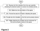
- Embodiments of a method performed by the first communication device 101 operating in the wireless communications network 100 will now be described with reference to the flowchart depicted in Figure 2 .
- the method may comprise some of the following actions. In some embodiments all the actions may be performed. One or more embodiments may be combined, where applicable. All possible combinations are not described to simplify the description. In Figure 2 , optional actions are indicated by dashed boxes.
- an operator may provide a certain wireless service or special offer, such as e.g., "unlimited amount data when at home", fiber replacement, "limited/unlimited” throughput, unlimited for speech calls, a certain bit rate, etc...to a user of the first communication device 101
- the user may first be given to opportunity to select a location where the user would prefer to receive the wireless service.
- a user may desire to receive the wireless service at home, where the user knows that he or she typically performs most of the downloading of large media contents, such as streaming of video.
- the first communication device 101 may provide a request for input from the user, that is a request for a first indication explicitly indicating a desired location to receive the wireless service.
- the indication of the desired location in the first indication is explicit.
- the location may be the home of the user.
- the first indication may be a selection of a list of addresses associated with the user, such as a billing address, a delivery address, or a request to type an address or click on a location on a map, etc....
- the first communication device 101 receives, via an interface 120 of the first communication device 101, the first indication from the user of the first communication device 101, the first indication explicitly indicating a desired location to receive the wireless service.
- the interface 120 may be a screen, microphone, button, or mouse of the first communication device 101, which may be, e.g., a smartphone, desktop, or tablet of the user.
- the first indication may be for example, a tap on a touch screen, e.g., to select an on-screen icon for a billing address associated with the user, or a click on a mouse, a voice signal provided on a microphone, or a movement of the first communication device 101, such as shaking a telephone in a predefined or selected way.
- the first indication may also be an SMS, or an accession to a web page, etc...
- Receiving the first indication may therefore comprise, in some examples, receiving more than one first indication, as in some examples, the user may also indicate the desired location, e.g., its "home area" by, for example, a certain sequence, or calibration process, by for example, sending a plurality of first indications in different geographical points on the desired location.
- the first communication device 101 may, in this Action 202, determine a delimitation of a space 160 corresponding to the indicated desired location.
- the space 160 may be understood as the "box" in space mentioned earlier, in other words, a volume in space, that from the perspective of the wireless communications network 100, may correspond to the desired location by the user, e.g., the address, received from the user in Action 201.
- the location may be understood as a variable as known by the user, whereas the space 160 may be understood as a variable understood by the wireless communications network 100. That is, the space 160 may be understood as a volume wherein the wireless service may be provided by the wireless communications network 100 to the user of the first communication device 101.
- the wireless device may be provided to other communication devices in the space 160, according to e.g., an agreement between the user and an operator the wireless communications network 100.
- the space 160 may correspond to the desired space by the user of the first communication device 101 to receive the wireless service from the wireless communications network 100. Determining may be understood herein as autonomously calculating, or receiving from another communication device in the wireless communications network 100, e.g., the second communication device 102.
- the determining, in this Action 202, of the delimitation may be based on the received first indication. For example, upon receipt of the first indication, the first communication device 101 may tag what specific beam, and at which transmission point or transmission points, the user may be served by, so that a specific wireless service may be bound to the space 160 corresponding that "location". This may be performed, for example, during the calibration process mentioned earlier.
- the delimitation of the space 160 may depend on the associated location, as indicated in Action 201, e.g., whether the indicated desired location is a studio apartment, or a three-story house, etc...
- the space 160 may be at least one of: a geographical space and a radio coverage area. Therefore, the determining of the delimitation in this Action 202 may be based on e.g., GPS measurements for a delimitation of the geographical space, radio signalling information for a delimitation of the radio coverage area, or a combination of both.
- Embodiments herein may take advantage of the fact that massive MIMO systems may hold many and narrow antenna beams, and that each beam may therefore cover a rather small physical area. Beam angular coverage combined with some timing advance measurements may define a rather limited "box” in space. Such "home area bounding box” may represent a user's home area, or other selected area, in which the operator may provide a user with the wireless service, which may be understood also as specific offers. Given the expected angular resolution of emerging massive-MIMO systems, in combination with transmission-user distances in the order of 100 meters, or less, sufficient "spatial resolution" may become available.
- the radio coverage area may be based on a coverage by the one or more beam-formed beams 180, from one or more transmission points operating in the wireless communications network 100.
- the space 160 is covered by a single beam-formed beam transmitted by the second communication device 102, which in this particular example is a transmission point.
- the space 160 may be covered by more than one beam-formed beam transmitted by a single transmission point, or by a combination of beams from different transmission points.
- the resolution of space 160, or bounding area or bounding box may be improved by utilizing Timing Advance (TA) information, to improve the "radial" component of the space 160.
- TA Timing Advance
- the determination of the delimitation of the space 160 may be based on at least one of: a) an identification of one or more beam-formed beams 180 serving the first communication device 101 in the indicated space 160; b) an identification of one or more transmission points serving the first communication device 101 in the indicated space 160; c) a TA measurement between the first communication device 101, when located in the indicated space 160, and a serving beam-formed beam; and d) a measure of signal strength between the first communication device 101, when located in the indicated space 160, and a serving beam-formed beam.
- the first communication device 101 may also be to add statistics of "distance" a beam has to travel from its respective transmitting TP to the first communication device 101, e.g., a CPE, which may be obtained from TA information. If there is more than one serving beam-formed beam, the delimitation may be based on a TA measurement for each serving beam-formed beam. Likewise, if there is more than one serving Transmission Point (TP), there may be a respective TA measurement for each TP associated to the area. It may also be possible that more than one TA is associated to the same beam due to reflections.
- TP Transmission Point
- the combination of a beam or "group of beams” may further pin down the home area, in both, the angular direction and the "radial" distance.
- per-beam utilization statistics may be used to refine identification of a proper beam covering the space 160, e.g., "home beam", in scenarios where two or more beams may be plausible candidates, to improve a performance in beam-border areas of the space 160, e.g., in the home area.
- the TA may need to have a large range, large range of intervals, due to multipath, or multi-path, propagation.
- a TA measurement may correspond a range of values, or to a single value.
- One reason for large differences in TA within "a beam" may stem from that a single beam which may normally be in the dominating path, may sometimes be blocked, and other paths or multi-paths may then become the new main paths.
- Action 202 is optional, since the delimitation of the space 160 may be performed by another communication device in the wireless communications network 100, e.g., by the second communication device 102 or the third communication device 103, using similar methods as those described for this Action.
- the first communication device 101 In order for the first communication device 101 to indicate to the wireless communications network 100 the area 160 where the user desires to receive the wireless service, in this Action 203, the first communication device 101 provides, based on the received first indication, a second indication to the second communication device 102 operating in the wireless communications network 100.
- the second indication indicates that the space 160 corresponding to the indicated desired location, is a desired space to receive the wireless service from the wireless communications network 100.
- Providing may be understood here as sending, e.g., via the one or more beam-formed beams 180 serving the space 160, which may also be referred to as the "home beam".
- An indication may be understood herein as e.g., a signal or a message.
- the second indication may typically be a radio signal, but it may also be another type of signal.
- That the second indication is based on the first indication may be understood to mean that the space 160 corresponds to the desired location, as indicated by the user. This may be understood as being due to the user not knowing the space 160, as the wireless communications network 100 may assign to the desired location, which is known to the user. In other words, the area 160 may be understood as an internal variable of the wireless communications network 100, whereas the location indicated by the user is known to the user.
- the second indication may comprise at least one of: a) the identification of one or more beam-formed beams 180 serving the first communication device 101 in the indicated space 160; b) the identification of one or more transmission points serving the first communication device 101 in the indicated space 160; c) the TA measurement between the first communication device 101, when located in the indicated space 160, and a serving beam-formed beam; and d) the measure of signal strength between the first communication device 101, when located in the indicated space 160, and a serving beam-formed beam.
- the second indication may be based on the determined delimitation.
- the second indication may comprise a logic reference to the space 160, independently of a particular delimitation of the space 160, that the second communication device 102 may then process to itself determine the delimitation of the space 160.
- the second indication may indicate to the second communication device 102 the information received from the user in Action 201, without adding any further information. Nevertheless, the second indication, in any of these examples may enable the second communication device 102 to facilitate providing 304 the wireless service to the first communication device 101, whenever the first communication device 101 may be located in the space 160.
- the first communication device 101 may not have performed Action 202 and determined the delimitation of the space 160, a) the identification of one or more beam-formed beams 180 serving the first communication device 101 in the indicated space 160; b) the identification of one or more transmission points serving the first communication device 101 in the indicated space 160; c) the TA measurement between the first communication device 101, when located in the indicated space 160, and a serving beam-formed beam; and d) the measure of signal strength between the first communication device 101, when located in the indicated space 160, and a serving beam-formed beam.
- the first communication device 101 may be able to detect when the first communication device 101 is in the space 160, e.g., when the user is home.
- the first communication device 101 may be able to detect when it is in the space 160 by receiving a notification or indication from the second communication device 102 informing the first communication device 101 it is in the space 160.
- the first communication device 101 may itself evaluate the same criteria that may have been used to determine the delimitation of the space 160 in Action 202, such as the identification of the one or more beam-formed beams 180 serving the first communication device 101 in the indicated space 160, the identification of the one or more transmission points serving the first communication device 101 in the indicated space 160, the TA measurement between the first communication device 101, when located in the indicated space 160, and the serving beam-formed beam; and the measure of signal strength between the first communication device 101, when located in the indicated space 160, and the serving beam-formed beam.
- said presence in the space 160 may be indicated by e.g., a selected on-screen icon. This may further ease a selection by a user of what wireless service or services may be useful or feasible to invoke.
- a Mobile Broad Band (MBB) subscription may run out of traffic volume if a user downloads streamed hi-definition video, etc.
- MBB Mobile Broad Band
- the first communication device 101 may provide, based on whether or not the first communication device 101 is located in the space 160, a third indication via the interface 120 of the first communication device 101, the third indication indicating that at least one of: a) the first communication device 101 is located in the space 160, whenever the first communication device 101 is located in the space 160, b) the wireless service is available, whenever the first communication device 101 is located in the space 160, and c) the wireless service is unavailable, whenever the first communication device 101 is located outside the space 160.
- the third indication may even indicate that another wireless service is unavailable whenever the first communication device 101 is located in the space 160.
- the third indication may be another type of signal than the first indication and the second indication.
- the third indication may be a banner or a decorative icon on a screen of the first communication device 101, e.g., a smartphone, stating that the first communication device 101 is in its selected "home area", or that the wireless service is available, .e.g., "unlimited data traffic is now available", or a combination of both.
- the third indication may be a sound signal, e.g., a beep emitted by a loudspeaker in the smartphone.
- the wireless service may be a package of different wireless services, e.g., unlimited data traffic and a certain bit rate.
- the third indication may provide a notification to the user when he leaves the space 160 and the wireless service is no longer available.
- the provision of the third indication may be performed upon an instruction from the second communication device 102, which may in some embodiments detect when the first communication device 101 is present in the space 160.
- This Action 204 is optional.
- the first communication device 101 may initiate obtaining 205 the wireless service from the second communication device 102, whenever the first communication device 101 is located in the space 160. That is, whenever the first communication device 101 may be detected to be in the space 160 corresponding to e.g., home, for example, by the second communication device 102, it may obtain from it the wireless service. Thanks to this Action, the user may receive the wireless service, wherever it chooses.
- the wireless service may be obtained whenever the first communication device 101 is located in the determined delimitation of the space 160.
- the second communication device 102 may be one of: a) a network node serving the first communication device 101, and b) the third communication device 103 managing a network node 130 serving the first communication device 101.
- the wireless service may be e.g., "unlimited amount data when at home”, fiber replacement, "limited/unlimited” throughput, unlimited for speech calls, a certain bit rate, etc.
- the method may comprise some of the following actions. In some embodiments all the actions may be performed. One or more embodiments may be combined, where applicable. All possible combinations are not described to simplify the description. In Figure 3 , optional actions are indicated by dashed boxes.
- the second communication device 102 receives the second indication from the first communication device 101 operating in the wireless communications network 100.
- the second indication indicates that the space 160 is the desired space to receive the wireless service from the wireless communications network 100.
- the space 160 corresponds to the location explicitly indicated by the user of the first communication device 101, as the desired location to receive the wireless service.
- the second communication device 102 may receive the second indication, which has already been described, via e.g., the one or more beam-formed beams 180, which may also be referred to as the "home beam".
- the second communication device 102 may be the third communication device 103
- the second communication device 102 may receive the second indication from the first communication device 101 directly or indirectly, via other links such as e.g., the second link 150.
- the space 160 may be at least one of: the geographical space and the radio coverage area.
- the radio coverage area may be based on the coverage by the one or more beam-formed beams 180, from one or more transmission points operating in the wireless communications network 100.
- the received second indication may comprise at least one of: a) the identification of the one or more beam-formed beams 180 serving the first communication device 101 in the indicated space 160; b) the identification of the one or more transmission points serving the first communication device 101 in the indicated space 160; c) the Timing Advance measurement between the first communication device 101, when located in the indicated space 160, and a serving beam-formed beam, of the one or more beam-formed beams 180; and d) the measure of signal strength between the first communication device 101, when located in the indicated space 160, and a serving beam-formed beam, of the one or more beam-formed beams 180.
- the received second indication may trigger the second communication device 102 to obtain at least one of: a) the identification of the one or more beam-formed beams 180 serving the first communication device 101 in the indicated space 160; b) the identification of the one or more transmission points serving the first communication device 101 in the indicated space 160; c) the Timing Advance measurement between the first communication device 101, when located in the indicated space 160, and a serving beam-formed beam, of the one or more beam-formed beams 180; and d) the measure of signal strength between the first communication device 101, when located in the indicated space 160, and a serving beam-formed beam, of the one or more beam-formed beams 180.
- the delimitation may be based on a TA measurement for each serving beam-formed beam.
- the second communication device 102 may have received the second indication it may, in this Action 302, obtain the delimitation of the space 160.
- the obtaining 302 of the delimitation may be based on the received second indication.
- Obtaining may be understood in this Action 302 as autonomously calculating, or as receiving the delimitation, as calculated by the first communication device 101, or by another communication device in the wireless communications network 100, such as the third communication device 103.
- the delimitation of the space 160 may be determined as described before in Action 202.
- this Action 302 is optional.
- the presence of the first communication device 101 in the space 160 may be detected by either the first communication device 101 or the second communication device 102.
- the second communication device 102 may be able to detect when the first communication device 101 is in the space 160 by evaluating the same criteria that may have been used by the first communication device 101 to determine the delimitation of the space 160 in Action 202, such as the identification of the one or more beam-formed beams 180 serving the first communication device 101 in the indicated space 160, the identification of the one or more transmission points serving the first communication device 101 in the indicated space 160, the TA measurement between the first communication device 101, when located in the indicated space 160, and the serving beam-formed beam; and the measure of signal strength between the first communication device 101, when located in the indicated space 160, and the serving beam-formed beam.
- the second communication device 102 may, in this Action 303, initiate providing, based on whether or not the first communication device 101 is located in the space 160, the third indication via the interface 120 of the first communication device 101.
- the third indication may indicate that at least one of: a) the first communication device 101 is located in the space 160, whenever the first communication device 101 is located in the space 160; b) the wireless service is available, whenever the first communication device 101 is located in the space 160, and c) the wireless service is unavailable, whenever the first communication device 101 is located outside the space 160.
- the third indication may be provided, e.g., sent by the second communication device 102 via the one or more beam-formed beams 180.
- the second communication device 102 may be the third communication device 103
- the second communication device 102 may, according to this Action 303, instruct, directly or indirectly, via other links such as e.g., the second link 150, a TP serving the first communication device 101 to provide the third indication to the first communication device 101.
- This Action 303 is optional.
- the second communication device 102 in this Action 304, facilitates providing the wireless service to the first communication device 101, whenever the first communication device 101 is located in the space 160.
- To facilitate providing may be understood herein as to enable the provision of, in this case, of the wireless service, the provision of which may be first initiated elsewhere in the wireless communications network, e.g., in the third communication device 103.
- the facilitating providing 304 of the wireless service to the first communication device 101 may be based on the first communication device 101 being located in the obtained delimitation of the space 160.
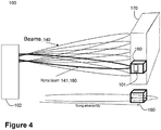
- Figure 4 is a schematic diagram illustrating a non-limiting example of embodiments herein, wherein the second communication device 102 is a TP serving the first communication device 101 when it is located in the space 160.
- the space 160 in this Figure is a home-area bounding box given by a specific beam, the home beam of the one or more beam-formed beams 180, bounding in angular domain, serving the space 160, in conjunction with a specific Timing Advance, bounding in radial domain.
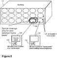
- FIG. 5 is a schematic diagram illustrating a non-limiting example of the provision of the third indication via the interface 120 of the first communication device 101, according to embodiments herein of Action 204.
- the first communication device 101 is in this example a UE, and the space 160 is here a Home area. "Home area presence" may be indicated to the user of the first communication device 101 by displaying a selected on-screen icon, here a "You are home! message, on the interface 120 of the first communication device 101. Whenever the user may leave the space 160, by visiting some neighbors, represented here by empty circles in the building 170, outside of the space 160, the third indication may disappear from the interface 120.
- embodiments herein may be understood to relate to an enablement of a beam-based home-area subscription. That is, embodiments herein may enable the possibility for an operator to provide a selected subscription to a user in a home area, or similar desired location of the user. This may be performed by the fact that a certain "beam direction", or a beam identity, pre-coder or similar, and, in some embodiments, also information of TA, may be used to pinpoint a space corresponding to a desired location of a user, e.g., a "home volume".
- a benefit of the embodiments herein is that they enable to distribute the load of the wireless communications network 100. This is by enabling the provision of wireless services in locations wherein one or a few users may be located, e.g., a user's home, so that a high load may not affect the overall capacity and latency of the wireless communications network 100. This is at least in comparison to a scenario where a high number of users may request usage of resources in a same cell, which may saturate the capacity of the network, and increase its latency.
- the first communication device 101 is configured to operate in the wireless communications network 100.
- the first communication device 101 comprises the following arrangement depicted in Figure 6 .
- the first communication device 101 is configured to, e.g., by means of a receiving module 601 configured to, receive, via the interface 120 of the first communication device 101, the first indication from the user of the first communication device 101, the first indication being configured to explicitly indicate the desired location to receive the wireless service.
- the receiving module 601 may be a processor 605 of the first communication device 101.
- the first communication device 101 is further configured to, e.g., by means of a providing module 602 configured to, provide, based on the first indication configured to be received, the second indication to the second communication device 102 configured to operate in the wireless communications network 100, the second indication being configured to indicate that the space 160 corresponding to the desired location configured to be indicated, is the desired space to receive the wireless service from the wireless communications network 100.
- the providing module 602 may be the processor 605 of the first communication device 101.
- the space 160 may be configured to be at least one of: the geographical space and the radio coverage area.
- the radio coverage area may be configured to be based on the coverage by the one or more beam-formed beams 180 from the one or more transmission points configured to operate in the wireless communications network 100.
- the second indication may comprise at least one of: a) the identification of the one or more beam-formed beams 180 configured to serve the first communication device 101 in the space 160 configured to be indicated; b) the identification of one or more transmission points configured to serve the first communication device 101 in the space 160 configured to be indicated; c) the TA measurement between the first communication device 101, when located in the space 160 configured to be indicated, and the serving beam-formed beam; and d) the measure of signal strength between the first communication device 101, when located in the space 160 configured to be indicated, and the serving beam-formed beam.
- the second indication may be further configured to trigger the second communication device 102 to obtain at least one of: a) the identification of the one or more beam-formed beams 180 configured to serve the first communication device 101 in the space 160 configured to be indicated; b) the identification of the one or more transmission points configured to serve the first communication device 101 in the space 160 configured to be indicated; c)the TA measurement between the first communication device 101, when located in the space 160 configured to be indicated, and the serving beam-formed beam; and d) the measure of signal strength between the first communication device 101, when located in the space 160 configured to be indicated, and the serving beam-formed beam.
- the first communication device 101 is further configured to, e.g., by means of an initiating obtaining module 603 configured to, initiate obtaining the wireless service from the second communication device 102 whenever the first communication device 101 may be located in the space 160.
- the initiating obtaining module 603 may be the processor 605 of the first communication device 101.
- the first communication device 101 may be further configured to, e.g., by means of a determining module 604 configured to, determine the delimitation of the space 160, wherein to determine the delimitation is configured to be based on the first indication configured to be received, wherein the second indication is configured to be based on the delimitation configured to be determined, and wherein the wireless service is configured to be obtained whenever the first communication device 101 is located in the delimitation of the space 160 configured to be determined.
- the determining module 604 may be the processor 605 of the first communication device 101.
- the first communication device 101 may be further configured to, e.g., by means of the providing module 602 configured to, provide, based on whether or not the first communication device 101 is located in the space 160, the third indication via the interface 120 of the first communication device 101, the third indication being configured to indicate that at least one of: a) the first communication device 101 is located in the space 160, whenever the first communication device 101 is located in the space 160, b) the wireless service is available, whenever the first communication device 101 is located in the space 160, and c) the wireless service is unavailable, whenever the first communication device 101 is located outside the space 160.
- the providing module 602 may be the processor 605 of the first communication device 101.
- the embodiments herein as performed by the first communication device 101 may be implemented through one or more processors, such as the processor 605 in the first communication device 101 depicted in Figure 6 , together with computer program code for performing the functions and actions of the embodiments herein.
- the program code mentioned above may also be provided as a computer program product, for instance in the form of a data carrier carrying computer program code for performing the embodiments herein when being loaded into the in the first communication device 101.
- One such carrier may be in the form of a CD ROM disc. It is however feasible with other data carriers such as a memory stick.
- the computer program code may furthermore be provided as pure program code on a server and downloaded to the first communication device 101.
- the computer program code may also be provided as a service from the cloud.
- the processor 605 may comprise one or more circuits, which may also be referred to as one or more modules in some embodiments, each configured to perform the actions carried out by the first communication device 101, as described above in reference to Figure 6 , e.g., the receiving module 601, the providing module 602, the initiating obtaining module 603, and the determining module 604. Also, in some embodiments, the receiving module 601, the providing module 602, the initiating obtaining module 603, and the determining module 604 described above may be implemented as one or more applications running on one or more processors such as the processor 605.
- the first communication device 101 may further comprise a memory 606 comprising one or more memory units.
- the memory 606 may be arranged to be used to store obtained information, such as the information received by the processor 605, store data configurations, scheduling, and applications etc. to perform the methods herein when being executed in the first communication device 101.
- the memory 606 may be in communication with the processor 605. Any of the other information processed by the processor 605 may also be stored in the memory 606.
- information e.g., from the second communication device 102, the user, or the third communication device 203, may be received through a receiving port 607.
- the receiving port 607 may be in communication with the processor 605.
- the receiving port 607 may also be configured to receive other information.
- the processor 605 may be further configured to send messages, e.g., to the user, to the second communication device 102 or the third communication device 203, through a sending port 608, which may be in communication with the processor 605, and the memory 606.
- any module of the first communication device 101 may refer to a combination of analog and digital circuits, and/or one or more processors such as the processor 605 configured with software and/or firmware, e.g. stored in the memory 606, that when executed by the one or more processors such as the processor 605, perform actions as described above, in relation to Figure 2 .
- processors may be included in a single application-specific integrated circuitry (ASIC), or several processors and various digital hardware may be distributed among several separate components, whether individually packaged or assembled into a system-on-a-chip (SoC).
- ASIC application-specific integrated circuitry
- SoC system-on-a-chip
- the methods according to the embodiments described herein for the first communication device 101 may be respectively implemented by means of a computer program 609 product, comprising instructions, i.e., software code portions, which, when executed on at least one processor 605, cause the at least one processor 605 to carry out the actions described herein, as performed by the first communication device 101.
- the computer program 609 product may be stored on a computer-readable storage medium 610.
- the computer-readable storage medium 610, having stored thereon the computer program 609 may comprise instructions which, when executed on at least one processor 605, cause the at least one processor 605 to carry out the actions described herein, as performed by the first communication device 101.
- the computer-readable storage medium 610 may be a non-transitory computer-readable storage medium, such as a CD ROM disc, a memory stick, or stored in the cloud space.
- the computer program 609 product may be stored on a carrier containing the computer program, wherein the carrier is one of an electronic signal, optical signal, radio signal, or the computer-readable storage medium 610, as described above.
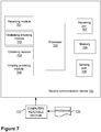
- the second communication device 102 is configured to operate in the wireless communications network 100.
- the second communication device 102 comprises the following arrangement depicted in Figure 7 .
- the second communication device 102 is configured to, e.g., by means of a receiving module 701 configured to, receive the second indication from the first communication device 101 configured to operate in the wireless communications network 100, the second indication being configured to indicate that the space 160 is the desired space to receive the wireless service from the wireless communications network 100, the space 160 corresponding to the location configured to be explicitly indicated by the user of the first communication device 101, as the desired location to receive the wireless service.
- the receiving module 701 may be a processor 705 of the second communication device 102.
- the second communication device 102 is further configured to, e.g., by means of a facilitating providing module 702 configured to, facilitate providing the wireless service to the first communication device 101, whenever the first communication device 101 is located in the space 160.
- the facilitating providing module 702 may be the processor 705 of the second communication device 102.
- the space 160 may be configured to be at least one of: the geographical space and the radio coverage area.
- the radio coverage area may be configured to be based on the coverage by the one or more beam-formed beams 180 from the one or more transmission points configured to operate in the wireless communications network 100.
- the second indication configured to be received may comprise at least one of: a) the identification of the one or more beam-formed beams 180 configured to serve the first communication device 101 in the space 160 configured to be indicated; b) the identification of the one or more transmission points configured to serve the first communication device 101 in the space 160 configured to be indicated; c) the TA measurement between the first communication device 101, when located in the space 160 configured to be indicated, and the serving beam-formed beam; and d) the measure of signal strength between the first communication device 101, when located in the space 160 configured to be indicated, and the serving beam-formed beam.
- the second indication configured to be received may be further configured to trigger the second communication device 102 to obtain at least one of: a) the identification of the one or more beam-formed beams 180 configured to serve the first communication device 101 in the space 160 configured to be indicated; b) the identification of the one or more transmission points configured to serve the first communication device 101 in the space 160 configured to be indicated; c) the TA measurement between the first communication device 101, when located in the space 160 configured to be indicated, and the serving beam-formed beam; and d) the measure of signal strength between the first communication device 101, when located in the space 160 configured to be indicated, and the serving beam-formed beam.
- the second communication device 102 may be further configured to, e.g., by means of an obtaining module 703 configured to, obtain the delimitation of the space 160, wherein to obtain the delimitation may be configured to be based on the second indication configured to be received, and wherein to facilitate providing the wireless service to the first communication device 101 may be configured to be based on the first communication device 101 being located in the delimitation of the space 160 configured to be obtained.
- the obtaining module 703 may be the processor 705 of the second communication device 102.
- the second communication device 102 may be further configured to, e.g., by means of an initiating providing module 704 configured to, initiate providing, based on whether or not the first communication device 101 is located in the space 160, the third indication via the interface 120 of the first communication device 101, the third indication being configured to indicate that at least one of: a) the first communication device 101 is located in the space 160, whenever the first communication device 101 is located in the space 160, b) the wireless service is available, whenever the first communication device 101 is located in the space 160, and c) the wireless service is unavailable, whenever the first communication device 101 is located outside the space 160.
- the initiating providing module 704 may be the processor 705 of the second communication device 102.
- the second communication device 102 may be one of: a) the network node 130 configured to serve the first communication device 101, and b) the third communication device 103 configured to manage the network node 130 that may be configured to serve the first communication device 101.
- the embodiments herein as performed by the second communication device 102 may be implemented through one or more processors, such as the processor 705 in the second communication device 102 depicted in Figure 7 , together with computer program code for performing the functions and actions of the embodiments herein.
- the program code mentioned above may also be provided as a computer program product, for instance in the form of a data carrier carrying computer program code for performing the embodiments herein when being loaded into the in the second communication device 102.
- One such carrier may be in the form of a CD ROM disc. It is however feasible with other data carriers such as a memory stick.
- the computer program code may furthermore be provided as pure program code on a server and downloaded to the second communication device 102.
- the computer program code may also be provided as a service from the cloud.
- the processor 705 may comprise one or more circuits, which may also be referred to as one or more modules in some embodiments, each configured to perform the actions carried out by the second communication device 102, as described above in reference to Figure 7 , e.g., the receiving module 701, the facilitating providing module 702, the obtaining module 703, and the initiating providing module 704. Also, in some embodiments, the receiving module 701, the facilitating providing module 702, the obtaining module 703, and the initiating providing module 704 described above may be implemented as one or more applications running on one or more processors such as the processor 705.
- the second communication device 102 may further comprise a memory 706 comprising one or more memory units.
- the memory 706 may be arranged to be used to store obtained information, such as the information received by the processor 705, store data configurations, scheduling, and applications etc. to perform the methods herein when being executed in the second communication device 102.
- the memory 706 may be in communication with the processor 705. Any of the other information processed by the processor 705 may also be stored in the memory 706.
- information e.g., from the first communication device 101, the user, or the third communication device 203, may be received through a receiving port 707.
- the receiving port 707 may be in communication with the processor 705.
- the receiving port 707 may also be configured to receive other information.
- the processor 705 may be further configured to send messages, e.g., to the user, to the first communication device 101 or the third communication device 203, through a sending port 708, which may be in communication with the processor 705, and the memory 706.
- any module of the second communication device 102 may refer to a combination of analog and digital circuits, and/or one or more processors such as the processor 705 configured with software and/or firmware, e.g. stored in the memory 706, that when executed by the one or more processors such as the processor 705, perform actions as described above, in relation to Figure 3 .
- processors may be included in a single application-specific integrated circuitry (ASIC), or several processors and various digital hardware may be distributed among several separate components, whether individually packaged or assembled into a system-on-a-chip (SoC).
- ASIC application-specific integrated circuitry
- SoC system-on-a-chip
- the methods according to the embodiments described herein for the second communication device 102 may be respectively implemented by means of a computer program 709 product, comprising instructions, i.e., software code portions, which, when executed on at least one processor 705, cause the at least one processor 705 to carry out the actions described herein, as performed by the second communication device 102.
- the computer program 709 product may be stored on a computer-readable storage medium 710.
- the computer-readable storage medium 710, having stored thereon the computer program 709, may comprise instructions which, when executed on at least one processor 705, cause the at least one processor 705 to carry out the actions described herein, as performed by the second communication device 102.
- the computer-readable storage medium 710 may be a non-transitory computer-readable storage medium, such as a CD ROM disc, a memory stick, or stored in the cloud space.
- the computer program 709 product may be stored on a carrier containing the computer program, wherein the carrier is one of an electronic signal, optical signal, radio signal, or the computer-readable storage medium 710, as described above.
- some examples of embodiments herein may also comprise a carrier comprising any of the second indication and the third indication, as respectively described above, wherein the carrier is one of an electronic signal, optical signal, radio signal, or computer readable storage medium.
Landscapes
- Engineering & Computer Science (AREA)
- Computer Networks & Wireless Communication (AREA)
- Signal Processing (AREA)
- Quality & Reliability (AREA)
- Mobile Radio Communication Systems (AREA)
Claims (15)
- Verfahren, durchgeführt durch eine erste Kommunikationsvorrichtung (101), die in einem Drahtloskommunikationsnetzwerk (100) arbeitet, wobei das Verfahren Folgendes umfasst:- Empfangen (201), über eine Schnittstelle (120) der ersten Kommunikationsvorrichtung (101), einer ersten Angabe von einem Benutzer der ersten Kommunikationsvorrichtung (101), wobei die erste Angabe explizit eine gewünschte Stelle zum Empfangen eines Drahtlosdienstes angibt,- Bereitstellen (203), basierend auf der empfangenen ersten Angabe, einer zweiten Angabe an eine zweite Kommunikationsvorrichtung (102), die in dem Drahtloskommunikationsnetzwerk (100) arbeitet, wobei die zweite Angabe angibt, dass ein Raum (160) entsprechend der angegebenen gewünschten Stelle ein gewünschter Raum zum Empfangen des Drahtlosdienstes von dem Drahtloskommunikationsnetzwerk (100) ist, und- Initiieren des Erhaltens (205) des Drahtlosdienstes von der zweiten Kommunikationsvorrichtung (102), nur wenn sich die erste Kommunikationsvorrichtung (101) in dem Raum (160) befindet, wobei die erste Kommunikationsvorrichtung (101) durch einen oder mehrere strahlgeformte Strahlen, die den Raum (160) bedienen, bedient wird, nur wenn sich die erste Kommunikationsvorrichtung (101) in dem Raum (160) befindet, und wobei der eine oder die mehreren strahlgeformten Strahlen, die den Raum (160) bedienen, zumindest eines von einem ersten Satz von einem oder mehreren strahlgeformten Strahlen (141) übertragen durch die zweite Kommunikationsvorrichtung (120) umfassen.
- Verfahren nach Anspruch 1, wobei der Raum (160) zumindest eines des Folgenden ist: ein geographischer Raum und ein Funkabdeckungsbereich, und wobei der Funkabdeckungsbereich auf einer Abdeckung durch einen oder mehrere strahlgeformte Strahlen (180) von einem oder mehreren Übertragungspunkten basiert, die in dem Drahtloskommunikationsnetzwerk (100) arbeiten.
- Verfahren nach einem der Ansprüche 1-2, ferner umfassend:- Bestimmen (202) einer Begrenzung des Raums (160), wobei das Bestimmen (202) der Begrenzung auf der empfangenen ersten Angabe basiert, wobei die zweite Angabe auf der bestimmten Begrenzung basiert, und wobei der Drahtlosdienst erhalten wird, nur wenn sich die erste Kommunikationsvorrichtung (101) in der bestimmten Begrenzung des Raums (160) befindet.
- Verfahren nach einem der Ansprüche 1-3, wobei die zweite Angabe zumindest eines des Folgenden umfasst:a. eine Identifizierung des einen oder der mehreren strahlgeformten Strahlen (180), welche die erste Kommunikationsvorrichtung (101) in dem angegebenen Raum (160) bedienen;b. eine Identifizierung von einem oder mehreren Übergangspunkten, welche die erste Kommunikationsvorrichtung (101) in dem angegebenen Raum (160) bedienen;c. eine Zeitvorsprungsmessung zwischen der ersten Kommunikationsvorrichtung (101), wenn sie sich in dem angegebenen Raum (160) befindet, und einem bedienenden strahlgeformten Strahl; undd. ein Maß der Signalstärke zwischen der ersten Kommunikationsvorrichtung (101), wenn sie sich in dem angegebenen Raum (160) befindet, und dem bedienenden strahlgeformten Strahl.
- Verfahren nach einem der Ansprüche 1-3, wobei die zweite Angabe die zweite Kommunikationsvorrichtung (102) auslöst, um zumindest eines des Folgenden zu erhalten:a. eine Identifizierung des einen oder der mehreren strahlgeformten Strahlen (180), welche die erste Kommunikationsvorrichtung (101) in dem angegebenen Raum (160) bedienen;b. eine Identifizierung von einem oder mehreren Übergangspunkten, welche die erste Kommunikationsvorrichtung (101) in dem angegebenen Raum (160) bedienen;c. eine Zeitvorsprungsmessung zwischen der ersten Kommunikationsvorrichtung (101), wenn sie sich in dem angegebenen Raum (160) befindet, und einem bedienenden strahlgeformten Strahl; undd. ein Maß der Signalstärke zwischen der ersten Kommunikationsvorrichtung (101), wenn sie sich in dem angegebenen Raum (160) befindet, und dem bedienenden strahlgeformten Strahl.
- Verfahren nach einem der Ansprüche 1-5, ferner umfassend:- Bereitstellen (204), basierend darauf, ob sich die erste Kommunikationsvorrichtung (101) in dem Raum 160 befindet oder nicht, einer dritten Angabe über die Schnittstelle (120) der ersten Kommunikationsvorrichtung (101), wobei die dritte Angabe angibt, dass zumindest eines des Folgenden gilt: a) die erste Kommunikationsvorrichtung (101) befindet sich in dem Raum (160), nur wenn sich die erste Kommunikationsvorrichtung (101) in dem Raum (160) befindet, b) der Drahtlosdienst ist verfügbar, nur wenn sich die erste Kommunikationsvorrichtung (101) in dem Raum (160) befindet, und c) der Drahtlosdienst ist nicht verfügbar, wenn sich die erste Kommunikationsvorrichtung (101) außerhalb des Raumes (160) befindet.
- Verfahren, durchgeführt durch eine zweite Kommunikationsvorrichtung (102), die in einem Drahtloskommunikationsnetzwerk (100) arbeitet, wobei das Verfahren Folgendes umfasst:- Empfangen (301) einer zweiten Angabe von einer ersten Kommunikationsvorrichtung (101), die in dem Drahtloskommunikationsnetzwerk (100) arbeitet, wobei die zweite Angabe angibt, dass ein Raum (160) ein gewünschter Raum zum Empfangen eines Drahtlosdienstes von dem Drahtloskommunikationsnetzwerk (100) ist, wobei der Raum (160) einem Ort entspricht, der explizit durch einen Benutzer der ersten Kommunikationsvorrichtung (101) als ein gewünschter Ort zum Empfangen des Drahtlosdienstes angegeben wird, und- Vereinfachen des Bereitstellens (304) des Drahtlosdienstes an die erste Kommunikationsvorrichtung (101), nur wenn sich die erste Kommunikationsvorrichtung (101) in dem Raum (160) befindet, wobei die erste Kommunikationsvorrichtung (101) durch einen oder mehrere strahlgeformte Strahlen bedient wird, die den Raum (160) bedienen, nur wenn sich die erste Kommunikationsvorrichtung (101) in dem Raum (160) befindet, und wobei der eine oder die mehreren strahlgeformten Strahlen, die den Raum (160) bedienen, zumindest eines von einem ersten Satz von einem oder mehreren strahlgeformten Strahlen (141) übertragen durch die zweite Kommunikationsvorrichtung (120) umfassen.
- Verfahren nach Anspruch 7, wobei der Raum (160) zumindest einer des Folgenden ist: ein geographischer Raum und ein Funkabdeckungsbereich.
- Verfahren nach Anspruch 8, wobei der Funkabdeckungsbereich auf einer Abdeckung durch einen oder mehrere strahlgeformte Strahlen (180) von einem oder mehreren Übertragungspunkten basiert, die in dem Drahtloskommunikationsnetzwerk (100) arbeiten.
- Verfahren nach einem der Ansprüche 7-9, ferner umfassend:- Erhalten (302) einer Begrenzung des Raums (160), wobei das Erhalten (302) der Begrenzung auf der empfangenen zweiten Angabe basiert, wobei das Vereinfachen des Bereitstellens (304) des Drahtlosdienstes an die erste Kommunikationsvorrichtung (101) darauf basiert, dass sich die erste Kommunikationsvorrichtung (101) in der erhaltenen Begrenzung des Raumes (160) befindet.
- Verfahren nach einem der Ansprüche 7-10, ferner umfassend:- Initiieren des Bereitstellens (303), basierend darauf, ob sich die erste Kommunikationsvorrichtung (101) in dem Raum 160 befindet oder nicht, einer dritten Angabe über die Schnittstelle (120) der ersten Kommunikationsvorrichtung (101), wobei die dritte Angabe angibt, dass zumindest eines des Folgenden gilt: a) die erste Kommunikationsvorrichtung (101) befindet sich in dem Raum (160), nur wenn sich die erste Kommunikationsvorrichtung (101) in dem Raum (160) befindet, b) der Drahtlosdienst ist verfügbar, nur wenn sich die erste Kommunikationsvorrichtung (101) in dem Raum (160) befindet, und c) der Drahtlosdienst ist nicht verfügbar, wenn sich die erste Kommunikationsvorrichtung (101) außerhalb des Raumes (160) befindet.
- Verfahren nach einem der Ansprüche 7-11, wobei die empfangene zweite Angabe zumindest eines des Folgenden umfasst:a. eine Identifizierung des einen oder der mehreren strahlgeformten Strahlen (180), welche die erste Kommunikationsvorrichtung (101) in dem angegebenen Raum (160) bedienen;b. eine Identifizierung von einem oder mehreren Übergangspunkten, welche die erste Kommunikationsvorrichtung (101) in dem angegebenen Raum (160) bedienen;c. eine Zeitvorsprungsmessung zwischen der ersten Kommunikationsvorrichtung (101), wenn sie sich in dem angegebenen Raum (160) befindet, und einem bedienenden strahlgeformten Strahl; undd. ein Maß der Signalstärke zwischen der ersten Kommunikationsvorrichtung (101), wenn sie sich in dem angegebenen Raum (160) befindet, und dem bedienenden strahlgeformten Strahl.
- Verfahren nach einem der Ansprüche 7-12, wobei die empfangene zweite Angabe die zweite Kommunikationsvorrichtung (102) auslöst, um zumindest eines des Folgenden zu erhalten:a. eine Identifizierung des einen oder der mehreren strahlgeformten Strahlen (180), welche die erste Kommunikationsvorrichtung (101) in dem angegebenen Raum (160) bedienen;b. eine Identifizierung von einem oder mehreren Übergangspunkten, welche die erste Kommunikationsvorrichtung (101) in dem angegebenen Raum (160) bedienen;c. eine Zeitvorsprungsmessung zwischen der ersten Kommunikationsvorrichtung (101), wenn sie sich in dem angegebenen Raum (160) befindet, und einem bedienenden strahlgeformten Strahl; undd. ein Maß der Signalstärke zwischen der ersten Kommunikationsvorrichtung (101), wenn sie sich in dem angegebenen Raum (160) befindet, und dem bedienenden strahlgeformten Strahl.
- Erste Kommunikationsvorrichtung (101), die konfiguriert ist, um in einem Drahtloskommunikationsnetzwerk (100) zu arbeiten, wobei die erste Kommunikationsvorrichtung (101) konfiguriert für Folgendes ist:- Empfangen, über eine Schnittstelle (120) der ersten Kommunikationsvorrichtung (101), einer ersten Angabe von einem Benutzer der ersten Kommunikationsvorrichtung (101), wobei die erste Angabe konfiguriert ist, um explizit eine gewünschte Stelle zum Empfangen eines Drahtlosdienstes anzugeben,- Bereitstellen, basierend auf der ersten Angabe, die konfiguriert ist, um empfangen zu werden, einer zweiten Angabe an eine zweite Kommunikationsvorrichtung (102), die konfiguriert ist, um in dem Drahtloskommunikationsnetzwerk (100) zu arbeiten, wobei die zweite Angabe konfiguriert ist, um anzugeben, dass ein Raum (160) entsprechend der gewünschten Stelle, die konfiguriert ist, um angegeben zu werden, ein gewünschter Raum zum Empfangen des Drahtlosdienstes von dem Drahtloskommunikationsnetzwerk (100) ist, und- Initiieren des Erhaltens des Drahtlosdienstes von der zweiten Kommunikationsvorrichtung (102), nur wenn sich die erste Kommunikationsvorrichtung (101) in dem Raum (160) befindet, wobei die erste Kommunikationsvorrichtung (101) durch einen oder mehrere strahlgeformte Strahlen, die den Raum (160) bedienen, bedient wird, nur wenn sich die erste Kommunikationsvorrichtung (101) in dem Raum (160) befindet, und wobei der eine oder die mehreren strahlgeformten Strahlen, die den Raum (160) bedienen, zumindest eines von einem ersten Satz von einem oder mehreren strahlgeformten Strahlen (141) übertragen durch die zweite Kommunikationsvorrichtung (120) umfassen.
- Zweite Kommunikationsvorrichtung (102), die konfiguriert ist, um in einem Drahtloskommunikationsnetzwerk (100) zu arbeiten, wobei die zweite Kommunikationsvorrichtung (102) ferner für Folgendes konfiguriert ist:- Empfangen einer zweiten Angabe von einer ersten Kommunikationsvorrichtung (101), die konfiguriert ist, um in dem Drahtloskommunikationsnetzwerk (100) zu arbeiten, wobei die zweite Angabe konfiguriert ist, um anzugeben, dass ein Raum (160) ein gewünschter Raum zum Empfangen eines Drahtlosdienstes von dem Drahtloskommunikationsnetzwerk (100) ist, wobei der Raum (160) einem Ort entspricht, der konfiguriert ist, um explizit durch einen Benutzer der ersten Kommunikationsvorrichtung (101) als ein gewünschter Ort zum Empfangen des Drahtlosdienstes angegeben zu werden, und- Vereinfachen des Bereitstellens des Drahtlosdienstes an die erste Kommunikationsvorrichtung (101), nur wenn sich die erste Kommunikationsvorrichtung (101) in dem Raum (160) befindet, wobei die erste Kommunikationsvorrichtung (101) durch einen oder mehrere strahlgeformte Strahlen bedient wird, die den Raum (160) bedienen, nur wenn sich die erste Kommunikationsvorrichtung (101) in dem Raum (160) befindet, und wobei der eine oder die mehreren strahlgeformten Strahlen, die den Raum (160) bedienen, zumindest eines von einem ersten Satz von einem oder mehreren strahlgeformten Strahlen (141) übertragen durch die zweite Kommunikationsvorrichtung (120) umfassen.
Applications Claiming Priority (1)
| Application Number | Priority Date | Filing Date | Title |
|---|---|---|---|
| PCT/SE2017/050035 WO2018132045A1 (en) | 2017-01-16 | 2017-01-16 | First communication device, second communication device, and methods performed thereby for managing a wireless service |
Publications (2)
| Publication Number | Publication Date |
|---|---|
| EP3569032A1 EP3569032A1 (de) | 2019-11-20 |
| EP3569032B1 true EP3569032B1 (de) | 2021-06-02 |
Family
ID=57944473
Family Applications (1)
| Application Number | Title | Priority Date | Filing Date |
|---|---|---|---|
| EP17702437.9A Active EP3569032B1 (de) | 2017-01-16 | 2017-01-16 | Erste kommunikationsvorrichtung, zweite kommunikationsvorrichtung und davon durchgeführtes verfahren zur verwaltung eines drahtlosdienstes |
Country Status (3)
| Country | Link |
|---|---|
| US (1) | US10687223B2 (de) |
| EP (1) | EP3569032B1 (de) |
| WO (1) | WO2018132045A1 (de) |
Family Cites Families (4)
| Publication number | Priority date | Publication date | Assignee | Title |
|---|---|---|---|---|
| US8537003B2 (en) | 2009-05-20 | 2013-09-17 | Microsoft Corporation | Geographic reminders |
| US9131343B2 (en) * | 2011-03-31 | 2015-09-08 | Teaneck Enterprises, Llc | System and method for automated proximity-based social check-ins |
| US20130159463A1 (en) | 2011-12-20 | 2013-06-20 | Frisco Smartapps, LLC | Method and system for targeted transmission of content |
| PT3890206T (pt) * | 2015-09-14 | 2024-07-18 | Nokia Solutions & Networks Oy | Transmissão de feixe formado num sistema celular |
-
2017
- 2017-01-16 WO PCT/SE2017/050035 patent/WO2018132045A1/en not_active Ceased
- 2017-01-16 US US16/475,968 patent/US10687223B2/en active Active
- 2017-01-16 EP EP17702437.9A patent/EP3569032B1/de active Active
Non-Patent Citations (1)
| Title |
|---|
| None * |
Also Published As
| Publication number | Publication date |
|---|---|
| US10687223B2 (en) | 2020-06-16 |
| US20190357060A1 (en) | 2019-11-21 |
| EP3569032A1 (de) | 2019-11-20 |
| WO2018132045A1 (en) | 2018-07-19 |
Similar Documents
| Publication | Publication Date | Title |
|---|---|---|
| US10763949B1 (en) | Fifth generation new radio repeater state machine | |
| US11006304B2 (en) | Beam measurement in a wireless communication network for identifying candidate beams for a handover | |
| US10897302B2 (en) | Beam sweep or scan in a wireless communication system | |
| KR20220066200A (ko) | 무선 네트워크용 공동 빔 보고 | |
| JP2022549432A (ja) | 非地上ネットワーク(ntn)において偏波モードを設定するための方法 | |
| KR102494376B1 (ko) | 무선 통신을 위해 사용되는 디바이스, 스펙트럼 관리 디바이스 및 사용자 장비 | |
| US20180175992A1 (en) | A Wireless Device, A Radio Network Node, And Methods Therein | |
| US10790897B1 (en) | Systems and methods for selecting radio beams | |
| US11350329B2 (en) | Signal management method, related apparatus, and related system | |
| CN109478919B (zh) | 基站和用户设备 | |
| US20220191711A1 (en) | Dynamic radio architecture beam pattern control | |
| JP2024514805A (ja) | リソースインデックス情報に基づくリソースセット処理優先度付け決定 | |
| US9461790B2 (en) | Methods and systems for controlling cells in a network | |
| WO2024051630A1 (zh) | 定位方法、装置、终端及网络侧设备 | |
| US12317134B2 (en) | Managing a baseband network policy | |
| US20240305357A1 (en) | Optimized beam selection using quasi-colocation information | |
| US20230361979A1 (en) | Selection of tdd patterns for dl and ul communication | |
| CN109644395A (zh) | 处理单元和其中用于启动小区激活的方法 | |
| EP3569032B1 (de) | Erste kommunikationsvorrichtung, zweite kommunikationsvorrichtung und davon durchgeführtes verfahren zur verwaltung eines drahtlosdienstes | |
| US10985821B1 (en) | Dynamic beam pattern control using device velocity | |
| US20200280912A1 (en) | Cell selection and resource allocation thresholds | |
| US20250184797A1 (en) | Method for enhanced measurement and reporting | |
| US12004010B2 (en) | Managing a core network policy | |
| WO2025113937A1 (en) | Method for enhanced measurement and reporting | |
| US20200154445A1 (en) | Small cell resource configuration method and device for a wireless mobile network |
Legal Events
| Date | Code | Title | Description |
|---|---|---|---|
| STAA | Information on the status of an ep patent application or granted ep patent |
Free format text: STATUS: UNKNOWN |
|
| STAA | Information on the status of an ep patent application or granted ep patent |
Free format text: STATUS: THE INTERNATIONAL PUBLICATION HAS BEEN MADE |
|
| PUAI | Public reference made under article 153(3) epc to a published international application that has entered the european phase |
Free format text: ORIGINAL CODE: 0009012 |
|
| STAA | Information on the status of an ep patent application or granted ep patent |
Free format text: STATUS: REQUEST FOR EXAMINATION WAS MADE |
|
| 17P | Request for examination filed |
Effective date: 20190808 |
|
| AK | Designated contracting states |
Kind code of ref document: A1 Designated state(s): AL AT BE BG CH CY CZ DE DK EE ES FI FR GB GR HR HU IE IS IT LI LT LU LV MC MK MT NL NO PL PT RO RS SE SI SK SM TR |
|
| AX | Request for extension of the european patent |
Extension state: BA ME |
|
| STAA | Information on the status of an ep patent application or granted ep patent |
Free format text: STATUS: EXAMINATION IS IN PROGRESS |
|
| DAV | Request for validation of the european patent (deleted) | ||
| DAX | Request for extension of the european patent (deleted) | ||
| 17Q | First examination report despatched |
Effective date: 20200416 |
|
| GRAP | Despatch of communication of intention to grant a patent |
Free format text: ORIGINAL CODE: EPIDOSNIGR1 |
|
| STAA | Information on the status of an ep patent application or granted ep patent |
Free format text: STATUS: GRANT OF PATENT IS INTENDED |
|
| INTG | Intention to grant announced |
Effective date: 20210318 |
|
| GRAS | Grant fee paid |
Free format text: ORIGINAL CODE: EPIDOSNIGR3 |
|
| GRAA | (expected) grant |
Free format text: ORIGINAL CODE: 0009210 |
|
| STAA | Information on the status of an ep patent application or granted ep patent |
Free format text: STATUS: THE PATENT HAS BEEN GRANTED |
|
| REG | Reference to a national code |
Ref country code: CH Ref legal event code: EP |
|
| AK | Designated contracting states |
Kind code of ref document: B1 Designated state(s): AL AT BE BG CH CY CZ DE DK EE ES FI FR GB GR HR HU IE IS IT LI LT LU LV MC MK MT NL NO PL PT RO RS SE SI SK SM TR |
|
| REG | Reference to a national code |
Ref country code: GB Ref legal event code: FG4D |
|
| REG | Reference to a national code |
Ref country code: AT Ref legal event code: REF Ref document number: 1399673 Country of ref document: AT Kind code of ref document: T Effective date: 20210615 |
|
| REG | Reference to a national code |
Ref country code: IE Ref legal event code: FG4D |
|
| REG | Reference to a national code |
Ref country code: DE Ref legal event code: R096 Ref document number: 602017039612 Country of ref document: DE |
|
| REG | Reference to a national code |
Ref country code: NL Ref legal event code: FP |
|
| REG | Reference to a national code |
Ref country code: LT Ref legal event code: MG9D |
|
| PG25 | Lapsed in a contracting state [announced via postgrant information from national office to epo] |
Ref country code: HR Free format text: LAPSE BECAUSE OF FAILURE TO SUBMIT A TRANSLATION OF THE DESCRIPTION OR TO PAY THE FEE WITHIN THE PRESCRIBED TIME-LIMIT Effective date: 20210602 Ref country code: BG Free format text: LAPSE BECAUSE OF FAILURE TO SUBMIT A TRANSLATION OF THE DESCRIPTION OR TO PAY THE FEE WITHIN THE PRESCRIBED TIME-LIMIT Effective date: 20210902 Ref country code: LT Free format text: LAPSE BECAUSE OF FAILURE TO SUBMIT A TRANSLATION OF THE DESCRIPTION OR TO PAY THE FEE WITHIN THE PRESCRIBED TIME-LIMIT Effective date: 20210602 Ref country code: FI Free format text: LAPSE BECAUSE OF FAILURE TO SUBMIT A TRANSLATION OF THE DESCRIPTION OR TO PAY THE FEE WITHIN THE PRESCRIBED TIME-LIMIT Effective date: 20210602 |
|
| REG | Reference to a national code |
Ref country code: AT Ref legal event code: MK05 Ref document number: 1399673 Country of ref document: AT Kind code of ref document: T Effective date: 20210602 |
|
| PG25 | Lapsed in a contracting state [announced via postgrant information from national office to epo] |
Ref country code: PL Free format text: LAPSE BECAUSE OF FAILURE TO SUBMIT A TRANSLATION OF THE DESCRIPTION OR TO PAY THE FEE WITHIN THE PRESCRIBED TIME-LIMIT Effective date: 20210602 Ref country code: NO Free format text: LAPSE BECAUSE OF FAILURE TO SUBMIT A TRANSLATION OF THE DESCRIPTION OR TO PAY THE FEE WITHIN THE PRESCRIBED TIME-LIMIT Effective date: 20210902 Ref country code: RS Free format text: LAPSE BECAUSE OF FAILURE TO SUBMIT A TRANSLATION OF THE DESCRIPTION OR TO PAY THE FEE WITHIN THE PRESCRIBED TIME-LIMIT Effective date: 20210602 Ref country code: SE Free format text: LAPSE BECAUSE OF FAILURE TO SUBMIT A TRANSLATION OF THE DESCRIPTION OR TO PAY THE FEE WITHIN THE PRESCRIBED TIME-LIMIT Effective date: 20210602 Ref country code: LV Free format text: LAPSE BECAUSE OF FAILURE TO SUBMIT A TRANSLATION OF THE DESCRIPTION OR TO PAY THE FEE WITHIN THE PRESCRIBED TIME-LIMIT Effective date: 20210602 Ref country code: GR Free format text: LAPSE BECAUSE OF FAILURE TO SUBMIT A TRANSLATION OF THE DESCRIPTION OR TO PAY THE FEE WITHIN THE PRESCRIBED TIME-LIMIT Effective date: 20210903 |
|
| PG25 | Lapsed in a contracting state [announced via postgrant information from national office to epo] |
Ref country code: CZ Free format text: LAPSE BECAUSE OF FAILURE TO SUBMIT A TRANSLATION OF THE DESCRIPTION OR TO PAY THE FEE WITHIN THE PRESCRIBED TIME-LIMIT Effective date: 20210602 Ref country code: EE Free format text: LAPSE BECAUSE OF FAILURE TO SUBMIT A TRANSLATION OF THE DESCRIPTION OR TO PAY THE FEE WITHIN THE PRESCRIBED TIME-LIMIT Effective date: 20210602 Ref country code: AT Free format text: LAPSE BECAUSE OF FAILURE TO SUBMIT A TRANSLATION OF THE DESCRIPTION OR TO PAY THE FEE WITHIN THE PRESCRIBED TIME-LIMIT Effective date: 20210602 Ref country code: ES Free format text: LAPSE BECAUSE OF FAILURE TO SUBMIT A TRANSLATION OF THE DESCRIPTION OR TO PAY THE FEE WITHIN THE PRESCRIBED TIME-LIMIT Effective date: 20210602 Ref country code: PT Free format text: LAPSE BECAUSE OF FAILURE TO SUBMIT A TRANSLATION OF THE DESCRIPTION OR TO PAY THE FEE WITHIN THE PRESCRIBED TIME-LIMIT Effective date: 20211004 Ref country code: RO Free format text: LAPSE BECAUSE OF FAILURE TO SUBMIT A TRANSLATION OF THE DESCRIPTION OR TO PAY THE FEE WITHIN THE PRESCRIBED TIME-LIMIT Effective date: 20210602 Ref country code: SK Free format text: LAPSE BECAUSE OF FAILURE TO SUBMIT A TRANSLATION OF THE DESCRIPTION OR TO PAY THE FEE WITHIN THE PRESCRIBED TIME-LIMIT Effective date: 20210602 Ref country code: SM Free format text: LAPSE BECAUSE OF FAILURE TO SUBMIT A TRANSLATION OF THE DESCRIPTION OR TO PAY THE FEE WITHIN THE PRESCRIBED TIME-LIMIT Effective date: 20210602 |
|
| REG | Reference to a national code |
Ref country code: DE Ref legal event code: R097 Ref document number: 602017039612 Country of ref document: DE |
|
| PLBE | No opposition filed within time limit |
Free format text: ORIGINAL CODE: 0009261 |
|
| STAA | Information on the status of an ep patent application or granted ep patent |
Free format text: STATUS: NO OPPOSITION FILED WITHIN TIME LIMIT |
|
| PG25 | Lapsed in a contracting state [announced via postgrant information from national office to epo] |
Ref country code: DK Free format text: LAPSE BECAUSE OF FAILURE TO SUBMIT A TRANSLATION OF THE DESCRIPTION OR TO PAY THE FEE WITHIN THE PRESCRIBED TIME-LIMIT Effective date: 20210602 |
|
| 26N | No opposition filed |
Effective date: 20220303 |
|
| PG25 | Lapsed in a contracting state [announced via postgrant information from national office to epo] |
Ref country code: AL Free format text: LAPSE BECAUSE OF FAILURE TO SUBMIT A TRANSLATION OF THE DESCRIPTION OR TO PAY THE FEE WITHIN THE PRESCRIBED TIME-LIMIT Effective date: 20210602 |
|
| PG25 | Lapsed in a contracting state [announced via postgrant information from national office to epo] |
Ref country code: IT Free format text: LAPSE BECAUSE OF FAILURE TO SUBMIT A TRANSLATION OF THE DESCRIPTION OR TO PAY THE FEE WITHIN THE PRESCRIBED TIME-LIMIT Effective date: 20210602 |
|
| PG25 | Lapsed in a contracting state [announced via postgrant information from national office to epo] |
Ref country code: MC Free format text: LAPSE BECAUSE OF FAILURE TO SUBMIT A TRANSLATION OF THE DESCRIPTION OR TO PAY THE FEE WITHIN THE PRESCRIBED TIME-LIMIT Effective date: 20210602 |
|
| REG | Reference to a national code |
Ref country code: CH Ref legal event code: PL |
|
| REG | Reference to a national code |
Ref country code: BE Ref legal event code: MM Effective date: 20220131 |
|
| PG25 | Lapsed in a contracting state [announced via postgrant information from national office to epo] |
Ref country code: LU Free format text: LAPSE BECAUSE OF NON-PAYMENT OF DUE FEES Effective date: 20220116 |
|
| PG25 | Lapsed in a contracting state [announced via postgrant information from national office to epo] |
Ref country code: FR Free format text: LAPSE BECAUSE OF NON-PAYMENT OF DUE FEES Effective date: 20220131 Ref country code: BE Free format text: LAPSE BECAUSE OF NON-PAYMENT OF DUE FEES Effective date: 20220131 |
|
| PG25 | Lapsed in a contracting state [announced via postgrant information from national office to epo] |
Ref country code: LI Free format text: LAPSE BECAUSE OF NON-PAYMENT OF DUE FEES Effective date: 20220131 Ref country code: CH Free format text: LAPSE BECAUSE OF NON-PAYMENT OF DUE FEES Effective date: 20220131 |
|
| PG25 | Lapsed in a contracting state [announced via postgrant information from national office to epo] |
Ref country code: IE Free format text: LAPSE BECAUSE OF NON-PAYMENT OF DUE FEES Effective date: 20220116 |
|
| PGFP | Annual fee paid to national office [announced via postgrant information from national office to epo] |
Ref country code: GB Payment date: 20230127 Year of fee payment: 7 Ref country code: DE Payment date: 20230127 Year of fee payment: 7 |
|
| PGFP | Annual fee paid to national office [announced via postgrant information from national office to epo] |
Ref country code: NL Payment date: 20230126 Year of fee payment: 7 |
|
| PG25 | Lapsed in a contracting state [announced via postgrant information from national office to epo] |
Ref country code: MK Free format text: LAPSE BECAUSE OF FAILURE TO SUBMIT A TRANSLATION OF THE DESCRIPTION OR TO PAY THE FEE WITHIN THE PRESCRIBED TIME-LIMIT Effective date: 20210602 Ref country code: CY Free format text: LAPSE BECAUSE OF FAILURE TO SUBMIT A TRANSLATION OF THE DESCRIPTION OR TO PAY THE FEE WITHIN THE PRESCRIBED TIME-LIMIT Effective date: 20210602 |
|
| PG25 | Lapsed in a contracting state [announced via postgrant information from national office to epo] |
Ref country code: HU Free format text: LAPSE BECAUSE OF FAILURE TO SUBMIT A TRANSLATION OF THE DESCRIPTION OR TO PAY THE FEE WITHIN THE PRESCRIBED TIME-LIMIT; INVALID AB INITIO Effective date: 20170116 |
|
| PG25 | Lapsed in a contracting state [announced via postgrant information from national office to epo] |
Ref country code: TR Free format text: LAPSE BECAUSE OF FAILURE TO SUBMIT A TRANSLATION OF THE DESCRIPTION OR TO PAY THE FEE WITHIN THE PRESCRIBED TIME-LIMIT Effective date: 20210602 |
|
| REG | Reference to a national code |
Ref country code: DE Ref legal event code: R119 Ref document number: 602017039612 Country of ref document: DE |
|
| REG | Reference to a national code |
Ref country code: NL Ref legal event code: MM Effective date: 20240201 |
|
| GBPC | Gb: european patent ceased through non-payment of renewal fee |
Effective date: 20240116 |
|
| PG25 | Lapsed in a contracting state [announced via postgrant information from national office to epo] |
Ref country code: MT Free format text: LAPSE BECAUSE OF FAILURE TO SUBMIT A TRANSLATION OF THE DESCRIPTION OR TO PAY THE FEE WITHIN THE PRESCRIBED TIME-LIMIT Effective date: 20210602 |
|
| PG25 | Lapsed in a contracting state [announced via postgrant information from national office to epo] |
Ref country code: DE Free format text: LAPSE BECAUSE OF NON-PAYMENT OF DUE FEES Effective date: 20240801 |
|
| PG25 | Lapsed in a contracting state [announced via postgrant information from national office to epo] |
Ref country code: GB Free format text: LAPSE BECAUSE OF NON-PAYMENT OF DUE FEES Effective date: 20240116 |
|
| PG25 | Lapsed in a contracting state [announced via postgrant information from national office to epo] |
Ref country code: NL Free format text: LAPSE BECAUSE OF NON-PAYMENT OF DUE FEES Effective date: 20240201 |
|
| PG25 | Lapsed in a contracting state [announced via postgrant information from national office to epo] |
Ref country code: NL Free format text: LAPSE BECAUSE OF NON-PAYMENT OF DUE FEES Effective date: 20240201 Ref country code: GB Free format text: LAPSE BECAUSE OF NON-PAYMENT OF DUE FEES Effective date: 20240116 Ref country code: DE Free format text: LAPSE BECAUSE OF NON-PAYMENT OF DUE FEES Effective date: 20240801 |