EP3569112B1 - A sealed container for beverages - Google Patents
A sealed container for beverages Download PDFInfo
- Publication number
- EP3569112B1 EP3569112B1 EP19174977.9A EP19174977A EP3569112B1 EP 3569112 B1 EP3569112 B1 EP 3569112B1 EP 19174977 A EP19174977 A EP 19174977A EP 3569112 B1 EP3569112 B1 EP 3569112B1
- Authority
- EP
- European Patent Office
- Prior art keywords
- cup
- sealing lid
- paperboard
- beverage
- lip
- Prior art date
- Legal status (The legal status is an assumption and is not a legal conclusion. Google has not performed a legal analysis and makes no representation as to the accuracy of the status listed.)
- Active
Links
Images








Classifications
-
- B—PERFORMING OPERATIONS; TRANSPORTING
- B65—CONVEYING; PACKING; STORING; HANDLING THIN OR FILAMENTARY MATERIAL
- B65D—CONTAINERS FOR STORAGE OR TRANSPORT OF ARTICLES OR MATERIALS, e.g. BAGS, BARRELS, BOTTLES, BOXES, CANS, CARTONS, CRATES, DRUMS, JARS, TANKS, HOPPERS, FORWARDING CONTAINERS; ACCESSORIES, CLOSURES, OR FITTINGS THEREFOR; PACKAGING ELEMENTS; PACKAGES
- B65D51/00—Closures not otherwise provided for
- B65D51/18—Arrangements of closures with protective outer cap-like covers or of two or more co-operating closures
-
- A—HUMAN NECESSITIES
- A47—FURNITURE; DOMESTIC ARTICLES OR APPLIANCES; COFFEE MILLS; SPICE MILLS; SUCTION CLEANERS IN GENERAL
- A47G—HOUSEHOLD OR TABLE EQUIPMENT
- A47G19/00—Table service
- A47G19/22—Drinking vessels or saucers used for table service
- A47G19/2205—Drinking glasses or vessels
-
- A—HUMAN NECESSITIES
- A23—FOODS OR FOODSTUFFS; TREATMENT THEREOF, NOT COVERED BY OTHER CLASSES
- A23L—FOODS, FOODSTUFFS OR NON-ALCOHOLIC BEVERAGES, NOT OTHERWISE PROVIDED FOR; PREPARATION OR TREATMENT THEREOF
- A23L2/00—Non-alcoholic beverages; Dry compositions or concentrates therefor; Preparation or treatment thereof
- A23L2/52—Adding ingredients
- A23L2/54—Mixing with gases
-
- B—PERFORMING OPERATIONS; TRANSPORTING
- B29—WORKING OF PLASTICS; WORKING OF SUBSTANCES IN A PLASTIC STATE IN GENERAL
- B29C—SHAPING OR JOINING OF PLASTICS; SHAPING OF MATERIAL IN A PLASTIC STATE, NOT OTHERWISE PROVIDED FOR; AFTER-TREATMENT OF THE SHAPED PRODUCTS, e.g. REPAIRING
- B29C65/00—Joining or sealing of preformed parts, e.g. welding of plastics materials; Apparatus therefor
- B29C65/02—Joining or sealing of preformed parts, e.g. welding of plastics materials; Apparatus therefor by heating, with or without pressure
-
- B—PERFORMING OPERATIONS; TRANSPORTING
- B29—WORKING OF PLASTICS; WORKING OF SUBSTANCES IN A PLASTIC STATE IN GENERAL
- B29C—SHAPING OR JOINING OF PLASTICS; SHAPING OF MATERIAL IN A PLASTIC STATE, NOT OTHERWISE PROVIDED FOR; AFTER-TREATMENT OF THE SHAPED PRODUCTS, e.g. REPAIRING
- B29C65/00—Joining or sealing of preformed parts, e.g. welding of plastics materials; Apparatus therefor
- B29C65/02—Joining or sealing of preformed parts, e.g. welding of plastics materials; Apparatus therefor by heating, with or without pressure
- B29C65/34—Joining or sealing of preformed parts, e.g. welding of plastics materials; Apparatus therefor by heating, with or without pressure using heated elements which remain in the joint, e.g. "verlorenes Schweisselement"
- B29C65/36—Joining or sealing of preformed parts, e.g. welding of plastics materials; Apparatus therefor by heating, with or without pressure using heated elements which remain in the joint, e.g. "verlorenes Schweisselement" heated by induction
- B29C65/3604—Joining or sealing of preformed parts, e.g. welding of plastics materials; Apparatus therefor by heating, with or without pressure using heated elements which remain in the joint, e.g. "verlorenes Schweisselement" heated by induction characterised by the type of elements heated by induction which remain in the joint
- B29C65/3656—Joining or sealing of preformed parts, e.g. welding of plastics materials; Apparatus therefor by heating, with or without pressure using heated elements which remain in the joint, e.g. "verlorenes Schweisselement" heated by induction characterised by the type of elements heated by induction which remain in the joint being a layer of a multilayer part to be joined, e.g. for joining plastic-metal laminates
-
- B—PERFORMING OPERATIONS; TRANSPORTING
- B29—WORKING OF PLASTICS; WORKING OF SUBSTANCES IN A PLASTIC STATE IN GENERAL
- B29C—SHAPING OR JOINING OF PLASTICS; SHAPING OF MATERIAL IN A PLASTIC STATE, NOT OTHERWISE PROVIDED FOR; AFTER-TREATMENT OF THE SHAPED PRODUCTS, e.g. REPAIRING
- B29C65/00—Joining or sealing of preformed parts, e.g. welding of plastics materials; Apparatus therefor
- B29C65/02—Joining or sealing of preformed parts, e.g. welding of plastics materials; Apparatus therefor by heating, with or without pressure
- B29C65/34—Joining or sealing of preformed parts, e.g. welding of plastics materials; Apparatus therefor by heating, with or without pressure using heated elements which remain in the joint, e.g. "verlorenes Schweisselement"
- B29C65/36—Joining or sealing of preformed parts, e.g. welding of plastics materials; Apparatus therefor by heating, with or without pressure using heated elements which remain in the joint, e.g. "verlorenes Schweisselement" heated by induction
- B29C65/3672—Joining or sealing of preformed parts, e.g. welding of plastics materials; Apparatus therefor by heating, with or without pressure using heated elements which remain in the joint, e.g. "verlorenes Schweisselement" heated by induction characterised by the composition of the elements heated by induction which remain in the joint
- B29C65/3676—Joining or sealing of preformed parts, e.g. welding of plastics materials; Apparatus therefor by heating, with or without pressure using heated elements which remain in the joint, e.g. "verlorenes Schweisselement" heated by induction characterised by the composition of the elements heated by induction which remain in the joint being metallic
- B29C65/368—Joining or sealing of preformed parts, e.g. welding of plastics materials; Apparatus therefor by heating, with or without pressure using heated elements which remain in the joint, e.g. "verlorenes Schweisselement" heated by induction characterised by the composition of the elements heated by induction which remain in the joint being metallic with a polymer coating
-
- B—PERFORMING OPERATIONS; TRANSPORTING
- B29—WORKING OF PLASTICS; WORKING OF SUBSTANCES IN A PLASTIC STATE IN GENERAL
- B29C—SHAPING OR JOINING OF PLASTICS; SHAPING OF MATERIAL IN A PLASTIC STATE, NOT OTHERWISE PROVIDED FOR; AFTER-TREATMENT OF THE SHAPED PRODUCTS, e.g. REPAIRING
- B29C66/00—General aspects of processes or apparatus for joining preformed parts
- B29C66/01—General aspects dealing with the joint area or with the area to be joined
- B29C66/05—Particular design of joint configurations
- B29C66/10—Particular design of joint configurations particular design of the joint cross-sections
- B29C66/11—Joint cross-sections comprising a single joint-segment, i.e. one of the parts to be joined comprising a single joint-segment in the joint cross-section
- B29C66/112—Single lapped joints
-
- B—PERFORMING OPERATIONS; TRANSPORTING
- B29—WORKING OF PLASTICS; WORKING OF SUBSTANCES IN A PLASTIC STATE IN GENERAL
- B29C—SHAPING OR JOINING OF PLASTICS; SHAPING OF MATERIAL IN A PLASTIC STATE, NOT OTHERWISE PROVIDED FOR; AFTER-TREATMENT OF THE SHAPED PRODUCTS, e.g. REPAIRING
- B29C66/00—General aspects of processes or apparatus for joining preformed parts
- B29C66/01—General aspects dealing with the joint area or with the area to be joined
- B29C66/05—Particular design of joint configurations
- B29C66/10—Particular design of joint configurations particular design of the joint cross-sections
- B29C66/13—Single flanged joints; Fin-type joints; Single hem joints; Edge joints; Interpenetrating fingered joints; Other specific particular designs of joint cross-sections not provided for in groups B29C66/11 - B29C66/12
- B29C66/131—Single flanged joints, i.e. one of the parts to be joined being rigid and flanged in the joint area
-
- B—PERFORMING OPERATIONS; TRANSPORTING
- B29—WORKING OF PLASTICS; WORKING OF SUBSTANCES IN A PLASTIC STATE IN GENERAL
- B29C—SHAPING OR JOINING OF PLASTICS; SHAPING OF MATERIAL IN A PLASTIC STATE, NOT OTHERWISE PROVIDED FOR; AFTER-TREATMENT OF THE SHAPED PRODUCTS, e.g. REPAIRING
- B29C66/00—General aspects of processes or apparatus for joining preformed parts
- B29C66/50—General aspects of joining tubular articles; General aspects of joining long products, i.e. bars or profiled elements; General aspects of joining single elements to tubular articles, hollow articles or bars; General aspects of joining several hollow-preforms to form hollow or tubular articles
- B29C66/51—Joining tubular articles, profiled elements or bars; Joining single elements to tubular articles, hollow articles or bars; Joining several hollow-preforms to form hollow or tubular articles
- B29C66/53—Joining single elements to tubular articles, hollow articles or bars
- B29C66/534—Joining single elements to open ends of tubular or hollow articles or to the ends of bars
- B29C66/5346—Joining single elements to open ends of tubular or hollow articles or to the ends of bars said single elements being substantially flat
- B29C66/53461—Joining single elements to open ends of tubular or hollow articles or to the ends of bars said single elements being substantially flat joining substantially flat covers and/or substantially flat bottoms to open ends of container bodies
-
- B—PERFORMING OPERATIONS; TRANSPORTING
- B29—WORKING OF PLASTICS; WORKING OF SUBSTANCES IN A PLASTIC STATE IN GENERAL
- B29C—SHAPING OR JOINING OF PLASTICS; SHAPING OF MATERIAL IN A PLASTIC STATE, NOT OTHERWISE PROVIDED FOR; AFTER-TREATMENT OF THE SHAPED PRODUCTS, e.g. REPAIRING
- B29C66/00—General aspects of processes or apparatus for joining preformed parts
- B29C66/70—General aspects of processes or apparatus for joining preformed parts characterised by the composition, physical properties or the structure of the material of the parts to be joined; Joining with non-plastics material
- B29C66/71—General aspects of processes or apparatus for joining preformed parts characterised by the composition, physical properties or the structure of the material of the parts to be joined; Joining with non-plastics material characterised by the composition of the plastics material of the parts to be joined
-
- B—PERFORMING OPERATIONS; TRANSPORTING
- B29—WORKING OF PLASTICS; WORKING OF SUBSTANCES IN A PLASTIC STATE IN GENERAL
- B29C—SHAPING OR JOINING OF PLASTICS; SHAPING OF MATERIAL IN A PLASTIC STATE, NOT OTHERWISE PROVIDED FOR; AFTER-TREATMENT OF THE SHAPED PRODUCTS, e.g. REPAIRING
- B29C66/00—General aspects of processes or apparatus for joining preformed parts
- B29C66/70—General aspects of processes or apparatus for joining preformed parts characterised by the composition, physical properties or the structure of the material of the parts to be joined; Joining with non-plastics material
- B29C66/72—General aspects of processes or apparatus for joining preformed parts characterised by the composition, physical properties or the structure of the material of the parts to be joined; Joining with non-plastics material characterised by the structure of the material of the parts to be joined
- B29C66/723—General aspects of processes or apparatus for joining preformed parts characterised by the composition, physical properties or the structure of the material of the parts to be joined; Joining with non-plastics material characterised by the structure of the material of the parts to be joined being multi-layered
-
- B—PERFORMING OPERATIONS; TRANSPORTING
- B29—WORKING OF PLASTICS; WORKING OF SUBSTANCES IN A PLASTIC STATE IN GENERAL
- B29C—SHAPING OR JOINING OF PLASTICS; SHAPING OF MATERIAL IN A PLASTIC STATE, NOT OTHERWISE PROVIDED FOR; AFTER-TREATMENT OF THE SHAPED PRODUCTS, e.g. REPAIRING
- B29C66/00—General aspects of processes or apparatus for joining preformed parts
- B29C66/70—General aspects of processes or apparatus for joining preformed parts characterised by the composition, physical properties or the structure of the material of the parts to be joined; Joining with non-plastics material
- B29C66/72—General aspects of processes or apparatus for joining preformed parts characterised by the composition, physical properties or the structure of the material of the parts to be joined; Joining with non-plastics material characterised by the structure of the material of the parts to be joined
- B29C66/723—General aspects of processes or apparatus for joining preformed parts characterised by the composition, physical properties or the structure of the material of the parts to be joined; Joining with non-plastics material characterised by the structure of the material of the parts to be joined being multi-layered
- B29C66/7232—General aspects of processes or apparatus for joining preformed parts characterised by the composition, physical properties or the structure of the material of the parts to be joined; Joining with non-plastics material characterised by the structure of the material of the parts to be joined being multi-layered comprising a non-plastics layer
- B29C66/72321—General aspects of processes or apparatus for joining preformed parts characterised by the composition, physical properties or the structure of the material of the parts to be joined; Joining with non-plastics material characterised by the structure of the material of the parts to be joined being multi-layered comprising a non-plastics layer consisting of metals or their alloys
-
- B—PERFORMING OPERATIONS; TRANSPORTING
- B29—WORKING OF PLASTICS; WORKING OF SUBSTANCES IN A PLASTIC STATE IN GENERAL
- B29C—SHAPING OR JOINING OF PLASTICS; SHAPING OF MATERIAL IN A PLASTIC STATE, NOT OTHERWISE PROVIDED FOR; AFTER-TREATMENT OF THE SHAPED PRODUCTS, e.g. REPAIRING
- B29C66/00—General aspects of processes or apparatus for joining preformed parts
- B29C66/70—General aspects of processes or apparatus for joining preformed parts characterised by the composition, physical properties or the structure of the material of the parts to be joined; Joining with non-plastics material
- B29C66/72—General aspects of processes or apparatus for joining preformed parts characterised by the composition, physical properties or the structure of the material of the parts to be joined; Joining with non-plastics material characterised by the structure of the material of the parts to be joined
- B29C66/723—General aspects of processes or apparatus for joining preformed parts characterised by the composition, physical properties or the structure of the material of the parts to be joined; Joining with non-plastics material characterised by the structure of the material of the parts to be joined being multi-layered
- B29C66/7232—General aspects of processes or apparatus for joining preformed parts characterised by the composition, physical properties or the structure of the material of the parts to be joined; Joining with non-plastics material characterised by the structure of the material of the parts to be joined being multi-layered comprising a non-plastics layer
- B29C66/72327—General aspects of processes or apparatus for joining preformed parts characterised by the composition, physical properties or the structure of the material of the parts to be joined; Joining with non-plastics material characterised by the structure of the material of the parts to be joined being multi-layered comprising a non-plastics layer consisting of natural products or their composites, not provided for in B29C66/72321 - B29C66/72324
- B29C66/72328—Paper
-
- B—PERFORMING OPERATIONS; TRANSPORTING
- B29—WORKING OF PLASTICS; WORKING OF SUBSTANCES IN A PLASTIC STATE IN GENERAL
- B29C—SHAPING OR JOINING OF PLASTICS; SHAPING OF MATERIAL IN A PLASTIC STATE, NOT OTHERWISE PROVIDED FOR; AFTER-TREATMENT OF THE SHAPED PRODUCTS, e.g. REPAIRING
- B29C66/00—General aspects of processes or apparatus for joining preformed parts
- B29C66/70—General aspects of processes or apparatus for joining preformed parts characterised by the composition, physical properties or the structure of the material of the parts to be joined; Joining with non-plastics material
- B29C66/73—General aspects of processes or apparatus for joining preformed parts characterised by the composition, physical properties or the structure of the material of the parts to be joined; Joining with non-plastics material characterised by the intensive physical properties of the material of the parts to be joined, by the optical properties of the material of the parts to be joined, by the extensive physical properties of the parts to be joined, by the state of the material of the parts to be joined or by the material of the parts to be joined being a thermoplastic or a thermoset
- B29C66/739—General aspects of processes or apparatus for joining preformed parts characterised by the composition, physical properties or the structure of the material of the parts to be joined; Joining with non-plastics material characterised by the intensive physical properties of the material of the parts to be joined, by the optical properties of the material of the parts to be joined, by the extensive physical properties of the parts to be joined, by the state of the material of the parts to be joined or by the material of the parts to be joined being a thermoplastic or a thermoset characterised by the material of the parts to be joined being a thermoplastic or a thermoset
- B29C66/7392—General aspects of processes or apparatus for joining preformed parts characterised by the composition, physical properties or the structure of the material of the parts to be joined; Joining with non-plastics material characterised by the intensive physical properties of the material of the parts to be joined, by the optical properties of the material of the parts to be joined, by the extensive physical properties of the parts to be joined, by the state of the material of the parts to be joined or by the material of the parts to be joined being a thermoplastic or a thermoset characterised by the material of the parts to be joined being a thermoplastic or a thermoset characterised by the material of at least one of the parts being a thermoplastic
- B29C66/73921—General aspects of processes or apparatus for joining preformed parts characterised by the composition, physical properties or the structure of the material of the parts to be joined; Joining with non-plastics material characterised by the intensive physical properties of the material of the parts to be joined, by the optical properties of the material of the parts to be joined, by the extensive physical properties of the parts to be joined, by the state of the material of the parts to be joined or by the material of the parts to be joined being a thermoplastic or a thermoset characterised by the material of the parts to be joined being a thermoplastic or a thermoset characterised by the material of at least one of the parts being a thermoplastic characterised by the materials of both parts being thermoplastics
-
- B—PERFORMING OPERATIONS; TRANSPORTING
- B29—WORKING OF PLASTICS; WORKING OF SUBSTANCES IN A PLASTIC STATE IN GENERAL
- B29C—SHAPING OR JOINING OF PLASTICS; SHAPING OF MATERIAL IN A PLASTIC STATE, NOT OTHERWISE PROVIDED FOR; AFTER-TREATMENT OF THE SHAPED PRODUCTS, e.g. REPAIRING
- B29C66/00—General aspects of processes or apparatus for joining preformed parts
- B29C66/80—General aspects of machine operations or constructions and parts thereof
- B29C66/83—General aspects of machine operations or constructions and parts thereof characterised by the movement of the joining or pressing tools
- B29C66/832—Reciprocating joining or pressing tools
- B29C66/8322—Joining or pressing tools reciprocating along one axis
-
- B—PERFORMING OPERATIONS; TRANSPORTING
- B29—WORKING OF PLASTICS; WORKING OF SUBSTANCES IN A PLASTIC STATE IN GENERAL
- B29C—SHAPING OR JOINING OF PLASTICS; SHAPING OF MATERIAL IN A PLASTIC STATE, NOT OTHERWISE PROVIDED FOR; AFTER-TREATMENT OF THE SHAPED PRODUCTS, e.g. REPAIRING
- B29C66/00—General aspects of processes or apparatus for joining preformed parts
- B29C66/80—General aspects of machine operations or constructions and parts thereof
- B29C66/84—Specific machine types or machines suitable for specific applications
- B29C66/849—Packaging machines
-
- B—PERFORMING OPERATIONS; TRANSPORTING
- B65—CONVEYING; PACKING; STORING; HANDLING THIN OR FILAMENTARY MATERIAL
- B65B—MACHINES, APPARATUS OR DEVICES FOR, OR METHODS OF, PACKAGING ARTICLES OR MATERIALS; UNPACKING
- B65B3/00—Packaging plastic material, semiliquids, liquids or mixed solids and liquids, in individual containers or receptacles, e.g. bags, sacks, boxes, cartons, cans, or jars
- B65B3/04—Methods of, or means for, filling the material into the containers or receptacles
-
- B—PERFORMING OPERATIONS; TRANSPORTING
- B65—CONVEYING; PACKING; STORING; HANDLING THIN OR FILAMENTARY MATERIAL
- B65B—MACHINES, APPARATUS OR DEVICES FOR, OR METHODS OF, PACKAGING ARTICLES OR MATERIALS; UNPACKING
- B65B7/00—Closing containers or receptacles after filling
- B65B7/16—Closing semi-rigid or rigid containers or receptacles not deformed by, or not taking-up shape of, contents, e.g. boxes or cartons
- B65B7/28—Closing semi-rigid or rigid containers or receptacles not deformed by, or not taking-up shape of, contents, e.g. boxes or cartons by applying separate preformed closures, e.g. lids, covers
- B65B7/2842—Securing closures on containers
- B65B7/2878—Securing closures on containers by heat-sealing
-
- B—PERFORMING OPERATIONS; TRANSPORTING
- B65—CONVEYING; PACKING; STORING; HANDLING THIN OR FILAMENTARY MATERIAL
- B65D—CONTAINERS FOR STORAGE OR TRANSPORT OF ARTICLES OR MATERIALS, e.g. BAGS, BARRELS, BOTTLES, BOXES, CANS, CARTONS, CRATES, DRUMS, JARS, TANKS, HOPPERS, FORWARDING CONTAINERS; ACCESSORIES, CLOSURES, OR FITTINGS THEREFOR; PACKAGING ELEMENTS; PACKAGES
- B65D1/00—Rigid or semi-rigid containers having bodies formed in one piece, e.g. by casting metallic material, by moulding plastics, by blowing vitreous material, by throwing ceramic material, by moulding pulped fibrous material or by deep-drawing operations performed on sheet material
- B65D1/22—Boxes or like containers with side walls of substantial depth for enclosing contents
- B65D1/26—Thin-walled containers, e.g. formed by deep-drawing operations
- B65D1/265—Drinking cups
-
- B—PERFORMING OPERATIONS; TRANSPORTING
- B65—CONVEYING; PACKING; STORING; HANDLING THIN OR FILAMENTARY MATERIAL
- B65D—CONTAINERS FOR STORAGE OR TRANSPORT OF ARTICLES OR MATERIALS, e.g. BAGS, BARRELS, BOTTLES, BOXES, CANS, CARTONS, CRATES, DRUMS, JARS, TANKS, HOPPERS, FORWARDING CONTAINERS; ACCESSORIES, CLOSURES, OR FITTINGS THEREFOR; PACKAGING ELEMENTS; PACKAGES
- B65D51/00—Closures not otherwise provided for
- B65D51/16—Closures not otherwise provided for with means for venting air or gas
- B65D51/1633—Closures not otherwise provided for with means for venting air or gas whereby venting occurs by automatic opening of the closure, container or other element
- B65D51/1644—Closures not otherwise provided for with means for venting air or gas whereby venting occurs by automatic opening of the closure, container or other element the element being a valve
- B65D51/165—Closures not otherwise provided for with means for venting air or gas whereby venting occurs by automatic opening of the closure, container or other element the element being a valve formed by a slit or narrow opening
-
- B—PERFORMING OPERATIONS; TRANSPORTING
- B65—CONVEYING; PACKING; STORING; HANDLING THIN OR FILAMENTARY MATERIAL
- B65D—CONTAINERS FOR STORAGE OR TRANSPORT OF ARTICLES OR MATERIALS, e.g. BAGS, BARRELS, BOTTLES, BOXES, CANS, CARTONS, CRATES, DRUMS, JARS, TANKS, HOPPERS, FORWARDING CONTAINERS; ACCESSORIES, CLOSURES, OR FITTINGS THEREFOR; PACKAGING ELEMENTS; PACKAGES
- B65D65/00—Wrappers or flexible covers; Packaging materials of special type or form
- B65D65/38—Packaging materials of special type or form
- B65D65/40—Applications of laminates for particular packaging purposes
-
- A—HUMAN NECESSITIES
- A23—FOODS OR FOODSTUFFS; TREATMENT THEREOF, NOT COVERED BY OTHER CLASSES
- A23V—INDEXING SCHEME RELATING TO FOODS, FOODSTUFFS OR NON-ALCOHOLIC BEVERAGES AND LACTIC OR PROPIONIC ACID BACTERIA USED IN FOODSTUFFS OR FOOD PREPARATION
- A23V2002/00—Food compositions, function of food ingredients or processes for food or foodstuffs
-
- B—PERFORMING OPERATIONS; TRANSPORTING
- B29—WORKING OF PLASTICS; WORKING OF SUBSTANCES IN A PLASTIC STATE IN GENERAL
- B29C—SHAPING OR JOINING OF PLASTICS; SHAPING OF MATERIAL IN A PLASTIC STATE, NOT OTHERWISE PROVIDED FOR; AFTER-TREATMENT OF THE SHAPED PRODUCTS, e.g. REPAIRING
- B29C66/00—General aspects of processes or apparatus for joining preformed parts
- B29C66/01—General aspects dealing with the joint area or with the area to be joined
- B29C66/05—Particular design of joint configurations
- B29C66/10—Particular design of joint configurations particular design of the joint cross-sections
- B29C66/13—Single flanged joints; Fin-type joints; Single hem joints; Edge joints; Interpenetrating fingered joints; Other specific particular designs of joint cross-sections not provided for in groups B29C66/11 - B29C66/12
- B29C66/131—Single flanged joints, i.e. one of the parts to be joined being rigid and flanged in the joint area
- B29C66/1312—Single flange to flange joints, the parts to be joined being rigid
-
- B—PERFORMING OPERATIONS; TRANSPORTING
- B65—CONVEYING; PACKING; STORING; HANDLING THIN OR FILAMENTARY MATERIAL
- B65D—CONTAINERS FOR STORAGE OR TRANSPORT OF ARTICLES OR MATERIALS, e.g. BAGS, BARRELS, BOTTLES, BOXES, CANS, CARTONS, CRATES, DRUMS, JARS, TANKS, HOPPERS, FORWARDING CONTAINERS; ACCESSORIES, CLOSURES, OR FITTINGS THEREFOR; PACKAGING ELEMENTS; PACKAGES
- B65D2251/00—Details relating to container closures
- B65D2251/0003—Two or more closures
- B65D2251/0006—Upper closure
- B65D2251/0018—Upper closure of the 43-type
-
- B—PERFORMING OPERATIONS; TRANSPORTING
- B65—CONVEYING; PACKING; STORING; HANDLING THIN OR FILAMENTARY MATERIAL
- B65D—CONTAINERS FOR STORAGE OR TRANSPORT OF ARTICLES OR MATERIALS, e.g. BAGS, BARRELS, BOTTLES, BOXES, CANS, CARTONS, CRATES, DRUMS, JARS, TANKS, HOPPERS, FORWARDING CONTAINERS; ACCESSORIES, CLOSURES, OR FITTINGS THEREFOR; PACKAGING ELEMENTS; PACKAGES
- B65D2251/00—Details relating to container closures
- B65D2251/0003—Two or more closures
- B65D2251/0068—Lower closure
- B65D2251/0081—Lower closure of the 43-type
Definitions
- the present invention relates to sealed containers for pressurised beverages, a kit for assembling a sealed container containing a pressurised beverage as well as a method of providing a sealed container containing a beverage.
- Most fast-food outlets sell carbonated beverages in paper cups with plastic friction-fit lids having an aperture for receipt of a straw.
- the current cups and lids do not have to be leak proof and/or tamper evident.
- the large fast-food outlets are providing a home delivery services, which involves meals being specially packaged and delivered to a consumer's home.
- the transport of the beverages presents a challenge, as the drinks are subjected to a considerable amount of movement when they are transported, which is particularly problematical in the case of carbonated drinks which are pressurised and evolve carbon dioxide when disturbed, shaken and exposed to heat.
- PET bottles with a screw-cap are employed for home delivery of carbonated beverages.
- the problem with PET bottles is that they are more expensive than in-store cup options, they require refrigeration, they require a lot more storage space, and the introduces a lot of plastic material into the environment.
- EP 0 896 930 describes a sealed container having a sealing foil and a cap on top of the container while US 2015/274367 and WO 2010/135613 disclose containers manufactured from paperboard.
- a kit for assembling a sealed container containing a beverage comprising:
- a sealed container containing a beverage comprising:
- the pressure release aperture provides limited fluid communication through the lid.
- the pressure release aperture has an area of about 0.1 mm 2 to about 10 mm 2 .
- the pressure release aperture is a micron-sized pressure release aperture.
- the micron-sized pressure release aperture has an area of about 0.05 mm 2 to about 0.8 mm 2 .
- the pressure release aperture is positioned about the centre of the sealing lid.
- the paperboard cup and paperboard sealing lid are formed of the same paperboard material.
- the paperboard material is a paperboard-polyethylene laminate.
- the transport cap comprises a top panel having a raised central portion and the headspace chamber is defined between the sealing lid and the raised central portion.
- the top panel includes a first annular sealing head configured to abut the paperboard sealing lid when the transport cap is engaged on the top of the cup to peripherally define the headspace chamber.
- the top panel includes a second annular sealing head at the periphery of the top panel.
- the top panel of the transport cap comprises a raised annular channel defined by the first annular sealing head and the peripheral annular sealing head.
- the top panel of the transport cap comprises an opening, or means for providing an opening, for receipt of a drinking straw.
- the welding machine is a heat-welding machine.
- the paperboard lid comprises only one pressure release aperture.
- the cup and sealing lid comprise paperboard, for example a paperboard laminate material (i.e. a laminate of paperboard and at least one of a polymer or foil layer).
- a paperboard laminate material i.e. a laminate of paperboard and at least one of a polymer or foil layer.
- the problems of the prior art are addressed by the provision of paperboard cups for carbonated beverages that are sealed using paperboard lids that are heat welded to the cup.
- the use of a paperboard lid with a paperboard cup provides for a seal that has been shown to withstand the high pressures that carbonated beverages generate without compromising the integrity of the seal.
- the kit and container of the invention are especially applicable for use with "ready to consume” and "short shelf-life drinks” such as carbonated beverages sold in fast-food outlets which are pressurised and tends to lose their fizziness rapidly over time.
- the Applicant has discovered that the provision of a small aperture in the cap allows venting of a sufficient volume of carbon dioxide to prevent the seal rupturing during transport, without risk of losing significant amounts of beverage or contaminating other food items being delivered at the same time.
- the micron-sized aperture has also been found to allow the lid be pierced with a plastic drinking straw, as the area of the lid around the micron-sized has been found to become weakened during transport due to beverage wetting the area of the lid around the aperture.
- an outer transport cap comprising an annular sealing head configured to abut the sealing lid when the outer transport cap is engaged with the cup, which serves to retain any beverage that may have leaked through the micron-sized aperture under extreme agitation / disturbance at the centre of the lid and away from the periphery where it is prone to leakage.
- the paperboard sealing lid creates an airtight seal on the container body which creates a pressurised area between the beverage and the sealing lid inside the vessel/container that holds the liquid in place to prevent leakage out through the micron-sized aperture.
- the sealing lid also functions as a tamper evident seal, which serves to provide comfort to the consumer that the drink they are about to consume has not been tampered with or adulterated in any way. Also, the paperboard nature of the sealing lid allows material to be printed on the lid that is visible by the consumer, for example branding, product information, or marketing information or advertising.
- the micron-sized pressure release aperture has an area of about 0.05 to 0.8 mm 2 . In one embodiment, the micron-sized pressure release aperture has an area of about 0.1 to 0.6 mm 2 . In one embodiment, the micron-sized pressure release aperture has an area of about 0.2 to 0.4 mm 2 . In one embodiment, the micron-sized pressure release aperture has an area of about 0.3 mm 2 .
- the pressure release aperture is positioned at or about the centre of the sealing lid. This is intended to remove any alignment issues when a straw is used to pierce the sealing lid by passing the straw through the aperture in the transport cap. If it was anywhere else on the sealing lid then the sealing cap would have to be specifically aligned to get the straw through the cap in the correct location to hit the aperture on the sealing lid.
- the sealing lid comprises a plurality of micron-sized apertures, for example ten, eight, six, four or three. In one embodiment, the sealing lid may comprise only one or two micron-sized apertures.
- the paperboard cup and paperboard sealing lid are formed of the same material.
- the paperboard cup and paperboard sealing lid are formed of a paperboard-polymer laminate.
- a paperboard-polymer laminate Use of paperboard polymer laminates is preferred, as it has been shown to provide a very secure seal.
- Laminates of paperboard and other materials may also be employed, for example paperboard-metallic film laminates.
- the paperboard cup and paperboard sealing lid are formed of a paperboard-polyethylene laminate.
- Other paperboard-polymer may be employed as described below.
- the paperboard sealing lid is heat welded to the lip of the cup.
- both the cup and lid will generally include a polymer layer which bond together during heat welding.
- Heat welding machines are of a suitable size for use in fast-food outlets, and therefore paperboard-polymer cups and sealing lids that can be heat-welded are most suitable for the present invention.
- induction welding may be employed to seal the sealing lid to the cup. Induction welding is described in the literature, for example Davies et al (Induction Heating Handbook, McGraw-Hill, ISBN 0-07-084515-8 ).
- the cup has a double wall. This facilitates keeping the carbonated beverage cool, which reduces the rate of pressure increase in the cup during transport, and thereby reduces the pressure on the seal.
- the cup and/or sealing lid are each, independently, formed from a biodegradable or compostable material.
- biodegradable and compostable paperboard laminate material include bioactive thermoplastic Poly(lactic acid) / polylactic acid / polylactide (PLA).
- the container or kit comprises a removable transport cap configured for friction-fit engagement with the top of the cup on the sealing lid, the transport cap having a top panel and a skirt circumscribing the top panel, in which the top panel includes a first annular sealing head configured to abut the paperboard lid when the transport cap is engaged on the top of the cup.
- the annular sealing head provides an annular seal between the paperboard sealing lid and transport cap that retains leaked beverage, typically at the centre of the lid away from the periphery.
- the top panel comprises a raised central portion defined by the first annular sealing head configured to provide headspace between the sealing lid and the transport cap that is in fluid communication with the micron-sized aperture.
- the raised central portion is generally convex.
- the top portion of the transport cap comprises a peripheral annular sealing head configured to abut a periphery of the paperboard sealing lid when the transport cap is engaged on the top of the cup.
- a second (peripheral) sealing head provides a second barrier to beverage leaking out the side of the transport cap.
- the transport cap is formed from a polymer material, for example polyethylene terephthalate (PET).
- PET polyethylene terephthalate
- Other materials include polylactide (PLA), High Impact Polystyrene (HIPS), Polypropylene (PP).
- the top portion of the transport cap comprises a raised annular portion defined by the first annular sealing head and the peripheral annular sealing head. This provides a retaining space for beverage that has leaked out of the micron-sized aperture and past the first annular sealing head.
- the top panel of the transport cap comprises an opening for receipt of a drinking straw, or means for making an aperture (for example crossed-slits, or a frangible or weakened portion of the lid).
- the paperboard sealing lid comprises a tab portion that extends beyond the lip of the cup for use in removal of the sealing lid from the cup.
- the container is not configured for removal of the sealing lid, and in this embodiment, the user is generally directed to pierce a hole in the sealing lid with a straw or the like.
- the paperboard sealing lid comprises a frangible or weakened portion, or aperture, configured for receipt of a drinking spout. This is particularly useful when the beverage is a hot drink, such as coffee or tea, where a drinking straw is not suitable.
- the skirt comprises formations configured to friction-fit over the lip of the cup, to secure the transport cap to the cup.
- the formations are spaced apart fluting formations that circumscribe the skirt of the lid. Such formations and friction-fit configurations are well known in the art, for example from US3583596 .
- the container comprises a pressurised beverage, for example a carbonated beverage.
- a pressurised beverage for example a carbonated beverage. Examples include sparkling water, cola, orange, lemon and lime, lemonade, beer, tonic water, cider, and sparkling wine.
- the container of the invention may also be employed for other beverages that generate gas.
- the container, or kit may include a drinking spout configured to penetrate the sealing lid for the purpose of drinking the beverage.
- the disclosure describes a transport cap for a sealed beverage container of the type having an open top, a lip circumscribing the open top, and a sealing lid welded to the lip, the transport cap having a top panel and a skirt circumscribing the top panel, in which the top panel includes a first annular sealing head configured to abut the sealing lid when the transport cap is engaged on the top of the cup.
- the top panel comprises a raised central portion defined by the first annular sealing head configured to provide a chamber for receipt of fluid exiting the cup.
- the top portion of the transport cap comprises a peripheral annular sealing head configured to abut a periphery of the sealing lid when the transport cap is engaged on the top of the cup.
- the top portion of the transport cap comprises a raised annular portion defined by the first annular sealing head and the peripheral annular sealing head.
- the disclosure describes a method of preparing a beverage suitable for the ready-to-drink market including home delivery comprising the steps of:
- the sealing lid optionally comprises a pressure release aperture providing pressure regulation within the cup.
- the pressure release aperture is a micron-sized pressure release aperture.
- the removable transport cap is configured for sealing engagement with the top of the cup and has a top panel and a skirt circumscribing the top panel, in which the top panel includes a first annular sealing head configured to abut the paperboard sealing lid (5) when the transport cap is engaged on the top of the cup.
- the paperboard sealing lid is heat welded to the lip of the cup
- the method includes a step of attaching a transport cap according to the invention to the cup on top of the paperboard sealing lid.
- the invention also extends to a method of providing a sealed container containing a beverage, the method comprising the steps of:
- the disclosure describes a welding machine for welding a lid to a cup containing a beverage to seal the beverage in the cup, the welding machine comprising a housing having:
- the guide means comprises a plurality of guide arms disposed around the welding head. In one embodiment, guide means comprises at least 3 guide arms, for example 3, 4, 5, or 6.
- each guide arm has a lower part that is substantially vertical and an upper part that outwardly angled.
- the cup holder is configured for horizontal movement between a welding position in which the cup holder is positioned within the housing and the welding head is positioned above the annular sealing head, and a cup mounting position in which the cup holder is presented outside of the housing.
- the disclosure describes a method of providing a sealed container containing a beverage, the method comprising the steps of:
- the removable transport cap is configured for sealing engagement with the top of the cup and has a top panel and a skirt circumscribing the top panel, in which the top panel includes a first annular sealing head configured to abut the paperboard sealing lid when the plastic cap is engaged on the top of the cup.
- the beverage is a carbonated beverage.
- the term “comprise,” or variations thereof such as “comprises” or “comprising,” are to be read to indicate the inclusion of any recited integer (e.g. a feature, element, characteristic, property, method/process step or limitation) or group of integers (e.g. features, element, characteristics, properties, method/process steps or limitations) but not the exclusion of any other integer or group of integers.
- the term “comprising” is inclusive or open-ended and does not exclude additional, unrecited integers or method/process steps.
- carbonated beverage refers to carbonated drinks like cola, orange, lemonade, lemon and lime, water, and other "fizzy drinks”.
- container and methods of the invention may be employed with other pressurised drinks, such as beer, cider, sparkling water and sparkling wine.
- the beverage is a "ready to consume” beverage, especially a "short shelf life” beverage.
- micron-sized pressure release aperture refers to an aperture that is sufficiently small to keep liquid within the cup when the cup is shaken or falls over, yet allow a sufficient amount of pressure dissipate out of the cup to prevent rupturing of the lid during period of pressure build-up.
- an aperture having an area of about 0.05 to about 0.8 mm 2 are suitable for this purpose, although this depends on the viscosity of the beverage.
- the aperture has an area of about 0.1 to 0.6 mm 2 , more preferably about 0.2 to about 0.4 mm 2 .
- paperboard as applied to paperboard cups and paperboard sealing lids refers to paperboard materials conventionally used in carbonated beverage cups, including paperboard-polymer laminates and paperboard-foil laminates.
- the paperboard laminate is a paperboard-polymer laminate, as these have been found to provide the best seal when adhered together by welding, generally heat welding.
- These paperboard polymer laminates generally include a layer of paperboard with a barrier layer of polymer, generally a polyethylene polymer, on one or both sides of the paper.
- Specific examples of paperboard laminates for use in containers of the invention include Stora Enso's Cupforma paperboard, Georgia Pacific's CPH Masterserve cupstock,, Mondi Paper Miprotex Barrier Stock. Paperboard formed from any type of paper pulp may be employed, including conventional paperpulp from trees, or paperpulp from bamboo or bagasse.
- the term "adhered" as applied to the sealing lids and cups refers to the sealing of the lid to the lip of the cup.
- Various methods of sealing may be employed, for example by means of welding (i.e. induction, heat and ultrasound welding methodologies). Heat welding has been found to provide the most efficient seal between a paperboard sealing lid and paperboard cup, capable of resisting significant pressure build-up in the cup during transport and storage, while providing a material that can be easily ruptured with a straw to allow the beverage be consumed.
- heat welded refers to a process where the lip is welded to the lip of the cup using heat.
- Methods of heat welding paperboard laminate materials together are well known to those skilled in the art, and machines for this purpose are commercially available. Welding of the lid to the lip on the cup is facilitated by providing a lip with a flattened upper surface, which increases the surface area of the lip available for welding to the lid.
- the container comprises a paperboard laminate cup 2 (hereafter “cup") having an open top 3 circumscribed by a lip 4 ( Fig. 1 ), and a paperboard laminate sealing lid 5 that is heat-welded to the lip to seal the cup 2 ( Fig. 2 ).
- the paperboard laminate sealing lid 5 (hereafter “sealing lid” has a single micron-sized pressure release aperture 6 disposed in the centre of the lid having a diameter of approximately 0.6 mm.
- the sealing lid and cup are formed from the same paperboard-polyethylene laminate material, specifically PE coated Paper Cup Stock.
- Other paperboard-polymer laminates that may be employed include Biodegradable PLA Coated Paper Cup Stock.
- the cup is generally frusto-connical in shape, has a volume of approximately 450 mls (16 oz), and has an upper section 2A that is double walled and a lower section 2B that is single walled.
- the lip 4 at the top of the cup extends laterally outwardly of the top of the cup and a top of the lip is flattened to provide an annular landing surface 9 having a width of about 5 mm to which a periphery 10 of the paperboard sealing lid 5 is heat welded.
- a carbonated beverage is dispensed into the cup from a drink dispenser to a pre-set volume, and the cup containing the beverage is placed in a heat-welding machine, where a sealing lid is welded to the annular surface of the lip of the cup.
- a sealing lid is welded to the annular surface of the lip of the cup.
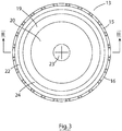
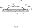
- the transport cap 13 is a removable transport cap 13 for sealing engagement with the top of the cup 2 and is configured to define a headspace chamber 25 between the sealing lid 5 and the transport cap 13 for receipt and retainment of fluid exiting the cup 2.
- the transport cap 13 is generally made from a polymer material such as PET (Polyethylene) or PS (Polystyrene), is opaque or coloured, and comprises a top panel 14 and a skirt 16 that extends downwardly from a periphery 15 of the top panel 14.
- the skirt comprises a series of fluted formations 17 which are conventional in friction fit lids for papers cups.
- the top panel 14 comprises a recessed annular sealing head 19 which defines a convex central part 20, and a second annular sealing head 22 at the periphery 15 of the top panel 14.
- a raised annular channel 24 is defined between the annular sealing heads 19 and 22.
- the convex central part 20 comprises a re-closable aperture 23 configured for receipt of a drinking straw.
- Figure 7 is a side elevational view of the transport cap 13 engaged with the cup 2 and sealing lid 5.
- Figures 8A and 8B are sectional views of the sealed container comprising cup 3, sealing lid 5 and transport cap 13 in an engaged configuration, which shows how the recessed annular sealing head 19 of the transport cap 13 is configured to abut and seal against the sealing lid 5, and peripherally define or form the headspace 25 defined between the sealing lid 5 and central convex part 20 of the transport cap 13.
- This illustration also shows how the second annular sealing head 22 is configured to abut and seal against the periphery 10 of the sealing lid 5 which is heat-welded to the annular surface 9 of the lip 4.
- the raised annular channel 24 defined between the sealing heads 19 and 22 which serves as a channel to collect any beverage which escapes beyond the sealing head 19 and prevent escape of the beverage.
- Figure 9 is a detailed view showing how the sealing lid 5 is welded to the annular surface 9 on the lip 4 of the cup 2.
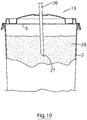
- Figure 10 illustrates the use of the carbonated beverage container of the invention, where a straw 26 with a piercing tip 27 is inserted through the re-closable aperture 23, and through the sealing lid 5, and into the beverage 28 contained within the container.
- Figure 11A and 11B are sectional views of the sealed container of Figure 7 showing how pressurised carbon dioxide 29 within the cup forces the sealing lid 5 upwards against the sealing heads 18 and 22, and how gas can escape through the pressure release aperture 6 in the sealing lid into the headspace 25 between the sealing lid and the transport cap ( Fig. 11A).
- Figure 11B shows how beverage 28 that escapes through the pressure release aperture 6 is maintained between the sealing lid and the transport cap by the annular sealing head 19.
- Figure 12 illustrates a method of packaging a carbonate beverage suitable for transport.
- a cup 3 is placed under the spout 30 of a carbonated beverage dispenser 31 of the type employed in fast-food outlets, and the dispenser is actuated to fill the cup with carbonated beverage 32 to a pre-set volume.
- the cup 3 containing the desired amount of carbonated beverage 32 is then moved to the welding machine 33 ( Fig. 12B ), where a welding head of the welding machine heat-welds a paper-PE laminate sealing lid 5 to the top of the cup, sealing the cup.
- a transport cap 13 is then placed on the top of the sealed cup and secured in place.
- the packaged beverage is then ready for transport.
- FIG 13 to 20 illustrate a welding machine and a use of the machine to seal a lid to a beverage cup.
- the welding machine 33 comprises a housing 35 comprising side walls 36 and a front wall 37 with an opening containing a cup holder tray 38 that is horizontally adjustable between a retracted and an extended position, cup-loading, position shown in Figure 13 .
- the cup holder tray 38 comprises an annular sealing head 40 defining an aperture for receipt of a paper cup 2 which is dimensioned such that when a cup is nested in the cup holder ( Fig. 13 ), a lip 4 of the cup 2 rests on the annular sealing head 40.
- the cup holder tray 38 additionally includes guide means for guiding a sealing lid 5 into position on the lip 4 of the cup 2.
- the guide means comprises three guide arms 41 positioned on the cup holder tray 38 equally spaced around the sealing head 40.
- Each guide arm comprises a lower part 42 that is substantially horizontal and an upper part 43 that is angled outwardly, whereby the combined action of the lower parts of the three guide arms acts to centre the lid directly above the annular sealing head 40.
- the welding machine 33 also includes a welding head (not shown) that is disposed in the machine above the cup holder tray 38 when it is in a retracted position, and vertically adjustable from a raised (resting) position to a lowered (welding) position.
- Figure 16 illustrates the cup 5 being filled with carbonated beverage by a drinks filling machine 45.
- Figure 17 illustrates the welding machine 33 with the cup holder tray 38 in a retracted position inside the housing 35 and the welding head 47 in a raised, resting, position.
- Figure 18 illustrates the welding machine 33 with the cup holder tray 38 in an extended position outside of the housing 35, and a cup 5 nested in the cup holder tray 38 and a sealing lid 5 positioned above the cup and guide arms 41 and about to be dropped on to the top of the cup where the guide arms serve to correctly position the sealing lid on the lip of the cup as described previously.
- Figure 19 illustrates a heat-welding step, showing the cup holder tray 38 in a retracted position within the housing, under the welding head which is 47 is a lowered into a welding position, abutting the annular sealing head 40 and heat-welding the paperboard lid 5 to the lip 4 of the paperboard cup 2.
- Figures 20A to 20C are plan views of the cup holder tray 38 in an extended position outside of the housing, prior to loading of the cup ( Fig. 20A ), after loading of the paper cup 2 ( Fig. 20B ) and showing the sealing lid 5 about to be placed on the cup 2 guided by the guide arms (not shown), and after the paper cup 5 has been guided onto the lip 4 of the cup 2 and the tray has been retracted into the housing 35 ( Fig. 20C ).
- Example 2 The same containers as employed in Example 1 were subjected to a pressure test.
- the first container contained a micron-sized aperture (0.60 +/- 0.02 mm) in the centre of the paperboard laminate sealing lid 5, and the second container did not contain an aperture in the sealing lid.
- Steadily increasing pressure was applied to both containers.
- the seal in the first container remained intact up to a pressure of 0,19 +/- 0.014 bar (2.8 +/- 0.2 psi) whereupon the application of further pressure failed to register pressure increases in the container, indicating that the pressure was being vented through the micron-sized aperture at elevated pressure levels, preventing loss of integrity in the seal.
- the seal in the first container remained intact up to a pressure of 0,21 +/- 0.014 bar (3.0 +/- 0.2 psi) and pressure beyond this value caused the sealed rim of the container to fail.
Landscapes
- Engineering & Computer Science (AREA)
- Mechanical Engineering (AREA)
- Chemical & Material Sciences (AREA)
- Ceramic Engineering (AREA)
- Composite Materials (AREA)
- Health & Medical Sciences (AREA)
- Nutrition Science (AREA)
- Life Sciences & Earth Sciences (AREA)
- Food Science & Technology (AREA)
- Polymers & Plastics (AREA)
- Closures For Containers (AREA)
Description
- The present invention relates to sealed containers for pressurised beverages, a kit for assembling a sealed container containing a pressurised beverage as well as a method of providing a sealed container containing a beverage.
- Most fast-food outlets sell carbonated beverages in paper cups with plastic friction-fit lids having an aperture for receipt of a straw. As the drinks are generally consumed in the store, or carried out by a user, the current cups and lids do not have to be leak proof and/or tamper evident. More recently, the large fast-food outlets are providing a home delivery services, which involves meals being specially packaged and delivered to a consumer's home. The transport of the beverages presents a challenge, as the drinks are subjected to a considerable amount of movement when they are transported, which is particularly problematical in the case of carbonated drinks which are pressurised and evolve carbon dioxide when disturbed, shaken and exposed to heat. The use of conventional friction-fit lids is unsuitable as the seal is insufficient to maintain pressure in the cup, meaning that the beverage goes "flat", and the friction-fit lids detach easily making them entirely unsuitable as a home-delivery solution. Currently, PET bottles with a screw-cap are employed for home delivery of carbonated beverages. The problem with PET bottles is that they are more expensive than in-store cup options, they require refrigeration, they require a lot more storage space, and the introduces a lot of plastic material into the environment.
-
EP 0 896 930US 2015/274367 andWO 2010/135613 disclose containers manufactured from paperboard. - It is an object of the invention to overcome at least one of the above-referenced problems.
- According to a first aspect of the present invention, there is provided a kit for assembling a sealed container containing a beverage, the kit comprising:
- a cup with an open top and a lip circumscribing the open top;
- a sealing lid dimensioned to be welded to the lip of the cup continuously around the lip to seal the cup; a removable transport cap for sealing engagement with the top of the cup configured to define
- a headspace chamber between the sealing lid and the transport cap for receipt and retainment of excess fluid exiting the cup and a welding machine comprising a welding head configured for sealing the paperboard cap to the lip of the cup,
- characterised in that the beverage is a pressurised beverage, the cup is a paperboard cup and the sealing lid is a paperboard sealing lid including a pressure release aperture wherein in use a beverage can be dispensed into the cup, and the welding machine can be actuated whereby the welding head can weld the paperboard sealing lid to the lip of the cup continuously around the lip to provide the sealed container containing the beverage.
- According to another aspect of the present invention, there is provided a sealed container containing a beverage, the sealed container comprising:
- a cup with an open top and a lip circumscribing the open top;
- a beverage disposed within the cup;
- a sealing lid welded to the lip of the cup continuously around the lip to seal the cup, and a removable transport cap for sealing engagement with the top of the cup configured to define a headspace chamber between the sealing lid and the transport cap for receipt and retainment of excess fluid exiting the cup characterised in that the beverage is a pressurised beverage, the cup (2) is a paperboard cup (2) and the sealing lid (5) is a paperboard sealing lid (5) including a pressure release aperture (6).
- The pressure release aperture provides limited fluid communication through the lid. In one embodiment, the pressure release aperture has an area of about 0.1 mm2 to about 10 mm2. Optionally, the pressure release aperture is a micron-sized pressure release aperture. Suitably, the micron-sized pressure release aperture has an area of about 0.05 mm2 to about 0.8 mm2.
- Suitably, the pressure release aperture is positioned about the centre of the sealing lid.
- In one embodiment, the paperboard cup and paperboard sealing lid are formed of the same paperboard material. Preferably, the paperboard material is a paperboard-polyethylene laminate.
- In one embodiment, the transport cap comprises a top panel having a raised central portion and the headspace chamber is defined between the sealing lid and the raised central portion.
- Preferably, the top panel includes a first annular sealing head configured to abut the paperboard sealing lid when the transport cap is engaged on the top of the cup to peripherally define the headspace chamber.
- In a preferred embodiment, the top panel includes a second annular sealing head at the periphery of the top panel.
- Preferably, the top panel of the transport cap comprises a raised annular channel defined by the first annular sealing head and the peripheral annular sealing head. Optionally, the top panel of the transport cap comprises an opening, or means for providing an opening, for receipt of a drinking straw.
- In one embodiment, the welding machine is a heat-welding machine.
- Suitably, the paperboard lid comprises only one pressure release aperture.
- The cup and sealing lid comprise paperboard, for example a paperboard laminate material (i.e. a laminate of paperboard and at least one of a polymer or foil layer).
- The problems of the prior art are addressed by the provision of paperboard cups for carbonated beverages that are sealed using paperboard lids that are heat welded to the cup. The use of a paperboard lid with a paperboard cup provides for a seal that has been shown to withstand the high pressures that carbonated beverages generate without compromising the integrity of the seal. The kit and container of the invention are especially applicable for use with "ready to consume" and "short shelf-life drinks" such as carbonated beverages sold in fast-food outlets which are pressurised and tends to lose their fizziness rapidly over time. In addition, the Applicant has discovered that the provision of a small aperture in the cap allows venting of a sufficient volume of carbon dioxide to prevent the seal rupturing during transport, without risk of losing significant amounts of beverage or contaminating other food items being delivered at the same time. The micron-sized aperture has also been found to allow the lid be pierced with a plastic drinking straw, as the area of the lid around the micron-sized has been found to become weakened during transport due to beverage wetting the area of the lid around the aperture. Also provided is an outer transport cap comprising an annular sealing head configured to abut the sealing lid when the outer transport cap is engaged with the cup, which serves to retain any beverage that may have leaked through the micron-sized aperture under extreme agitation / disturbance at the centre of the lid and away from the periphery where it is prone to leakage. The paperboard sealing lid creates an airtight seal on the container body which creates a pressurised area between the beverage and the sealing lid inside the vessel/container that holds the liquid in place to prevent leakage out through the micron-sized aperture.
- The sealing lid also functions as a tamper evident seal, which serves to provide comfort to the consumer that the drink they are about to consume has not been tampered with or adulterated in any way. Also, the paperboard nature of the sealing lid allows material to be printed on the lid that is visible by the consumer, for example branding, product information, or marketing information or advertising.
- In one embodiment, the micron-sized pressure release aperture has an area of about 0.05 to 0.8 mm2. In one embodiment, the micron-sized pressure release aperture has an area of about 0.1 to 0.6 mm2. In one embodiment, the micron-sized pressure release aperture has an area of about 0.2 to 0.4 mm2. In one embodiment, the micron-sized pressure release aperture has an area of about 0.3 mm2.
- In one embodiment, the pressure release aperture is positioned at or about the centre of the sealing lid. This is intended to remove any alignment issues when a straw is used to pierce the sealing lid by passing the straw through the aperture in the transport cap. If it was anywhere else on the sealing lid then the sealing cap would have to be specifically aligned to get the straw through the cap in the correct location to hit the aperture on the sealing lid. In one embodiment, the sealing lid comprises a plurality of micron-sized apertures, for example ten, eight, six, four or three. In one embodiment, the sealing lid may comprise only one or two micron-sized apertures.
- In one embodiment, the paperboard cup and paperboard sealing lid are formed of the same material.
- In one embodiment, the paperboard cup and paperboard sealing lid are formed of a paperboard-polymer laminate. Use of paperboard polymer laminates is preferred, as it has been shown to provide a very secure seal. Laminates of paperboard and other materials may also be employed, for example paperboard-metallic film laminates.
- In one embodiment, the paperboard cup and paperboard sealing lid are formed of a paperboard-polyethylene laminate. Other paperboard-polymer may be employed as described below.
- In a preferred embodiment, the paperboard sealing lid is heat welded to the lip of the cup. In this embodiment, both the cup and lid will generally include a polymer layer which bond together during heat welding. Heat welding machines are of a suitable size for use in fast-food outlets, and therefore paperboard-polymer cups and sealing lids that can be heat-welded are most suitable for the present invention.
- In an embodiment in which the cup and sealing lid comprise a paperboard-metallic film laminate, induction welding may be employed to seal the sealing lid to the cup. Induction welding is described in the literature, for example Davies et al (Induction Heating Handbook, McGraw-Hill, ISBN 0-07-084515-8).
- In one embodiment, the cup has a double wall. This facilitates keeping the carbonated beverage cool, which reduces the rate of pressure increase in the cup during transport, and thereby reduces the pressure on the seal.
- In one embodiment, the cup and/or sealing lid are each, independently, formed from a biodegradable or compostable material. Examples of biodegradable and compostable paperboard laminate material include bioactive thermoplastic Poly(lactic acid) / polylactic acid / polylactide (PLA).
- In one embodiment, the container or kit comprises a removable transport cap configured for friction-fit engagement with the top of the cup on the sealing lid, the transport cap having a top panel and a skirt circumscribing the top panel, in which the top panel includes a first annular sealing head configured to abut the paperboard lid when the transport cap is engaged on the top of the cup. The annular sealing head provides an annular seal between the paperboard sealing lid and transport cap that retains leaked beverage, typically at the centre of the lid away from the periphery.
- In one embodiment, the top panel comprises a raised central portion defined by the first annular sealing head configured to provide headspace between the sealing lid and the transport cap that is in fluid communication with the micron-sized aperture. In one embodiment, the raised central portion is generally convex.
- In one embodiment, the top portion of the transport cap comprises a peripheral annular sealing head configured to abut a periphery of the paperboard sealing lid when the transport cap is engaged on the top of the cup. The provision of a second (peripheral) sealing head provides a second barrier to beverage leaking out the side of the transport cap.
- In one embodiment, the transport cap is formed from a polymer material, for example polyethylene terephthalate (PET). Other materials include polylactide (PLA), High Impact Polystyrene (HIPS), Polypropylene (PP).
- In one embodiment, the top portion of the transport cap comprises a raised annular portion defined by the first annular sealing head and the peripheral annular sealing head. This provides a retaining space for beverage that has leaked out of the micron-sized aperture and past the first annular sealing head.
- In one embodiment, the top panel of the transport cap comprises an opening for receipt of a drinking straw, or means for making an aperture (for example crossed-slits, or a frangible or weakened portion of the lid).
- In one embodiment, the paperboard sealing lid comprises a tab portion that extends beyond the lip of the cup for use in removal of the sealing lid from the cup. In other embodiments, the container is not configured for removal of the sealing lid, and in this embodiment, the user is generally directed to pierce a hole in the sealing lid with a straw or the like. The Applicant has discovered that the use of a micron-sized pressure release aperture at the centre of the lid provides an area of the lid that is weakened due to coming into contact with beverage, and therefore suitable for rupturing with a straw.
- In one embodiment, the paperboard sealing lid comprises a frangible or weakened portion, or aperture, configured for receipt of a drinking spout. This is particularly useful when the beverage is a hot drink, such as coffee or tea, where a drinking straw is not suitable.
- In one embodiment, the skirt comprises formations configured to friction-fit over the lip of the cup, to secure the transport cap to the cup. In one embodiment, the formations are spaced apart fluting formations that circumscribe the skirt of the lid. Such formations and friction-fit configurations are well known in the art, for example from
US3583596 . - In one embodiment, the container comprises a pressurised beverage, for example a carbonated beverage. Examples include sparkling water, cola, orange, lemon and lime, lemonade, beer, tonic water, cider, and sparkling wine. The container of the invention may also be employed for other beverages that generate gas.
- The container, or kit, may include a drinking spout configured to penetrate the sealing lid for the purpose of drinking the beverage.
- In an example not according to the invention the disclosure describes a transport cap for a sealed beverage container of the type having an open top, a lip circumscribing the open top, and a sealing lid welded to the lip, the transport cap having a top panel and a skirt circumscribing the top panel, in which the top panel includes a first annular sealing head configured to abut the sealing lid when the transport cap is engaged on the top of the cup.
- In one example the top panel comprises a raised central portion defined by the first annular sealing head configured to provide a chamber for receipt of fluid exiting the cup.
- In one example the top portion of the transport cap comprises a peripheral annular sealing head configured to abut a periphery of the sealing lid when the transport cap is engaged on the top of the cup.
- In one example, the top portion of the transport cap comprises a raised annular portion defined by the first annular sealing head and the peripheral annular sealing head.
- In one example, the top panel of the transport cap-comprises an opening for receipt of a drinking straw, or means for making an aperture (for example crossed-slits, or a frangible or weakened portion of the lid).
- In an example not according to the invention the disclosure describes a method of preparing a beverage suitable for the ready-to-drink market including home delivery comprising the steps of:
- dispensing a beverage into a paperboard cup with an open top and a lip circumscribing the open top;
- welding a paperboard sealing lid to the lip of the open top of the cup to seal the cup; and attaching a removable transport cap to the top of the cup covering the paperboard sealing lid to define a headspace chamber between the sealing lid and the transport cap for receipt and retainment of excess fluid exiting the cup.
- Preferably, the sealing lid optionally comprises a pressure release aperture providing pressure regulation within the cup. Optionally, the pressure release aperture is a micron-sized pressure release aperture.
- Preferably, the removable transport cap is configured for sealing engagement with the top of the cup and has a top panel and a skirt circumscribing the top panel, in which the top panel includes a first annular sealing head configured to abut the paperboard sealing lid (5) when the transport cap is engaged on the top of the cup.
- In one example, the paperboard sealing lid is heat welded to the lip of the cup
- In one example, the method includes a step of attaching a transport cap according to the invention to the cup on top of the paperboard sealing lid.
- In another embodiment, the invention also extends to a method of providing a sealed container containing a beverage, the method comprising the steps of:
- providing a cup with an open top and a lip circumscribing the open top;
- dispensing a beverage into the cup;
- welding a sealing lid to the lip of the cup continuously around the lip to seal the cup; and attaching a removable transport cap to the top of the cup covering the sealing lid to define a headspace chamber between the sealing lid and the transport cap for receipt and retainment of fluid exiting the cup. characterised in that the beverage is a pressurised beverage, the cup is a paperboard cup and the sealing lid is a paperboard sealing lid including a pressure release aperture. Preferably, the removable transport cap is configured for sealing engagement with the top of the cup and has a top panel and a skirt circumscribing the top panel, in which the top panel includes a first annular sealing head configured to abut the paperboard sealing lid when the transport cap is engaged on the top of the cup.
- In an example not according to the invention the disclosure describes a welding machine for welding a lid to a cup containing a beverage to seal the beverage in the cup, the welding machine comprising a housing having:
- a cup holder having an annual sealing head defining an aperture for receipt of a cup and configured for nested engagement with a lip of the cup when the cup is placed in the cup holder; and
- a welding head configured for movement between a first position in which the welding head is spaced apart from the sealing head and a welding position in which the welding head abuts the annular sealing head,
- wherein the cup holder comprises guide means for guiding the correct placement of the lid onto the lip of the cup.
- In one example, the guide means comprises a plurality of guide arms disposed around the welding head. In one embodiment, guide means comprises at least 3 guide arms, for example 3, 4, 5, or 6.
- In one example, each guide arm has a lower part that is substantially vertical and an upper part that outwardly angled.
- In one example, the cup holder is configured for horizontal movement between a welding position in which the cup holder is positioned within the housing and the welding head is positioned above the annular sealing head, and a cup mounting position in which the cup holder is presented outside of the housing.
- In a further example not according to the invention the disclosure describes a method of providing a sealed container containing a beverage, the method comprising the steps of:
- providing a paperboard cup with an open top and a lip circumscribing the open top;
- dispensing a beverage into the cup;
- welding a paperboard sealing lid to the lip of the cup continuously around the lip to seal the paperboard cup; and
- optionally, attaching a removable transport cap to the top of the cup covering the paperboard sealing lid.
- In one variation of this example, the removable transport cap is configured for sealing engagement with the top of the cup and has a top panel and a skirt circumscribing the top panel, in which the top panel includes a first annular sealing head configured to abut the paperboard sealing lid when the plastic cap is engaged on the top of the cup. Typically, the beverage is a carbonated beverage.
- Other aspects and preferred embodiments of the invention are defined and described in the claims set out below.
-
-
Figure 1 is a perspective view of a container for carbonated beverages according to an a embodiment of the invention; -
Figure 2 is an exploded view of the container ofFigure 1 -
Figure 3 is a top view of the transportation cap; -
Figure 4 is a side elevational view of the transportation cap; -
Figure 5 is a perspective view of the transportation cap; -
Figure 6 is a sectional side view of the transportation cap taken along the lines III-III ofFigure 3 ; -
Figure 7 is a side elevational view of the container ofFigure 1 with a transportation cap mounted on the cup; -
Figure 8A is a sectional side view of the container taken ofFigure 7 , andFigure 8B is a detail ofFigure 8A ; -
Figure 9 is a sectional side view of part of the cup and paperboard sealing lid ofFigure 1 ; -
Figure 10 is a partly sectional elevational view of the container of the invention in use with a straw; -
Figure 11A and Figure 11B are sectional view of the container and lid ofFigure 7 showing how pressurised carbon dioxide within the cup can escape through the pressure release aperture in the paperboard sealing lid into the headspace between the sealing lid and the transport cap (Fig. 11A ), and showing how any beverage that escapes through the pressure release aperture is maintained between the cap and the lid by the annular sealing head (Fig. 11B ) -
Figure 12 is an illustration of a method of packaging a carbonate beverage suitable for the ready-to-drink/home delivery market. -
Figure 13 is a perspective view of a welding machine, showing a paperboard cup containing a beverage placed in the cup holder and a paperboard lid positioned above the top of the cup above the guide arms. -
Figure 14 is a perspective view of a welding machine ofFigure 13 , showing the cup holder without the cup in place. -
Figure 15 is top plan view of part of the cup holder showing the sealing head and guide arms. -
Figure 16 is a front elevational view of a cup being filled with a beverage in a beverage filling machine. -
Figure 17 is a front plan view of a welding machine. -
Figure 18 is a side elevational view the welding machine ofFigure 17 (with a side wall of the housing removed) showing the cup holder projecting out of the housing and a cup nested in the cup holder and a cap positioned above the lip of the cup. -
Figure 19 is the same side elevational view asFigure 18 with the cup holder retracted into the housing and the welding head lowered into the welding position. -
Figure 20A is a top plan view of the cup holder in an extended position prior to loading a cup. -
Figure 20B is the same view of the cup holder asFigure 20A shown with a cup containing a beverage nested in the cup holder, and a lid. -
Figure 20C is the same view of the cup holder asFigure 20B shown with the lid in position on the top of the cup. - Where used herein and unless specifically indicated otherwise, the following terms are intended to have the following meanings in addition to any broader (or narrower) meanings the terms might enjoy in the art:
Unless otherwise required by context, the use herein of the singular is to be read to include the plural and vice versa. The term "a" or "an" used in relation to an entity is to be read to refer to one or more of that entity. As such, the terms "a" (or "an"), "one or more," and "at least one" are used interchangeably herein. - As used herein, the term "comprise," or variations thereof such as "comprises" or "comprising," are to be read to indicate the inclusion of any recited integer (e.g. a feature, element, characteristic, property, method/process step or limitation) or group of integers (e.g. features, element, characteristics, properties, method/process steps or limitations) but not the exclusion of any other integer or group of integers. Thus, as used herein the term "comprising" is inclusive or open-ended and does not exclude additional, unrecited integers or method/process steps.
- As used herein, the term "carbonated beverage" refers to carbonated drinks like cola, orange, lemonade, lemon and lime, water, and other "fizzy drinks". However, it will be appreciated that the container and methods of the invention may be employed with other pressurised drinks, such as beer, cider, sparkling water and sparkling wine. In one embodiment, the beverage is a "ready to consume" beverage, especially a "short shelf life" beverage.
- As used herein, the term "micron-sized pressure release aperture" refers to an aperture that is sufficiently small to keep liquid within the cup when the cup is shaken or falls over, yet allow a sufficient amount of pressure dissipate out of the cup to prevent rupturing of the lid during period of pressure build-up. Generally, an aperture having an area of about 0.05 to about 0.8 mm2 are suitable for this purpose, although this depends on the viscosity of the beverage. In a preferred embodiment, the aperture has an area of about 0.1 to 0.6 mm2, more preferably about 0.2 to about 0.4 mm2.
- As used herein, the term "paperboard" as applied to paperboard cups and paperboard sealing lids refers to paperboard materials conventionally used in carbonated beverage cups, including paperboard-polymer laminates and paperboard-foil laminates. In a preferred embodiment, the paperboard laminate is a paperboard-polymer laminate, as these have been found to provide the best seal when adhered together by welding, generally heat welding. These paperboard polymer laminates generally include a layer of paperboard with a barrier layer of polymer, generally a polyethylene polymer, on one or both sides of the paper. Specific examples of paperboard laminates for use in containers of the invention include Stora Enso's Cupforma paperboard, Georgia Pacific's CPH Masterserve cupstock,, Mondi Paper Miprotex Barrier Stock. Paperboard formed from any type of paper pulp may be employed, including conventional paperpulp from trees, or paperpulp from bamboo or bagasse.
- As used herein, the term "adhered" as applied to the sealing lids and cups refers to the sealing of the lid to the lip of the cup. Various methods of sealing may be employed, for example by means of welding (i.e. induction, heat and ultrasound welding methodologies). Heat welding has been found to provide the most efficient seal between a paperboard sealing lid and paperboard cup, capable of resisting significant pressure build-up in the cup during transport and storage, while providing a material that can be easily ruptured with a straw to allow the beverage be consumed.
- As used herein, the term "heat welded" (also referred to as "heat-fused") refers to a process where the lip is welded to the lip of the cup using heat. Methods of heat welding paperboard laminate materials together are well known to those skilled in the art, and machines for this purpose are commercially available. Welding of the lid to the lip on the cup is facilitated by providing a lip with a flattened upper surface, which increases the surface area of the lip available for welding to the lid.
- The invention will now be described with reference to specific Examples. These are merely exemplary and for illustrative purposes only: they are not intended to be limiting in any way to the scope of the monopoly claimed or to the invention described. These examples constitute the best mode currently contemplated for practicing the invention.
- Referring to the drawings, and initially to
Figures 1 and2 , there is illustrated a container for a carbonated beverage according to the invention, indicated generally by thereference numeral 1. The container comprises a paperboard laminate cup 2 (hereafter "cup") having an open top 3 circumscribed by a lip 4 (Fig. 1 ), and a paperboardlaminate sealing lid 5 that is heat-welded to the lip to seal the cup 2 (Fig. 2 ). The paperboard laminate sealing lid 5 (hereafter "sealing lid" has a single micron-sizedpressure release aperture 6 disposed in the centre of the lid having a diameter of approximately 0.6 mm. - In more detail, the sealing lid and cup are formed from the same paperboard-polyethylene laminate material, specifically PE coated Paper Cup Stock. Other paperboard-polymer laminates that may be employed include Biodegradable PLA Coated Paper Cup Stock. The cup is generally frusto-connical in shape, has a volume of approximately 450 mls (16 oz), and has an
upper section 2A that is double walled and alower section 2B that is single walled. Thelip 4 at the top of the cup extends laterally outwardly of the top of the cup and a top of the lip is flattened to provide anannular landing surface 9 having a width of about 5 mm to which aperiphery 10 of thepaperboard sealing lid 5 is heat welded. - In use, a carbonated beverage is dispensed into the cup from a drink dispenser to a pre-set volume, and the cup containing the beverage is placed in a heat-welding machine, where a sealing lid is welded to the annular surface of the lip of the cup. This provides a very strong seal that is capable of withstanding pressures in the cup of up to 3 Bar. In addition, the provision of the micron-sized aperture in the sealing lid allows a certain amount of pressure to be vented from the cup during periods of pressure build-up, for example during transport, which helps prevent rupturing of the seal.
- Referring to
Figs 3 to 6 , there is illustrated a transport cap suitable for use with a sealed container of the invention and indicated generally by thereference numeral 13. As shall be explained more fully below, thetransport cap 13 is aremovable transport cap 13 for sealing engagement with the top of thecup 2 and is configured to define aheadspace chamber 25 between the sealinglid 5 and thetransport cap 13 for receipt and retainment of fluid exiting thecup 2. Thetransport cap 13 is generally made from a polymer material such as PET (Polyethylene) or PS (Polystyrene), is opaque or coloured, and comprises atop panel 14 and askirt 16 that extends downwardly from aperiphery 15 of thetop panel 14. The skirt comprises a series offluted formations 17 which are conventional in friction fit lids for papers cups. Thetop panel 14 comprises a recessedannular sealing head 19 which defines a convexcentral part 20, and a secondannular sealing head 22 at theperiphery 15 of thetop panel 14. A raisedannular channel 24 is defined between the annular sealing heads 19 and 22. The convexcentral part 20 comprises are-closable aperture 23 configured for receipt of a drinking straw. -
Figure 7 is a side elevational view of thetransport cap 13 engaged with thecup 2 and sealinglid 5. -
Figures 8A and 8B are sectional views of the sealedcontainer comprising cup 3, sealinglid 5 andtransport cap 13 in an engaged configuration, which shows how the recessedannular sealing head 19 of thetransport cap 13 is configured to abut and seal against the sealinglid 5, and peripherally define or form theheadspace 25 defined between the sealinglid 5 and centralconvex part 20 of thetransport cap 13. This illustration also shows how the secondannular sealing head 22 is configured to abut and seal against theperiphery 10 of the sealinglid 5 which is heat-welded to theannular surface 9 of thelip 4. Also shown is the raisedannular channel 24 defined between the sealing heads 19 and 22 which serves as a channel to collect any beverage which escapes beyond the sealinghead 19 and prevent escape of the beverage.Figure 9 is a detailed view showing how the sealinglid 5 is welded to theannular surface 9 on thelip 4 of thecup 2. -
Figure 10 illustrates the use of the carbonated beverage container of the invention, where astraw 26 with a piercingtip 27 is inserted through there-closable aperture 23, and through the sealinglid 5, and into thebeverage 28 contained within the container. -
Figure 11A and 11B are sectional views of the sealed container ofFigure 7 showing howpressurised carbon dioxide 29 within the cup forces the sealinglid 5 upwards against the sealing heads 18 and 22, and how gas can escape through thepressure release aperture 6 in the sealing lid into theheadspace 25 between the sealing lid and the transport cap (Fig. 11A). Figure 11B shows howbeverage 28 that escapes through thepressure release aperture 6 is maintained between the sealing lid and the transport cap by theannular sealing head 19. -
Figure 12 illustrates a method of packaging a carbonate beverage suitable for transport. In a first step (Fig. 12A ), acup 3 is placed under thespout 30 of acarbonated beverage dispenser 31 of the type employed in fast-food outlets, and the dispenser is actuated to fill the cup withcarbonated beverage 32 to a pre-set volume. Thecup 3 containing the desired amount ofcarbonated beverage 32 is then moved to the welding machine 33 (Fig. 12B ), where a welding head of the welding machine heat-welds a paper-PElaminate sealing lid 5 to the top of the cup, sealing the cup. Atransport cap 13 is then placed on the top of the sealed cup and secured in place. The packaged beverage is then ready for transport. -
Figure 13 to 20 illustrate a welding machine and a use of the machine to seal a lid to a beverage cup. Referring toFigures 13-15 , thewelding machine 33 comprises ahousing 35 comprisingside walls 36 and afront wall 37 with an opening containing acup holder tray 38 that is horizontally adjustable between a retracted and an extended position, cup-loading, position shown inFigure 13 .Referring toFigure 14 , thecup holder tray 38 comprises anannular sealing head 40 defining an aperture for receipt of apaper cup 2 which is dimensioned such that when a cup is nested in the cup holder (Fig. 13 ), alip 4 of thecup 2 rests on theannular sealing head 40. Thecup holder tray 38 additionally includes guide means for guiding a sealinglid 5 into position on thelip 4 of thecup 2. The guide means comprises three guidearms 41 positioned on thecup holder tray 38 equally spaced around the sealinghead 40. Each guide arm comprises alower part 42 that is substantially horizontal and anupper part 43 that is angled outwardly, whereby the combined action of the lower parts of the three guide arms acts to centre the lid directly above theannular sealing head 40. Thewelding machine 33 also includes a welding head (not shown) that is disposed in the machine above thecup holder tray 38 when it is in a retracted position, and vertically adjustable from a raised (resting) position to a lowered (welding) position. - Referring to
Figures 16 to 19 , the use of the welding machine to heat-weld apaperboard sealing lid 5 to apaperboard cup 2 is described, in which parts identified with reference to the previous embodiments are assigned the same reference numerals. -
Figure 16 illustrates thecup 5 being filled with carbonated beverage by adrinks filling machine 45. -
Figure 17 illustrates thewelding machine 33 with thecup holder tray 38 in a retracted position inside thehousing 35 and thewelding head 47 in a raised, resting, position. -
Figure 18 illustrates thewelding machine 33 with thecup holder tray 38 in an extended position outside of thehousing 35, and acup 5 nested in thecup holder tray 38 and a sealinglid 5 positioned above the cup and guidearms 41 and about to be dropped on to the top of the cup where the guide arms serve to correctly position the sealing lid on the lip of the cup as described previously. -
Figure 19 illustrates a heat-welding step, showing thecup holder tray 38 in a retracted position within the housing, under the welding head which is 47 is a lowered into a welding position, abutting theannular sealing head 40 and heat-welding thepaperboard lid 5 to thelip 4 of thepaperboard cup 2. -
Figures 20A to 20C are plan views of thecup holder tray 38 in an extended position outside of the housing, prior to loading of the cup (Fig. 20A ), after loading of the paper cup 2 (Fig. 20B ) and showing the sealinglid 5 about to be placed on thecup 2 guided by the guide arms (not shown), and after thepaper cup 5 has been guided onto thelip 4 of thecup 2 and the tray has been retracted into the housing 35 (Fig. 20C ). - 473ml (16oz) cups formed of a paperboard-PE laminate material were filled with carbonated beverage and a paperboard-PE laminate sealing lid was heat-sealed to the lip of the cup using a table top, single cavity cup heat sealing semi-automatic machine. A transport cap was then placed on the top of the cup and secured in place. The cup was then dropped 1,22 meter (4 feet) onto a concrete surface without any loss of integrity in the heat weld between the cup and the lid, and without any spillage of beverage.
- The same containers as employed in Example 1 were subjected to a pressure test. The first container contained a micron-sized aperture (0.60 +/- 0.02 mm) in the centre of the paperboard
laminate sealing lid 5, and the second container did not contain an aperture in the sealing lid. Steadily increasing pressure was applied to both containers. The seal in the first container remained intact up to a pressure of 0,19 +/- 0.014 bar (2.8 +/- 0.2 psi) whereupon the application of further pressure failed to register pressure increases in the container, indicating that the pressure was being vented through the micron-sized aperture at elevated pressure levels, preventing loss of integrity in the seal. The seal in the first container remained intact up to a pressure of 0,21 +/- 0.014 bar (3.0 +/- 0.2 psi) and pressure beyond this value caused the sealed rim of the container to fail. This demonstrates that the pressure release aperture functions to vent gas from the cup at elevated pressure, preventing the pressure rising to a level that causes a loss of integrity in the seal.
Claims (10)
- A kit for assembling a sealed container containing a beverage, the kit comprising:a cup (2) with an open top (3) and a lip (4) circumscribing the open top;a sealing lid (5) dimensioned to be welded to the lip of the cup continuously around the lip to seal the cup; a removable transport cap (13) for sealing engagement with the top of the cup (2) configured to define a headspace chamber (25) between the sealing lid (5) and the transport cap (13) for receipt and retainment of fluid exiting the cup (2) and a welding machine (33) comprising a welding head configured for sealing the paperboard sealing lid to the lip of the cup,characterised in that the beverage is a pressurised beverage, the cup (2) is a paperboard cup (2) and the sealing lid (5) is a paperboard sealing lid (5) including a pressure release aperture (6) wherein in use a beverage can be dispensed into the cup, and the welding machine can be actuated whereby the welding head can weld the paperboard sealing lid to the lip of the cup continuously around the lip to provide the sealed container containing the beverage.
- A kit as claimed in Claim 1 , in which the pressure release aperture has an area of about 0.1 mm2 to about 10 mm2.
- A kit as claimed in Claim 1, in which the pressure release aperture (6) is a micron-sized pressure release aperture (6) having an area of about 0.05 mm2 to about 0.8 mm2.
- A kit according to any preceding Claim, in which the transport cap (13) comprises a top panel (14) having a raised central portion (20) and the headspace chamber (25) is defined between the sealing lid (5) and the raised central portion (20).
- A kit according to Claim 4, in which the top panel (14) includes a first annular sealing head (19) configured to abut the paperboard sealing lid (5) when the transport cap (13) is engaged on the top of the cup to peripherally define the headspace chamber (25).
- A sealed container containing a beverage, the sealed container comprising:a cup (2) with an open top (3) and a lip (4) circumscribing the open top;a beverage (32) disposed within the cup;a sealing lid (5) welded to the lip of the cup continuously around the lip to seal the cup; anda removable transport cap (13) for sealing engagement with the top of the cup (2) configured to define a headspace chamber (25) between the sealing lid (5) and the transport cap (13) for receipt and retainment of fluid exiting the cup (2) characterised in that the beverage is a pressurised beverage, the cup (2) is a paperboard cup (2) and the sealing lid (5) is a paperboard sealing lid (5) including a pressure release aperture (6).
- A sealed container as claimed in Claim 6, in which the pressure release aperture (6) has an area of about 0.1 mm2 to about 10 mm2.
- A sealed container as claimed in Claim 6 , in which the pressure release aperture (6) is a micron-sized pressure release aperture (6) having an area of about 0.05 mm2 to about 0.8 mm2.
- A sealed container according to any of Claims 6 to 8, in which the transport cap (13) comprises a top panel (14) having a raised central portion (20) and the headspace chamber (25) is defined between the sealing lid (5) and the raised central portion (20) and, optionally, the top panel (14) includes a first annular sealing head (19) configured to abut the paperboard sealing lid (5) when the transport cap (13) is engaged on the top of the cup to peripherally define the headspace chamber (25).
- A method of providing a sealed container containing a beverage, the method comprising the steps of:providing a cup (2) with an open top (3) and a lip (4) circumscribing the open top;dispensing a beverage (32) into the cup;welding a sealing lid (5) to the lip of the cup continuously around the lip to seal the cup; andattaching a removable transport cap (13) to the top of the cup (2) covering the sealing lid to define a headspace chamber (25) between the sealing lid (5) and the transport cap (13) for receipt and retainment of fluid exiting the cup (2) characterised in that the beverage is a pressurised beverage, the cup (2) is a paperboard cup (2) and the sealing lid (5) is a paperboard sealing lid (5) including a pressure release aperture (6).
Applications Claiming Priority (2)
| Application Number | Priority Date | Filing Date | Title |
|---|---|---|---|
| GB1808094.5A GB2573806A (en) | 2018-05-18 | 2018-05-18 | A sealed container for beverages |
| GB1903043.6A GB2581997A (en) | 2019-03-07 | 2019-03-07 | A sealed container for beverages |
Publications (2)
| Publication Number | Publication Date |
|---|---|
| EP3569112A1 EP3569112A1 (en) | 2019-11-20 |
| EP3569112B1 true EP3569112B1 (en) | 2021-03-17 |
Family
ID=66589368
Family Applications (1)
| Application Number | Title | Priority Date | Filing Date |
|---|---|---|---|
| EP19174977.9A Active EP3569112B1 (en) | 2018-05-18 | 2019-05-16 | A sealed container for beverages |
Country Status (7)
| Country | Link |
|---|---|
| US (1) | US20210214135A1 (en) |
| EP (1) | EP3569112B1 (en) |
| AU (1) | AU2019270429B2 (en) |
| CA (1) | CA3100110A1 (en) |
| ES (1) | ES2880484T3 (en) |
| MX (1) | MX2020012260A (en) |
| WO (1) | WO2019219856A1 (en) |
Families Citing this family (8)
| Publication number | Priority date | Publication date | Assignee | Title |
|---|---|---|---|---|
| RU196405U1 (en) * | 2019-12-27 | 2020-02-28 | Дмитрий Сергеевич Расторгуев | DISPOSABLE GLASS FOR HOT AND COOLED DRINKS |
| EP4122834B1 (en) * | 2020-03-16 | 2025-12-10 | Yakult Honsha Co., Ltd. | Heat-sealing device |
| WO2021191491A1 (en) * | 2020-03-25 | 2021-09-30 | Dolea Oy | A disposable fibre-based lid and a lid apparatus |
| AU2021270555A1 (en) * | 2020-05-11 | 2023-01-19 | Eugene JENSEN | Insert Cover for Beverage Cup and Method for Transporting Beverages |
| CN112124734A (en) * | 2020-09-10 | 2020-12-25 | 嘉兴雁荡包装有限公司 | Yogurt cup free of milk staining |
| JP2022172632A (en) * | 2021-05-06 | 2022-11-17 | 住友ベークライト株式会社 | laminated film |
| IT202300021390A1 (en) * | 2023-10-13 | 2025-04-13 | Biopap S R L | METHOD AND ASSEMBLY GROUP FOR MAKING TRAYS |
| US12454103B2 (en) * | 2023-11-13 | 2025-10-28 | Tekni-Plex, Inc. | Induction heat sealable closure liner configured for paper or plastic recycling stream, and induction heat seal application device |
Citations (1)
| Publication number | Priority date | Publication date | Assignee | Title |
|---|---|---|---|---|
| US3501896A (en) * | 1967-05-18 | 1970-03-24 | Vonco Products Inc | Automatic heat sealing apparatus |
Family Cites Families (10)
| Publication number | Priority date | Publication date | Assignee | Title |
|---|---|---|---|---|
| US3583596A (en) | 1969-07-22 | 1971-06-08 | Solo Cup Co | Lid |
| EP0896930A1 (en) * | 1997-08-11 | 1999-02-17 | Soremartec S.A. | Cup-like sealed container for food products |
| FR2802177B1 (en) * | 1999-12-09 | 2002-03-01 | Pascal Carvin | WINE CONDITIONING PROCESS OR THE LIKE, PRODUCTS OBTAINED BY THIS PROCESS AND DEVICE FOR IMPLEMENTING THE PROCESS |
| JP2004026211A (en) * | 2002-06-25 | 2004-01-29 | Kiguchi Emiko | Containers for soft drinks etc |
| US20080023348A1 (en) * | 2006-07-28 | 2008-01-31 | Mystique Brands, Llc | Liquid seal arrangement for use in a pre-filled cocktail glass |
| CN102438909B (en) * | 2009-05-21 | 2015-03-25 | 米德韦斯瓦科公司 | Hermetically sealed paperboard containers with enhanced barrier performance |
| US8266869B1 (en) * | 2010-05-04 | 2012-09-18 | Ssu-Liu Liu | Manual cup sealer |
| WO2012042188A1 (en) * | 2010-09-30 | 2012-04-05 | Wine Innovations Ltd | Filling and sealing of beverage containers |
| FI124410B (en) * | 2012-10-26 | 2014-08-15 | Stora Enso Oyj | Process for the production of biodegradable packaging material, biodegradable packaging material and packaging or containers made therefrom |
| US20150083727A1 (en) * | 2013-09-25 | 2015-03-26 | Daniel D. Smolko | Sealable containers |
-
2019
- 2019-05-16 ES ES19174977T patent/ES2880484T3/en active Active
- 2019-05-16 WO PCT/EP2019/062701 patent/WO2019219856A1/en not_active Ceased
- 2019-05-16 CA CA3100110A patent/CA3100110A1/en active Pending
- 2019-05-16 AU AU2019270429A patent/AU2019270429B2/en active Active
- 2019-05-16 US US17/056,321 patent/US20210214135A1/en not_active Abandoned
- 2019-05-16 EP EP19174977.9A patent/EP3569112B1/en active Active
- 2019-05-16 MX MX2020012260A patent/MX2020012260A/en unknown
Patent Citations (1)
| Publication number | Priority date | Publication date | Assignee | Title |
|---|---|---|---|---|
| US3501896A (en) * | 1967-05-18 | 1970-03-24 | Vonco Products Inc | Automatic heat sealing apparatus |
Also Published As
| Publication number | Publication date |
|---|---|
| AU2019270429B2 (en) | 2025-02-27 |
| ES2880484T3 (en) | 2021-11-24 |
| MX2020012260A (en) | 2021-04-13 |
| AU2019270429A1 (en) | 2020-12-03 |
| WO2019219856A1 (en) | 2019-11-21 |
| CA3100110A1 (en) | 2019-11-21 |
| US20210214135A1 (en) | 2021-07-15 |
| EP3569112A1 (en) | 2019-11-20 |
Similar Documents
| Publication | Publication Date | Title |
|---|---|---|
| EP3569112B1 (en) | A sealed container for beverages | |
| US6976578B1 (en) | Dispensing lid closure for beverage container and method of making and using the closure | |
| EP2605896B1 (en) | An in-mould labelled container | |
| EP2418065A1 (en) | An in-mould labelled container | |
| MXPA03009127A (en) | Method for opening sealed containers for foodstuff products. | |
| CA2070678A1 (en) | Carbonated beverage container | |
| GB2573806A (en) | A sealed container for beverages | |
| CA3149639C (en) | Beverage-ingredient cartridge and cap for beverage-ingredient cartridge | |
| GB2581997A (en) | A sealed container for beverages | |
| JPH0398871A (en) | Container and small container for additive and carbonated beverage using said containers | |
| EP0254446A1 (en) | Cup for the preparation of beverages | |
| IES20190036A2 (en) | A sealed container for beverages | |
| US20050167454A1 (en) | Apparatus and method for dispensing content from a container | |
| EP1529742A1 (en) | Container, with additional reservoir and method for packaging a substance | |
| US20200178714A1 (en) | A Beverage Container | |
| WO2020110076A1 (en) | A pouch for containing a beverage |
Legal Events
| Date | Code | Title | Description |
|---|---|---|---|
| PUAI | Public reference made under article 153(3) epc to a published international application that has entered the european phase |
Free format text: ORIGINAL CODE: 0009012 |
|
| STAA | Information on the status of an ep patent application or granted ep patent |
Free format text: STATUS: THE APPLICATION HAS BEEN PUBLISHED |
|
| AK | Designated contracting states |
Kind code of ref document: A1 Designated state(s): AL AT BE BG CH CY CZ DE DK EE ES FI FR GB GR HR HU IE IS IT LI LT LU LV MC MK MT NL NO PL PT RO RS SE SI SK SM TR |
|
| AX | Request for extension of the european patent |
Extension state: BA ME |
|
| STAA | Information on the status of an ep patent application or granted ep patent |
Free format text: STATUS: REQUEST FOR EXAMINATION WAS MADE |
|
| 17P | Request for examination filed |
Effective date: 20200514 |
|
| RBV | Designated contracting states (corrected) |
Designated state(s): AL AT BE BG CH CY CZ DE DK EE ES FI FR GB GR HR HU IE IS IT LI LT LU LV MC MK MT NL NO PL PT RO RS SE SI SK SM TR |
|
| REG | Reference to a national code |
Ref country code: DE Ref legal event code: R079 Ref document number: 602019003189 Country of ref document: DE Free format text: PREVIOUS MAIN CLASS: A47G0019220000 Ipc: B29C0065020000 |
|
| RIC1 | Information provided on ipc code assigned before grant |
Ipc: B65D 1/26 20060101ALI20200817BHEP Ipc: B65D 51/20 20060101ALI20200817BHEP Ipc: B29C 65/36 20060101ALI20200817BHEP Ipc: B65D 51/16 20060101ALI20200817BHEP Ipc: B32B 27/10 20060101ALI20200817BHEP Ipc: B29C 65/00 20060101ALI20200817BHEP Ipc: B29C 65/02 20060101AFI20200817BHEP Ipc: A47G 19/22 20060101ALI20200817BHEP |
|
| GRAP | Despatch of communication of intention to grant a patent |
Free format text: ORIGINAL CODE: EPIDOSNIGR1 |
|
| STAA | Information on the status of an ep patent application or granted ep patent |
Free format text: STATUS: GRANT OF PATENT IS INTENDED |
|
| INTG | Intention to grant announced |
Effective date: 20201001 |
|
| GRAS | Grant fee paid |
Free format text: ORIGINAL CODE: EPIDOSNIGR3 |
|
| GRAA | (expected) grant |
Free format text: ORIGINAL CODE: 0009210 |
|
| STAA | Information on the status of an ep patent application or granted ep patent |
Free format text: STATUS: THE PATENT HAS BEEN GRANTED |
|
| AK | Designated contracting states |
Kind code of ref document: B1 Designated state(s): AL AT BE BG CH CY CZ DE DK EE ES FI FR GB GR HR HU IE IS IT LI LT LU LV MC MK MT NL NO PL PT RO RS SE SI SK SM TR |
|
| REG | Reference to a national code |
Ref country code: GB Ref legal event code: FG4D |
|
| REG | Reference to a national code |
Ref country code: CH Ref legal event code: EP |
|
| REG | Reference to a national code |
Ref country code: IE Ref legal event code: FG4D |
|
| REG | Reference to a national code |
Ref country code: DE Ref legal event code: R096 Ref document number: 602019003189 Country of ref document: DE Ref country code: AT Ref legal event code: REF Ref document number: 1371843 Country of ref document: AT Kind code of ref document: T Effective date: 20210415 |
|
| REG | Reference to a national code |
Ref country code: FI Ref legal event code: FGE |
|
| REG | Reference to a national code |
Ref country code: NL Ref legal event code: FP |
|
| REG | Reference to a national code |
Ref country code: LT Ref legal event code: MG9D |
|
| PG25 | Lapsed in a contracting state [announced via postgrant information from national office to epo] |
Ref country code: BG Free format text: LAPSE BECAUSE OF FAILURE TO SUBMIT A TRANSLATION OF THE DESCRIPTION OR TO PAY THE FEE WITHIN THE PRESCRIBED TIME-LIMIT Effective date: 20210617 Ref country code: GR Free format text: LAPSE BECAUSE OF FAILURE TO SUBMIT A TRANSLATION OF THE DESCRIPTION OR TO PAY THE FEE WITHIN THE PRESCRIBED TIME-LIMIT Effective date: 20210618 Ref country code: HR Free format text: LAPSE BECAUSE OF FAILURE TO SUBMIT A TRANSLATION OF THE DESCRIPTION OR TO PAY THE FEE WITHIN THE PRESCRIBED TIME-LIMIT Effective date: 20210317 Ref country code: NO Free format text: LAPSE BECAUSE OF FAILURE TO SUBMIT A TRANSLATION OF THE DESCRIPTION OR TO PAY THE FEE WITHIN THE PRESCRIBED TIME-LIMIT Effective date: 20210617 |
|
| REG | Reference to a national code |
Ref country code: AT Ref legal event code: MK05 Ref document number: 1371843 Country of ref document: AT Kind code of ref document: T Effective date: 20210317 |
|
| PG25 | Lapsed in a contracting state [announced via postgrant information from national office to epo] |
Ref country code: SE Free format text: LAPSE BECAUSE OF FAILURE TO SUBMIT A TRANSLATION OF THE DESCRIPTION OR TO PAY THE FEE WITHIN THE PRESCRIBED TIME-LIMIT Effective date: 20210317 Ref country code: RS Free format text: LAPSE BECAUSE OF FAILURE TO SUBMIT A TRANSLATION OF THE DESCRIPTION OR TO PAY THE FEE WITHIN THE PRESCRIBED TIME-LIMIT Effective date: 20210317 Ref country code: LV Free format text: LAPSE BECAUSE OF FAILURE TO SUBMIT A TRANSLATION OF THE DESCRIPTION OR TO PAY THE FEE WITHIN THE PRESCRIBED TIME-LIMIT Effective date: 20210317 |
|
| PG25 | Lapsed in a contracting state [announced via postgrant information from national office to epo] |
Ref country code: AT Free format text: LAPSE BECAUSE OF FAILURE TO SUBMIT A TRANSLATION OF THE DESCRIPTION OR TO PAY THE FEE WITHIN THE PRESCRIBED TIME-LIMIT Effective date: 20210317 Ref country code: SM Free format text: LAPSE BECAUSE OF FAILURE TO SUBMIT A TRANSLATION OF THE DESCRIPTION OR TO PAY THE FEE WITHIN THE PRESCRIBED TIME-LIMIT Effective date: 20210317 Ref country code: LT Free format text: LAPSE BECAUSE OF FAILURE TO SUBMIT A TRANSLATION OF THE DESCRIPTION OR TO PAY THE FEE WITHIN THE PRESCRIBED TIME-LIMIT Effective date: 20210317 Ref country code: EE Free format text: LAPSE BECAUSE OF FAILURE TO SUBMIT A TRANSLATION OF THE DESCRIPTION OR TO PAY THE FEE WITHIN THE PRESCRIBED TIME-LIMIT Effective date: 20210317 Ref country code: CZ Free format text: LAPSE BECAUSE OF FAILURE TO SUBMIT A TRANSLATION OF THE DESCRIPTION OR TO PAY THE FEE WITHIN THE PRESCRIBED TIME-LIMIT Effective date: 20210317 |
|
| REG | Reference to a national code |
Ref country code: ES Ref legal event code: FG2A Ref document number: 2880484 Country of ref document: ES Kind code of ref document: T3 Effective date: 20211124 |
|
| PG25 | Lapsed in a contracting state [announced via postgrant information from national office to epo] |
Ref country code: PL Free format text: LAPSE BECAUSE OF FAILURE TO SUBMIT A TRANSLATION OF THE DESCRIPTION OR TO PAY THE FEE WITHIN THE PRESCRIBED TIME-LIMIT Effective date: 20210317 Ref country code: SK Free format text: LAPSE BECAUSE OF FAILURE TO SUBMIT A TRANSLATION OF THE DESCRIPTION OR TO PAY THE FEE WITHIN THE PRESCRIBED TIME-LIMIT Effective date: 20210317 Ref country code: PT Free format text: LAPSE BECAUSE OF FAILURE TO SUBMIT A TRANSLATION OF THE DESCRIPTION OR TO PAY THE FEE WITHIN THE PRESCRIBED TIME-LIMIT Effective date: 20210719 Ref country code: RO Free format text: LAPSE BECAUSE OF FAILURE TO SUBMIT A TRANSLATION OF THE DESCRIPTION OR TO PAY THE FEE WITHIN THE PRESCRIBED TIME-LIMIT Effective date: 20210317 Ref country code: IS Free format text: LAPSE BECAUSE OF FAILURE TO SUBMIT A TRANSLATION OF THE DESCRIPTION OR TO PAY THE FEE WITHIN THE PRESCRIBED TIME-LIMIT Effective date: 20210717 |
|
| REG | Reference to a national code |
Ref country code: DE Ref legal event code: R097 Ref document number: 602019003189 Country of ref document: DE |
|
| PLBE | No opposition filed within time limit |
Free format text: ORIGINAL CODE: 0009261 |
|
| STAA | Information on the status of an ep patent application or granted ep patent |
Free format text: STATUS: NO OPPOSITION FILED WITHIN TIME LIMIT |
|
| PG25 | Lapsed in a contracting state [announced via postgrant information from national office to epo] |
Ref country code: AL Free format text: LAPSE BECAUSE OF FAILURE TO SUBMIT A TRANSLATION OF THE DESCRIPTION OR TO PAY THE FEE WITHIN THE PRESCRIBED TIME-LIMIT Effective date: 20210317 Ref country code: DK Free format text: LAPSE BECAUSE OF FAILURE TO SUBMIT A TRANSLATION OF THE DESCRIPTION OR TO PAY THE FEE WITHIN THE PRESCRIBED TIME-LIMIT Effective date: 20210317 Ref country code: LU Free format text: LAPSE BECAUSE OF NON-PAYMENT OF DUE FEES Effective date: 20210516 |
|
| 26N | No opposition filed |
Effective date: 20211220 |
|
| PG25 | Lapsed in a contracting state [announced via postgrant information from national office to epo] |
Ref country code: SI Free format text: LAPSE BECAUSE OF FAILURE TO SUBMIT A TRANSLATION OF THE DESCRIPTION OR TO PAY THE FEE WITHIN THE PRESCRIBED TIME-LIMIT Effective date: 20210317 |
|
| PG25 | Lapsed in a contracting state [announced via postgrant information from national office to epo] |
Ref country code: IS Free format text: LAPSE BECAUSE OF FAILURE TO SUBMIT A TRANSLATION OF THE DESCRIPTION OR TO PAY THE FEE WITHIN THE PRESCRIBED TIME-LIMIT Effective date: 20210717 |
|
| PG25 | Lapsed in a contracting state [announced via postgrant information from national office to epo] |
Ref country code: CY Free format text: LAPSE BECAUSE OF FAILURE TO SUBMIT A TRANSLATION OF THE DESCRIPTION OR TO PAY THE FEE WITHIN THE PRESCRIBED TIME-LIMIT Effective date: 20210317 |
|
| PG25 | Lapsed in a contracting state [announced via postgrant information from national office to epo] |
Ref country code: HU Free format text: LAPSE BECAUSE OF FAILURE TO SUBMIT A TRANSLATION OF THE DESCRIPTION OR TO PAY THE FEE WITHIN THE PRESCRIBED TIME-LIMIT; INVALID AB INITIO Effective date: 20190516 |
|
| REG | Reference to a national code |
Ref country code: GB Ref legal event code: 732E Free format text: REGISTERED BETWEEN 20240208 AND 20240214 |
|
| PG25 | Lapsed in a contracting state [announced via postgrant information from national office to epo] |
Ref country code: MK Free format text: LAPSE BECAUSE OF FAILURE TO SUBMIT A TRANSLATION OF THE DESCRIPTION OR TO PAY THE FEE WITHIN THE PRESCRIBED TIME-LIMIT Effective date: 20210317 |
|
| PG25 | Lapsed in a contracting state [announced via postgrant information from national office to epo] |
Ref country code: MT Free format text: LAPSE BECAUSE OF FAILURE TO SUBMIT A TRANSLATION OF THE DESCRIPTION OR TO PAY THE FEE WITHIN THE PRESCRIBED TIME-LIMIT Effective date: 20210317 |
|
| PGFP | Annual fee paid to national office [announced via postgrant information from national office to epo] |
Ref country code: NL Payment date: 20250526 Year of fee payment: 7 |
|
| PGFP | Annual fee paid to national office [announced via postgrant information from national office to epo] |
Ref country code: MC Payment date: 20250528 Year of fee payment: 7 |
|
| PGFP | Annual fee paid to national office [announced via postgrant information from national office to epo] |
Ref country code: FI Payment date: 20250526 Year of fee payment: 7 |
|
| PGFP | Annual fee paid to national office [announced via postgrant information from national office to epo] |
Ref country code: DE Payment date: 20250528 Year of fee payment: 7 |
|
| PGFP | Annual fee paid to national office [announced via postgrant information from national office to epo] |
Ref country code: ES Payment date: 20250606 Year of fee payment: 7 Ref country code: GB Payment date: 20250515 Year of fee payment: 7 |
|
| PGFP | Annual fee paid to national office [announced via postgrant information from national office to epo] |
Ref country code: BE Payment date: 20250526 Year of fee payment: 7 Ref country code: IT Payment date: 20250522 Year of fee payment: 7 |
|
| PGFP | Annual fee paid to national office [announced via postgrant information from national office to epo] |
Ref country code: FR Payment date: 20250527 Year of fee payment: 7 |
|
| PGFP | Annual fee paid to national office [announced via postgrant information from national office to epo] |
Ref country code: CH Payment date: 20250601 Year of fee payment: 7 |
|
| PGFP | Annual fee paid to national office [announced via postgrant information from national office to epo] |
Ref country code: TR Payment date: 20250516 Year of fee payment: 7 |
|
| PGFP | Annual fee paid to national office [announced via postgrant information from national office to epo] |
Ref country code: IE Payment date: 20250515 Year of fee payment: 7 |