EP3569207B1 - Vorrichtung zur herstellung von luftgelegten faserartikeln - Google Patents
Vorrichtung zur herstellung von luftgelegten faserartikeln Download PDFInfo
- Publication number
- EP3569207B1 EP3569207B1 EP18173368.4A EP18173368A EP3569207B1 EP 3569207 B1 EP3569207 B1 EP 3569207B1 EP 18173368 A EP18173368 A EP 18173368A EP 3569207 B1 EP3569207 B1 EP 3569207B1
- Authority
- EP
- European Patent Office
- Prior art keywords
- pockets
- interfacing
- drum
- segments
- Prior art date
- Legal status (The legal status is an assumption and is not a legal conclusion. Google has not performed a legal analysis and makes no representation as to the accuracy of the status listed.)
- Active
Links
Images


Classifications
-
- A—HUMAN NECESSITIES
- A61—MEDICAL OR VETERINARY SCIENCE; HYGIENE
- A61F—FILTERS IMPLANTABLE INTO BLOOD VESSELS; PROSTHESES; DEVICES PROVIDING PATENCY TO, OR PREVENTING COLLAPSING OF, TUBULAR STRUCTURES OF THE BODY, e.g. STENTS; ORTHOPAEDIC, NURSING OR CONTRACEPTIVE DEVICES; FOMENTATION; TREATMENT OR PROTECTION OF EYES OR EARS; BANDAGES, DRESSINGS OR ABSORBENT PADS; FIRST-AID KITS
- A61F13/00—Bandages or dressings; Absorbent pads
- A61F13/15—Absorbent pads, e.g. sanitary towels, swabs or tampons for external or internal application to the body; Supporting or fastening means therefor; Tampon applicators
- A61F13/15577—Apparatus or processes for manufacturing
- A61F13/15617—Making absorbent pads from fibres or pulverulent material with or without treatment of the fibres
- A61F13/15626—Making fibrous pads without outer layers
-
- A—HUMAN NECESSITIES
- A61—MEDICAL OR VETERINARY SCIENCE; HYGIENE
- A61F—FILTERS IMPLANTABLE INTO BLOOD VESSELS; PROSTHESES; DEVICES PROVIDING PATENCY TO, OR PREVENTING COLLAPSING OF, TUBULAR STRUCTURES OF THE BODY, e.g. STENTS; ORTHOPAEDIC, NURSING OR CONTRACEPTIVE DEVICES; FOMENTATION; TREATMENT OR PROTECTION OF EYES OR EARS; BANDAGES, DRESSINGS OR ABSORBENT PADS; FIRST-AID KITS
- A61F13/00—Bandages or dressings; Absorbent pads
- A61F13/15—Absorbent pads, e.g. sanitary towels, swabs or tampons for external or internal application to the body; Supporting or fastening means therefor; Tampon applicators
- A61F13/53—Absorbent pads, e.g. sanitary towels, swabs or tampons for external or internal application to the body; Supporting or fastening means therefor; Tampon applicators characterised by the absorbing medium
-
- A—HUMAN NECESSITIES
- A61—MEDICAL OR VETERINARY SCIENCE; HYGIENE
- A61F—FILTERS IMPLANTABLE INTO BLOOD VESSELS; PROSTHESES; DEVICES PROVIDING PATENCY TO, OR PREVENTING COLLAPSING OF, TUBULAR STRUCTURES OF THE BODY, e.g. STENTS; ORTHOPAEDIC, NURSING OR CONTRACEPTIVE DEVICES; FOMENTATION; TREATMENT OR PROTECTION OF EYES OR EARS; BANDAGES, DRESSINGS OR ABSORBENT PADS; FIRST-AID KITS
- A61F13/00—Bandages or dressings; Absorbent pads
- A61F13/15—Absorbent pads, e.g. sanitary towels, swabs or tampons for external or internal application to the body; Supporting or fastening means therefor; Tampon applicators
- A61F13/15577—Apparatus or processes for manufacturing
- A61F2013/15821—Apparatus or processes for manufacturing characterized by the apparatus for manufacturing
- A61F2013/15934—Apparatus or processes for manufacturing characterized by the apparatus for manufacturing for making non-woven
- A61F2013/15943—Apparatus or processes for manufacturing characterized by the apparatus for manufacturing for making non-woven by air-laid technique
Definitions
- the present invention relates to an apparatus and a method for making air-laid fibrous articles, as well as absorbent hygiene products comprising such air-laid fibrous articles as absorbent core.
- Air-laid structures are widely used in the art of absorbent articles and other arts in which fibrous webs are of use.
- Disposable absorbent hygiene products such as sanitary napkins, diapers, and adult incontinence products commonly employ air-laid fibrous articles as absorbent core, to collect and contain blood, menses, urine and/or vaginal fluids.
- One common approach for creating air-laid fibrous articles is to process a fibrous sheet of cellulosic fibers or other suitable fibers through a device that breaks up the fibrous sheet, thereby forming discrete fibers.
- the discrete fibers are entrained in a stream of air and directed to a foraminous forming surface upon which the fibers are deposited to form fluff.
- fluff has a high porosity and is comprised of essentially randomly oriented fibers.
- a vacuum is applied to one side of the foraminous surface to create a pressure differential across the foraminous forming surface to assist with drawing the discrete fibers to the foraminous forming surface.
- Absorbent articles such as sanitary napkins, diapers, and adult incontinence products commonly employ air-laid structures in or as their absorbent core.
- Absorbent cores have a generally planar structure in which the thickness is generally smaller than the planar dimensions.
- One common approach to forming air-laid absorbent articles is to situate the foraminous surface in a recess.
- the structure in which the foraminous surface is emplaced and the foraminous surface itself are components of what is commonly referred to as a "pocket”, sometimes also called “insert” or "mould".
- the thickness of the absorbent core can be partially controlled by the depth of the recess in the pocket and the planar dimensions of the absorbent core can be defined by the dimensions of the recess and the foraminous surface.
- the pocket thus defines the shape of the air-laid article desired, whether that shape be rectangular, oval, hourglass, or any other desired shape. After passing under scarfing rolls, which remove excess fluff, the pocket moves to an area where it is shielded from vacuum, and the article formed therein is removed and any wrapping or inclusion between other elements further accomplished.
- a group of pockets are assembled in the shape of a wheel, also called "drum", so that the process of thus forming the air-laid fibrous articles can be continuous.
- the pocket can be constructed so as to form an article which is thicker in some areas and thinner in others, so that more material is deposited where needed and less where it is not needed.
- US 4,674,966 discloses such kind of apparatus and process. It discloses an apparatus for forming fibrous pads in the shape in which they will be used, without the need for later cutting, as well as fibrous pads having varied thickness over their surface. It also describes the use of interchangeable inserts, i.e. pockets, said inserts being removably attached to a backing plate of the wheel by means of pegs secured perpendicularly to said backing plate near the edge of said backing plate, which pegs extend through recesses in the matching sidewalls of adjoining inserts.
- pockets may include a perforated screen (e.g. a wire mesh or a micro-perforated screen) at the bottom of the recess, above the foraminous surface, preferably having a pore dimension which is less than the foraminous surface. It allows to hold the smaller material components of the fibrous article within the pocket, avoiding that they become sucked by the vacuum applied through the porous, air permeable, foraminous bottom surface of the pocket.
- a perforated screen e.g. a wire mesh or a micro-perforated screen
- the present invention aims to resolve at least some of the problems mentioned above and thereby aims to provide such easier and quicker way of interchanging the pockets and to provide an improved handling of different pocket sizes.
- the present invention provides an apparatus for forming air-laid fibrous articles, according to claim 1. It comprises a plurality of discrete pockets defining the shape of the articles to be formed, disposed in a circumferential relationship about the periphery of a rotatable deposition drum comprising a disk-shaped backing plate. It is characterized in that the discrete pockets are removably attached to interfacing segments which are themselves removably attached to the backing plate.
- the present invention provides a method for manufacturing absorbent hygiene products such as sanitary napkins, diapers, and adult incontinence products, comprising an absorbent core manufactured with an apparatus according to the present invention.
- the present invention provides absorbent hygiene products such as sanitary napkins, diapers, and adult incontinence products, comprising an absorbent core manufactured with an apparatus according to the present invention.
- a web of compressed fibrous material is fed into a hammermill, fiberized, and fibers entrained in an air stream caused by a vacuum source.
- the air stream draws these fibers, forming together the fluff, down onto depressions on the upper surfaces of pockets, which are partially foraminous, in the shape, contour and thickness of the air-laid fibrous article desired.
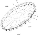
- each pocket 1 is arcuately shaped and together with a number of identical pockets, form a drum 50.
- the pockets 1 are fixed to a disk-shaped backing plate 2.
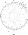
- the path of vacuum is from the hammermill, through the pockets, and is then turned toward the back of the apparatus (that is, away from the viewer in Fig.1B ), passing through openings 3 in the backing plate 2.
- the vacuum draws the fluff down from the hammermill to be deposited on the foraminous surface 4 of the pockets 1, as the vacuum passes through this foraminous surface and exits the back of the machine as explained above.
- a vacuum casing (not shown) encases the major portion of the drum, except in an arc sector area, generally in the form of a "slice of pie" area, where the pocket is shielded from vacuum, and the article formed therein can be removed.
- the pockets are removably attached to interfacing segments by primary attachment means, the distance between two adjacent primary attachment means being dependent on the pocket length (PL).
- These primary attachment means can be any suitable means.
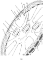
- One preferable means, shown herein in Fig.2 is to thread rods 5 into interfacing segments 6. Pockets 1 may then be formed with a matching semi-cylindrical groove 7 in each end. The spacing of rods 5 about interfacing segments 6 is such that each pocket 1 fits tightly between its respective rods. The length of each rod should be nearly but no greater than the width of the pockets.
- a bolt 8 is tightened into the outer end of each rod to hold each pocket tightly in position.
- the pockets could be simply bolted to interfacing segments 6 or affixed in any other secure but removable manner.
- the pockets 1 may advantageously be defined by longitudinal sidewalls 20 and transversal sidewalls 21, said transversal sidewalls having recesses 7, an air impervious top surface 22 and a foraminous surface 4 recessed below said air impervious top surface such that said top surface surrounds and defines two dimensions of the shape of the article to be formed, the distance by which the foraminous surface is below the top surface defining the third dimension, and said pockets 1 may be removably attached to said interfacing segments 6 by means of fastening rods 5 secured perpendicularly to said interfacing segments, which rods extend through said recesses 7 in the matching transversal sidewalls 21 of adjoining pockets 1. Then, preferably, the pockets 1 may be hold in position by bolts 8 screwed into the fastening rods 5.
- the interfacing segments 6 are removably attached to the backing plate 2 by secondary attachment means 9, the distance between two adjacent secondary attachment means being independent on the pocket length (PL).
- the interfacing segments 6 may be hold in position by bolts 9 screwed into the backing plate 2.
- an apparatus may show the advantage that only the pockets need to be swapped, whilst the interfacing segments remain affixed to the backing plate (see FIG.3 ).
- an apparatus according to the present invention may show the advantage that only the interfacing segments together with their pockets need to be changed (see FIG.2 ), and not the entire drum.
- the drum has to be manipulated or changed, thereby avoiding complex and dangerous operation, avoiding the risk of losing concentricity, avoiding the need for space to store various drums, avoiding to pay the cost of manufacturing various drums, avoiding the handling of all the pieces around the drum, and avoiding the adaptations needed when using drums with varying circumference.
- the drum 50 comprises at least two interfacing segments 6, of which at least one comprises more than one discrete pocket 1. Having less interfacing segments and ensuring that at least one interfacing segment bears more than one pocket may decrease the changeover time when an article size change has to be done. More preferably, the drum comprises at least 3, or at least 4, or at least 5 interfacing segments. The number of interfacing segments may be dependent on the length of the interfacing segments and the size (i.e. circumference) of the drum. Preferably, an interfacing segment comprises at least 2, or at least 3, or at least 4 discrete pockets. The number of pockets on an interfacing segment may be dependent on the length of the interfacing segments and the length of the pockets.
- drums e.g. drums having a diameter of at least 1,5 m, which comprise more pockets, e.g. more than 15 pockets. This is because it is easier to keep more or less the same diameter of the drum, whatever the length of the pockets is. The difference of only a few millimeters may then be easily compensated by product transport settings downstream the drum.
- a drum with a diameter of about 2 m, used for the manufacture of the absorbent core of sanitary napkins may comprise 21 pockets of the size NIGHT, 22 of the size SUPER, 26 of the size NORMAL, 29 of the size SHORT and 34 of the size MINI.
- the arc length of the interfacing segments is smaller than the arc length of the area of the drum which is not encased in the vacuum casing.
- a vacuum casing encases the major portion of the drum, except in an arc sector area, generally in the form of a "slice of pie" area, where the pocket is shielded from vacuum, and the article formed therein can be removed. If the length of the interfacings segments is smaller than this opening, said segments may easily be removed and replaced, without the need for switching the vacuum off, opening the vacuum casing, then reclosing the vacuum casing and waiting the vacuum to be appropriate again to restart production.
- the drum can easily be rotated, to allow access to each intermediate segment of the circumference.
- FIG.2 shows a drum with a diameter of about 2 m, used for the manufacture of the absorbent core of sanitary napkins of the size NORMAL, comprising 26 pockets and 6 interfacing segments.
- Four interfacing segments each carry 4 pockets, and two other interfacing segments each carry 2 pockets; finally, 6 pockets are sitting across the junctions between the individual interfacing segments.
- the drum is then turned until the next junction between two interfacing segments. There the pocket covering said junction is slid out and the next interfacing segment is removed and replaced. A new pocket can then be slid in and fixed, between the two newly replaced interfacing segment.
- the drum is then again turned until the next junction between two interfacing segments and the same operations are performed, until a last new pocket is slid in and fixed, between the last newly replaced interfacing segment and the first replaced interfacing segment.
- the replacement of an entire drum can generally take from 6 hours up to 2 days, depending on the configuration, the changeover according to the present invention can take between 10 and 30 minutes, which is highly advantageous.
- storing a few interfacing segments and pockets instead of an entire drum is much more convenient.
- a discrete pocket straddles two contiguous interfacing segments, so that the rods for fixing the pockets to the interfacing segments are fully included into the material of the interfacing segments. This may ensure good fixation and tight fit.
- the apparatus according to the present invention further comprises primary tongue and groove positioning means between the pockets and the interfacing segments.
- This may help ensuring a tight fit between the pockets and the interfacing segments.
- the prior art use of rods only to center and fix the pockets to the backing plate of a drum (as in US 4,674,966 for example) may lead to problems of loss of concentricity, i.e. roundness, of the drum, thereby leading to problems of stability of product manufacturing.
- the use of primary tongue and groove positioning means according to the present invention may solve this problem. It may also reduce the passageway of air from the exterior of the vacuum casing to said vacuum casing.
- the apparatus according to the present invention further comprises secondary tongue and groove positioning means between the interfacing segments and the backing plane. This may help ensuring a tight fit between the interfacing segments and the backing plate, ensuring drum's concentricity and/or reducing the passageway of air.
- the apparatus according to the present invention comprises both primary and secondary tongue and groove positioning means.
- Exemplary figure 4 which illustrates a cross-section at a junction between two pockets, shows a pocket made of two pieces: a cover 1a and a base 1b.
- the base of the pocket has a transversal sidewall (that is, facing the viewer of FIG.4 ) having a recess in the form of a semi-cylindrical groove, through which a fastening rod 5 extends.
- the fastening rod 5 is secured perpendicularly to the interfacing segment 6, and the pockets is hold in position by bolt 8 screwed into the fastening rod 5.
- the base of the pocket further comprises a tongue 10, adapted to fit into a corresponding groove 11 within the interfacing segment 6. Also visible on this figure, are the secondary tongue and groove positioning means 12 between the interfacing segment 6 and the backing plane 2.
- Exemplary figure 5 illustrates a cross-section within a pocket 1a-1b, across a secondary attachment means 9 used to removably attach the interfacing segment 6 to the backing plate 2. Also visible on this figure, are the primary tongue and groove positioning means 10-11 between the pocket base 1b and the interfacing segment 6 and the secondary tongue and groove positioning means 12 between the interfacing segment 6 and the backing plane 2.
- a compartment refers to one or more than one compartment.
- the value to which the modifier "about” refers is itself also specifically disclosed.
- Absorbent article refers to devices that absorb and contain liquid, and more specifically, refers to devices that are placed against or in proximity to the body of the wearer to absorb and contain the various exudates discharged from the body.
- Absorbent articles include but are not limited to diapers, adult incontinence briefs, training pants, diaper holders and liners, sanitary napkins and the like, as well as surgical bandages and sponges.
- Absorbent articles preferably comprise a longitudinal axis and a transversal axis perpendicular to said longitudinal axis.
- Disposable absorbent articles can include a liquid pervious top sheet, a back sheet joined to the top sheet, and an absorbent core positioned and held between the top sheet and the back sheet.
- the top sheet is operatively permeable to the liquids that are intended to be held or stored by the absorbent article, and the back sheet may or may not be substantially impervious or otherwise operatively impermeable to the intended liquids.
- the absorbent article may also include other components, such as liquid wicking layers, liquid intake layers, liquid distribution layers, transfer layers, barrier layers, wrapping layers and the like, as well as combinations thereof. Disposable absorbent articles and the components thereof can operate to provide a body-facing surface and a garment-facing surface.
- the "absorbent medium” or “absorbent core” or “absorbent body” is the absorbent structure disposed between the top sheet and the back sheet of the absorbent article in at least the crotch region of the absorbent article and is capable of absorbing and retaining liquid body exudates. It may be manufactured in a wide variety of shapes (for example, rectangular, trapezoidal, T-shape, I-shape, hourglass shape, etc.) and from a wide variety of materials. Examples of commonly occurring absorbent materials are cellulosic fluff pulp, tissue layers, highly absorbent polymers (so called superabsorbent polymer particles (SAP)), absorbent foam materials, absorbent nonwoven materials or the like. It is common to combine cellulosic fluff pulp with superabsorbent polymers in an absorbent material.
- the absorbent core can include one or more liquid absorbent layers.
- compositions consisting essentially of
- materials that do not significantly affect the desired characteristics of a given composition or product.
- Exemplary materials of this sort would include, without limitation, pigments, antioxidants, stabilizers, surfactants, waxes, flow promoters, solvents, particulates and materials added to enhance processability of the composition.
- Longitudinal is a direction running parallel to the maximum linear dimension of the article.
- Pulp fluff or "fluff pulp” refers to a material made up of cellulose fibers.
- the fibers can be either natural or synthetic, or a combination thereof.
- the material is typically lightweight and has absorbent properties.
- sanitary napkin refers to an article which is worn by females adjacent to the pudendal region that is intended to absorb and contain the various exudates which are discharged from the body (e. g., blood, menses, and urine).
- transverse refers to a line, axis, or direction which lies within the plane of the absorbent article and is generally perpendicular to the longitudinal direction.
- wrapping material preferably a sheet material of which the thickness is smaller, more preferably much smaller than its width or length, such as a sheet, a film or a foil.
- said wrapping material is capable of being rolled up.
- An absorbent core in particular an absorbent core comprising superabsorbent particles, preferably comprises a "wrap" or “wrap sheet” or “wrapping layer” so as to prevent the absorbent material and superabsorbent particles from escaping from the finished product.
Landscapes
- Health & Medical Sciences (AREA)
- Engineering & Computer Science (AREA)
- Vascular Medicine (AREA)
- Epidemiology (AREA)
- Biomedical Technology (AREA)
- Heart & Thoracic Surgery (AREA)
- Life Sciences & Earth Sciences (AREA)
- Animal Behavior & Ethology (AREA)
- General Health & Medical Sciences (AREA)
- Public Health (AREA)
- Veterinary Medicine (AREA)
- Manufacturing & Machinery (AREA)
- Absorbent Articles And Supports Therefor (AREA)
Claims (11)
- Vorrichtung zur Herstellung von luftgelegten Faserartikeln, umfassend eine Vielzahl von diskreten Taschen (1), die die Form der Artikel definiert, die in einer Umfangsbeziehung um die Peripherie einer drehbaren Abscheidungstrommel (50) angeordnet sind, umfassend eine scheibenförmige Trägerplatte (2), dadurch gekennzeichnet, dass die diskreten Taschen (1) entfernbar an Schnittstellensegmente (6) befestigt sind, die ihrerseits entfernbar an die Trägerplatte (2) befestigt sind.
- Vorrichtung nach Anspruch 1, wobei die Trommel (50) mindestens zwei Schnittstellensegmente (6) umfasst, von denen mindestens eines mehr als eine diskrete Tasche (1) umfasst.
- Vorrichtung nach Anspruch 1 oder Anspruch 2, wobei die diskreten Taschen (1) entfernbar an die Schnittstellensegmente durch primäre Befestigungsmittel (5) befestigt sind, wobei der Abstand zwischen zwei benachbarten primären Befestigungsmitteln von der Taschenlänge (PL) abhängt.
- Vorrichtung nach einem der vorhergehenden Ansprüche, wobei die Taschen (1) durch längs gerichtete Seitenwände (20) und quer gerichtete Seitenwände (21) definiert sind, wobei die quer gerichteten Seitenwände Aussparungen (7), eine luftundurchlässige obere Fläche (22) und eine durchstoßene Fläche (4) aufweisen, die unter der luftundurchlässigen oberen Fläche ausgespart ist, so dass die obere Fläche zwei Dimensionen der Form des Artikels, der geformt werden soll, umgibt und definiert, wobei der Abstand, um den sich die durchbrochene Fläche unter der oberen Fläche befindet, die dritte Dimension definiert, wobei die Taschen (1) entfernbar an die Schnittstellensegmente (6) mit Hilfe von Befestigungsstangen (5) befestigt sind, die senkrecht an die Schnittstellensegmente (6) gesichert sind, wobei sich die Stangen durch die Aussparungen (7) in den passenden quer liegenden Seitenwänden (21) von benachbarten Taschen (1) erstrecken.
- Vorrichtung nach Anspruch 4, wobei die Taschen (1) durch Bolzen in ihrer Position (8) gehalten werden, die in die Befestigungsstangen (5) geschraubt sind.
- Vorrichtung nach Anspruch 4 oder Anspruch 5, wobei eine diskrete Tasche zwei benachbarte Schnittstellensegmente überspannt.
- Vorrichtung nach einem der vorhergehenden Ansprüche, wobei die Schnittstellensegmente (6) entfernbar an die Trägerplatte (2) durch sekundäre Befestigungsmittel (9) befestigt sind, wobei der Abstand zwischen zwei benachbarten sekundären Befestigungsmitteln unabhängig von der Taschenlänge (PL) ist.
- Vorrichtung nach einem der vorhergehenden Ansprüche, weiter umfassend primäre Zungen- und Nuten-Positionierungsmittel (10, 11) zwischen den Taschen (1) und den Schnittstellensegmenten (6).
- Vorrichtung nach einem der vorhergehenden Ansprüche, weiter umfassend sekundäre Zungen- und Nuten-Positionierungsmittel (12) zwischen den Schnittstellensegmenten (6) und der Trägerplatte (2).
- Vorrichtung nach einem der vorhergehenden Ansprüche, umfassend ein Vakuumgehäuse, das den größten Teil der Trommel umgibt, außer in einem Bogensektorbereich, wobei die Bogenlänge der Schnittstellensegmente (ISL) kleiner als die Bogenlänge des Bogensektorbereichs der Trommel ist, die nicht vom Vakuumgehäuse umgeben ist.
- Verfahren zur Herstellung von saugfähigen Hygieneprodukten, umfassend.- Bereitstellen einer Vorrichtung nach einem der Ansprüche 1 bis 10,- Bilden von luftgelegten Faserartikeln mit der Vorrichtung,- Einschließen der luftgelegten Faserartikel als saugfähiger Kern in die saugfähigen Hygieneprodukte.
Priority Applications (3)
| Application Number | Priority Date | Filing Date | Title |
|---|---|---|---|
| EP18173368.4A EP3569207B1 (de) | 2018-05-18 | 2018-05-18 | Vorrichtung zur herstellung von luftgelegten faserartikeln |
| PCT/EP2018/083786 WO2019219228A1 (en) | 2018-05-18 | 2018-12-06 | Apparatus for making air-laid fibrous articles |
| US17/055,684 US12036100B2 (en) | 2018-05-18 | 2018-12-06 | Apparatus for making air-laid fibrous articles |
Applications Claiming Priority (1)
| Application Number | Priority Date | Filing Date | Title |
|---|---|---|---|
| EP18173368.4A EP3569207B1 (de) | 2018-05-18 | 2018-05-18 | Vorrichtung zur herstellung von luftgelegten faserartikeln |
Publications (2)
| Publication Number | Publication Date |
|---|---|
| EP3569207A1 EP3569207A1 (de) | 2019-11-20 |
| EP3569207B1 true EP3569207B1 (de) | 2021-07-14 |
Family
ID=62217890
Family Applications (1)
| Application Number | Title | Priority Date | Filing Date |
|---|---|---|---|
| EP18173368.4A Active EP3569207B1 (de) | 2018-05-18 | 2018-05-18 | Vorrichtung zur herstellung von luftgelegten faserartikeln |
Country Status (3)
| Country | Link |
|---|---|
| US (1) | US12036100B2 (de) |
| EP (1) | EP3569207B1 (de) |
| WO (1) | WO2019219228A1 (de) |
Families Citing this family (2)
| Publication number | Priority date | Publication date | Assignee | Title |
|---|---|---|---|---|
| JP7446525B2 (ja) * | 2022-03-28 | 2024-03-08 | ニチダイフィルタ株式会社 | 吸収体製造装置 |
| EP4368160A1 (de) * | 2022-11-09 | 2024-05-15 | Ontex BV | Formtasche zur formung einer ablagerungsstruktur aus geformtem saugfähigem material zur verwendung als saugfähiger kern für saugfähige artikel |
Family Cites Families (4)
| Publication number | Priority date | Publication date | Assignee | Title |
|---|---|---|---|---|
| US4674966A (en) | 1984-04-02 | 1987-06-23 | Winkler & Dunnebier | Apparatus for forming fibrous pads |
| ATE82597T1 (de) * | 1985-12-10 | 1992-12-15 | Kimberly Clark Co | Vorrichtung und verfahren fuer die erzeugung eines faservlieses. |
| DE19823954C2 (de) | 1998-05-28 | 2002-08-29 | Sca Hygiene Prod Ab | Verfahren und Vorrichtung zum Ausbilden luftaufgebrachter absorbierender Faserkerne |
| JP5765909B2 (ja) * | 2010-09-30 | 2015-08-19 | ユニ・チャーム株式会社 | 積繊装置の回転ドラム |
-
2018
- 2018-05-18 EP EP18173368.4A patent/EP3569207B1/de active Active
- 2018-12-06 WO PCT/EP2018/083786 patent/WO2019219228A1/en not_active Ceased
- 2018-12-06 US US17/055,684 patent/US12036100B2/en active Active
Also Published As
| Publication number | Publication date |
|---|---|
| US12036100B2 (en) | 2024-07-16 |
| WO2019219228A1 (en) | 2019-11-21 |
| EP3569207A1 (de) | 2019-11-20 |
| US20210186768A1 (en) | 2021-06-24 |
Similar Documents
| Publication | Publication Date | Title |
|---|---|---|
| US8198506B2 (en) | Stabilized absorbent composite | |
| US7718021B2 (en) | Method for making a stabilized absorbent composite | |
| US8221672B2 (en) | Method and apparatus for forming a batt of particulate material for use as a component in an absorbent core assembly | |
| US20120270715A1 (en) | Method of manufacturing absorbent member and apparatus used to manufacture the same | |
| US20210052434A1 (en) | Apparatus and method for forming absorbent cores | |
| CA2851169C (en) | Disposable absorbent product with multiple fluid storage structures and related methods | |
| US12036100B2 (en) | Apparatus for making air-laid fibrous articles | |
| WO2014004940A1 (en) | Methods and apparatuses for consolidating elastic substrates | |
| US20160030258A1 (en) | Pulpless absorbent core and method of core forming | |
| JP2024544312A (ja) | チャネルを含む失禁用品 | |
| WO2004030591A1 (en) | Disposable garments with improved elastic filament placement control and methods of producing same | |
| US6848894B2 (en) | Absorbent article, method and apparatus for preparing same | |
| KR101837920B1 (ko) | 브릿지형 흡수 용품 | |
| KR102506164B1 (ko) | 브릿지형 흡수성 구조체 제조 방법 | |
| JP6591136B2 (ja) | 吸収体及び吸収性物品の製造方法並びに吸収体及び吸収性物品の製造装置 | |
| JP2010509519A (ja) | エアレイド構造を製造するための装置 | |
| AU2019472942B2 (en) | Absorbent article | |
| RU2774288C2 (ru) | Способ изготовления листовых элементов, устройство для изготовления листовых элементов и способ получения впитывающей массы | |
| JP6822246B2 (ja) | 吸収体、該吸収体を備える吸収性物品、前記吸収体の製造方法および製造装置 | |
| SE508616C2 (sv) | Absorberande struktur |
Legal Events
| Date | Code | Title | Description |
|---|---|---|---|
| PUAI | Public reference made under article 153(3) epc to a published international application that has entered the european phase |
Free format text: ORIGINAL CODE: 0009012 |
|
| STAA | Information on the status of an ep patent application or granted ep patent |
Free format text: STATUS: THE APPLICATION HAS BEEN PUBLISHED |
|
| AK | Designated contracting states |
Kind code of ref document: A1 Designated state(s): AL AT BE BG CH CY CZ DE DK EE ES FI FR GB GR HR HU IE IS IT LI LT LU LV MC MK MT NL NO PL PT RO RS SE SI SK SM TR |
|
| AX | Request for extension of the european patent |
Extension state: BA ME |
|
| STAA | Information on the status of an ep patent application or granted ep patent |
Free format text: STATUS: REQUEST FOR EXAMINATION WAS MADE |
|
| 17P | Request for examination filed |
Effective date: 20200327 |
|
| RBV | Designated contracting states (corrected) |
Designated state(s): AL AT BE BG CH CY CZ DE DK EE ES FI FR GB GR HR HU IE IS IT LI LT LU LV MC MK MT NL NO PL PT RO RS SE SI SK SM TR |
|
| RAP1 | Party data changed (applicant data changed or rights of an application transferred) |
Owner name: ONTEX GROUP NV Owner name: ONTEX BVBA |
|
| RAP1 | Party data changed (applicant data changed or rights of an application transferred) |
Owner name: ONTEX GROUP NV Owner name: ONTEX BV |
|
| GRAP | Despatch of communication of intention to grant a patent |
Free format text: ORIGINAL CODE: EPIDOSNIGR1 |
|
| STAA | Information on the status of an ep patent application or granted ep patent |
Free format text: STATUS: GRANT OF PATENT IS INTENDED |
|
| INTG | Intention to grant announced |
Effective date: 20210428 |
|
| GRAS | Grant fee paid |
Free format text: ORIGINAL CODE: EPIDOSNIGR3 |
|
| GRAA | (expected) grant |
Free format text: ORIGINAL CODE: 0009210 |
|
| STAA | Information on the status of an ep patent application or granted ep patent |
Free format text: STATUS: THE PATENT HAS BEEN GRANTED |
|
| AK | Designated contracting states |
Kind code of ref document: B1 Designated state(s): AL AT BE BG CH CY CZ DE DK EE ES FI FR GB GR HR HU IE IS IT LI LT LU LV MC MK MT NL NO PL PT RO RS SE SI SK SM TR |
|
| REG | Reference to a national code |
Ref country code: GB Ref legal event code: FG4D |
|
| REG | Reference to a national code |
Ref country code: IE Ref legal event code: FG4D |
|
| REG | Reference to a national code |
Ref country code: DE Ref legal event code: R096 Ref document number: 602018019966 Country of ref document: DE |
|
| REG | Reference to a national code |
Ref country code: AT Ref legal event code: REF Ref document number: 1410078 Country of ref document: AT Kind code of ref document: T Effective date: 20210815 |
|
| REG | Reference to a national code |
Ref country code: LT Ref legal event code: MG9D |
|
| REG | Reference to a national code |
Ref country code: NL Ref legal event code: MP Effective date: 20210714 |
|
| REG | Reference to a national code |
Ref country code: AT Ref legal event code: MK05 Ref document number: 1410078 Country of ref document: AT Kind code of ref document: T Effective date: 20210714 |
|
| PG25 | Lapsed in a contracting state [announced via postgrant information from national office to epo] |
Ref country code: SE Free format text: LAPSE BECAUSE OF FAILURE TO SUBMIT A TRANSLATION OF THE DESCRIPTION OR TO PAY THE FEE WITHIN THE PRESCRIBED TIME-LIMIT Effective date: 20210714 Ref country code: RS Free format text: LAPSE BECAUSE OF FAILURE TO SUBMIT A TRANSLATION OF THE DESCRIPTION OR TO PAY THE FEE WITHIN THE PRESCRIBED TIME-LIMIT Effective date: 20210714 Ref country code: HR Free format text: LAPSE BECAUSE OF FAILURE TO SUBMIT A TRANSLATION OF THE DESCRIPTION OR TO PAY THE FEE WITHIN THE PRESCRIBED TIME-LIMIT Effective date: 20210714 Ref country code: ES Free format text: LAPSE BECAUSE OF FAILURE TO SUBMIT A TRANSLATION OF THE DESCRIPTION OR TO PAY THE FEE WITHIN THE PRESCRIBED TIME-LIMIT Effective date: 20210714 Ref country code: FI Free format text: LAPSE BECAUSE OF FAILURE TO SUBMIT A TRANSLATION OF THE DESCRIPTION OR TO PAY THE FEE WITHIN THE PRESCRIBED TIME-LIMIT Effective date: 20210714 Ref country code: LT Free format text: LAPSE BECAUSE OF FAILURE TO SUBMIT A TRANSLATION OF THE DESCRIPTION OR TO PAY THE FEE WITHIN THE PRESCRIBED TIME-LIMIT Effective date: 20210714 Ref country code: BG Free format text: LAPSE BECAUSE OF FAILURE TO SUBMIT A TRANSLATION OF THE DESCRIPTION OR TO PAY THE FEE WITHIN THE PRESCRIBED TIME-LIMIT Effective date: 20211014 Ref country code: AT Free format text: LAPSE BECAUSE OF FAILURE TO SUBMIT A TRANSLATION OF THE DESCRIPTION OR TO PAY THE FEE WITHIN THE PRESCRIBED TIME-LIMIT Effective date: 20210714 Ref country code: PT Free format text: LAPSE BECAUSE OF FAILURE TO SUBMIT A TRANSLATION OF THE DESCRIPTION OR TO PAY THE FEE WITHIN THE PRESCRIBED TIME-LIMIT Effective date: 20211115 Ref country code: NO Free format text: LAPSE BECAUSE OF FAILURE TO SUBMIT A TRANSLATION OF THE DESCRIPTION OR TO PAY THE FEE WITHIN THE PRESCRIBED TIME-LIMIT Effective date: 20211014 Ref country code: NL Free format text: LAPSE BECAUSE OF FAILURE TO SUBMIT A TRANSLATION OF THE DESCRIPTION OR TO PAY THE FEE WITHIN THE PRESCRIBED TIME-LIMIT Effective date: 20210714 |
|
| PG25 | Lapsed in a contracting state [announced via postgrant information from national office to epo] |
Ref country code: PL Free format text: LAPSE BECAUSE OF FAILURE TO SUBMIT A TRANSLATION OF THE DESCRIPTION OR TO PAY THE FEE WITHIN THE PRESCRIBED TIME-LIMIT Effective date: 20210714 Ref country code: LV Free format text: LAPSE BECAUSE OF FAILURE TO SUBMIT A TRANSLATION OF THE DESCRIPTION OR TO PAY THE FEE WITHIN THE PRESCRIBED TIME-LIMIT Effective date: 20210714 Ref country code: GR Free format text: LAPSE BECAUSE OF FAILURE TO SUBMIT A TRANSLATION OF THE DESCRIPTION OR TO PAY THE FEE WITHIN THE PRESCRIBED TIME-LIMIT Effective date: 20211015 |
|
| REG | Reference to a national code |
Ref country code: DE Ref legal event code: R097 Ref document number: 602018019966 Country of ref document: DE |
|
| PG25 | Lapsed in a contracting state [announced via postgrant information from national office to epo] |
Ref country code: DK Free format text: LAPSE BECAUSE OF FAILURE TO SUBMIT A TRANSLATION OF THE DESCRIPTION OR TO PAY THE FEE WITHIN THE PRESCRIBED TIME-LIMIT Effective date: 20210714 |
|
| PLBE | No opposition filed within time limit |
Free format text: ORIGINAL CODE: 0009261 |
|
| STAA | Information on the status of an ep patent application or granted ep patent |
Free format text: STATUS: NO OPPOSITION FILED WITHIN TIME LIMIT |
|
| PG25 | Lapsed in a contracting state [announced via postgrant information from national office to epo] |
Ref country code: SM Free format text: LAPSE BECAUSE OF FAILURE TO SUBMIT A TRANSLATION OF THE DESCRIPTION OR TO PAY THE FEE WITHIN THE PRESCRIBED TIME-LIMIT Effective date: 20210714 Ref country code: SK Free format text: LAPSE BECAUSE OF FAILURE TO SUBMIT A TRANSLATION OF THE DESCRIPTION OR TO PAY THE FEE WITHIN THE PRESCRIBED TIME-LIMIT Effective date: 20210714 Ref country code: RO Free format text: LAPSE BECAUSE OF FAILURE TO SUBMIT A TRANSLATION OF THE DESCRIPTION OR TO PAY THE FEE WITHIN THE PRESCRIBED TIME-LIMIT Effective date: 20210714 Ref country code: EE Free format text: LAPSE BECAUSE OF FAILURE TO SUBMIT A TRANSLATION OF THE DESCRIPTION OR TO PAY THE FEE WITHIN THE PRESCRIBED TIME-LIMIT Effective date: 20210714 Ref country code: CZ Free format text: LAPSE BECAUSE OF FAILURE TO SUBMIT A TRANSLATION OF THE DESCRIPTION OR TO PAY THE FEE WITHIN THE PRESCRIBED TIME-LIMIT Effective date: 20210714 Ref country code: AL Free format text: LAPSE BECAUSE OF FAILURE TO SUBMIT A TRANSLATION OF THE DESCRIPTION OR TO PAY THE FEE WITHIN THE PRESCRIBED TIME-LIMIT Effective date: 20210714 |
|
| 26N | No opposition filed |
Effective date: 20220419 |
|
| REG | Reference to a national code |
Ref country code: CH Ref legal event code: PL |
|
| PG25 | Lapsed in a contracting state [announced via postgrant information from national office to epo] |
Ref country code: MC Free format text: LAPSE BECAUSE OF FAILURE TO SUBMIT A TRANSLATION OF THE DESCRIPTION OR TO PAY THE FEE WITHIN THE PRESCRIBED TIME-LIMIT Effective date: 20210714 Ref country code: LU Free format text: LAPSE BECAUSE OF NON-PAYMENT OF DUE FEES Effective date: 20220518 Ref country code: LI Free format text: LAPSE BECAUSE OF NON-PAYMENT OF DUE FEES Effective date: 20220531 Ref country code: CH Free format text: LAPSE BECAUSE OF NON-PAYMENT OF DUE FEES Effective date: 20220531 |
|
| PG25 | Lapsed in a contracting state [announced via postgrant information from national office to epo] |
Ref country code: IE Free format text: LAPSE BECAUSE OF NON-PAYMENT OF DUE FEES Effective date: 20220518 |
|
| P01 | Opt-out of the competence of the unified patent court (upc) registered |
Effective date: 20230527 |
|
| PG25 | Lapsed in a contracting state [announced via postgrant information from national office to epo] |
Ref country code: HU Free format text: LAPSE BECAUSE OF FAILURE TO SUBMIT A TRANSLATION OF THE DESCRIPTION OR TO PAY THE FEE WITHIN THE PRESCRIBED TIME-LIMIT; INVALID AB INITIO Effective date: 20180518 |
|
| PG25 | Lapsed in a contracting state [announced via postgrant information from national office to epo] |
Ref country code: MK Free format text: LAPSE BECAUSE OF FAILURE TO SUBMIT A TRANSLATION OF THE DESCRIPTION OR TO PAY THE FEE WITHIN THE PRESCRIBED TIME-LIMIT Effective date: 20210714 Ref country code: CY Free format text: LAPSE BECAUSE OF FAILURE TO SUBMIT A TRANSLATION OF THE DESCRIPTION OR TO PAY THE FEE WITHIN THE PRESCRIBED TIME-LIMIT Effective date: 20210714 |
|
| PGFP | Annual fee paid to national office [announced via postgrant information from national office to epo] |
Ref country code: GB Payment date: 20240521 Year of fee payment: 7 |
|
| PG25 | Lapsed in a contracting state [announced via postgrant information from national office to epo] |
Ref country code: MT Free format text: LAPSE BECAUSE OF FAILURE TO SUBMIT A TRANSLATION OF THE DESCRIPTION OR TO PAY THE FEE WITHIN THE PRESCRIBED TIME-LIMIT Effective date: 20210714 |
|
| PGFP | Annual fee paid to national office [announced via postgrant information from national office to epo] |
Ref country code: IT Payment date: 20240524 Year of fee payment: 7 |
|
| PGFP | Annual fee paid to national office [announced via postgrant information from national office to epo] |
Ref country code: DE Payment date: 20250519 Year of fee payment: 8 |
|
| PGFP | Annual fee paid to national office [announced via postgrant information from national office to epo] |
Ref country code: BE Payment date: 20250520 Year of fee payment: 8 |
|
| PGFP | Annual fee paid to national office [announced via postgrant information from national office to epo] |
Ref country code: FR Payment date: 20250523 Year of fee payment: 8 |
|
| PG25 | Lapsed in a contracting state [announced via postgrant information from national office to epo] |
Ref country code: TR Free format text: LAPSE BECAUSE OF FAILURE TO SUBMIT A TRANSLATION OF THE DESCRIPTION OR TO PAY THE FEE WITHIN THE PRESCRIBED TIME-LIMIT Effective date: 20210714 |
|
| GBPC | Gb: european patent ceased through non-payment of renewal fee |
Effective date: 20250518 |
|
| PG25 | Lapsed in a contracting state [announced via postgrant information from national office to epo] |
Ref country code: GB Free format text: LAPSE BECAUSE OF NON-PAYMENT OF DUE FEES Effective date: 20250518 |
|
| PG25 | Lapsed in a contracting state [announced via postgrant information from national office to epo] |
Ref country code: IT Free format text: LAPSE BECAUSE OF NON-PAYMENT OF DUE FEES Effective date: 20250518 |