EP3569352B1 - Élément de serrage d'un système de serrage, en particulier d'un système de serrage point zéro, et système de serrage - Google Patents
Élément de serrage d'un système de serrage, en particulier d'un système de serrage point zéro, et système de serrage Download PDFInfo
- Publication number
- EP3569352B1 EP3569352B1 EP19163493.0A EP19163493A EP3569352B1 EP 3569352 B1 EP3569352 B1 EP 3569352B1 EP 19163493 A EP19163493 A EP 19163493A EP 3569352 B1 EP3569352 B1 EP 3569352B1
- Authority
- EP
- European Patent Office
- Prior art keywords
- clamping
- component
- clamping element
- radial direction
- annular
- Prior art date
- Legal status (The legal status is an assumption and is not a legal conclusion. Google has not performed a legal analysis and makes no representation as to the accuracy of the status listed.)
- Active
Links
Images

Classifications
-
- B—PERFORMING OPERATIONS; TRANSPORTING
- B23—MACHINE TOOLS; METAL-WORKING NOT OTHERWISE PROVIDED FOR
- B23Q—DETAILS, COMPONENTS, OR ACCESSORIES FOR MACHINE TOOLS, e.g. ARRANGEMENTS FOR COPYING OR CONTROLLING; MACHINE TOOLS IN GENERAL CHARACTERISED BY THE CONSTRUCTION OF PARTICULAR DETAILS OR COMPONENTS; COMBINATIONS OR ASSOCIATIONS OF METAL-WORKING MACHINES, NOT DIRECTED TO A PARTICULAR RESULT
- B23Q1/00—Members which are comprised in the general build-up of a form of machine, particularly relatively large fixed members
- B23Q1/0063—Connecting non-slidable parts of machine tools to each other
- B23Q1/0072—Connecting non-slidable parts of machine tools to each other using a clamping opening for receiving an insertion bolt or nipple
Definitions
- the invention relates to a clamping element of a clamping system, in particular a zero-point clamping system, the clamping element being designed for arrangement on a component to be clamped and for locking on or in a clamping receptacle of a clamping module.
- the tensioning element is designed as a tensioning bolt and has a retraction section running around a central axis, against which locking elements of the tensioning module act to retract and lock the tensioning element.
- the draw-in section can in particular have a conical shape.
- the clamping element has a bearing surface for resting on the component to be clamped.
- a clamping element in the form of a clamping bolt which provides an annular groove surrounding the bearing surface in the radial direction and an annular web surrounding the annular groove in the radial direction and designed to be elastically flexible in the radial direction. Due to the fact that the ring web is designed to be elastically resilient in the radial direction, the clamping bolt can be automatically centered in the clamping receptacle. Furthermore, undesired internal stresses in the clamped component, especially when using several clamping bolts on a component, can be suppressed.
- Zero-point clamping modules are clamping modules with which workpieces or workpiece carriers to be machined can be clamped with repeatable position accuracy. It is conceivable that several clamping modules are provided together on a carrier, for example on a clamping table or a clamping plate, in order to clamp larger workpieces by means of several clamping bolts provided on the workpiece or on the workpiece carrier.
- Clamping modules for receiving clamping elements in the form of clamping bolts or clamping rings are, for example, from DE 10 2010 010 898 A1 , the EP 1 707 307 A1 or the DE 10 2010 013 911 A1 known.
- the component to be clamped can be, for example, a workpiece to be machined or a workpiece carrier.
- the clamping elements are then locked for precisely positioned clamping in or on the respective clamping module.
- a clamping element is from the DE 10 2017 119 822 A1 , which belongs to the state of the art according to Art. 54(3) EPC a clamping receptacle of a clamping module, with a pull-in section running around a central axis, against which locking elements of the clamping module act to pull in and lock the clamping element, with a bearing surface for bearing on the component, with an annular groove surrounding the bearing surface in the radial direction and with a die Ring web surrounding the ring groove in the radial direction and designed to be elastically flexible at least in sections in the radial direction, the ring web having a plurality of openings extending in the radial direction.
- the invention is based on the object of further developing a clamping element of the type mentioned at the outset in such a way that, on the one hand, it is securely centered in the clamping receptacle during insertion and locking and, on the other hand, it is not damaged. Furthermore, the clamping element should be able to be locked without play.
- the clamping element according to the invention consequently provides that the annular web has a plurality of openings extending in the radial direction. These openings result in the ring web being designed to be elastically flexible in the radial direction. The elastic resilience can be adjusted depending on the number and size of the openings to be provided. The provision of openings also has the advantage that they can easily be introduced into the annular web.
- the EP 0 858 863 A1 in contrast, provides an annular web that is closed in the radial direction.
- Blind holes may be provided that run parallel to the central axis. An adjustment of the elastic resilience by means of the blind holes is not possible or only to a very limited extent possible.
- the present invention goes one step further and opens the annular ridge in the radial direction by providing the openings. An elastic resilience can thereby be set in a favorable manner in a simple manner.
- the clamping element is designed as a clamping bolt.
- the annular groove and the annular ridge are located radially on the outside with respect to the bearing surface.
- the openings are arranged at equidistant angular intervals around the central axis. It has been shown that a total of 10 to 20 openings and preferably 16 openings are advantageous.
- the openings can be in the form of round holes, oval holes and/or elongated holes.
- the openings are formed with open edges toward the component, so that the openings are formed in particular as oblong holes open on one side.
- the ring web is then formed by individual lamellae extending in the axial direction.
- the contact surface lies in a contact plane running perpendicular to the central axis and that the annular web or the lamellae has an underside facing the component to be clamped, which lies in a ring plane running perpendicular to the central axis, the ring plane being offset by a dimension x , with x > 0, is arranged at a distance from the support plane in the direction away from the component. Consequently, when the clamping element is installed, the support plane is in contact with the component and the ring plane is spaced apart from the component by the dimension x. As a result, an unhindered elastic deformation of the annular ridge or the lamellae forming the annular ridge can be ensured.
- the dimension x is advantageously so large that in the case of an elastically deformed annular ridge or elastically deformed lamellae, the underside of the annular ridge or the lamellae does not come into physical contact with the component.
- the openings between the lamellae can preferably be designed as oblong holes open at the edge, the oblong holes then having a base preferably running along a circular path on the side opposite the open side.
- the lamellae are square or substantially square in radial view. It has been shown that the square design of the lamellae with an edge length x leads to favorable elastic properties.
- the lamellae have a rectangular section and an adjoining, tapering conical section in longitudinal section on the side facing the component.
- the Rectangular section has a rectangular contour in cross section.
- the outer surface of the rectangular section runs parallel or substantially parallel to the opposite surface adjoining the annular groove.
- the tapering cone section then adjoins the rectangular section, the outer surface of which tapers as the distance from the component increases.
- the cone section has a bending edge running transversely to the central axis on the side facing away from the rectangular section.
- a type of defined flexure joint can be provided for the elastic deformation of the slats.
- the object mentioned at the outset is also achieved by a component to be clamped with at least one clamping element according to the invention.
- a clamping system with a component to be clamped, which provides at least one clamping element according to the invention.
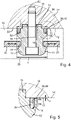
- the clamping element is designed in the form of a clamping bolt 10 .
- the clamping bolt 10 is used to arrange it on a component 12 to be clamped, which is in figure 4 is shown in sections and can be formed, for example, as a workpiece or workpiece carrier. How out figure 4 As becomes clear, the clamping bolt 10 is fastened with a fastening screw 14 which passes through the clamping bolt 10 and is screwed into a thread 16 provided on the component 12 .
- the clamping bolt 10 has a central bore 18 for this purpose.
- the screw 14 or the bore 18 runs along a central axis 20 of the clamping bolt 10.
- the clamping bolt 10 also has a raised, ring-like centering section 15, which is inserted into a ring receptacle provided on the component 12 for the precise positioning of the clamping bolt 10 on the component 12.
- the clamping bolt 10 has a draw-in section 22 running around the central axis 20 .
- Indicated clamping module 26 are provided in the clamping module 26 locking elements 24 which act against the feed section 22.
- the locking elements 24 can be shifted in the radial direction and can be designed as clamping slides or as locking balls. When the locking elements 24 are displaced radially inwards, they interact with the draw-in sections 22 in such a way that the clamping bolt 10 is drawn into the clamping receptacle 28 .
- the component 12 is loaded against a contact surface 30 provided on the clamping module 26 .
- the clamping bolt 10 has a ring-like bearing surface 32 for bearing on the component 12 .
- the bearing surface 32 lies in an in figure 3 and 5 indicated bearing plane 34.
- an annular groove 36 is provided, which surrounds the bearing surface 32 radially on the outside, and an annular web 38, which surrounds the annular groove 36 radially on the outside.
- the annular ridge 38 has a plurality of openings 40 extending through the annular ridge 38 in the radial direction. How from particular figure 2 becomes clear, a total of 16 openings 40 are provided. the Openings 40 are in the form of oblong holes and are open at the edge towards the component 12 . Overall, the ring web 38 thereby forms individual lamellae 42 extending in the axial direction and having a width a and a length a. A total of 16 lamellae 42 are provided, which are each arranged equidistantly around the central axis 20 .
- the lamellae 42 in the longitudinal section running through the central axis 20 have a rectangular section 44 on the side facing the component 12 and a conical section 46 adjoining the rectangular section 44 and tapering in the direction away from the component 12.
- the conical section 46 is also delimited on the side facing away from the rectangular section 44 by a bending edge 48 running transversely to the central axis 20 .
- the design of the lamellae 42 with a rectangular section 44, conical section 46 and bending edge 48 provides a lamella with a favorable geometry, with a type of solid-state joint in the area of the bending edge 48 for elastic flexibility of the lamellae 42 in the radial direction towards the central axis 20 on the lamellae 42 acting forces is provided.
- annular web 38 or the lamellae 42 have an underside 50 facing the component to be clamped, the underside 50 lying in an annular plane 52 running perpendicularly to the central axis 20 .
- the ring plane 52 is spaced apart from the support plane 34 by the dimension x.
- the dimension x is selected in such a way that the individual lamellae 42 can be elastically deformed in the axial direction in such a way that the undersides of the lamellae 50 do not come into physical contact with the component 12 .
- the outer diameter D of the clamping bolt 10 at the level of the rectangular sections 44 or in the ring plane 52 is slightly larger than the inner diameter d of the clamping receptacle 28. This allows the clamping bolt 10 be introduced into the clamping receptacle 28 without play and under prestress.
Landscapes
- Engineering & Computer Science (AREA)
- Mechanical Engineering (AREA)
- Clamps And Clips (AREA)
- Tone Control, Compression And Expansion, Limiting Amplitude (AREA)
- Picture Signal Circuits (AREA)
- Wire Bonding (AREA)
Claims (10)
- Elément de serrage (10) d'un système de serrage, en particulier d'un système de serrage au point zéro, dans lequel l'élément de serrage (10) est réalisé sous la forme d'un boulon de serrage (10), et dans lequel l'élément de serrage (10) est réalisé pour être disposé sur une pièce (12) à serrer et être verrouillé dans ou sur un logement de serrage (28) d'un module de serrage (26), avec une partie d'insertion (22) s'étendant autour d'un axe médian (20), contre laquelle agissent des éléments de verrouillage (24) du module de serrage (26) pour insérer et verrouiller l'élément de serrage (10), avec une surface d'appui (32) destinée à être en appui sur la pièce (12), avec une rainure annulaire (36) entourant la surface d'appui (32) dans la direction radiale et avec une nervure annulaire (38) entourant la rainure annulaire (36) dans la direction radiale, réalisée au moins en partie de manière élastiquement flexible dans la direction radiale, dans lequel la nervure annulaire (38) présente plusieurs passages (40) s'étendant dans la direction radiale, dans lequel la surface d'appui (32) se situe dans un plan d'appui (34) s'étendant perpendiculairement à l'axe médian, et dans lequel la nervure annulaire (38) présente une face inférieure tournée vers la pièce (12) à serrer, qui se situe dans un plan annulaire (52) s'étendant perpendiculairement à l'axe médian, dans lequel le plan annulaire (52) est disposé de manière espacée du plan d'appui (34) d'une grandeur x, avec x > 0, dans une direction s'éloignant de la pièce (12).
- Elément de serrage (10) selon la revendication 1, caractérisé en ce que les passages (40) sont disposés par intervalles angulaires équidistants autour de l'axe médian (20) .
- Elément de serrage (10) selon la revendication 1 ou 2, caractérisé en ce que les passages (40) sont réalisés sous la forme de trous ronds, sous la forme de trous ovales ou sous la forme de trous oblongs.
- Elément de serrage (10) selon la revendication 1, 2 ou 3, caractérisé en ce que les passages (40) sont réalisés de manière ouverte sur un bord en direction de la pièce, de sorte que la nervure annulaire (38) est formée par des lamelles (42) individuelles s'étendant dans la direction axiale.
- Elément de serrage (10) selon la revendication 4, caractérisé en ce que les lamelles (42) sont réalisées de manière carrée ou sensiblement carrée en vue radiale.
- Elément de serrage (10) selon la revendication 4 ou 5, caractérisé en ce que les lamelles (42) présentent en coupe longitudinale sur la face tournée vers la pièce une partie rectangulaire (44) et une partie conique (46) s'amincissant, se raccordant à celle-ci.
- Elément de serrage (10) selon la revendication 6, caractérisé en ce que la partie conique (46) présente sur la face opposée à la partie rectangulaire (44) un bord de pliage (48) s'étendant transversalement par rapport à l'axe médian.
- Elément de serrage (10) selon l'une quelconque des revendications précédentes, caractérisé en ce que la grandeur x est choisie de sorte que lorsque la nervure annulaire (38) est déformée élastiquement, la face inférieure (50) de la nervure annulaire (38) ne vient pas en contact avec la pièce (12) .
- Pièce (12) à serrer avec au moins un élément de serrage (10) selon au moins l'une des revendications précédentes.
- Système de serrage avec une pièce (12) à serrer avec au moins un et de préférence deux éléments de serrage (10) ou plus selon l'une quelconque des revendications 1 à 6, et avec au moins un et de préférence deux modules de serrage (26) ou plus pour la réception et le verrouillage de l'au moins un élément de serrage (10).
Applications Claiming Priority (1)
| Application Number | Priority Date | Filing Date | Title |
|---|---|---|---|
| DE102018111618.7A DE102018111618A1 (de) | 2018-05-15 | 2018-05-15 | Spannelement eines Spannsystems, insbesondere eines Nullpunktspannsystems, und Spannsystem |
Publications (2)
| Publication Number | Publication Date |
|---|---|
| EP3569352A1 EP3569352A1 (fr) | 2019-11-20 |
| EP3569352B1 true EP3569352B1 (fr) | 2023-01-18 |
Family
ID=65818355
Family Applications (1)
| Application Number | Title | Priority Date | Filing Date |
|---|---|---|---|
| EP19163493.0A Active EP3569352B1 (fr) | 2018-05-15 | 2019-03-18 | Élément de serrage d'un système de serrage, en particulier d'un système de serrage point zéro, et système de serrage |
Country Status (3)
| Country | Link |
|---|---|
| EP (1) | EP3569352B1 (fr) |
| DE (1) | DE102018111618A1 (fr) |
| ES (1) | ES2938984T3 (fr) |
Families Citing this family (5)
| Publication number | Priority date | Publication date | Assignee | Title |
|---|---|---|---|---|
| DE102019133760B4 (de) * | 2019-12-10 | 2023-05-04 | Innoclamp GmbH | Modulares Spannsystem und Verfahren |
| CN111571309A (zh) * | 2020-07-01 | 2020-08-25 | 上海工具厂有限公司 | 用于集成加工过程监控的零点定位夹具 |
| EP4082714A1 (fr) * | 2021-04-27 | 2022-11-02 | Officina Meccanica Lombarda S.r.l. | Goupille de verrouillage de pièces, notamment de moules, destinées à être usinées sur des machines-outils |
| DE102021118265A1 (de) * | 2021-07-14 | 2023-01-19 | Endress+Hauser Flowtec Ag | Feldgerät mit einem Sensor zur Erfassung einer physikalischen Messgröße und Klemmelement zur Befestigung eines Gehäuses eines Feldgeräts an einem Sensorhals |
| CN114799989B (zh) * | 2022-05-28 | 2023-03-31 | 苏州新火花机床有限公司 | 零点定位装置 |
Family Cites Families (8)
| Publication number | Priority date | Publication date | Assignee | Title |
|---|---|---|---|---|
| DE19705685C1 (de) * | 1997-02-14 | 1998-03-26 | Emil Stark | Spielfreier, vorgespannter Einzugsnippel für ein Schnellspannsystem |
| JP4762448B2 (ja) * | 2001-07-24 | 2011-08-31 | パスカルエンジニアリング株式会社 | ワークパレット位置決め固定装置 |
| DE502005007779D1 (de) * | 2005-03-31 | 2009-09-10 | Schunk Gmbh & Co Kg | Schnellspannsystem |
| WO2009096150A1 (fr) * | 2008-01-28 | 2009-08-06 | Pascal Engineering Corporation | Dispositif de positionnement et de fixation pour une palette de travail |
| DE102010010898C5 (de) * | 2010-03-05 | 2017-04-13 | Schunk Gmbh & Co. Kg | Nullpunktspannsystem |
| DE102010013911B4 (de) * | 2010-04-01 | 2013-07-25 | Schunk Gmbh & Co. Kg Spann- Und Greiftechnik | Spannmodul, insbesondere Nullpunktspannmodul |
| DE102010013912A1 (de) * | 2010-04-01 | 2011-10-06 | Schunk Gmbh & Co. Kg Spann- Und Greiftechnik | Spannbolzen zum Einspannen in ein Spannmodul und Spannsystem |
| DE102017119822B4 (de) * | 2017-08-29 | 2024-02-01 | Zeroclamp Gmbh | Doppelfunktion eines Zentrierkonus für eine Aufnahme einer Spannvorrichtung und Spannvorrichtung |
-
2018
- 2018-05-15 DE DE102018111618.7A patent/DE102018111618A1/de not_active Ceased
-
2019
- 2019-03-18 ES ES19163493T patent/ES2938984T3/es active Active
- 2019-03-18 EP EP19163493.0A patent/EP3569352B1/fr active Active
Also Published As
| Publication number | Publication date |
|---|---|
| EP3569352A1 (fr) | 2019-11-20 |
| ES2938984T3 (es) | 2023-04-18 |
| DE102018111618A1 (de) | 2019-11-21 |
Similar Documents
| Publication | Publication Date | Title |
|---|---|---|
| EP3569352B1 (fr) | Élément de serrage d'un système de serrage, en particulier d'un système de serrage point zéro, et système de serrage | |
| EP2371479B1 (fr) | Element de centrage, boulon de serrage, composant de support et système de serrage | |
| EP2357058B1 (fr) | Système de serrage, notamment système de serrage au point zéro | |
| EP3219435B1 (fr) | Élément de serrage de traction, en particulier boulon de serrage de traction ou bague de serrage de traction et système de serrage associé | |
| EP2759370B1 (fr) | Système de serrage, notamment système de serrage au point zéro, et boulon de serrage de compensation | |
| DE102014107701A1 (de) | Teleskopierbare Federstütze | |
| EP3308065B1 (fr) | Collier de serrage | |
| EP1704957B1 (fr) | Dispositif d'accouplement avec des parties élastiques pour une orientation en X et Y. | |
| DE102017119822A1 (de) | Zentrierkonus und Spannvorrichtung | |
| DE102019131050A1 (de) | Fließläppvorrichtung zum Glätten einer Fläche eines Werkstückes | |
| DE102013110671B4 (de) | Verschleißkörper zur Aufnahme einer Doppelschnecke zur Extrusion von schmelzfähigem Material | |
| EP3395496B1 (fr) | Unité de serrage pourvue de module de serrage et système de serrage | |
| DE102014103651A1 (de) | Clip aus Kunststoff zur Befestigung eines Gegenstands an einem Bolzen | |
| DE102013219954A1 (de) | Spannsystem, insbesondere Nullpunktspannsystem | |
| EP2766137A1 (fr) | Système d'outil pour l'usinage par enlèvement de copeaux d'une pièce | |
| EP3586017B1 (fr) | Dispositif de fixation et module de fixation | |
| EP1551092B1 (fr) | Couvercle de protection, en particulier pour générateur alternatif | |
| EP3186527B1 (fr) | Dispositif de ressort à cintrer | |
| EP3366417B1 (fr) | Boulon de tension d'un système de serrage | |
| EP0858863A1 (fr) | Broche précontrainte pour système de connection rapide sans jeu | |
| EP1515172B1 (fr) | Monture optique à faible contrainte | |
| DE102013226412B4 (de) | Spannmodul, insbesondere Nullpunktspannmodul und zugehöriges Spannsystem | |
| EP3241934A1 (fr) | Module d'outil textile et machine textile comprenant un module d'outil textile | |
| EP0849478B1 (fr) | Bande d'emballage pour éléments de fixation | |
| EP4330559B1 (fr) | Support de moyen de fixation, système de montage et procédé de montage d'un moyen de fixation |
Legal Events
| Date | Code | Title | Description |
|---|---|---|---|
| PUAI | Public reference made under article 153(3) epc to a published international application that has entered the european phase |
Free format text: ORIGINAL CODE: 0009012 |
|
| STAA | Information on the status of an ep patent application or granted ep patent |
Free format text: STATUS: THE APPLICATION HAS BEEN PUBLISHED |
|
| AK | Designated contracting states |
Kind code of ref document: A1 Designated state(s): AL AT BE BG CH CY CZ DE DK EE ES FI FR GB GR HR HU IE IS IT LI LT LU LV MC MK MT NL NO PL PT RO RS SE SI SK SM TR |
|
| AX | Request for extension of the european patent |
Extension state: BA ME |
|
| STAA | Information on the status of an ep patent application or granted ep patent |
Free format text: STATUS: REQUEST FOR EXAMINATION WAS MADE |
|
| 17P | Request for examination filed |
Effective date: 20200518 |
|
| RBV | Designated contracting states (corrected) |
Designated state(s): AL AT BE BG CH CY CZ DE DK EE ES FI FR GB GR HR HU IE IS IT LI LT LU LV MC MK MT NL NO PL PT RO RS SE SI SK SM TR |
|
| GRAP | Despatch of communication of intention to grant a patent |
Free format text: ORIGINAL CODE: EPIDOSNIGR1 |
|
| STAA | Information on the status of an ep patent application or granted ep patent |
Free format text: STATUS: GRANT OF PATENT IS INTENDED |
|
| INTG | Intention to grant announced |
Effective date: 20220803 |
|
| GRAS | Grant fee paid |
Free format text: ORIGINAL CODE: EPIDOSNIGR3 |
|
| GRAA | (expected) grant |
Free format text: ORIGINAL CODE: 0009210 |
|
| STAA | Information on the status of an ep patent application or granted ep patent |
Free format text: STATUS: THE PATENT HAS BEEN GRANTED |
|
| AK | Designated contracting states |
Kind code of ref document: B1 Designated state(s): AL AT BE BG CH CY CZ DE DK EE ES FI FR GB GR HR HU IE IS IT LI LT LU LV MC MK MT NL NO PL PT RO RS SE SI SK SM TR |
|
| REG | Reference to a national code |
Ref country code: GB Ref legal event code: FG4D Free format text: NOT ENGLISH |
|
| REG | Reference to a national code |
Ref country code: DE Ref legal event code: R096 Ref document number: 502019006803 Country of ref document: DE |
|
| REG | Reference to a national code |
Ref country code: CH Ref legal event code: EP |
|
| REG | Reference to a national code |
Ref country code: AT Ref legal event code: REF Ref document number: 1544410 Country of ref document: AT Kind code of ref document: T Effective date: 20230215 Ref country code: IE Ref legal event code: FG4D Free format text: LANGUAGE OF EP DOCUMENT: GERMAN |
|
| REG | Reference to a national code |
Ref country code: ES Ref legal event code: FG2A Ref document number: 2938984 Country of ref document: ES Kind code of ref document: T3 Effective date: 20230418 |
|
| REG | Reference to a national code |
Ref country code: LT Ref legal event code: MG9D |
|
| REG | Reference to a national code |
Ref country code: NL Ref legal event code: MP Effective date: 20230118 |
|
| PG25 | Lapsed in a contracting state [announced via postgrant information from national office to epo] |
Ref country code: NL Free format text: LAPSE BECAUSE OF FAILURE TO SUBMIT A TRANSLATION OF THE DESCRIPTION OR TO PAY THE FEE WITHIN THE PRESCRIBED TIME-LIMIT Effective date: 20230118 |
|
| PG25 | Lapsed in a contracting state [announced via postgrant information from national office to epo] |
Ref country code: RS Free format text: LAPSE BECAUSE OF FAILURE TO SUBMIT A TRANSLATION OF THE DESCRIPTION OR TO PAY THE FEE WITHIN THE PRESCRIBED TIME-LIMIT Effective date: 20230118 Ref country code: PT Free format text: LAPSE BECAUSE OF FAILURE TO SUBMIT A TRANSLATION OF THE DESCRIPTION OR TO PAY THE FEE WITHIN THE PRESCRIBED TIME-LIMIT Effective date: 20230518 Ref country code: NO Free format text: LAPSE BECAUSE OF FAILURE TO SUBMIT A TRANSLATION OF THE DESCRIPTION OR TO PAY THE FEE WITHIN THE PRESCRIBED TIME-LIMIT Effective date: 20230418 Ref country code: LV Free format text: LAPSE BECAUSE OF FAILURE TO SUBMIT A TRANSLATION OF THE DESCRIPTION OR TO PAY THE FEE WITHIN THE PRESCRIBED TIME-LIMIT Effective date: 20230118 Ref country code: LT Free format text: LAPSE BECAUSE OF FAILURE TO SUBMIT A TRANSLATION OF THE DESCRIPTION OR TO PAY THE FEE WITHIN THE PRESCRIBED TIME-LIMIT Effective date: 20230118 Ref country code: HR Free format text: LAPSE BECAUSE OF FAILURE TO SUBMIT A TRANSLATION OF THE DESCRIPTION OR TO PAY THE FEE WITHIN THE PRESCRIBED TIME-LIMIT Effective date: 20230118 |
|
| P01 | Opt-out of the competence of the unified patent court (upc) registered |
Effective date: 20230628 |
|
| PG25 | Lapsed in a contracting state [announced via postgrant information from national office to epo] |
Ref country code: SE Free format text: LAPSE BECAUSE OF FAILURE TO SUBMIT A TRANSLATION OF THE DESCRIPTION OR TO PAY THE FEE WITHIN THE PRESCRIBED TIME-LIMIT Effective date: 20230118 Ref country code: PL Free format text: LAPSE BECAUSE OF FAILURE TO SUBMIT A TRANSLATION OF THE DESCRIPTION OR TO PAY THE FEE WITHIN THE PRESCRIBED TIME-LIMIT Effective date: 20230118 Ref country code: IS Free format text: LAPSE BECAUSE OF FAILURE TO SUBMIT A TRANSLATION OF THE DESCRIPTION OR TO PAY THE FEE WITHIN THE PRESCRIBED TIME-LIMIT Effective date: 20230518 Ref country code: GR Free format text: LAPSE BECAUSE OF FAILURE TO SUBMIT A TRANSLATION OF THE DESCRIPTION OR TO PAY THE FEE WITHIN THE PRESCRIBED TIME-LIMIT Effective date: 20230419 Ref country code: FI Free format text: LAPSE BECAUSE OF FAILURE TO SUBMIT A TRANSLATION OF THE DESCRIPTION OR TO PAY THE FEE WITHIN THE PRESCRIBED TIME-LIMIT Effective date: 20230118 |
|
| REG | Reference to a national code |
Ref country code: DE Ref legal event code: R097 Ref document number: 502019006803 Country of ref document: DE |
|
| PG25 | Lapsed in a contracting state [announced via postgrant information from national office to epo] |
Ref country code: SM Free format text: LAPSE BECAUSE OF FAILURE TO SUBMIT A TRANSLATION OF THE DESCRIPTION OR TO PAY THE FEE WITHIN THE PRESCRIBED TIME-LIMIT Effective date: 20230118 Ref country code: RO Free format text: LAPSE BECAUSE OF FAILURE TO SUBMIT A TRANSLATION OF THE DESCRIPTION OR TO PAY THE FEE WITHIN THE PRESCRIBED TIME-LIMIT Effective date: 20230118 Ref country code: MC Free format text: LAPSE BECAUSE OF FAILURE TO SUBMIT A TRANSLATION OF THE DESCRIPTION OR TO PAY THE FEE WITHIN THE PRESCRIBED TIME-LIMIT Effective date: 20230118 Ref country code: EE Free format text: LAPSE BECAUSE OF FAILURE TO SUBMIT A TRANSLATION OF THE DESCRIPTION OR TO PAY THE FEE WITHIN THE PRESCRIBED TIME-LIMIT Effective date: 20230118 Ref country code: DK Free format text: LAPSE BECAUSE OF FAILURE TO SUBMIT A TRANSLATION OF THE DESCRIPTION OR TO PAY THE FEE WITHIN THE PRESCRIBED TIME-LIMIT Effective date: 20230118 Ref country code: CZ Free format text: LAPSE BECAUSE OF FAILURE TO SUBMIT A TRANSLATION OF THE DESCRIPTION OR TO PAY THE FEE WITHIN THE PRESCRIBED TIME-LIMIT Effective date: 20230118 |
|
| PLBE | No opposition filed within time limit |
Free format text: ORIGINAL CODE: 0009261 |
|
| STAA | Information on the status of an ep patent application or granted ep patent |
Free format text: STATUS: NO OPPOSITION FILED WITHIN TIME LIMIT |
|
| PG25 | Lapsed in a contracting state [announced via postgrant information from national office to epo] |
Ref country code: SK Free format text: LAPSE BECAUSE OF FAILURE TO SUBMIT A TRANSLATION OF THE DESCRIPTION OR TO PAY THE FEE WITHIN THE PRESCRIBED TIME-LIMIT Effective date: 20230118 |
|
| REG | Reference to a national code |
Ref country code: BE Ref legal event code: MM Effective date: 20230331 |
|
| 26N | No opposition filed |
Effective date: 20231019 |
|
| GBPC | Gb: european patent ceased through non-payment of renewal fee |
Effective date: 20230418 |
|
| PG25 | Lapsed in a contracting state [announced via postgrant information from national office to epo] |
Ref country code: LU Free format text: LAPSE BECAUSE OF NON-PAYMENT OF DUE FEES Effective date: 20230318 |
|
| REG | Reference to a national code |
Ref country code: IE Ref legal event code: MM4A |
|
| PG25 | Lapsed in a contracting state [announced via postgrant information from national office to epo] |
Ref country code: GB Free format text: LAPSE BECAUSE OF NON-PAYMENT OF DUE FEES Effective date: 20230418 |
|
| PG25 | Lapsed in a contracting state [announced via postgrant information from national office to epo] |
Ref country code: SI Free format text: LAPSE BECAUSE OF FAILURE TO SUBMIT A TRANSLATION OF THE DESCRIPTION OR TO PAY THE FEE WITHIN THE PRESCRIBED TIME-LIMIT Effective date: 20230118 Ref country code: IE Free format text: LAPSE BECAUSE OF NON-PAYMENT OF DUE FEES Effective date: 20230318 Ref country code: GB Free format text: LAPSE BECAUSE OF NON-PAYMENT OF DUE FEES Effective date: 20230418 |
|
| PG25 | Lapsed in a contracting state [announced via postgrant information from national office to epo] |
Ref country code: BE Free format text: LAPSE BECAUSE OF NON-PAYMENT OF DUE FEES Effective date: 20230331 |
|
| PG25 | Lapsed in a contracting state [announced via postgrant information from national office to epo] |
Ref country code: BG Free format text: LAPSE BECAUSE OF FAILURE TO SUBMIT A TRANSLATION OF THE DESCRIPTION OR TO PAY THE FEE WITHIN THE PRESCRIBED TIME-LIMIT Effective date: 20230118 |
|
| PG25 | Lapsed in a contracting state [announced via postgrant information from national office to epo] |
Ref country code: BG Free format text: LAPSE BECAUSE OF FAILURE TO SUBMIT A TRANSLATION OF THE DESCRIPTION OR TO PAY THE FEE WITHIN THE PRESCRIBED TIME-LIMIT Effective date: 20230118 |
|
| REG | Reference to a national code |
Ref country code: AT Ref legal event code: MM01 Ref document number: 1544410 Country of ref document: AT Kind code of ref document: T Effective date: 20240318 |
|
| PGFP | Annual fee paid to national office [announced via postgrant information from national office to epo] |
Ref country code: ES Payment date: 20250429 Year of fee payment: 7 |
|
| PGFP | Annual fee paid to national office [announced via postgrant information from national office to epo] |
Ref country code: CH Payment date: 20250401 Year of fee payment: 7 |
|
| PG25 | Lapsed in a contracting state [announced via postgrant information from national office to epo] |
Ref country code: AT Free format text: LAPSE BECAUSE OF NON-PAYMENT OF DUE FEES Effective date: 20240318 |
|
| PG25 | Lapsed in a contracting state [announced via postgrant information from national office to epo] |
Ref country code: CY Free format text: LAPSE BECAUSE OF FAILURE TO SUBMIT A TRANSLATION OF THE DESCRIPTION OR TO PAY THE FEE WITHIN THE PRESCRIBED TIME-LIMIT; INVALID AB INITIO Effective date: 20190318 |
|
| PG25 | Lapsed in a contracting state [announced via postgrant information from national office to epo] |
Ref country code: HU Free format text: LAPSE BECAUSE OF FAILURE TO SUBMIT A TRANSLATION OF THE DESCRIPTION OR TO PAY THE FEE WITHIN THE PRESCRIBED TIME-LIMIT; INVALID AB INITIO Effective date: 20190318 |
|
| PG25 | Lapsed in a contracting state [announced via postgrant information from national office to epo] |
Ref country code: TR Free format text: LAPSE BECAUSE OF FAILURE TO SUBMIT A TRANSLATION OF THE DESCRIPTION OR TO PAY THE FEE WITHIN THE PRESCRIBED TIME-LIMIT Effective date: 20230118 |
|
| REG | Reference to a national code |
Ref country code: CH Ref legal event code: U11 Free format text: ST27 STATUS EVENT CODE: U-0-0-U10-U11 (AS PROVIDED BY THE NATIONAL OFFICE) Effective date: 20260401 |
|
| PGFP | Annual fee paid to national office [announced via postgrant information from national office to epo] |
Ref country code: DE Payment date: 20260319 Year of fee payment: 8 |
|
| PGFP | Annual fee paid to national office [announced via postgrant information from national office to epo] |
Ref country code: AT Payment date: 20260410 Year of fee payment: 5 |
|
| PGFP | Annual fee paid to national office [announced via postgrant information from national office to epo] |
Ref country code: IT Payment date: 20260324 Year of fee payment: 8 |
|
| PGFP | Annual fee paid to national office [announced via postgrant information from national office to epo] |
Ref country code: FR Payment date: 20260320 Year of fee payment: 8 |