EP3569456B1 - Agencement de frein de stationnement et véhicule comprenant un tel agencement de frein de stationnement - Google Patents
Agencement de frein de stationnement et véhicule comprenant un tel agencement de frein de stationnement Download PDFInfo
- Publication number
- EP3569456B1 EP3569456B1 EP18172505.2A EP18172505A EP3569456B1 EP 3569456 B1 EP3569456 B1 EP 3569456B1 EP 18172505 A EP18172505 A EP 18172505A EP 3569456 B1 EP3569456 B1 EP 3569456B1
- Authority
- EP
- European Patent Office
- Prior art keywords
- park
- lock
- pawl
- park pawl
- bearing surface
- Prior art date
- Legal status (The legal status is an assumption and is not a legal conclusion. Google has not performed a legal analysis and makes no representation as to the accuracy of the status listed.)
- Active
Links
Images



Classifications
-
- B—PERFORMING OPERATIONS; TRANSPORTING
- B60—VEHICLES IN GENERAL
- B60T—VEHICLE BRAKE CONTROL SYSTEMS OR PARTS THEREOF; BRAKE CONTROL SYSTEMS OR PARTS THEREOF, IN GENERAL; ARRANGEMENT OF BRAKING ELEMENTS ON VEHICLES IN GENERAL; PORTABLE DEVICES FOR PREVENTING UNWANTED MOVEMENT OF VEHICLES; VEHICLE MODIFICATIONS TO FACILITATE COOLING OF BRAKES
- B60T1/00—Arrangements of braking elements, i.e. of those parts where braking effect occurs specially for vehicles
- B60T1/005—Arrangements of braking elements, i.e. of those parts where braking effect occurs specially for vehicles by locking of wheel or transmission rotation
-
- F—MECHANICAL ENGINEERING; LIGHTING; HEATING; WEAPONS; BLASTING
- F16—ENGINEERING ELEMENTS AND UNITS; GENERAL MEASURES FOR PRODUCING AND MAINTAINING EFFECTIVE FUNCTIONING OF MACHINES OR INSTALLATIONS; THERMAL INSULATION IN GENERAL
- F16H—GEARING
- F16H63/00—Control outputs from the control unit to change-speed- or reversing-gearings for conveying rotary motion or to other devices than the final output mechanism
- F16H63/02—Final output mechanisms therefor; Actuating means for the final output mechanisms
- F16H63/30—Constructional features of the final output mechanisms
- F16H63/34—Locking or disabling mechanisms
- F16H63/3416—Parking lock mechanisms or brakes in the transmission
-
- F—MECHANICAL ENGINEERING; LIGHTING; HEATING; WEAPONS; BLASTING
- F16—ENGINEERING ELEMENTS AND UNITS; GENERAL MEASURES FOR PRODUCING AND MAINTAINING EFFECTIVE FUNCTIONING OF MACHINES OR INSTALLATIONS; THERMAL INSULATION IN GENERAL
- F16H—GEARING
- F16H63/00—Control outputs from the control unit to change-speed- or reversing-gearings for conveying rotary motion or to other devices than the final output mechanism
- F16H63/02—Final output mechanisms therefor; Actuating means for the final output mechanisms
- F16H63/30—Constructional features of the final output mechanisms
- F16H63/34—Locking or disabling mechanisms
- F16H63/3416—Parking lock mechanisms or brakes in the transmission
- F16H63/3425—Parking lock mechanisms or brakes in the transmission characterised by pawls or wheels
-
- F—MECHANICAL ENGINEERING; LIGHTING; HEATING; WEAPONS; BLASTING
- F16—ENGINEERING ELEMENTS AND UNITS; GENERAL MEASURES FOR PRODUCING AND MAINTAINING EFFECTIVE FUNCTIONING OF MACHINES OR INSTALLATIONS; THERMAL INSULATION IN GENERAL
- F16H—GEARING
- F16H63/00—Control outputs from the control unit to change-speed- or reversing-gearings for conveying rotary motion or to other devices than the final output mechanism
- F16H63/02—Final output mechanisms therefor; Actuating means for the final output mechanisms
- F16H63/30—Constructional features of the final output mechanisms
- F16H63/34—Locking or disabling mechanisms
- F16H63/3416—Parking lock mechanisms or brakes in the transmission
- F16H63/3425—Parking lock mechanisms or brakes in the transmission characterised by pawls or wheels
- F16H63/3433—Details of latch mechanisms, e.g. for keeping pawls out of engagement
-
- F—MECHANICAL ENGINEERING; LIGHTING; HEATING; WEAPONS; BLASTING
- F16—ENGINEERING ELEMENTS AND UNITS; GENERAL MEASURES FOR PRODUCING AND MAINTAINING EFFECTIVE FUNCTIONING OF MACHINES OR INSTALLATIONS; THERMAL INSULATION IN GENERAL
- F16H—GEARING
- F16H63/00—Control outputs from the control unit to change-speed- or reversing-gearings for conveying rotary motion or to other devices than the final output mechanism
- F16H63/02—Final output mechanisms therefor; Actuating means for the final output mechanisms
- F16H63/30—Constructional features of the final output mechanisms
- F16H63/34—Locking or disabling mechanisms
- F16H63/3416—Parking lock mechanisms or brakes in the transmission
- F16H63/3458—Parking lock mechanisms or brakes in the transmission with electric actuating means, e.g. shift by wire
- F16H63/3466—Parking lock mechanisms or brakes in the transmission with electric actuating means, e.g. shift by wire using electric motors
-
- F—MECHANICAL ENGINEERING; LIGHTING; HEATING; WEAPONS; BLASTING
- F16—ENGINEERING ELEMENTS AND UNITS; GENERAL MEASURES FOR PRODUCING AND MAINTAINING EFFECTIVE FUNCTIONING OF MACHINES OR INSTALLATIONS; THERMAL INSULATION IN GENERAL
- F16H—GEARING
- F16H63/00—Control outputs from the control unit to change-speed- or reversing-gearings for conveying rotary motion or to other devices than the final output mechanism
- F16H63/02—Final output mechanisms therefor; Actuating means for the final output mechanisms
- F16H63/30—Constructional features of the final output mechanisms
- F16H63/34—Locking or disabling mechanisms
- F16H63/3416—Parking lock mechanisms or brakes in the transmission
- F16H63/3458—Parking lock mechanisms or brakes in the transmission with electric actuating means, e.g. shift by wire
- F16H63/3475—Parking lock mechanisms or brakes in the transmission with electric actuating means, e.g. shift by wire using solenoids
Definitions
- the present invention relates to a park lock arrangement for a vehicle and a vehicle comprising such a park lock arrangement.
- the park lock arrangement comprises a slideable park pawl adapted to slide between a release position to a lock position.
- Vehicles having an automatic transmission, or electric vehicles that do not have a gearbox are provided with a park lock function adapted to lock the output shaft of the automatic transmission or the output shaft of the electric motor, which restricts the vehicle from moving in any direction.
- a parking pawl prevents the transmission from rotating, and therefore the vehicle from moving.
- the parking pawl locks the transmission's output shaft to the transmission casing or the output shaft of the electric motor by engaging a pawl (a pin) that engages with a parking gear (a notched wheel) arranged on the output shaft, stopping it (and thus the driven wheels) from rotating.
- the parking pawl will lock the shaft when it extends down between two teeth of the parking gear.
- the parking gear may also be mounted in other positions, as long as it will be able to prevent the wheels of the vehicle to rotate.
- the parking pawl is prevented from being engaged during driving or when the vehicle is moving. On a vehicle having an automatic transmission, this is done by blocking the gear selector until a safe engagement speed for the vehicle is reached. Software may also be used to control that this condition is avoided and that the pawl can only be engaged when the vehicle has come to a standstill.
- the actuating means for the parking pawl is normally provided with a spring that will push the parking pawl towards the parking gear. If the vehicle stands still and the parking pawl bears on the top surface of a tooth, the parking pawl will be pushed against the top surface of the tooth. Should the vehicle move slightly, the parking pawl will be pushed down between the teeth by the spring and will lock the output shaft. With this solution, it is not important that the parking pawl extends down between the teeth directly when it is engaged.
- a park lock arrangement will normally comprise a longitudinally extended parking pawl which pivots around a pivot pin.
- the locking tooth of the parking pawl is arranged at one end of the parking pawl, at the opposite side from the pivot axis.
- An actuator device will pivot the parking pawl towards the parking gear.
- the actuator device normally comprises a conical bushing that will pivot the parking pawl towards the parking wheel.
- US 2015 025750 A , US 2016 025214 A and US 2010 193319 A all disclose such park lock arrangements. Such park lock arrangements normally functions relatively well, but are relatively large and heavy. There is thus room for improvements.
- US3386532 discloses a parking brake for use in a drive line and US5893439 discloses a parking mechanism comprising a parking stopper.
- An object of the invention is therefore to provide an improved park lock arrangement for a vehicle.
- a further object of the invention is to provide a vehicle comprising such a park lock arrangement.
- a park lock arrangement for a vehicle comprising a park pawl, an actuating means, where the park pawl is arranged to be in either a release position or in a lock position
- the object of the invention is achieved in that the park pawl comprises a body having a lock end and an actuation end, where the park pawl is arranged to slide between the release position and the lock position.
- a compact and light-weight park lock arrangement where the park pawl of the park lock arrangement can slide from a release position to a lock position in a radial direction with respect to the park gear.
- the park pawl By allowing the park pawl to slide instead of pivoting around a pivot axis, the park pawl can be made smaller and lighter.
- the complete park lock arrangement can thus be made smaller and a more compact installation can be obtained.
- the park lock arrangement comprises a return spring, arranged to push the park pawl towards the release position.
- the park pawl is suspended in a bushing surrounding the park pawl.
- the bushing is preferably made in a metal, e.g. steel. Since the transmission housing is made from aluminium or an aluminium alloy and the park pawl is preferably made from another material, e.g. steel, it is of advantage to use a bushing with the same properties as the park pawl. This will reduce the risk of galvanic corrosion between the transmission housing and the park pawl.
- the bushing must also be able to withstand the forces acting on the bushing from the park pawl and the parking gear. This force may be substantial, e.g. when the vehicle is parked in a downhill or uphill slope.
- the actuating means of the park lock arrangement is asymmetric, and in one example the cross section is rectangular.
- the use of a rectangular actuating means will allow for a more compact solution, and will further increase the bearing surface between the park pawl and the actuating means.
- the bearing surface of the actuating means can be flat, and the bearing surface of the park pawl can also be flat.
- the body of the park pawl is longitudinal.
- the body of the park pawl may be dimensioned with equally sized sides, or at least be quadratically shaped or be shaped as a cuboid. Regardless of the shape of the body, the corners of the body may be cut off (i.e. need not to be sharp), or may be bevelled, to provide inclined surfaces between the main sides of the body.
- the short sides of the park pawl may be straight or slightly convex.
- the friction between the park pawl and the bushing is reduced by letting one surface be convex. Since the bushing is tube shaped, and the park pawl is e.g. forged, it is easier to modify the side surfaces of the park pawl.
- the convex shape will also allow the park pawl to tilt somewhat in the bushing, which will distribute the force on a larger surface.
- the short sides of the park pawl may be slightly concave. Since the bushing is tube shaped, and the park pawl is e.g. forged, it is easier to modify the side surfaces of the park pawl. A concave shape will allow oil to enter between the park pawl and the bushing which will improve the lubrication of the park pawl.
- the edges of the lock end of the park pawl are inclined.
- the inclination will allow the park pawl to easier enter between two teeth of the parking gear.
- the amount of inclination preferably corresponds to the mesh angle of the parking gear.
- the face or flank angle of the parking gear teeth are often relatively straight, and the inclination of the edges of the park pawl will thus be dependent on the number of teeth and the face angle of the teeth.
- the edges of the actuation end of the park pawl are inclined.
- the inclination will allow the actuating means to easier slide against the actuation end between the lock position and the release position.
- the actuating means is provided with an inclined surface between the bearing surface of the release section and the bearing surface of the lock section.
- the inclination of the edges of the actuation end preferably corresponds to the inclination of the inclination surface of the actuating means.
- the park lock arrangement comprises a support roller, adapted to support the actuating means.
- the support roller will bear against the upper bearing surface of the actuating means, and will provide a support when pushing the park pawl to the lock position.
- the support roller will also bear against the actuating means when the park pawl is in the release position, where the actuating means is pushed towards the support roller by the return spring of the park lock arrangement.
- the support roller must be able to withstand the radial force acting on the support roller from the park pawl and the parking gear when the vehicle is parked in a slope. Since the system is adapted to be self-opening, i.e. the park pawl will exit the parking gear when the actuating means is removed from the park pawl, there is a radial force acting on the support roller.
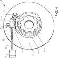
- Figures 1 to 4 show an inventive park lock arrangement
- Fig. 5 shows a vehicle comprising such a park lock arrangement.
- the park lock arrangement comprises a park pawl 2, an actuating means 7, and a return spring 12.
- the park pawl is arranged to be in either a release position, as is shown in Fig. 3 , in which the parking gear is free to rotate or in a lock position, as is shown in Fig. 4 , in which the parking gear is locked.
- the park pawl 2 is adapted to slide between the release position and the lock position.
- the park pawl is longitudinal with a rectangular cross-section.
- the park pawl comprises a body 3 having a lock end 4 and an actuation end 5.
- the short sides 21 of the body are adapted to interact with the bushing, transferring the force acting on the park pawl to the transmission housing.
- the long sides 22 of the park pawl body are adapted to be arranged in parallel with the parking gear.
- the long sides 22 of the park pawl body may also be slightly convex.
- the lock end 4 is adapted to interact with the teeth of the parking gear 20, and is provided with inclined bearing surfaces on the short sides 21 of the edges, a first lock bearing surface 27 and a second lock bearing surface 28.
- the first lock bearing surface 27 is adapted to block the parking gear from rotation in one direction
- the second lock bearing surface 28 is adapted to block the parking gear from rotation in the other direction.
- the inclination will allow the park pawl to easier enter between two teeth of the parking gear.
- the angle of a lock bearing surface is 30 degrees with respect to the centre axis 32 of the park pawl 2, but other inclination angles are also possible.
- a lock bearing surface must provide a secure locking of the parking gear.
- the inclination angle is preferably relatively acute, such that the park pawl will be able to hold the parking gear without deformation.
- the lock end 4 is also provided with a lock end bearing surface 23, which is adapted to bear against the top land of a tooth of the parking gear.
- the inclination of the lock bearing surfaces of the park pawl is also important in order to provide a park pawl that is self-opening, i.e. the park pawl will exit the parking gear when the holding support for the park pawl in the lock position is removed from the park pawl.
- the angle between the lock end 4 of the park pawl and the teeth of the parking gear must thus allow the park pawl to be pushed away from the parking gear.
- the actuation end 5 is adapted to interact with the actuating means 7.
- the actuation end 5 of the park pawl 2 is provided with inclined actuation bearing surfaces, a first actuation bearing surface 25 and a second actuation bearing surface 26. The inclination will allow the actuating means 7 to easier slide against the actuation end 5 between the release position and the lock position.
- the actuation end 5 is also provided with an actuation end bearing surface 24, which is adapted to bear against the actuating means 7.
- the actuating means 7 is provided with an inclined surface 11 between the bearing surface 31 of the release section 9 and the bearing surface 30 of the lock section 10.
- the bearing surface 30 of the lock section 10 is preferably substantially perpendicular to the centre axis 32 of the park pawl.
- the force acting on the park pawl when the vehicle is parked is transferred from the bearing surface 24 of the actuation end to the bearing surface 30 of the lock section 10 of the actuating means 7.
- These surfaces must thus correspond to each other and should be parallel to each other.
- the bearing surface 31 of the release section 9 must only take up the force from the return spring when the park pawl is in the release positon, and is not critical.
- the bearing surface 31 is also parallel to the bearing surface 24 of the actuation end of the park pawl 2.
- only the first actuation bearing surface 25 is used to slide against the inclined surface 11 of the actuating means 7, but it is of advantage to let the parking pawl be symmetric.
- the park pawl is preferably made from a metal, and may e.g. be made of forged steel or sintered steel. It is important that the park pawl can withstand the forces from the parking gear when the vehicle is parked in a slope.
- the parking gear is also made of steel.
- the park pawl 2 is suspended in a bushing 14 surrounding the park pawl.
- the bushing is mounted in a wall 19 of the transmission housing 18, which is made from aluminium or an aluminium alloy.
- the bushing is preferably made of steel or a metal alloy. It is of advantage to use a bushing with the same properties as the park pawl. The use of a bushing will reduce the risk of galvanic corrosion between the transmission housing and the park pawl, especially when they are made from different materials.
- the bushing must also be able to withstand the force acting on the bushing from the park pawl and the parking gear. This force may be substantial, e.g. when the vehicle is parked in a downhill or uphill slope.
- the inner walls of the bushing are preferably straight and parallel.
- the short sides 21 of the body 3 of the park pawl 2 are in the shown example straight. This will allow the park pawl to slide easily in the bushing 14. It is however possible to let the short sides be slightly convex or concave, depending on the design and mechanical properties of the park pawl. By letting the short sides 21 be slightly convex, the friction between the park pawl and the bushing may be reduced. The convex shape will allow the park pawl to tilt somewhat in the bushing, which will distribute the force on a larger surface.
- the friction between the park pawl and the bushing may also be reduced.
- a concave shape will allow oil to enter between the park pawl and the bushing which will improve the lubrication of the park pawl.
- a return spring 12 is arranged at the transmission housing 18. One end of the return spring bears on the transmission housing, and the other end is arranged in an opening 13 in the actuating end 5 of the park pawl.
- the return spring is arranged to push the park pawl towards the release position, such that the park pawl will be pushed away from the lock position regardless of the mounting position of the park pawl on the transmission housing.
- the park lock arrangement 1 is arranged at the top of the transmission housing, such that the park pawl is pushed upwards by the return spring.
- the return spring is a wound coil spring. Other types of springs are also possible to use, depending e.g. on the available space.
- the park lock arrangement comprises an actuating means 7 which is arranged to interact with the park pawl 2.
- the actuating means is adapted to move between a first position in which it allows the park pawl 2 to be in a release position, to a second position in which it forces the park pawl to the lock position.
- the actuating means 7 is arranged on an actuator rod 15 which runs through a longitudinal hole through the actuating means.
- the actuating means is able to slide on the actuator rod and is pushed to the end of the actuator rod 15 by an actuator spring 16.
- the actuator rod is controlled by an actuator 14, which may be e.g. an electromagnetic solenoid or a rotating motor.
- the actuator is controlled by the control system of the vehicle, and is activated when the transmission shift selector is placed in the park position, or when an electric vehicle is parked.
- the actuating means 7 of the park lock arrangement is asymmetric, and is in the shown example provided with a rectangular cross section, having parallel side walls 33.
- the use of a rectangular actuating means will allow for a more compact solution, and will further increase the bearing surface between the park pawl and the actuating means.
- the bearing surfaces 30, 31 of the actuating means can be flat, and the bearing surface 24 of the park pawl can also be flat.
- the thickness of the actuating means 7 may be the same as the thickness of the park pawl 2, i.e. correspond to the width of the short sides of the park pawl.
- the side walls may be supported in a sideway direction by support surfaces or rollers, or the actuator rod may be supported in a sideway manner, such that the actuating means moves along a straight line.
- the park lock arrangement 1 further comprises a support roller 17 arranged at the transmission housing 18.
- the support roller is adapted to support the park pawl 2 through the actuating means 7 and will take up the, in the shown example, vertical force acting on the park pawl when the park pawl is in the lock position.
- the support roller 17 will bear against the upper bearing surface 29 of the actuating means 7, and will provide a support when pushing the park pawl to the lock position.
- the support roller will also bear against the actuating means when the park pawl is in the release position, where the actuating means 7 is pushed towards the support roller 17 by the return spring 12 of the park lock arrangement. This is shown in Fig. 2 .
- the inclined surface 11 When the actuating means is moved from the release position to the lock position, the inclined surface 11 will come in contact with the first actuation bearing surface 25 of the actuation end 5 of the actuating means 7. If the park pawl is positioned such that it is directly between two teeth of the parking gear, the inclined surface 11 will push the park pawl down between the teeth and the actuating means 7 will move to the lock position, where the lock section bearing surface 30 of the lock section 10 bears against the actuation end bearing surface 24 of the actuation end 5 of the park pawl 2. This is shown in Fig. 4 .
- the actuator spring 16 will push the actuating means from the release position to the lock position when the actuator is controlled to lock the park lock arrangement 1. The spring force of the actuator spring 16 will overcome the force of the return spring 12 and the friction of the park pawl.
- the park pawl cannot be pushed down between the teeth of the parking gear.
- the park pawl will be pushed down somewhat, and the inclined surface 11 of the actuating means 7 will bear on the inclined first actuation bearing surface 25 of the actuation end 5 of the park pawl.
- the actuator spring will be compressed, and the actuator rod will partly slide through the opening in the actuating means. If the vehicle moves slightly, the parking gear will rotate some degrees such that the park pawl will be pushed down between the teeth of the parking gear by the actuating means.
- the inclined surface 11 will push the park pawl down and the lock section bearing surface 30 of the lock section 10 will bear on the park pawl.
- the actuating means 7 will at the same time move to the lock position by the actuator spring 16.
- Fig. 4 shows a vehicle 40 comprising an internal combustion engine 41 having an automatic transmission comprising a park lock arrangement 1 according to the invention.
- the vehicle may also comprise an electric motor comprising a park lock arrangement 1.
- the park lock arrangement is in the shown example arranged at the output shaft of the transmission or the electric motor, such that it can block the output shaft from rotation.
- the park lock arrangement may also be positioned in other positions of the drivetrain, as long as the park lock arrangement can prevent the output shaft to rotate.
Landscapes
- Engineering & Computer Science (AREA)
- General Engineering & Computer Science (AREA)
- Mechanical Engineering (AREA)
- Transportation (AREA)
- Gear-Shifting Mechanisms (AREA)
Claims (14)
- Agencement de verrouillage de stationnement (1) pour un véhicule, comprenant un cliquet de stationnement (2), un moyen d'actionnement (7), et un ressort de rappel (12), où le cliquet de stationnement (2) est agencé pour être dans une position de libération ou dans une position de verrouillage, dans lequel le cliquet de stationnement (2) est longitudinal et comprend un corps (3) ayant une extrémité de verrouillage (4) et une extrémité d'actionnement (5), où le cliquet de stationnement (2) est agencé pour coulisser entre la position de libération et la position de verrouillage, dans lequel une section de libération (9) du moyen d'actionnement (7) appuiera contre l'extrémité d'actionnement (5) du cliquet de stationnement (2) dans la position de libération, et une surface d'appui (30) d'une section de verrouillage (10) du moyen d'actionnement (7) appuiera contre une surface d'appui (24) de l'extrémité d'actionnement (5) du cliquet de stationnement (2) dans la position de verrouillage, dans lequel la surface d'appui (30) de la section de verrouillage (10) et la surface d'appui (24) de l'extrémité d'actionnement (5) sont parallèles dans la position de verrouillage.
- Agencement de verrouillage de stationnement selon la revendication 1, dans lequel l'agencement de verrouillage de stationnement (1) comprend une douille (6) agencée autour du cliquet de stationnement (2).
- Agencement de verrouillage de stationnement selon l'une quelconque des revendications précédentes, dans lequel la section transversale du corps (3) du cliquet de stationnement (2) est rectangulaire.
- Agencement de verrouillage de stationnement selon l'une quelconque des revendications précédentes, dans lequel les côtés courts (21) du corps (3) du cliquet de stationnement (2) sont droits.
- Agencement de verrouillage de stationnement selon l'une quelconque des revendications 1 à 3, dans lequel les côtés courts (21) du corps (3) du cliquet de stationnement (2) sont convexes.
- Agencement de verrouillage de stationnement selon l'une quelconque des revendications 1 à 3, dans lequel les côtés courts (21) du corps (3) du cliquet de stationnement (2) sont concaves.
- Agencement de verrouillage de stationnement selon l'une quelconque des revendications précédentes, dans lequel une première surface d'appui de verrouillage (27) et une seconde surface d'appui de verrouillage (28) de l'extrémité de verrouillage (4) du cliquet de stationnement (2) sont inclinées.
- Agencement de verrouillage de stationnement selon l'une quelconque des revendications précédentes, dans lequel au moins une surface d'appui d'actionnement (25, 26) de l'extrémité d'actionnement (5) du cliquet de stationnement (1) est inclinée.
- Agencement de verrouillage de stationnement selon l'une quelconque des revendications précédentes, dans lequel une surface d'appui supérieure (29) du moyen d'actionnement (7) est parallèle à la surface d'appui (30) de la section de verrouillage (10).
- Agencement de verrouillage de stationnement selon l'une quelconque des revendications précédentes, dans lequel les parois latérales (33) du corps (8) du moyen d'actionnement (7) sont parallèles.
- Agencement de verrouillage de stationnement selon l'une quelconque des revendications précédentes, dans lequel l'agencement de verrouillage de stationnement (1) comprend un rouleau de support (17) agencé pour appuyer contre la surface d'appui supérieure (29) du moyen d'actionnement (7).
- Agencement de verrouillage de stationnement selon l'une quelconque des revendications précédentes, dans lequel le moyen d'actionnement (7) comprend une surface inclinée (11) entre la surface d'appui (31) de la section de libération (9) et la surface d'appui (30) de la section de verrouillage (10).
- Agencement de verrouillage de stationnement selon l'une quelconque des revendications précédentes, dans lequel le moyen d'actionnement (7) est adapté pour réaliser un mouvement droit lorsqu'il pousse le cliquet de stationnement (2) depuis la position de libération jusqu'à la position de verrouillage.
- Véhicule, dans lequel le véhicule (40) comprend un agencement de verrouillage de stationnement (1) selon l'une quelconque des revendications 1 à 13.
Priority Applications (3)
| Application Number | Priority Date | Filing Date | Title |
|---|---|---|---|
| EP18172505.2A EP3569456B1 (fr) | 2018-05-15 | 2018-05-15 | Agencement de frein de stationnement et véhicule comprenant un tel agencement de frein de stationnement |
| CN201910378900.2A CN110486465A (zh) | 2018-05-15 | 2019-05-08 | 驻车锁定设备以及包括这种驻车锁定设备的车辆 |
| US16/409,928 US11131382B2 (en) | 2018-05-15 | 2019-05-13 | Park lock arrangement and vehicle comprising such a park lock arrangement |
Applications Claiming Priority (1)
| Application Number | Priority Date | Filing Date | Title |
|---|---|---|---|
| EP18172505.2A EP3569456B1 (fr) | 2018-05-15 | 2018-05-15 | Agencement de frein de stationnement et véhicule comprenant un tel agencement de frein de stationnement |
Publications (2)
| Publication Number | Publication Date |
|---|---|
| EP3569456A1 EP3569456A1 (fr) | 2019-11-20 |
| EP3569456B1 true EP3569456B1 (fr) | 2022-08-10 |
Family
ID=62196359
Family Applications (1)
| Application Number | Title | Priority Date | Filing Date |
|---|---|---|---|
| EP18172505.2A Active EP3569456B1 (fr) | 2018-05-15 | 2018-05-15 | Agencement de frein de stationnement et véhicule comprenant un tel agencement de frein de stationnement |
Country Status (3)
| Country | Link |
|---|---|
| US (1) | US11131382B2 (fr) |
| EP (1) | EP3569456B1 (fr) |
| CN (1) | CN110486465A (fr) |
Families Citing this family (1)
| Publication number | Priority date | Publication date | Assignee | Title |
|---|---|---|---|---|
| DE102020200770A1 (de) * | 2020-01-23 | 2021-07-29 | Zf Friedrichshafen Ag | Elektrischer Antrieb mit einer Parksperrenvorrichtung und Achsantriebsanordnung mit dem elektrischen Antrieb für ein Kraftfahrzeug |
Family Cites Families (22)
| Publication number | Priority date | Publication date | Assignee | Title |
|---|---|---|---|---|
| US3023631A (en) * | 1958-12-03 | 1962-03-06 | Warner Swasey Co | Single point thread attachment |
| US3386532A (en) * | 1966-01-05 | 1968-06-04 | Ford Motor Co | Parking brake for use in a driveline |
| JP2701405B2 (ja) * | 1988-12-29 | 1998-01-21 | いすゞ自動車株式会社 | 変速機の操作装置 |
| KR970075502A (ko) * | 1996-05-15 | 1997-12-10 | 박병재 | 자동 변속기용 파킹장치 |
| DE19643812A1 (de) | 1996-10-30 | 1998-05-07 | Zahnradfabrik Friedrichshafen | Parksperre für ein Automatgetriebe |
| US6367589B1 (en) * | 1999-11-01 | 2002-04-09 | New Holland North America, Inc. | Parking lock for agricultural implement |
| DE10052259B4 (de) * | 2000-10-19 | 2009-10-15 | Deere & Company, Moline | Notentriegelungseinrichtung für die Parksperre eines Kraftfahrzeugs |
| DE10105637A1 (de) * | 2001-02-08 | 2002-08-29 | Volkswagen Ag | Parksperrvorrichtung |
| KR100452598B1 (ko) * | 2001-12-24 | 2004-10-12 | 현대자동차주식회사 | 자동 변속기용 파킹기구 |
| JP4385651B2 (ja) * | 2003-05-28 | 2009-12-16 | いすゞ自動車株式会社 | 車両のパーキング装置 |
| KR20070045584A (ko) * | 2005-10-27 | 2007-05-02 | 현대자동차주식회사 | 자동변속기 차량의 주차장치 |
| GB2467378A (en) | 2009-02-02 | 2010-08-04 | Gm Global Tech Operations Inc | Transmission with a lock that prevents accidental park pawl reengagement |
| FR2956180A1 (fr) * | 2010-02-05 | 2011-08-12 | Renault Sas | Levier interne de frein de parking pour boite de vitesses et dispositif de frein de parking |
| GB201020092D0 (en) * | 2010-11-26 | 2011-01-12 | Camcon Oil Ltd | Shaft locking assembly |
| DE102010053505A1 (de) * | 2010-12-04 | 2012-06-06 | Volkswagen Ag | Vorrichtung zur Notbetätigung einer Parksperre |
| CN202812173U (zh) * | 2012-08-11 | 2013-03-20 | 株洲华盛实业有限公司 | 用于锁紧旋转传动机构的装置 |
| US8925706B2 (en) * | 2012-09-26 | 2015-01-06 | Dana Automotive Systems Group, Inc. | Vehicle parking brake control lever and pin with rollers |
| US9150214B2 (en) | 2013-07-18 | 2015-10-06 | Fca Us Llc | Techniques for robust park lock control |
| JP2016023764A (ja) | 2014-07-23 | 2016-02-08 | 株式会社デンソー | 制御装置、および、これを用いたシフトバイワイヤシステム |
| DE102016201177A1 (de) * | 2016-01-27 | 2017-07-27 | Schaeffler Technologies AG & Co. KG | Parksperrenvorrichtung für ein Fahrzeuggetriebe |
| DE102017212093A1 (de) * | 2017-07-14 | 2019-01-17 | Zf Friedrichshafen Ag | Parksperrenvorrichtung für ein Kraftfahrzeug |
| US10935131B2 (en) * | 2018-03-12 | 2021-03-02 | Dura Operating, Llc | Vehicle park lock assembly |
-
2018
- 2018-05-15 EP EP18172505.2A patent/EP3569456B1/fr active Active
-
2019
- 2019-05-08 CN CN201910378900.2A patent/CN110486465A/zh active Pending
- 2019-05-13 US US16/409,928 patent/US11131382B2/en active Active
Also Published As
| Publication number | Publication date |
|---|---|
| EP3569456A1 (fr) | 2019-11-20 |
| US11131382B2 (en) | 2021-09-28 |
| CN110486465A (zh) | 2019-11-22 |
| US20190353247A1 (en) | 2019-11-21 |
Similar Documents
| Publication | Publication Date | Title |
|---|---|---|
| US11085536B2 (en) | Actuating means for a park lock arrangement, park lock arrangement and vehicle comprising such a park lock arrangement | |
| CN101480940B (zh) | 基于转矩的停车锁组件 | |
| CN100482983C (zh) | 车辆用驻车锁止装置 | |
| EP3545207B1 (fr) | Frein de stationnement pour un véhicule automobile | |
| EP2041446B8 (fr) | Roue libre à complémentarité de forme à commande électromécanique, frein électromécanique de véhicule automobile pourvu d'une roue libre de ce type et procédé de réglage du jeu d'un frein de ce type | |
| CN109312857B (zh) | 用于机动车的驻车锁止器 | |
| US20140116835A1 (en) | Vehicle park lock assembly | |
| DE102017118622B4 (de) | Parkstellglied-baugruppe für ein automatgetriebe | |
| WO2010014313A1 (fr) | Unité d’ancrage à levier de frein réglable automatique avec un embrayage unidirectionnel | |
| CN115769008B (zh) | 用于车辆变速器的驻车锁装置以及车辆变速器 | |
| EP3569456B1 (fr) | Agencement de frein de stationnement et véhicule comprenant un tel agencement de frein de stationnement | |
| EP2420692A1 (fr) | Cartouche d'actionneur mécanique de frein de véhicule automobile | |
| US20200166131A1 (en) | Parking lock and a transmission having the parking lock | |
| EP3744586B1 (fr) | Dispositif de verrouillage de stationnement | |
| EP3747713B1 (fr) | Agencement de verrouillage de stationnement | |
| US8122786B2 (en) | Parking lock arrangement | |
| CN210290720U (zh) | 驻车驱动机构 | |
| CN113994126A (zh) | 驻车锁止器 | |
| US12180044B2 (en) | Rotation lock device, lever hoist, and hoisting machine | |
| WO2015063583A1 (fr) | Dispositif de verrouillage de stationnement | |
| WO2024251838A1 (fr) | Dispositif de blocage d'une transmission de chaîne cinématique dans un véhicule automobile | |
| DE102018107700A1 (de) | Vorrichtung zum Sperren und Freigeben eines funktionswesentlichen Bauteils eines Fahrzeuges | |
| RU2409782C2 (ru) | Система автоматического переключения передач ступенчатой трансмиссии транспортного средства и устройство блокировки механизма переключения передач этой системы | |
| HK40103733A (zh) | 一种电子机械制动装置用驻车制动执行机构 | |
| US5901609A (en) | Method and apparatus for a low friction safelock system |
Legal Events
| Date | Code | Title | Description |
|---|---|---|---|
| PUAI | Public reference made under article 153(3) epc to a published international application that has entered the european phase |
Free format text: ORIGINAL CODE: 0009012 |
|
| STAA | Information on the status of an ep patent application or granted ep patent |
Free format text: STATUS: THE APPLICATION HAS BEEN PUBLISHED |
|
| AK | Designated contracting states |
Kind code of ref document: A1 Designated state(s): AL AT BE BG CH CY CZ DE DK EE ES FI FR GB GR HR HU IE IS IT LI LT LU LV MC MK MT NL NO PL PT RO RS SE SI SK SM TR |
|
| AX | Request for extension of the european patent |
Extension state: BA ME |
|
| STAA | Information on the status of an ep patent application or granted ep patent |
Free format text: STATUS: REQUEST FOR EXAMINATION WAS MADE |
|
| 17P | Request for examination filed |
Effective date: 20200520 |
|
| RBV | Designated contracting states (corrected) |
Designated state(s): AL AT BE BG CH CY CZ DE DK EE ES FI FR GB GR HR HU IE IS IT LI LT LU LV MC MK MT NL NO PL PT RO RS SE SI SK SM TR |
|
| GRAP | Despatch of communication of intention to grant a patent |
Free format text: ORIGINAL CODE: EPIDOSNIGR1 |
|
| STAA | Information on the status of an ep patent application or granted ep patent |
Free format text: STATUS: GRANT OF PATENT IS INTENDED |
|
| INTG | Intention to grant announced |
Effective date: 20220419 |
|
| GRAS | Grant fee paid |
Free format text: ORIGINAL CODE: EPIDOSNIGR3 |
|
| GRAA | (expected) grant |
Free format text: ORIGINAL CODE: 0009210 |
|
| STAA | Information on the status of an ep patent application or granted ep patent |
Free format text: STATUS: THE PATENT HAS BEEN GRANTED |
|
| AK | Designated contracting states |
Kind code of ref document: B1 Designated state(s): AL AT BE BG CH CY CZ DE DK EE ES FI FR GB GR HR HU IE IS IT LI LT LU LV MC MK MT NL NO PL PT RO RS SE SI SK SM TR |
|
| REG | Reference to a national code |
Ref country code: AT Ref legal event code: REF Ref document number: 1510305 Country of ref document: AT Kind code of ref document: T Effective date: 20220815 Ref country code: CH Ref legal event code: EP |
|
| REG | Reference to a national code |
Ref country code: IE Ref legal event code: FG4D |
|
| REG | Reference to a national code |
Ref country code: DE Ref legal event code: R096 Ref document number: 602018038977 Country of ref document: DE |
|
| REG | Reference to a national code |
Ref country code: NL Ref legal event code: MP Effective date: 20220810 |
|
| REG | Reference to a national code |
Ref country code: LT Ref legal event code: MG9D |
|
| PG25 | Lapsed in a contracting state [announced via postgrant information from national office to epo] |
Ref country code: SE Free format text: LAPSE BECAUSE OF FAILURE TO SUBMIT A TRANSLATION OF THE DESCRIPTION OR TO PAY THE FEE WITHIN THE PRESCRIBED TIME-LIMIT Effective date: 20220810 Ref country code: RS Free format text: LAPSE BECAUSE OF FAILURE TO SUBMIT A TRANSLATION OF THE DESCRIPTION OR TO PAY THE FEE WITHIN THE PRESCRIBED TIME-LIMIT Effective date: 20220810 Ref country code: PT Free format text: LAPSE BECAUSE OF FAILURE TO SUBMIT A TRANSLATION OF THE DESCRIPTION OR TO PAY THE FEE WITHIN THE PRESCRIBED TIME-LIMIT Effective date: 20221212 Ref country code: NO Free format text: LAPSE BECAUSE OF FAILURE TO SUBMIT A TRANSLATION OF THE DESCRIPTION OR TO PAY THE FEE WITHIN THE PRESCRIBED TIME-LIMIT Effective date: 20221110 Ref country code: NL Free format text: LAPSE BECAUSE OF FAILURE TO SUBMIT A TRANSLATION OF THE DESCRIPTION OR TO PAY THE FEE WITHIN THE PRESCRIBED TIME-LIMIT Effective date: 20220810 Ref country code: LV Free format text: LAPSE BECAUSE OF FAILURE TO SUBMIT A TRANSLATION OF THE DESCRIPTION OR TO PAY THE FEE WITHIN THE PRESCRIBED TIME-LIMIT Effective date: 20220810 Ref country code: LT Free format text: LAPSE BECAUSE OF FAILURE TO SUBMIT A TRANSLATION OF THE DESCRIPTION OR TO PAY THE FEE WITHIN THE PRESCRIBED TIME-LIMIT Effective date: 20220810 Ref country code: FI Free format text: LAPSE BECAUSE OF FAILURE TO SUBMIT A TRANSLATION OF THE DESCRIPTION OR TO PAY THE FEE WITHIN THE PRESCRIBED TIME-LIMIT Effective date: 20220810 |
|
| REG | Reference to a national code |
Ref country code: AT Ref legal event code: MK05 Ref document number: 1510305 Country of ref document: AT Kind code of ref document: T Effective date: 20220810 |
|
| PG25 | Lapsed in a contracting state [announced via postgrant information from national office to epo] |
Ref country code: PL Free format text: LAPSE BECAUSE OF FAILURE TO SUBMIT A TRANSLATION OF THE DESCRIPTION OR TO PAY THE FEE WITHIN THE PRESCRIBED TIME-LIMIT Effective date: 20220810 Ref country code: IS Free format text: LAPSE BECAUSE OF FAILURE TO SUBMIT A TRANSLATION OF THE DESCRIPTION OR TO PAY THE FEE WITHIN THE PRESCRIBED TIME-LIMIT Effective date: 20221210 Ref country code: HR Free format text: LAPSE BECAUSE OF FAILURE TO SUBMIT A TRANSLATION OF THE DESCRIPTION OR TO PAY THE FEE WITHIN THE PRESCRIBED TIME-LIMIT Effective date: 20220810 Ref country code: GR Free format text: LAPSE BECAUSE OF FAILURE TO SUBMIT A TRANSLATION OF THE DESCRIPTION OR TO PAY THE FEE WITHIN THE PRESCRIBED TIME-LIMIT Effective date: 20221111 |
|
| PG25 | Lapsed in a contracting state [announced via postgrant information from national office to epo] |
Ref country code: SM Free format text: LAPSE BECAUSE OF FAILURE TO SUBMIT A TRANSLATION OF THE DESCRIPTION OR TO PAY THE FEE WITHIN THE PRESCRIBED TIME-LIMIT Effective date: 20220810 Ref country code: RO Free format text: LAPSE BECAUSE OF FAILURE TO SUBMIT A TRANSLATION OF THE DESCRIPTION OR TO PAY THE FEE WITHIN THE PRESCRIBED TIME-LIMIT Effective date: 20220810 Ref country code: ES Free format text: LAPSE BECAUSE OF FAILURE TO SUBMIT A TRANSLATION OF THE DESCRIPTION OR TO PAY THE FEE WITHIN THE PRESCRIBED TIME-LIMIT Effective date: 20220810 Ref country code: DK Free format text: LAPSE BECAUSE OF FAILURE TO SUBMIT A TRANSLATION OF THE DESCRIPTION OR TO PAY THE FEE WITHIN THE PRESCRIBED TIME-LIMIT Effective date: 20220810 Ref country code: CZ Free format text: LAPSE BECAUSE OF FAILURE TO SUBMIT A TRANSLATION OF THE DESCRIPTION OR TO PAY THE FEE WITHIN THE PRESCRIBED TIME-LIMIT Effective date: 20220810 Ref country code: AT Free format text: LAPSE BECAUSE OF FAILURE TO SUBMIT A TRANSLATION OF THE DESCRIPTION OR TO PAY THE FEE WITHIN THE PRESCRIBED TIME-LIMIT Effective date: 20220810 |
|
| REG | Reference to a national code |
Ref country code: DE Ref legal event code: R097 Ref document number: 602018038977 Country of ref document: DE |
|
| PG25 | Lapsed in a contracting state [announced via postgrant information from national office to epo] |
Ref country code: SK Free format text: LAPSE BECAUSE OF FAILURE TO SUBMIT A TRANSLATION OF THE DESCRIPTION OR TO PAY THE FEE WITHIN THE PRESCRIBED TIME-LIMIT Effective date: 20220810 Ref country code: EE Free format text: LAPSE BECAUSE OF FAILURE TO SUBMIT A TRANSLATION OF THE DESCRIPTION OR TO PAY THE FEE WITHIN THE PRESCRIBED TIME-LIMIT Effective date: 20220810 |
|
| PLBE | No opposition filed within time limit |
Free format text: ORIGINAL CODE: 0009261 |
|
| STAA | Information on the status of an ep patent application or granted ep patent |
Free format text: STATUS: NO OPPOSITION FILED WITHIN TIME LIMIT |
|
| PG25 | Lapsed in a contracting state [announced via postgrant information from national office to epo] |
Ref country code: AL Free format text: LAPSE BECAUSE OF FAILURE TO SUBMIT A TRANSLATION OF THE DESCRIPTION OR TO PAY THE FEE WITHIN THE PRESCRIBED TIME-LIMIT Effective date: 20220810 |
|
| 26N | No opposition filed |
Effective date: 20230511 |
|
| PG25 | Lapsed in a contracting state [announced via postgrant information from national office to epo] |
Ref country code: SI Free format text: LAPSE BECAUSE OF FAILURE TO SUBMIT A TRANSLATION OF THE DESCRIPTION OR TO PAY THE FEE WITHIN THE PRESCRIBED TIME-LIMIT Effective date: 20220810 |
|
| REG | Reference to a national code |
Ref country code: CH Ref legal event code: PL |
|
| P01 | Opt-out of the competence of the unified patent court (upc) registered |
Effective date: 20231212 |
|
| PG25 | Lapsed in a contracting state [announced via postgrant information from national office to epo] |
Ref country code: MC Free format text: LAPSE BECAUSE OF FAILURE TO SUBMIT A TRANSLATION OF THE DESCRIPTION OR TO PAY THE FEE WITHIN THE PRESCRIBED TIME-LIMIT Effective date: 20220810 |
|
| REG | Reference to a national code |
Ref country code: BE Ref legal event code: MM Effective date: 20230531 |
|
| PG25 | Lapsed in a contracting state [announced via postgrant information from national office to epo] |
Ref country code: MC Free format text: LAPSE BECAUSE OF FAILURE TO SUBMIT A TRANSLATION OF THE DESCRIPTION OR TO PAY THE FEE WITHIN THE PRESCRIBED TIME-LIMIT Effective date: 20220810 Ref country code: LU Free format text: LAPSE BECAUSE OF NON-PAYMENT OF DUE FEES Effective date: 20230515 Ref country code: LI Free format text: LAPSE BECAUSE OF NON-PAYMENT OF DUE FEES Effective date: 20230531 Ref country code: CH Free format text: LAPSE BECAUSE OF NON-PAYMENT OF DUE FEES Effective date: 20230531 |
|
| REG | Reference to a national code |
Ref country code: IE Ref legal event code: MM4A |
|
| PG25 | Lapsed in a contracting state [announced via postgrant information from national office to epo] |
Ref country code: IE Free format text: LAPSE BECAUSE OF NON-PAYMENT OF DUE FEES Effective date: 20230515 |
|
| PG25 | Lapsed in a contracting state [announced via postgrant information from national office to epo] |
Ref country code: IE Free format text: LAPSE BECAUSE OF NON-PAYMENT OF DUE FEES Effective date: 20230515 |
|
| PG25 | Lapsed in a contracting state [announced via postgrant information from national office to epo] |
Ref country code: IT Free format text: LAPSE BECAUSE OF FAILURE TO SUBMIT A TRANSLATION OF THE DESCRIPTION OR TO PAY THE FEE WITHIN THE PRESCRIBED TIME-LIMIT Effective date: 20220810 Ref country code: BE Free format text: LAPSE BECAUSE OF NON-PAYMENT OF DUE FEES Effective date: 20230531 |
|
| PG25 | Lapsed in a contracting state [announced via postgrant information from national office to epo] |
Ref country code: BG Free format text: LAPSE BECAUSE OF FAILURE TO SUBMIT A TRANSLATION OF THE DESCRIPTION OR TO PAY THE FEE WITHIN THE PRESCRIBED TIME-LIMIT Effective date: 20220810 |
|
| PG25 | Lapsed in a contracting state [announced via postgrant information from national office to epo] |
Ref country code: BG Free format text: LAPSE BECAUSE OF FAILURE TO SUBMIT A TRANSLATION OF THE DESCRIPTION OR TO PAY THE FEE WITHIN THE PRESCRIBED TIME-LIMIT Effective date: 20220810 |
|
| PGFP | Annual fee paid to national office [announced via postgrant information from national office to epo] |
Ref country code: DE Payment date: 20250423 Year of fee payment: 8 |
|
| PGFP | Annual fee paid to national office [announced via postgrant information from national office to epo] |
Ref country code: GB Payment date: 20250423 Year of fee payment: 8 |
|
| PGFP | Annual fee paid to national office [announced via postgrant information from national office to epo] |
Ref country code: FR Payment date: 20250423 Year of fee payment: 8 |
|
| PG25 | Lapsed in a contracting state [announced via postgrant information from national office to epo] |
Ref country code: CY Free format text: LAPSE BECAUSE OF FAILURE TO SUBMIT A TRANSLATION OF THE DESCRIPTION OR TO PAY THE FEE WITHIN THE PRESCRIBED TIME-LIMIT; INVALID AB INITIO Effective date: 20180515 |
|
| PG25 | Lapsed in a contracting state [announced via postgrant information from national office to epo] |
Ref country code: HU Free format text: LAPSE BECAUSE OF FAILURE TO SUBMIT A TRANSLATION OF THE DESCRIPTION OR TO PAY THE FEE WITHIN THE PRESCRIBED TIME-LIMIT; INVALID AB INITIO Effective date: 20180515 |
|
| PG25 | Lapsed in a contracting state [announced via postgrant information from national office to epo] |
Ref country code: TR Free format text: LAPSE BECAUSE OF FAILURE TO SUBMIT A TRANSLATION OF THE DESCRIPTION OR TO PAY THE FEE WITHIN THE PRESCRIBED TIME-LIMIT Effective date: 20220810 |