EP3569816B1 - Vorrichtung und verfahren zur verwendung eines multi-bit symbolstroms in richtbohrsystemen - Google Patents
Vorrichtung und verfahren zur verwendung eines multi-bit symbolstroms in richtbohrsystemen Download PDFInfo
- Publication number
- EP3569816B1 EP3569816B1 EP19179465.0A EP19179465A EP3569816B1 EP 3569816 B1 EP3569816 B1 EP 3569816B1 EP 19179465 A EP19179465 A EP 19179465A EP 3569816 B1 EP3569816 B1 EP 3569816B1
- Authority
- EP
- European Patent Office
- Prior art keywords
- frequency
- frequencies
- symbol
- transmitter
- depth
- Prior art date
- Legal status (The legal status is an assumption and is not a legal conclusion. Google has not performed a legal analysis and makes no representation as to the accuracy of the status listed.)
- Active
Links
Images


Classifications
-
- G—PHYSICS
- G01—MEASURING; TESTING
- G01S—RADIO DIRECTION-FINDING; RADIO NAVIGATION; DETERMINING DISTANCE OR VELOCITY BY USE OF RADIO WAVES; LOCATING OR PRESENCE-DETECTING BY USE OF THE REFLECTION OR RERADIATION OF RADIO WAVES; ANALOGOUS ARRANGEMENTS USING OTHER WAVES
- G01S11/00—Systems for determining distance or velocity not using reflection or reradiation
- G01S11/02—Systems for determining distance or velocity not using reflection or reradiation using radio waves
- G01S11/06—Systems for determining distance or velocity not using reflection or reradiation using radio waves using intensity measurements
-
- E—FIXED CONSTRUCTIONS
- E21—EARTH OR ROCK DRILLING; MINING
- E21B—EARTH OR ROCK DRILLING; OBTAINING OIL, GAS, WATER, SOLUBLE OR MELTABLE MATERIALS OR A SLURRY OF MINERALS FROM WELLS
- E21B7/00—Special methods or apparatus for drilling
- E21B7/04—Directional drilling
- E21B7/046—Directional drilling horizontal drilling
-
- E—FIXED CONSTRUCTIONS
- E21—EARTH OR ROCK DRILLING; MINING
- E21B—EARTH OR ROCK DRILLING; OBTAINING OIL, GAS, WATER, SOLUBLE OR MELTABLE MATERIALS OR A SLURRY OF MINERALS FROM WELLS
- E21B47/00—Survey of boreholes or wells
- E21B47/02—Determining slope or direction
- E21B47/024—Determining slope or direction of devices in the borehole
-
- E—FIXED CONSTRUCTIONS
- E21—EARTH OR ROCK DRILLING; MINING
- E21B—EARTH OR ROCK DRILLING; OBTAINING OIL, GAS, WATER, SOLUBLE OR MELTABLE MATERIALS OR A SLURRY OF MINERALS FROM WELLS
- E21B47/00—Survey of boreholes or wells
- E21B47/12—Means for transmitting measuring-signals or control signals from the well to the surface, or from the surface to the well, e.g. for logging while drilling
- E21B47/13—Means for transmitting measuring-signals or control signals from the well to the surface, or from the surface to the well, e.g. for logging while drilling by electromagnetic energy, e.g. radio frequency
-
- E—FIXED CONSTRUCTIONS
- E21—EARTH OR ROCK DRILLING; MINING
- E21B—EARTH OR ROCK DRILLING; OBTAINING OIL, GAS, WATER, SOLUBLE OR MELTABLE MATERIALS OR A SLURRY OF MINERALS FROM WELLS
- E21B7/00—Special methods or apparatus for drilling
- E21B7/04—Directional drilling
-
- E—FIXED CONSTRUCTIONS
- E21—EARTH OR ROCK DRILLING; MINING
- E21B—EARTH OR ROCK DRILLING; OBTAINING OIL, GAS, WATER, SOLUBLE OR MELTABLE MATERIALS OR A SLURRY OF MINERALS FROM WELLS
- E21B47/00—Survey of boreholes or wells
- E21B47/12—Means for transmitting measuring-signals or control signals from the well to the surface, or from the surface to the well, e.g. for logging while drilling
Definitions
- the present application is generally related to the field of communications relating to an inground device and, more particularly, to advanced inground device communication protocol using multi-bit data symbol and associated methods.
- a technique that is often referred to as horizontal directional drilling (HDD) can be used for purposes of installing a utility without the need to dig a trench.
- a typical utility installation involves the use of a drill rig having a drill string that supports a boring tool at a distal or inground end of the drill string.
- the drill rig forces the boring tool through the ground by applying a thrust force to the drill string.
- the boring tool is steered during the extension of the drill string to form a pilot bore.
- the distal end of the drill string is attached to a pullback apparatus which is, in turn, attached to a leading end of the utility.
- the pullback apparatus and utility are then pulled through the pilot bore via retraction of the drill string to complete the installation.
- the pullback apparatus can comprise a back reaming tool which serves to expand the diameter of the pilot bore ahead of the utility so that the installed utility can be of a greater diameter than the original diameter of the pilot bore.
- Steering of a boring tool can be accomplished in a well-known manner by orienting an asymmetric face of the boring tool for deflection in a desired direction in the ground responsive to forward movement.
- the sensor readings for example, can be modulated onto a locating signal that is transmitted by the electronics package for reception above ground by a portable locator or other suitable above ground device.
- the electronics package can couple a carrier signal modulated by the sensor readings onto the drill string to then transmit the signal to the drill rig by using the drill string as an electrical conductor.
- the transmission range can be still further limited by factors such as, for example, electromagnetic interference that is present in the operational region.
- electromagnetic interference that is present in the operational region.
- One prior art approach, in attempting to increase transmission range, is to transmit data from the boring tool or other inground tool at what Applicants refer to herein as a "magic frequency.”
- the latter can be characterized as a carrier frequency that remarkably avoids environmental interference to provide for effective reception range despite the wide variety of environmental interference that may be encountered.
- Applicants submit that such a magic frequency does not exist at least on the basis of application to any sort of broad geographic region and particularly on the basis of worldwide application.
- US 6,285,190 discloses arrangements, specific apparatus and associated methods for skin depth compensation in underground boring applications. Compensation for skin depth error is accomplished by measuring a locating signal transmitted from a boring tool such that measurements of the locating signal include skin depth error introduced as a result of the electrical conductivity characteristic of the earth. Thereafter, the measurements are used in a way which determines a skin depth corrected position of the boring tool.
- a multi-frequency approach is provided which utilizes measured intensities of the locating field at two or more frequencies to extrapolate a zero frequency value of intensity. The zero frequency value of intensity is then used in position determination.
- the multi-frequency approach does not require knowledge of earth properties or ground surface geometry since components of the measured magnetic field intensities of the locating field measured at nonzero frequencies contain property and geometry effects and pass them on to extrapolated zero frequency values. Skin depth compensation in a number of locating scenarios using a single frequency locating signal is introduced.
- US 2002/105331 discloses arrangements, apparatus and associated methods for use in a multi-frequency boring tool locating system.
- the boring tool includes a transmitter for transmitting a locating signal at two or more selectable frequencies.
- One set of above ground procedures may be applied to the transmitter in order to change the frequency of the boring tool transmitter.
- Another set of procedures is applicable for changing the frequency during below ground drilling operations, for example, by subjecting the boring tool to a predetermined roll orientation sequence.
- An enhanced portable locator operates in a manual or automatic mode to receive locating frequency information transmitted from the boring tool transmitter including frequency updates.
- Boring tool transmitter, as well as above ground locator shutdown/restart procedures are described relating to multi-frequency operation.
- a tone detector is described which implements one or more digital match filters.
- US 5,467,083 discloses a wireless downhole electromagnetic data transmission system and method that utilize microprocessor controlled frequency synthesis for two-way communication between the surface and a downhole guided boring or drilling apparatus in the range of from 100 Hz to 100 KHz.
- a non-magnetic downhole probe unit connected between a drill motor or drill bit and the drill string contains data gathering and transmission components including accelerometers which measure the earth's gravity vector and fluxgate magnetometers which read the earth's magnetic field and serve as power line proximity sensors.
- the drill pipe acts as an electrical lossy, single conductor with the earth forming the electrical return path.
- Sensory data gathered by the downhole probe is encoded in digital format and impressed upon the drill string using frequency shift keying of the electromagnetic energy waves and is picked off at the surface by a signal receiver-demodulator and message processor unit.
- the surface unit instructs the downhole probe to transmit multiple frequencies and selects one or more frequencies with the most favorable signal-to-noise ratio(s) in response to local conditions to maximize the transmission distance at a selective frequency band range and given transmitter power level and baud rate.
- the received signal is filtered, demodulated, processed and displayed at the surface and gravity and magnetic field vectors are combined with the created hole length to calculate x, y, and z hole coordinates and derive hole position vectors.
- US 6,776,246 discloses a portable area monitoring system for use with a horizontal directional drilling machine and adapted to produce a composite of the positions of a beacon and a fixed object.
- the sensor assembly is supported by a hand-held frame and adapted to detect signals emanating from each of a beacon and a fixed object.
- the sensor assembly transmits the detected signals to a processor which simultaneously processes the signals to produce a composite of relative positions of the beacon and the fixed object to the frame.
- the composite of the relative positions of the beacon and the fixed object to the frame is communicated to the operator using a portable display.
- this writing discloses a communication protocol in directional drilling system; apparatus and method utilizing multi-bit data symbol transmission.
- a bit for purposes of the present application, is a binary data value having two states characterized such as 1/0, +/-, and the like.
- a symbol for purposes of the present disclosure, is a data value that represents one or more bits.
- a multi-bit symbol represents two or more bits.
- a symbol can characterize any suitable type of information such as, for example, pitch data, roll data, temperature data, battery data and synchronization data, without limitation.
- Different multi-bit symbols represent different, multi-bit data values. For example, 16 different symbols can represent a four bit data value.
- Each multi-bit symbol for purposes of the present disclosure, is represented by a distinct frequency that is different from the frequency that is associated with any other multi-bit symbol.
- a symbol stream is made up of a serial transmission of multi-bit symbols such that the symbol stream is decodable into a corresponding digital data stream, which can be binary.
- the symbol stream can be transmitted subject to a packet structure such that the particular position of a given symbol within the packet structure defines a data type that is associated with that symbol.
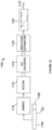
- Figure 1 illustrates one embodiment of a system for performing an inground operation, generally indicated by the reference number 10.
- the system includes a portable device 20 that is shown being held by an operator above a surface 22 of the ground as well as in a further enlarged inset view. It is noted that only limited inter-component cabling is shown within device 20 in order to maintain illustrative clarity, but all necessary cabling is understood to be present and may readily be implemented by one having ordinary skill in the art in view of this overall disclosure.
- Device 20 includes a three-axis antenna cluster 26 measuring three orthogonally arranged components of magnetic flux.
- Antenna cluster 26 is electrically connected to an electronics section 32.
- a tilt sensor arrangement 34 may be provided for measuring gravitational angles from which the components of flux in a level coordinate system may be determined.
- An appropriate tilt sensor includes, by way of non-limiting example, a triaxial accelerometer.
- Device 20 can further include a graphics display 36 and a telemetry antenna 40.
- graphics display 36 can be a touch screen in order to facilitate operator selection of various buttons that are defined on the screen and/or scrolling can be facilitated between various buttons that are defined on the screen to provide for operator selection.
- Such a touch screen can be used alone or in combination with an input device 48 such as, for example, a trigger button. The latter can be used without the need for a touch screen.
- many variations of the input device may be employed and can use scroll wheels and other suitable forms of selection device either currently available or yet to be developed.
- the electronics section can include components such as, for example, one or more processors, memory of any appropriate type, antenna drivers and analog to digital converters. As is well known in the art, the latter should be capable of detecting a frequency that is at least twice the frequency of the highest frequency of interest. Other components may be added as desired such as, for example, a magnetometer 50 to aid in position determination relative to the drill direction and ultrasonic transducers for measuring the height of the device above the surface of the ground.
- system 10 further includes drill rig 80 having a carriage 82 received for movement along the length of an opposing pair of rails 84.
- An inground tool 90 is attached at an opposing end of a drill string 92.
- a boring tool is shown as the inground tool and is used as a framework for the present descriptions, however, it is to be understood that any suitable inground device may be used such as, for example, a reaming tool for use during a pullback operation or a mapping tool.
- drill string 92 is made up of a plurality of removably attachable drill pipe sections such that the drill rig can force the drill string into the ground using movement in the direction of an arrow 94 and retract the drill string responsive to an opposite movement.
- the drill pipe sections can define a through passage for purposes of carrying a drilling mud or fluid that is emitted from the boring tool under pressure to assist in cutting through the ground as well as cooling the drill head.
- the drilling mud also serves to suspend and carry out cuttings to the surface along the exterior length of the drill string.
- Steering can be accomplished in a well-known manner by orienting an asymmetric face 96 of the boring tool for deflection in a desired direction in the ground responsive to forward, push movement which can be referred to as a "push mode.”
- Rotation or spinning 98 of the drill string by the drill rig will generally result in forward or straight advance of the boring tool which can be referred to as a "spin" or "advance" mode.
- the drilling operation can be controlled by an operator (not shown) at a control console 100 which itself includes a telemetry transceiver 102 connected with a telemetry antenna 104, a display screen 106, an input device such as a keyboard 110, a processing arrangement 112 which can include suitable interfaces and memory as well as one or more processors.
- a plurality of control levers 114 for example, control movement of carriage 82.
- Telemetry transceiver 104 can transmit or receive a telemetry signal 116 to facilitate bidirectional communication with portable device 20.
- screen 106 can be a touch screen such that keyboard 110 may be optional.
- device 20 is configured for receiving an electromagnetic depth signal 120 and an electromagnetic data signal 122 that are transmitted from a transmitter 130 that is supported within the boring tool or other inground tool. These signals may be referred to collectively herein as the transmitter signals.
- the transmitter signals can be dipole signals.
- the portable device can be operated in either a walkover locating mode, as illustrated by Figure 1 , or in a homing mode having the portable device placed on the ground, for example, as illustrated by U.S. Published Patent Application no. 2013/0175092 . While the present disclosure illustrates a dipole locating field transmitted from the boring tool and rotated about the axis of symmetry of the field, the present disclosure is not intended as being limiting in that regard.
- Information carried by the data signal can include, but is not limited to position orientation parameters based on pitch and roll orientation sensor readings, temperature values, pressure values, battery status, tension readings in the context of a pullback operation, and the like.
- Device 20 receives the transmitter signals using antenna array 26 and processes received data signal 122 to recover the data, as will be further described.
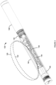
- FIG. 2 is a diagrammatic, partially cutaway view, in perspective, which illustrates an embodiment of transmitter 130.
- the latter includes a main housing 134 that can be at least generally cylindrical in configuration.
- a battery compartment 138 can be formed at one end of the housing with an opposing end 140 supporting a main printed circuit board (PCB) 144 which itself can support an antenna 148 that emits the transmitter signals.
- An accelerometer module 150 can be positioned adjacent to one end of PCB 144.
- Other sensors and components can be located on the main printed circuit board, as will be further described.
- the transmitter includes a processing section 152 that receives sensor information via a multiplexer 154.
- the multiplexer can be interfaced with any number of sensors forming a sensor suite.
- the sensors include accelerometers 158 that are supported in accelerometer module 150 of Figure 2 , a pressure sensor 160 which can be used to sense the annular pressure within the borehole around the transmitter, a temperature sensor 164, a battery current sensor 168 and a battery voltage sensor 170.
- External communication for the transmitter can be provided, in some embodiments, by an external communication connection 174.
- a power supply section 178 can comprise a battery 180 that provides power via an overvoltage and reverse polarity detector 184. The latter provides electrical power to a logic and sensor power supply 188 and to an antenna drive power supply 190.
- the logic and sensor power supply provides power to the sensor suite as well as to processing section 152.
- the antenna drive power supply feeds electrical power to a depth antenna driver 194 and a data antenna driver 198 which electrically drive opposing ends of an antenna coil forming part of antenna 148.
- Drivers 194 and 198 can be half bridge drivers.
- the antenna drivers receive input signals from a processor 200 that forms part of the processing section.
- the processing section further includes an oscillator 210 such as, for example, a crystal oscillator.
- the oscillator can be selected to provide a relatively high degree of temperature and overall stability.
- Processor (CPU) 200 includes a timer section 212 that can serve to generate a reference signal having a stability that reflects the stability of oscillator 210.
- the output frequency of the timer is selectable based on a reload timer value that can be specified by the user.
- the processor is in data communication with a memory 218 which can include any suitable information including, but not limited to depth frequency information 224 and symbol frequency information 228, each of which will be described at an appropriate point hereinafter.
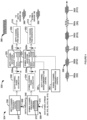
- FIG. 4 an embodiment of a frequency synthesizer is generally indicated by the reference number 300 and is implemented as part of processing section 152 of Figure 3 . It should be appreciated that the frequency synthesizer can be implemented in hardware, software or any suitable combination thereof.
- the embodiment of Figure 4 is a two channel direct digital synthesizer (DDS) having a depth channel 304 and a symbol channel 308.
- the depth channel provides an output signal 310 to depth driver 194 of Figure 3 for producing depth signal 120 while the symbol channel provides an output signal 312 to data driver 198 of Figure 3 for producing data signal 122 ( Figures 1 and 2 ).
- a depth channel waveform lookup table section 320 and a symbol channel waveform lookup table section 324 each includes at least one waveform or phase lookup table that characterizes one period of a selected waveform such as, for example, a sinusoid.
- each of the depth channel lookup table section and the symbol channel lookup table section can include a plurality of waveform or phase lookup tables.
- Each waveform lookup table 326a-n can include a large number of samples of the magnitude of the characterized waveform based, for example, on the amount of memory that is available and the desired resolution.
- the samples are selectively addressable by a depth channel phase accumulator 330 and a symbol channel phase accumulator 334, respectively, using an m-wide addressing arrangement.
- Each phase accumulator is configured to provide an output count to its respective waveform lookup table section based on an input increment or offset size that is provided by a depth channel frequency control 338 and a symbol channel frequency control 340, respectively.
- the particular one of the waveform lookup tables 326a-n to be used at any given time for each of the depth channel and the symbol channel is based on the frequency to be generated, as will be further described.
- Each phase accumulator generates what can be described as a quantized sawtooth waveform output that changes from one level or count to the next by a respective one of the input increment sizes.
- the depth channel lookup table that is currently in use and the symbol channel lookup table that is currently in use sequentially generate digital output magnitudes that are received by a depth channel pulse width modulator (PWM) generator 350 and a symbol channel pulse width modulator (PWM) generator 352, respectively, on an n-wide address arrangement.
- PWM depth channel pulse width modulator
- PWM symbol channel pulse width modulator
- a pulse width modulator Based on the magnitude value received by each PWM generator, a pulse width modulator generates an output pulse train having an at least generally constant output magnitude but with a pulse width that increases in proportion to the output magnitude value from each lookup table. Filtering, via the inductive properties of antenna 148, smooths the waveform to approximate a desired output waveform such as, for example, a sinusoidal waveform.
- each of a depth channel output waveform 360 and a symbol channel output waveform 362 can be generated, for example, across a frequency range approaching 0 Hz to 45 KHz with a high degree of accuracy.
- any suitable frequency range can be utilized and the range of 0 to 45 KHz has been described by way of example and is not intended to be limiting.
- the accuracy can be at least approximately +/-0.1 Hz or less at a resolution of at least approximately 5 Hz. It is noted that the specified accuracy, in the context of the present embodiment, is given for at least approximately 45 KHz which represents a lower limit on accuracy across the frequency range.
- Output frequencies 360 and 362 are established based on the input increment size provided to depth channel phase accumulator 330 via depth channel frequency control 338 and symbol channel phase accumulator 334 via symbol channel frequency control 340.
- Depth channel frequency control 338 receives a depth frequency input 368 that specifies the depth frequency.
- the depth channel frequency control can convert a specified depth frequency to an increment size for depth channel phase accumulator 330 in any suitable manner.
- the depth channel frequency control can include an increment lookup table 370 that indexes depth frequency against the increment size.
- phase accumulator size is chosen to provide the minimum required frequency resolution and the phase accumulator update rate is established by timer 212 ( Figure 3 ).
- symbol channel frequency control can convert a specified symbol frequency received on a data symbol stream input 374 to an increment size for symbol channel phase accumulator 334 in any suitable manner such as, for example, by using an increment lookup table 372 or a formula.
- the origin of the data symbol stream for data symbol stream input 374 will be described at an appropriate point hereinafter. It is noted that there is no requirement for the depth and symbol channel frequency controllers to use an identical increment size lookup table. Table 1 below illustrates a portion of increment lookup table 372.
- Table 1 Desired Output Frequency vs. Phase Accumulator Size Increment Desired Output Frequency (Hz) Phase Accumulator Increment (counts) 5 1 50 10 500 100 32770 6554 45000 9000
- a resolution of 5 Hz can be provided across the entire frequency range extending from worldwide AC powerline frequencies to 45 KHz.
- other embodiments can utilize a like or different resolution to even higher frequencies.
- Other resolutions can be used, some of which are larger and some of which are even more fine, however, Applicants recognize that 5 Hz represents a relatively small common multiple of 50 Hz and 60 Hz which are the predominant powerline frequencies around the world. Further discussions with respect to powerline frequencies will be presented below.
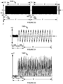
- depth output frequency 360 and symbol output frequency 362 are illustrated as frequency tones that are of a limited or fixed duration, an at least essentially fixed frequency and can include a variable magnitude.
- Magnitude/amplitude shaping can be accomplished using a depth channel waveform/amplitude control 380 for the depth channel which may be referred to as a depth channel shaper and a symbol channel waveform/amplitude control 382 which may be referred to as a symbol channel shaper.
- Another example output of depth channel PWM generator 350 is a continuous depth signal 386 which is of at least essentially a continuous magnitude.
- depth channel shaper 380 may not be needed, although it should be understood that its operation reflects the operation of the symbol channel shaper, as described herein.
- output 390 of symbol channel PWM generator 352 illustrates a series of output symbols indicated as 392a-392f which can vary in frequency from one symbol to the next.
- output 390 comprises a symbol stream.
- the frequency can change abruptly from one symbol to the next in a way that can introduce noise responsive to such abrupt frequency transitions.
- symbols 392a-392f are shaped in a way that avoids abrupt frequency transitions by beginning and ending at a value of approximately zero magnitude. Such shaping can be accomplished through the application of a suitable window or tapering function by symbol channel shaper 382 such as, for example, a Hamming window, Hann window, Welch window or a triangular window, among others. What is common to all of the subject window functions resides in a zero magnitude of the waveform for any point that is outside of a window interval such that each symbol starts and ends with a zero magnitude waveform.
- transmitter 130 can be configured to transmit depth signal 120 and data signal 122 using a series of transmitter bands, generally indicated by the reference number 400 that extend from approximately 0 to 45 KHz. It should be understood that other embodiments can use different transmitter bands and sub-bands with the present embodiment serving by way of a non-limiting example. While the value of zero is listed as a lower limit, it should be understood that the actual lower limit can be represented by worldwide predominant power line frequencies or some higher value.
- the transmitter bands are indicated as BT1-BT5 and are also set forth in Table 2.
- Sub-Band Frequency Range BT1 0- 4.5 KHz SB1 0 to 4.5 KHz BT2 4.5 KHz- 9 KHz S82 4.5 KHz to 9 KHz BT3 9 KHz- 18 KHz SB3 9 KHz to 13.5 KHz SB4 1 3.5 KHz to 18 KHz BT4 18 KHz- 31.5 KHz SB5 18 KHz to 22.5 KHz SB6 22.5 KHz to 27 KHz SB7 27 KHz to 31.5 KHz BT5 31.5 KHz- 45 KHz SB8 31.5 KHz to 36 KHz SB9 36 KHz to 40.5 KHz SB10 40.5 KHz to 45 KHz
- the frequency range from 0 to 45 KHz is further divided into 10 sub-bands SB1-SB10, each of which is 4.5 KHz in width.
- Each band above BT1 and sub-band 1 can be considered as including its lower frequency limit.
- any individual transmitter can be configured for transmission in one of transmitter bands BT1-BT5.
- the use of the transmitter bands although not required, allows for matching antenna 148 ( Figure 2 ) to the transmitter band such that transmission efficiency is at least near optimal.
- transmitter bands BT1 and BT2 each include a single sub-band
- transmitter band BT3 includes two sub-bands, SB3 and SB4
- transmitter bands BT4 and BT5 each include three sub-bands: SB5-SB7 and SB8-SB10, respectively.
- An embodiment of a transmitter according to the present disclosure can be configured to transmit depth signal 120 and data signal 122 in a single sub-band.
- a transmitter can be configured to transmit depth signal 120 in a sub-band that is different from the sub-band that is used for data signal 122.
- a transmitter can be configured to transmit on multiple sub-bands.
- a transmitter configured to transmit on transmitter band BT3 can transmit on both SB3 and SB4.
- a wideband transmitter as further described below, can transmit on two or more sub-bands, such as SB4 and SB10 such that the sub-bands can even be spaced apart by other sub-bands.
- SB4 and SB10 sub-bands
- transmitter 300 can be configured to cooperate with antenna 148 such that transmitter 130 transmits over a wide frequency range or band extending from a lowermost frequency to approximately 45 KHz or higher. In this way, this wide frequency band can be covered by a single wideband transmitter, using a single antenna, while maintaining suitable efficiency with respect to power consumption across the entire wide frequency range. It should be appreciated that, in the absence of the provisions described immediately hereinafter for at least part of the wide frequency range, an unmatched condition between the antenna and the input frequency can produce unacceptable battery power consumption to achieve the same RF output power.
- depth channel lookup table section 320 and symbol channel lookup table section 324 can be configured to include sets of lookup tables 326a-n. Any suitable number, n, of lookup tables can be used in each set.
- Depth channel phase accumulator 330 and symbol channel phase accumulator 334 can be configured to utilize the appropriate depth channel lookup table and symbol channel lookup table, respectively, based on the frequency to be generated.
- each individual lookup table of these sets of lookup tables can be customized to drive antenna 148 in a way that maintains power at an at least generally constant power consumption over a portion of the overall wide transmission bandwidth such that the combination of lookup tables maintains a desired level of power consumption over the entire wide transmission bandwidth.
- Each lookup table can be configured for driving the antenna not only based on providing a particular wave shape but also using a selected drive waveform magnitude. Accordingly, transmission power and transmitter power consumption can be controlled or regulated, at least in part, based on the magnitude of the lookup table waveform.
- a high output power lookup table can exhibit the same sampled waveform shape as a corresponding lower power lookup table, but the high power lookup table includes an increased magnitude version of the sampled waveform.
- the antenna in the embodiments presented herein, is not required to be driven at a resonant frequency.
- the resonant frequency that is presented by the inductance of antenna 148, in combination with any parasitic capacitances is generally far higher than a highest frequency of the transmission range such as, for example, 45 kHz.
- the resonant frequency can be in the megahertz range.
- the antenna can exhibit an impedance across the transmission frequency range that can be considered as a constant, at least from a practical standpoint.
- antenna 148 can include a number of windings that is selected based, at least in part, on a selected or targeted amount of current draw from battery 180.
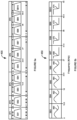
- Figure 5b illustrates an embodiment of a set of lookup tables, generally indicated by the reference number 450, that can be used for the depth and symbol frequency lookup tables 326a-n.
- the set comprises 8 lookup tables.
- the lookup table set covers SB3 through SB10, corresponding to a wideband frequency range of 9 KHz to 45 KHz. While the wide frequency range is characterized in terms of sub-bands for purposes of descriptive continuity, it should be appreciated that there is no need for frequency confinement based on the previously described transmitter bands and/or sub-bands (see, for example, Table 2) in the context of a wideband transmitter.
- Figure 5b illustrates general lookup table waveform shapes 460, 462, 464, 466, 468, 470, 472 and 474 that are used for each sub band SB3-SB10, respectively.
- SB3-SB6 a sinusoidal sampled waveform is used.
- SB7-SB10 a stepped sampled waveform is utilized. Further details will be provided immediately hereinafter.
- Figures 5c-5j illustrate further enlarged plots of lookup table sampled waveforms 460, 462, 464, 466, 468, 470, 472 and 474, respectively, for the present embodiment of the set of lookup tables for purposes of depth and data transmission.
- the horizontal axis of each of these figures illustrates the sampled waveform period or time slot, while the vertical axis designates a Pulse Width Modulation percentage. It is noted that the actual duration of the sampled waveform period is limited to 0-15 on the time slot axis shown in each of these figures.
- waveform 460 includes a sinusoidal shape having a PWM percentage that ranges from approximately 15% PWM to 85% PWM.
- waveform 462 includes a sinusoidal shape having a PWM percentage that ranges from approximately 10% PWM to 90% PWM.
- waveform 464 includes a sinusoidal shape having a PWM percentage that ranges from approximately 5% PWM to 95% PWM.
- waveform 466 includes a sinusoidal shape having a PWM percentage that ranges from approximately 0% PWM to 100% PWM.
- a stepped sampled waveform is utilized wherein the waveform transits from 100% PWM to 0% PWM.
- the on-time of the waveform is approximately 20%.
- the use of sampled waveform 468 generates a pulse train as an antenna drive signal with an on-time of approximately 20%.
- the on-time of the waveform is approximately 27%.
- the use of sampled waveform 470 generates a pulse train as an antenna drive signal with an on-time of approximately 27%.
- the on-time of the waveform is approximately 33%.
- sampled waveform 470 generates a pulse train as an antenna drive signal with an on-time of approximately 33%.
- the on-time of the waveform is approximately 50% corresponding to a square wave.
- the use of sampled waveform 470 generates a pulse train as an antenna drive signal with an on-time of approximately 50%.
- Lookup table waveform 474 of Figure 5j for SB10 drives the antenna using a square wave at the fundamental of the frequency that is to be transmitted. In doing so for the higher frequencies, the amplitude of the fundamental, as a first harmonic component of the square wave, is higher by about 2 dB than the amplitude of a pure sinewave of a corresponding power.
- Figures 5i and 5h demonstrate that the on-time of waveforms 472 and 470 progressively decreases. Accordingly, as the transmit frequency becomes lower, the drive waveform becomes more pulse-like to progressively lower the amount of energy at the fundamental frequency of the pulse train.
- the power that is drawn by the transmitter is compensated and does not significantly increase with decreasing transmit frequency.
- This pulse train drive signal approach is employed until a sinewave drive signal of at least approximately full magnitude matches the available transmit power from a pulse train drive signal.
- Such a condition is satisfied at SB6 which utilizes sinewave-shaped lookup table waveform 466.
- the magnitude of the sinewave drive waveform is further reduced in order to compensate for the tendency of transmit power to increase responsive to decreasing transmit frequency.
- lookup table approach developed by Applicants, which is submitted to be heretofore unknown, provides for varying the drive frequency over a wideband transmit range using a single antenna and without the need for using different antennas which would necessitate the use of multi-coil antennas, complex antenna coil switching and/or complex variable drive voltage arrangements.
- the present disclosure can provide a wideband transmitter having a single antenna that is driven across a wide frequency band in a way that can maintain constant or controlled power consumption, at least to an approximation, when the power consumption would otherwise exhibit large variations across that same frequency band by using a single drive signal waveform.
- Variation in the power consumption across the wide frequency band can be limited to acceptably low levels across the range of 9 KHz to 45 kHz.
- Applicants are able to provide a wideband transmitter that operates across a wide frequency range with power consumption regulation and control that is submitted to have been unseen heretofore.
- the symbol channel can be set up to output a single carrier frequency, much like depth signal 386 of the depth channel, and that carrier frequency can be modulated in any suitable manner, for example, to carry sensor data based, at least in part, on the set of lookup tables 326.
- a relatively low frequency such as, for example, 1.5 kHz
- a modulated data frequency at a much higher frequency such as, for example, in the range of 30 kHz to 45 kHz.
- a factor of 20 or more can be provided between the modulated carrier frequency and the depth tone as a result of the remarkable frequency generation capabilities of a transmitter that is produced in accordance with the present disclosure.
- low depth tone frequencies are associated with avoiding sources of passive interference such as rebar while higher data frequencies are associated with higher rates of data throughput based on the Nyquist rate.
- the present disclosure allows for the transmission of a depth tone that is spaced apart from a modulated data frequency by an amount that is submitted to be heretofore unseen, particularly when a single antenna is used to transmit both.
- the depth tone can be transmitted at 1.5 kHz or less and the modulated data frequency can be transmitted in the range from 30 kHz to 45 kHz.
- 10 kHz can be used for the depth tone while 40 kHz can be used for the modulated data frequency.
- the data signal can serve to transmit a multi-bit symbol stream.
- the ability to transmit a multi-bit symbol stream is facilitated, at least in part, based on the use of synthesizer 300 of Figure 4 .
- a multi-bit data symbol stream can be provided at data symbol stream input 374 to symbol channel frequency control 340.
- the data symbols of the symbol stream can correspond to 16 symbols (4 bits), although any suitable number of symbols can be used, based on a desired data throughput.
- Figure 4 illustrates output 390 based on 16 symbols, S0-S15, with S0 corresponding to a lowest frequency and each successively higher-numbered symbol corresponding to a relatively higher frequency, although this is not required and the mapping or assignment of symbols to frequencies can be performed in any suitable manner.
- output 390 corresponds to an example input symbol stream of S2, S12, S2, S15, S0 and S10 at input 374.
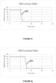
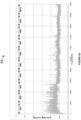
- Figure 6a is a plot of the power spectral density of noise taken at a high resolution, generally indicated by the reference number 500, corresponding to an actual physical location at which a 50 Hz powerline frequency is in use.
- the signal level is shown on the vertical axis and the frequency is shown on the horizontal axis.
- the frequency range of 0 to 45 KHz corresponds to the frequency range that is covered by the range of transmitters described in accordance with the present disclosure, for example, with regard to Figure 5a .
- the present embodiment utilizing the range of 0 to 45 KHz, has been provided by way of non-limiting example.
- Transmitter sub-bands SB1-SB10 are also indicated.
- An initial choice of which sub-band is most suitable can be based on a determination of an average noise value per sub-band. On this basis, any one of sub-bands SB8-SB10 appears to represent an acceptable choice while one of sub-bands SB1-SB3 appears to represent the worst choice.
- spectral scan of Figure 6a illustrates spectral information essentially at a single location
- spectral information can be collected in a cumulative manner.
- spectral scanning can be performed while an operator walks the planned borepath with device 20 while the device characterizes the noise environment.
- the spectral plot of Figure 6a can be thought of as representing the noise environment along the entire planned borepath with subsequent frequency selections being based on the noise environment as characterized for the entire length of the planned borepath while still utilizing the frequency selection techniques that have been brought to light herein.
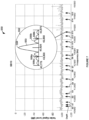
- FIG 7 is a further enlarged view of sub-band 10 from Figure 6a , generally indicated by the reference number 550, and is shown here to illustrate the selection of a depth frequency and sixteen symbol frequencies S0-S15 within this sub-band. Each selected frequency has been designated by an arrow. The various frequencies have been selected, for example, based on their correspondence to low noise points in the noise plot. Based on the selection of frequencies, such as S0-S15 either automatically and/or manually, Applicants submit that system 10 can provide a level of noise immunity that has heretofore been unseen with respect to performing an inground operation such as, for example, horizontal directional drilling and related pull-back or back-reaming operations. Related considerations and further details will be provided in the context of a discussion of device 20 which receives the depth signal and the data signal and which also can assist in the identification of the depth signal frequency and symbol frequencies to be used by the transmitter.
- the harmonics are at least generally spaced apart by 50 Hz and can extend to values upwards of 30 KHz. Therefore, powerline harmonic noise can be reduced by choosing symbol frequencies that fall at least between or halfway in between the powerline harmonics.
- symbol frequencies in the series 75 Hz, 125 Hz, 175 Hz, 225 Hz, and so on can be selected while, for a 60 Hz powerline frequency, symbol frequencies in the series 90 Hz, 150 Hz, 210 Hz, 270 Hz, and so on can be selected.
- the subject symbol potential frequencies may be referred to herein as the in-between frequencies.
- synthesizer 300 can be configured with a frequency resolution of 5 Hz such that any desired in-between harmonic frequency of 50 Hz or 60 Hz can be selected as a symbol frequency.
- synthesizer 300 can be configured to allow for frequency selection at a resolution of 5 Hz.
- this level of resolution provides for frequency selection that is half way between adjacent powerline harmonics.
- the bandwidth between adjacent harmonics is at least approximately 50 Hz.
- the bandwidth between adjacent harmonics is at least approximately 60 Hz. Due to the stability with which the symbols are generated in conjunction with symbol shaping as seen in Figure 4 , the symbols transmitted to make up the symbol stream of data signal 122 can exhibit limited spectral spreading. Further, the spectral spreading that is present can exhibit a particular relationship with adjacent powerline harmonics based on transmission rates.
- an inset view 552 in Figure 7 includes a plot 553 that illustrates the spectral content of symbol S13 in Hertz relative to its nearest powerline harmonics.
- the fundamental frequency of S13 is 43,825 Hz which is half way between adjacent 50 Hz powerline harmonic frequencies of 43,800 Hz and 43,850 Hz.
- a fundamental peak 554 is present in the spectral plot of the symbol at 43,825 Hz such that all of the spectral energy of this peak falls between the adjacent powerline harmonics.
- Side lobes 556a and 556b also fall entirely between the adjacent powerline harmonics. It is noted that several additional side lobes are shown having energy that falls outside of the adjacent powerline harmonics at 43,800 Hz and 43,850 Hz.
- the spectrum of the symbol exhibits nulls 558a and 558b that fall directly on the adjacent powerline harmonic frequencies.
- the spectral content of each symbol frequency effectively places no signal power on the adjacent powerline harmonics.
- the nulls are positioned to fall on the adjacent powerline harmonics, as shown in Figure 7 , based on the data transmission rate of the symbol stream.
- symbol stream 390 is transmitted without gaps between the symbols.
- additional side lobes will likewise be separated by nulls that are located directly on powerline harmonic frequencies such as, for example, 43,750 Hz and 43,900 Hz, which have not been shown due to illustrative constraints.
- the symbol spectra includes a null positioned at every powerline harmonic frequency. It is noted that an additional portion of the spectral energy that is associated with each symbol can be moved between adjacent powerline harmonics.
- Table 3 provides at least approximate values for each of the selected frequencies shown in Figure 7 .
- the reader is reminded that frequencies S0-S15 were selected on the basis of exhibiting low noise, as opposed to attempting to avoid power line harmonics.
- Table 3 also lists a nearest powerline harmonic based on a 50 Hz powerline frequency. In some instances, such as with respect to the frequency choices for S1, S4, S7 and S8, it appears that these frequencies correspond to a 50 Hz powerline harmonic while, in other cases, the frequency choices only for the depth signal, S5 and S13 fall on in-between harmonic frequencies. In this regard, it should be appreciated that such shifting of low noise points in the noise spectrum can result from powerline frequency drift, as discussed above.
- system 10 can provide a level of noise immunity that has heretofore been unseen with respect to performing an inground operation such as, for example, horizontal directional drilling and related pull-back or back-reaming operations.
- an inground operation such as, for example, horizontal directional drilling and related pull-back or back-reaming operations.
- device 20 which receives the depth signal and the data signal and which also can assist in the identification of the depth signal frequency and symbol frequencies to be used by the transmitter.
- the depth signal frequency and symbol frequency ordering given by Table 3 are not required. That is, the depth signal frequency can be positioned between symbol frequencies. Based on the use of a separate channel for purposes of generating the depth signal ( Figure 4 ), the depth signal can be positioned in a different sub-band than the symbol frequencies.
- the symbol frequencies can be reordered or rearranged in any suitable manner.
- constraining frequency selection to a single sub-band it should be understood that an embodiment of a wideband transmitter can be configured to operate in a manner that mimics the operation of a transmitter that is constrained to operate based on sub-bands.
- the selected frequencies in a wideband transmitter can be limited or constrained to a single sub-band, even though the wideband transmitter is capable of transmission over a wide range of sub-bands.
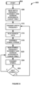
- FIG 8 is a flow diagram that illustrates an embodiment for the operation of a transmitter, generally indicated by the reference number 600, according to the present disclosure. It is noted that, for purposes of the present discussion, it will be assumed that the depth frequency as well as the frequencies associated with symbols S0-S15 have already been selected. These frequency choices can be stored at any suitable location such as, for example, in depth frequency table 224 and symbol frequency table 228 of Figure 3 .
- the method begins at 604 and proceeds to 608 which looks up the depth frequency increment, for example, from lookup table 370 ( Figure 4 ) as part of the operation of depth channel frequency control 338.
- step 608 also can identify the correct waveform lookup table 326a-n as part of depth channel waveform tables section 320 in Figure 4 such that depth channel phase accumulator 330 addresses the appropriate depth channel lookup table waveform based on frequency.
- depth channel phase accumulator 330 receives the value and begins counting based on the depth frequency increment, thereby causing the appropriate depth channel lookup table 326a-n and depth channel PWM generator 350 to begin continuously generating depth channel frequency 386 to emit depth signal 120 at this frequency.
- depth channel phase accumulator 330 receives the value and begins counting based on the depth frequency increment, thereby causing the appropriate depth channel lookup table 326a-n and depth channel PWM generator 350 to begin continuously generating depth channel frequency 386 to emit depth signal 120 at this frequency.
- CPU 200 reads sensor information via multiplexer 154 to collect sensor data that is to be transmitted.
- the CPU assembles the sensor data into a symbol stream which can invoke a packet structure that is yet to be described.
- the symbol stream is provided as data stream symbol input 374 to symbol channel frequency control 340 in Figure 4 .
- the symbol channel frequency control can utilize its lookup table 372 to identify the appropriate frequency for a current symbol to be transmitted.
- symbol channel phase accumulator 334 can always address that single waveform lookup table.
- step 620 also can identify the correct waveform lookup table 326a-n as part of symbol channel waveform tables section 324 in Figure 4 such that symbol channel phase accumulator 334 addresses the appropriate symbol channel lookup table waveform. It should be appreciated that the transmission of a given symbol stream can necessitate that step 620 switches data waveform lookup tables 326a-n on a symbol-by-symbol basis from one symbol to the next, based on frequency.
- the current symbol is transmitted. Step 624 checks for the availability of another symbol to transmit. If a symbol is available, operation returns to 620 such that the process repeats for the next symbol.
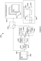
- Device 20 includes a battery 700 that feeds a power supply 704 which supplies appropriate electrical power to all of the components of the device, indicated as V+.
- Electronics section 32 includes a processor 710 that is interfaced with a memory 714.
- a telemetry section 720 is controlled by the processor and coupled to antenna 40 for bidirectional communication via signal 44.
- the telemetry link can be unidirectional from device 20 to the drill rig, in which case transceiver 102 need only include receiver functionality.
- An external communication arrangement 722 provides for external communication with a transmitter using external communication connection 174 ( Figure 3 ) of the transmitter. As discussed above, such communication is not required to be transmitted through the ground but rather can be performed while the transmitter is above ground, for example, in a position adjacent to device 20.
- the external communication can be implemented in any suitable manner including but not limited to IrDA, NFC, Wi-Fi, Zigbee or Bluetooth.
- a wide-band front end 730 is configured for receiving depth signal 120 and data signal 122 using X, Y and Z antennas which make up antenna cluster 26 for measuring three orthogonal components of the subject signals as well as for performing noise measurements along these axes, as is yet to be described. Additional details with respect to an embodiment of the antenna cluster will be provided at an appropriate point hereinafter.
- Each of the X, Y and Z antennas is interfaced to a low noise amplifier (LNA) 734a, 734b and 734c, respectively, each of which can be identically configured.
- the amplified output of each LNA is supplied to a respective one of filters 738a, 738b and 738c, each of which can be configured identically and which may be referred to collectively as filters 738.
- Each filter serves as a bandpass filter 740 exhibiting a low frequency roll-off or corner and a high frequency roll-off or corner. While filters 738 are illustrated as individual functional blocks, it should be appreciated that the filters can be implemented in any suitable manner.
- each filter can be implemented as a series of RC high-pass and low-pass filters that are distributed throughout the signal chain.
- two high-pass filters can each be set at a low corner frequency of about 4 KHz and four low pass filters can be set at a high corner frequency of about 90 KHz.
- This embodiment yields a relatively flat frequency response from 10 KHz to 50 KHz.
- the roll-off below 10 KHz is approximately 40 dB of attenuation per decade and the roll-off above 50 KHz is approximately 80 dB of attenuation per decade.
- the low end response of filters 738 and the low corner frequency can be established in consideration of the fundamental and low order power line harmonics, which can be very strong.
- Amplifiers 750a-750c can follow each respective one of filters 738a-738c with sufficient gain for purposes of driving each of analog-to-digital converters A/D 754a-754c.
- Each A/D 754 provides an output to CPU 710.
- device 20 can be configured to receive the symbol stream in a way that suppresses powerline harmonic frequencies since there is effectively no energy present in the symbol stream at the powerline harmonics.
- the received signal can be processed such that the receiver response matches the symbol spectra as illustrated by plot 553 of Figure 7 .
- the spectral response of the receiver can be matched to the spectral characteristics of the transmitter by integrating the received symbol stream over a time period that corresponds to the time duration or period of each symbol.
- the receiver frequency response matches the response of the transmitter with respect to exhibiting null reception points at the powerline harmonic frequencies. Accordingly, energy at the harmonic frequencies is suppressed or ignored by the receiver while sweeping up the spectral energy that is associated with the symbol.
- the receiver can employ any suitable demodulation process that provides periodic nulls including but not limited to a Discreet Fourier Transform (DFT).
- DFT Discreet Fourier Transform
- the locator can be configured for performing noise measurements and analysis for purposes of selecting a transmitter for transmission of the depth signal and the data signal as well as establishing the frequencies to be associated with each of these signals.
- band selection may not be required when a wideband transmitter is used.
- Noise measurements can be determined based on each orthogonal axis of antenna 26 (X, Y and Z antennas, as shown in Figure 9 ). These individual noise components can be used to establish a three dimensional noise value, for example, based on a vector sum of the three antenna components. The vector sum can be useful since the noise reading at a given point will essentially be invariant with changes in the orientation of the locator.
- Noise values can be determined in any suitable manner such as, for example, based on a Fast Fourier Transform (FFT).
- FFT Fast Fourier Transform
- a noise scan can be produced from each axis for comparative purposes. For example, an axis that exhibits relatively higher noise than the other axes can be handled differently for purposes of data recovery.
- an initial choice of which sub-band is most suitable can be based, for example, on an average noise value per sub-band.
- the locator can automatically make a recommendation to use the lowest average noise sub-band such as, for example, SB-9.
- display screen 36 can illustrate a plot, bar graph or any suitable form of display format based on the spectral scan of Figure 6a , highlighting the selected sub-band.
- the sub-band selection process can involve other statistical values for purposes of characterizing the noise, as will be described immediately hereinafter.
- Figure 6b illustrates one embodiment of a screen shot showing display 36 including a bar graph display illustrating the average noise per sub-band wherein sub-band SB-10 is highlighted, for example, using hatching and/or color or in some other suitable manner to indicate that SB-10 has been automatically selected.
- the locator can make an automatic recommendation based on average noise per sub-band in conjunction with other statistical values. Any suitable statistical value(s) can be utilized including, for example, standard deviation, minimum noise and peak noise.
- more than one sub-band can be recommended, in which case the user can select between the recommended sub-bands. Recommending multiple sub-bands can be based on a limited amount of statistical variation between the sub-bands.
- sub-bands 9 and 10 can both be recommended based on the relatively limited difference between the two sub-bands, as seen in Figure 6b .
- multiple sub-bands can be recommended, for instance, based on the average noise for a first sub-band being lower than the average noise for a second sub-band while the peak noise for the first sub-band is higher than the peak noise for the second sub-band.
- the system can be configured such that the user can select one of such multiple recommended sub-bands for transmission.
- the user can select multiple recommended sub-bands for transmission.
- one or more of such multiple recommended sub-bands can be automatically selected for transmission.
- the standard deviation of the noise values within each sub-band can be determined.
- the heights of the various bars in Figure 6b can be weighted by adding or subtracting a value based on one or more other statistics. For example, if the standard deviation for a given sub-band is high, meaning that the noise values are relatively more widely spread out, the height of the associated bar can be maintained or even increased by some amount. On the other hand, if the standard deviation for a given sub-band is low, meaning that the noise values within that sub-band are relatively consistent, the height of the associated bar in Figure 6b can be lowered.
- the heights of the bars in the bar graph can be weighted based on peak noise such that a sub-band having a high peak noise can be increased in height by some amount.
- weighting can be performed based on thresholds for the respective statistical values. Weighting can be applied based on individual statistical values or combinations of statistical values.
- the automatically selected sub-band can be accepted by the operator touching an Auto-Select button 780 or by touching any sub-band which he or she wishes to choose. The operator can override the automatic selection, for example, based on which specific transmitters are currently available for performing the inground operation. As another basis to present information to the operator, other statistical values can be presented.
- overbars 781 show the peak noise per sub-band.
- the operator may choose to avoid a sub-band that exhibits a particularly high peak noise level, even if the average noise for that sub-band is relatively low.
- the operator can touch a Manual Select button 782 and then touch a sub-band which he or she wishes to choose.
- display 36 on the locator can display a plot, bar graph or any suitable form of display format that is derived from the spectral scan that is shown in Figure 6a such that the operator is then allowed to manually select one of the sub-bands, for example, by touching the sub-band of choice on the display screen.
- locator 20 can allow the operator to initially enter information relating to the transmitters that are available for automatic selection of a sub-band that is covered by one of those transmitters, excluding sub-bands that are not available, in a manner that is consistent with the teachings of
- FIG. 6b illustrates sub-bands that are not available, based on unavailable transmitters, using dashed lines. Conversely, solid lines indicate sub-bands that are available. In the present example, SB-1 and SB-5 through SB-7 are not available. In an embodiment, sub-bands can be excluded based on regulatory constraints. In this way, the portable device itself and the operator are not allowed to make frequency selections that would violate regulations in a particular jurisdiction. Such frequency restrictions can be predetermined by the manufacturer on a regional basis. In an embodiment, portable device 20 or some other component of the system such as, for example, drill rig 80 can be equipped with a GPS receiver that can establish the location of the inground operation and then look up the local frequency requirements.
- a GPS receiver can establish the location of the inground operation and then look up the local frequency requirements.
- the display screen that is shown can remain "live" at least until the frequency selection process is completed. That is, the average noise per sub-band can be monitored and displayed, either alone or weighted by other statistical parameters, in real time for operator monitoring purposes. In this way, the operator can move the locator about while observing the average noise in the various sub-bands. For example, the operator can walk a planned borepath and monitor the noise along the borepath prior to beginning drilling. In this way, a sub-band that is particularly noisy at one or more points along the borepath can be avoided.
- the operator can move the locator to a different point, for example, along the borepath and initiate a rescan of the noise across the entire bandwidth by selecting a rescan button 784.
- the noise environment can be characterized based on reception using one or more antennas.
- the operator can change the receiving mode using a button 786.
- the bar chart of Figure 6b can be presented based on reception along a single axis such as, for example, the X axis.
- the bar chart can be presented based on a vector sum produced from three orthogonal receiving axes.
- rescan button 784 can initiate a new noise scan and present the noise values based on the selected receiving mode.
- the operator can switch between the various noise scanning modes at will.
- the noise scan that forms the basis for the display of Figure 6b can be a high resolution scan.
- a number of optimized, low noise frequencies can be selected automatically based on the number of symbol frequencies that is needed. For example, sixteen symbol frequencies and a depth frequency can be selected per sub-band.
- noise per sub-band can be presented as an average of the noise values measured at each of the selected frequencies within each sub-band.
- Locator 20 can be configured to store sets of frequency selections that are associated with different measurement positions, for example, in memory 714 of Figure 9 . Accordingly, the frequency selections are optimized for each measurement position such that different selections can be used at different times during the operation.
- the term "optimized" is intended to mean that the selected frequencies are chosen with the intent of avoiding interference based on one or more statistical parameters such as, for example, average noise, standard deviation and peak noise.
- the frequency selection sets can be communicated to the transmitter, for example, above ground using external communication connection 174 of Figure 3 .
- An inground transmitter can be commanded in any suitable manner to switch to a different set of frequency selections during the inground operation. For example, switching can be commanded based on a predetermined roll sequence of the drill string or by transmission of an electromagnetic signal from above ground for reception by transmitter 130 which is, in this case, configured as a transceiver.
- transmitter 130 which is, in this case, configured as a transceiver.
- Some embodiments can use the drill string as an electrical conductor or can include a well-known wire-in-pipe arrangement such that data can be transmitted between the inground transmitter/transceiver and the drill rig.
- the drill rig can send a command via the drill string to cause the depth frequency to change.
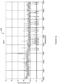
- Figure 10a is an expanded view of sub-band 6 from Figure 6a , generally indicated by the reference number 800.
- the frequencies for depth signal 120 and data signal 122 can be established.
- the frequencies can be predetermined, for example, by the manufacturer or based on a previous noise scan, as described above.
- display 36 can be used to represent the spectral plot of Figure 10a , in any suitable form, to an operator of the locator such that the operator can make frequency selections.
- Figure 10b illustrates one embodiment of a screen shot which shows display 36 illustrating SB-6.
- the locator can provide a zoom function on display 36 that uses Zoom In button 802 and Zoom Out button 804 such that the operator can expand the horizontal extents of the spectral display to provide for detailed frequency selection.
- the operator can select frequencies that correspond to low noise points on the displayed spectrum.
- the selections can be rounded to reflect the frequency resolution of the transmitter that is to be used.
- embodiments of transmitters according to the present disclosure can have a frequency resolution of 5 Hz, by way of non-limiting example. Twenty-one low noise points are identified on Figure 10a indicated as upticks (a)-(u). In an embodiment using one depth frequency for depth signal 120 and 16 symbol frequencies, seventeen of these 21 frequencies can be utilized.
- the depth frequency can be located at any position within the sub-band, intermingled with the symbol frequencies, at either end of the sub-band or even in a different sub-band.
- the depth frequency can be selected as the lowest noise point among the identified frequencies, which is frequency (j) in the present example.
- the frequencies can be automatically picked or re-picked by locator 20, for example, responsive to the operator selecting an "Auto-Pick" button 806 on display 36.
- processor 710 can examine the spectrum of Figure 6a to identify the lowest noise points until a suitable number of symbol frequencies is available.
- the processor can perform the selection process based on any suitable method. For example, the lowest noise frequencies can be selected in conjunction with maintaining a minimum separation between adjacent frequencies.
- a frequency can be added, for example, by touching an Add Frequency button 808 and then touching the spectral plot.
- a frequency can be deleted, for example, by touching a Delete Frequency button 810 and then touching the frequency to be deleted.
- a frequency can be moved, for example, by touching a Move Frequency button 812 and then touching and dragging the frequency to be moved.
- the selected sub-band can be changed by touching a Change Sub-Band button 814.
- frequency selection is not limited to identification of low noise points but also can consider high noise points or areas of the spectral scan.
- Figure 11 is a further expanded view of the spectral region of Figure 10a from 24 KHz to 25 KHz, generally indicated by the reference number 820 and shown here for purposes of describing further details with respect to frequency selection.
- processor 710 can apply what can be referred to as a "keep-out region". The later will exclude any identified low noise frequency having a noise peak within a selected frequency window 822 that is centered on that low noise frequency.
- the noise can be identified, for example, based on a magnitude that exceeds a threshold 824 based on the average noise value for the sub-band and/or the noise value associated with the nearby low noise point.
- the frequency window can be approximately 60 Hz (+/- 30 Hz) in width and the threshold can be 10 dB or more above the associated low noise point. Based on the use of such a frequency window, frequencies (b) and (e) can be excluded due to the proximity of peaks 826 and 830, respectively. In the event that more frequencies are needed, processor 710 can re-examine the spectrum of Figure 11 for purposes of identifying a new set of frequency candidates.
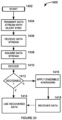
- Figure 12 is a flow diagram that illustrates an embodiment of a method, generally indicated by the reference number 900, for the operation of locator 20 in performing spectral scanning and frequency assignment in accordance with the present disclosure.
- the method begins at 904 and proceeds to 908 which performs a scan of the full frequency spectrum, for example, from 0 Hz to 45 KHz for the present embodiment, although any suitable range can be used for this scan.
- the scan can be a high-resolution scan, for example, utilizing a resolution of 5 Hz, as discussed above.
- an initial, lower resolution scan can be utilized such that the resolution is just sufficient to establish an average noise value for each sub-band.
- a high resolution spectral scan can subsequently be performed as part of the frequency selection procedure, described below.
- a wideband transmitter will be used for the inground operation
- a single high resolution scan can be employed for frequency selection purposes.
- the average noise value per sub-band is determined.
- a sub-band can be recommended based on the average noise values.
- the sub-band having the lowest average noise value can be recommended, although other embodiments can utilize different recommendation protocols.
- the sub-band having the lowest noise peak value can be recommended.
- more than one sub-band can be recommended.
- user input can be requested on display 36 wherein the user can accept the recommended sub-band or choose a different sub-band.
- the user may choose a different sub-band based on an awareness of transmitters that are available for performing the inground operation. As discussed above, this information can serve as an initial input such that method 900 excludes sub-bands that are not covered by the currently available transmitter(s).
- the method proceeds to 920 which determines the sub-band frequencies.
- the sub-band frequencies can be predetermined and stored in memory 714 of the locator or in memory 218 of the transmitter.
- the sub-band frequencies can be determined by the operator on-the-fly by presenting the sub-band on display 36, as discussed above.
- the sub-band frequencies can be determined automatically in accordance with the discussions relating to Figures 10 and 11 with or without the application of a keep-out window as applied by step 924.
- steps 910 and 914 are not required since the entire transmission bandwidth can be available for frequency selection without the need to confine the frequencies to any particular sub-band(s) and step 920 can allocate frequencies across the entire transmission bandwidth. Accordingly, transmission frequencies can be selected automatically across the entire available bandwidth and/or customized by the user based on a high resolution noise scan without the need for frequency assignment limitations based on sub-bands.
- an embodiment of a wideband transmitter can be configured to operate, for example, based on operator preference, using sub-bands in the same manner as sub-band limited transmitters wherein frequency assignment can be confined to one or more sub-bands, although this is not required.
- a determination is made as to whether a sufficient number of frequencies have been identified. If not, operation returns to 920 for identification of additional frequencies. If a sufficient number of frequencies have been identified, operation proceeds to 930 which recommends frequencies for depth signal 120 and data signal 122. This latter step may be optional in a fully automated embodiment.
- information can be presented on display 36 for purposes of gathering user input, for example, approving the frequency selections or changing the frequency selections.
- the user may prefer to move the depth frequency to a different location within the sub-band or to an altogether different sub-band.
- the frequency selections can be transferred to transmitter 130 using external communication arrangement 722 of the locator and external communication link 174 ( Figure 3 ) of the transmitter. Normal operation can then be entered at 940.
- the number of frequencies that is selected can be based on the noise environment. For example, if a noise scan, whether sub-band limited or not, shows a low noise environment, relatively more frequencies can be selected. In this case, 32 or more symbol frequencies can be used instead of 16 symbol frequencies. If the noise scan shows a high noise environment, relatively fewer symbol frequencies can be used such as, for example, 4 or 8 symbol frequencies instead of 16 frequencies. Generally, the use of relatively fewer frequencies can aid in avoiding variable noise sources in a high interference environment. On the other hand, using a higher number of symbol frequencies can increase data throughput.
- Figure 13 is a flow diagram illustrating an embodiment of a method for operation of locator 20 in a normal mode during an inground operation, generally indicated by the reference number 1000.
- the method begins at 1004 and proceeds simultaneously along a depth determination branch 1010 and a data recovery branch 1012.
- Depth branch 1012 receives depth signal 120 at 1020 and then determines the depth of the transmitter at 1024. Because the depth signal is transmitted on a dedicated frequency, the depth signal is receivable on an essentially continuous basis throughout the inground operation. Accordingly, steps 1020 and 1024 repeat in a loop fashion throughout the normal operation mode of the locator. As described above, step 1024 can utilize the depth signal to determine the depth of the transmitter based on the dipole equations.
- part of the depth determination can include compensation for the distance of the locator above the surface of the ground.
- Data recovery branch 1012 begins at 1030 with reception of data signal 122 in the form of a symbol stream that can be made up of multi-bit symbols.
- the symbol stream can be temporarily stored for decoding, for example, in memory 714 ( Figure 9 ).
- processor 710 decodes the symbol stream.
- one of the symbols can be used as a synchronization symbol that can identify the start of a packet structure.
- a seventeenth symbol frequency can be added for purposes of representing a synchronization symbol in the symbol stream.
- One suitable packet structure can be represented by a series of 4-bit variables as S, PI, R1, P2, R2, BT1, BT2, R3 wherein S has a fixed value that corresponds to the sync symbol, P1 is a variable representing the first four bits (0-3) of a pitch value, R1 is a first roll variable characterizing the roll orientation, P2 is bits 4-7 of the pitch value, BT1 is a first four bits (0-3) of battery and temperature data, BT2 is bits 4-7 of battery and temperature data, and R3 is a third roll variable.
- S has a fixed value that corresponds to the sync symbol
- P1 is a variable representing the first four bits (0-3) of a pitch value
- R1 is a first roll variable characterizing the roll orientation
- P2 is bits 4-7 of the pitch value
- BT1 is a first four bits (0-3) of battery and temperature data
- BT2 is bits 4-7 of battery and temperature data
- R3 is a third roll variable.
- the pitch value is accumulated
- the four bits of P2 can be appended to the four bits of P1 to represent a complete pitch value. Still further bits can be appended based on another pitch variable, if desired.
- 8 bits of battery and temperature data can be assembled based on two successive variables BT1 and BT2.
- a data stream can be reassembled based on the decoded symbol stream to reconstruct the original data that was the basis for the symbol stream in transmitter 130.
- processor 710 recovers parameters from the data stream. These parameters can represent orientation parameters such as pitch and roll, temperature, pressure, battery voltage and current, and any other data that is of interest.
- processor 710 responds to the recovered parameters in any suitable manner such as, for example, by driving display 36 to indicate pitch and roll, battery status, temperature and pressure and/or as inputs for other processes such as, for example, providing warnings when thresholds relating to temperature and pressure have been violated. Operation then returns to step 1030.
- transmission power can be allocated unevenly between the various frequencies that are transmitted such as, for example, those that are shown in Table 3.
- each frequency can be allocated an equal amount of transmission power.
- transmission power can be allocated non-uniformly among the frequencies.
- one or more frequencies can be assigned a higher transmission power than another group of frequencies.
- each frequency can be assigned a different transmission power.
- Such power allocation can be performed in any suitable manner.
- portable device 20 of Figures 1 and 9 can be configured to monitor the average signal strength associated with each frequency as each frequency is received during normal operation. Transmission power can then be reallocated on-the-fly among the frequencies based on a running average signal strength.
- a sudden increase in signal strength of a given frequency will generally be attributable to interference such that additional power can be allocated to that frequency.
- low noise frequencies can be allocated relatively lower transmission powers while higher noise frequencies can be allocated relatively higher transmission powers.
- the reallocated transmission power values can be transferred to transmitter 130 in any suitable manner.
- portable device 20 can transmit the reallocated power scheme to drill rig 80 via telemetry signal 44. The drill rig can then transfer the new power scheme to transmitter 130 via the drill string by using the latter as an electrical conductor.
- portable device 20 can be configured with an additional antenna 712 ( Figure 1 ) such as a dipole antenna for transmitting a signal for direct reception by transmitter 130. Modulation of this signal can be decoded by transmitter 130 to recover the new power scheme.
- power allocation among selected frequencies can also be performed during the frequency selection process or mode, prior to entering normal operation.
- power allocation can be based on a noise value that is associated with each selected frequency, as shown in Figures 10 and 10a .
- the low noise frequencies identified in Figures 10 and 10a appear to exhibit relatively equal noise values for illustrative purposes, this may not necessarily be the case. If there is significant variation among the noise values for the lowest noise frequencies that are identified, transmission power can allocated in a higher proportion to those frequencies exhibiting relatively higher noise values. Conversely, transmission power allocated to a very low noise frequency can be relatively low to allow for additional power allocation to one or more other frequencies.
- Transmission power can also be allocated in a manner that is consistent with the application of a keep-out window, as described above. For example, if a particular frequency is selected such that a powerline harmonic or other noise anomaly falls within a keep-out widow for that particular frequency, additional power can be allocated to the particular frequency. It should be appreciated that in any embodiment that uses allocated transmission power that can vary from frequency to frequency, such allocation can be performed based on overall power consumption, particularly when transmitter 130 is battery powered. In this way, the overall power consumption can be reduced or a target overall power consumption can be maintained.
- system 10 can be configured for depth determinations based on data signal 122 such that transmission of the depth signal is not necessary.
- receiver 20 of Figure 9 can be configured to include any of the described detectors described hereinafter.
- Figure 14 is a block diagram of an embodiment of a depth detector, generally indicated by the reference number 1100 that forms part of locator 20.
- a series of n band-pass filters BPa -BPn are shown with each band-pass filter being wide enough to allow symbols of each frequency to pass therethrough.
- a band-pass filter is provided for every symbol frequency a-n.
- the filter outputs are provided to respective ones of amplitude detectors 1108a-1108n each of which provides an output to a peak amplitude router 1110 which monitors the outputs of the amplitude detectors to determine which amplitude detector is providing the highest output value.
- peak amplitude router 1110 transfers the highest detected amplitude output to a low-pass filter 1120.
- An output 1122 of the low-pass filter is proportional to the depth of the transmitter for purposes of depth calculation.
- n multipliers M1 -Mn multiply each frequency or tone by a different frequency that is offset by a constant amount from one frequency to the next.
- the resulting signal for each frequency or tone is comprised of the sum of the two frequencies and the difference of the two frequencies which is equal to the offset.
- the outputs can be added by an adder 1140 resulting in a phase continuous signal 1144 at the offset frequency.
- the phase continuous signal is provided to a narrow band-pass filter 1148.
- An output 1150 of band-pass filter 1148 is then proportional to the depth of the transmitter.
- an input 1162 receives input symbol stream 122 subject to an error correction code such as, for example, a Reed Solomon (RS) code.
- RS Reed Solomon
- the latter can be applied by an EC (Error Correction) Encoder 1164 of Figure 3 via processor 200.
- Figure 17 illustrates a Reed Solomon codeword as part of the symbol stream including a block of data symbols 1166 starting with a sync symbol to which is appended a block of RS correction or parity data 1168.
- data symbols and Reed Solomon symbols can be transmitted in a variety of different ways.
- the RS symbols can be appended as a block, as illustrated.
- the RS symbols can be interspersed among the data symbols.
- the input symbol stream is received by a demodulator 1170 which recovers the data stream subject to potential transmission errors.
- the RS code is capable of correcting up to a certain number of symbols per RS codeword, based on parameters that are well-known. In the present embodiment, up to two symbols can be corrected.
- the recovered symbol stream is transferred to an accumulator 1172 which can buffer the recovered data for purposes of identifying the RS codewords as part of the data stream.
- a received amplitude can be associated with each data symbol.
- the start of a codeword for example, can be identified based on the presence of a synchronization symbol. Once a codeword is available, the codeword can be transferred to an Error Correction (EC)
- EC Error Correction
- Decoder 1174 The EC decoder then decodes the codeword and performs corrections up to the limit of the correction capability of the code. Each corrected symbol is identified as such during this process.
- an amplitude estimator associates correct amplitudes with the symbols that were corrected by the RS code. In this regard, it should be appreciated that a symbol that was incorrectly identified by demodulator 1170 is misassociated in terms of symbol frequency. Estimator 1176 corrects this misassociation.
- the corrected symbol frequency amplitudes are transferred to low pass filter 1120.
- An output 1122 of the low-pass filter is proportional to the depth of the transmitter for purposes of depth calculation. In an embodiment, the depth determination can be based on a number of amplitude values from one or more symbol frequencies.
- Figure 17 is a flow diagram illustrating an embodiment of a method, generally indicated by the reference number 1180 for depth determination based on symbol frequencies and without the need to transmit a depth signal.
- the method begins at 1182 and proceeds to 1184 which encodes and transmits symbol stream 122 from an embodiment of a transmitter in accordance with the present disclosure, subject to an error correction code such as, for example, a Reed Solomon code.
- an error correction code such as, for example, a Reed Solomon code.
- the symbol stream is received by receiver 20 ( Figure 9 ).
- the received symbol stream is buffered and the current RS codeword is recovered.
- the codeword is decoded.
- step 1192 if it is determined that the current codeword is not decodable, since the number of symbols in error exceeds the correction capability of the code, operation is routed to 1186 to receive the next codeword such that the current codeword is ignored at least in terms of contributing to depth determinations.
- operation is routed to 1194.
- operation proceeds to 1196 which utilizes depth detector 1100 of Figure 14 to determine the depth of the transmitter. Operation then returns to 1186 to receive the next symbol. If one or more symbols were corrected, step 1194 routes operation to 1198 which utilizes error correction based depth detector 1160 of Figure 16 to determine the depth of the transmitter.
- Antenna 26 includes first and second ferrite rod antennas 1200a and 1200b, each supporting a respective antenna coil 1204a and 1204b representing antennas Y and Z of Figure 9 .
- the ferrite rod antennas can be supported on opposite major surfaces of a printed circuit board (PCB) 1210.
- PCB printed circuit board
- the latter defines an antenna coil 1214 (partially shown) that serves as antenna X in Figure 9 .
- the PCB is vertically oriented at least generally along the axis of the locator. It is noted, however, that the antenna may be oriented in any suitable manner within locator 20 and is not limited to the orientation that is shown.
- the system, associated apparatus and methods of the present disclosure sweep aside the limitations of the prior art with respect to attempt to the prior art hit or miss proposition of identifying a "magic" frequency.
- the use of a multi-bit symbol stream structure, which assigns a different frequency to each symbol can serve to enhance the data throughput rate and/or limit the transmitted spectral content to provide enhanced noise immunity.
- the present disclosure provides for frequency customization which affirmatively avoids noise interference in a given region. This frequency customization can even be different at different times for the same region.
- the present disclosure brings to light capabilities with respect to avoiding power line harmonic frequencies that are submitted to be heretofore unknown at least with respect to horizontal directional drilling for purposes of utility installation.
- symbol frequencies that are transmitted in the context of the present disclosure are modulated in a manner that places essentially no spectral content at adjacent power line harmonics.
- Prior art techniques in contrast, often utilize a spectral modulation envelope that overlaps a number of powerline harmonics, thereby placing signal content on top of the powerline harmonics. On the receiver side, the overlapped powerline harmonics are then necessarily picked up along with the modulated signal.
- the present disclosure in contrast, utilizes symbol frequency reception, based on the transmission technique that has been brought to light, which suppresses adjacent powerline harmonics.
- system 10 can utilize what may be referred to as "silent sync” or "null sync.”
- a symbol interval is left blank, null or silent. This symbol interval may be referred to hereinafter as a null symbol.
- Figure 19 illustrates another example output 390' of symbol channel PWM generator 352 ( Figure 4 ) in which the symbol stream, indicated as symbols 392b-392f, is preceded by a null symbol 1300 having the same time duration as one of the symbols in the symbol stream, although any suitable duration can be used.
- silent sync can be used with forms of modulation including, but not limited to Binary Phase Shift Keying (BPSK), Differential Binary Phase Shift Keying (DBPSK), Manchester encoding, Quadrature Phase Shift Keying (QPSK), M(ary)PSK and so on.
- BPSK Binary Phase Shift Keying
- DBPSK Differential Binary Phase Shift Keying
- QPSK Quadrature Phase Shift Keying
- M(ary)PSK M(ary)PSK and so on.
- FIG. 20 illustrates an embodiment of a transmitted data stream, generally indicated by the reference number 1240, illustrating further details with respect to silent sync.
- a frame interval F includes an overall duration that can correspond to a packet or frame of data.
- Frame interval F is made up of a sync portion S and a data portion D, comprising information that can be modulated based on one or more carrier frequencies.
- Sync portion S can be made up of a null symbol, NS, or null bit and a reference bit, RB.
- a single carrier frequency can be utilized.
- a portion of a received signal corresponding to the transmitted data stream of Figure 20 , is generally indicated by the reference number 1300.
- the received signal subject to noise, is centered on 0 volts and is plotted against time on the horizontal axis.
- Sync portion S is shown along with part of data portion D.
- Figure 22 illustrates a waveform 1320 that is the squared value of the waveform of Figure 21 .
- null symbol NS is seen to exhibit a dramatically lower magnitude in Figure 22 than the peak amplitudes that are present in reference bit, RB, and data portion D of the waveform such that the null symbol can readily be identified, for example, by storing the received signal in a buffer. It is noted that this technique can be effective even in environments with relatively high levels of interference and/or at depths of the boring tool that significantly decrease the signal-to-noise ratio. In high noise environments, ensemble averaging can be applied wherein multiple frames of data can be stored in buffer memory and then added for purposes of recovering synchronization. Ensemble averaging is described in detail, for example, in U.S. Patent Application 2014/0266771 A1 which is commonly owned with the present application.
- Figure 23 illustrates an embodiment of a method for operating the system of the present application using silent sync, generally indicated by the reference number 1400.
- the method starts at 1402 and proceeds to 1404 which transmits a data stream including a null sync portion or symbol.
- the data stream is received.
- the data stream can be squared. For relatively low noise environments, it should be appreciated that squaring the data stream may not be necessary.
- the data stream is decoded, premised on an identification of the null sync symbol.
- an attempt to decode the squared data stream is made including an identification of the null sync symbol.
- operation proceeds to 1414 such that the recovered data is used.
- the decoding attempt was unsuccessful operation can proceed to 1416 such that ensemble averaging is applied.
- data is recovered based on the ensemble averaging. The recovered data is then used at 1414.
- a similar phenomenon at the surface of the ground hereinafter referred to as "surface effect” can impair the accuracy of such a system while it is operated above ground, for example in connection with a customer demonstration or testing of the system. That is, with the boring tool and a portable device separated at the surface of the ground by a known distance, a signal-strength-based distance between the two, as determined by the portable device, can vary dramatically from the known distance absent surface effect compensation.
- the '190 patent recognizes that skin effect calibration at the surface of the ground is problematic during the actual drilling operation, since significant depth error can be encountered as compared to the depth error that is seen in response to a below ground skin effect calibration procedure.
- Applicants bring to light a multi-mode arrangement which operates in an above ground mode to provide for enhancing signal-strength-based accuracy for above ground readings relating to surface effect and a below ground mode that does not apply the same surface effect compensation as the above ground mode such that below ground performance is not compromised with respect to depth reading accuracy.
- surface effect compensation in the above ground mode is different than the compensation, if any, that is applied in the below ground mode.
- the below ground mode can apply skin effect compensation.
- the below ground mode can operate without skin effect compensation.
- a plot is generally indicated by the reference number 1500 and illustrates surface effect error plotted on the vertical axis versus horizontal distance, on an X axis, between a portable device such as, for example, portable device 20 of Figure 1 and a boring tool, or other transmitter that transmits an electromagnetic signal such as, for example, depth signal 120 of Figure 2 or a modulated signal from which depth can be determined based on signal strength.
- SEE is the Surface Effect Error and k is a constant for a particular measurement location.
- the constant k can vary by location as a result of active and/or passive interference in the region, soil conditions and other factors. It is noted that the SEE can be expressed in terms of any suitable function and is not limited to a cubic function.
- a calibration procedure based on Equation (2) can be performed by placing the portable device at a known or measured distance, dm , from the boring tool at the surface of the ground.
- a suitable value of dm for performing the calibration procedure can be 15.24m (50 feet); however, calibration can be performed with other values of dm so long as (1) the value of dm is not so small that the measured SEE at a particular measurement location is not appreciable, and (2) the value of dm is not so large that it is beyond the range of the measuring device.
- the portable device determines a distance, dSS, to the boring tool based on the signal strength of depth signal 120.
- Equation 2 can now be solved for the value of constant k using the value of SEE determined from Equation 3 and the measured value of dm . Subsequently, compensation for surface effect can be applied based on Equation (2) using the determined value of k whenever the above ground range (AGR) between the boring tool and portable device is being determined based on signal strength.
- portable device 20 can be operated in an Above Ground Range Test (AGRT) mode that applies surface effect compensation to any signal-strength-based distance or range that is determined by the portable device.
- AGT Above Ground Range Test
- portable device 20 can be operated in a normal mode that can be configured to determine depth of the boring tool based on signal strength without applying surface effect compensation or by applying skin effect compensation that is different than the manner in which the surface effect compensation is applied such that the depth of the boring tool can be established with a higher degree of accuracy.
- surface effect compensation parameters and skin effect compensation parameters can be stored in memory 714 of the portable device as seen in Figure 9 .
- FIG 25 is a diagrammatic illustration of an embodiment of the appearance of display 36 ( Figure 1 ) of portable device 20, operating in the AGRT mode and generally indicated by the reference number 1600.
- Boring tool 90 is indicated in a laterally spaced apart relationship from portable device 20 with the surface effect compensated offset value indicated at 1610 as 3.04m (10 feet).
- the graphics shown in the screen shot of Figure 26 clearly indicate to the user that distance to the side of the locator is being shown, as opposed to depth beneath the locator.
- the AGRT mode can be entered, for example, based on an operator selection of the AGRT mode that is available on a calibration screen. Otherwise, the portable device operates in the normal mode.
- FIG 26 is a diagrammatic illustration of an embodiment of the appearance of display 36 ( Figure 1 ) of portable device 20, operating in the normal mode, generally indicated by the reference number 1630.
- the portable device is seen in both an overhead view (upper left) and an elevational view (upper right).
- Boring tool 90 and the portable device are shown in relation to a forward locate point 1634.
- a lateral distance 1638 from the boring tool to a position directly below the forward locate point is shown as 1.82 m (6 feet, 0 inches).
- a predicted depth of the boring tool 1640 at the boring tool, once the forward locate point is reached, is shown as 2.61 m (8 feet, 7 inches) and a height above ground of the portable device 1644 is shown as 60.9 cm (2 feet, 0 inches).
- FIG. 27 is a flow diagram that illustrates an embodiment of a method, generally indicated by the reference number 1700, for the operation of portable device 20 in a dual mode configuration including an AGRT mode and a normal mode.
- the method begins at 1704 and proceeds to 1708 which monitors for a selection by the operator to perform a calibration for the AGRT mode. If AGRT calibration is not selected, operation proceeds to normal operation at 1710. On the other hand, if AGRT calibration is selected, operation moves to 1712 which initiates a calibration procedure, for example, as described above in connection with Figure 25 .
- a determination is made as to whether the AGRT calibration was successful. The determination as to whether or not the AGRT calibration was successful can be based on various factors.
- the determined value for constant k can be compared to an acceptable range.
- the value of k can be determined at different distances between the portable device and the boring tool and then compared. From the perspective of determining the value of k, based on Equation (20), one would expect the magnitude of the surface effect error to increase with increasing range between the portable device and the boring tool.
- step 1712 is reentered. If the calibration was successful, operation proceeds to 1718 which monitors for operator selection of the AGRT mode. If the operator does not select the AGRT mode, normal operation is entered at 1710. If the operator does select the AGRT mode, step 1724 allows the operator to return to 1712 for another AGRT calibration.
- Step 1730 tests for whether or not the operator wishes to exit the AGRT mode, for example, based on actuating trigger 48 ( Figure 1 ). If the operator chooses to exit, normal operation 1710 is entered. Otherwise, operation is maintained in the AGRT mode. It should be appreciated that normal mode 1710 allows the operator to select calibration which can cause operation to return to 1724.
- Receiver section 2000 includes a slicer for receiving the data signal in slices 2004 such that more than one slice is associated with the period of one symbol in the symbol stream that forms data signal 122.
- Each time slice may be referred to as a spectrogram time slice (STS).
- STS spectrogram time slice
- five time slices are received for each symbol period, although any suitable number of slices may be received. Accordingly, each symbol can be considered as being oversampled.
- Each STS characterizes the signal strength at all of the symbol frequencies that are in use, even though only one symbol frequency is active at any given time (see, for example, transmitter output 390 of Figure 4 ).
- the active symbol frequency will generally be significantly higher in amplitude than the remaining frequencies, dependent upon the current noise environment.
- 16 symbol frequencies 2008 are utilized, although the present description is applicable to any number of symbol frequencies.
- An average signal level is determined for the combination of symbol frequencies that is in use such that the measured signal level at each symbol frequency contributes to the determined average signal level.
- the average signal level is output at 2012.
- a low pass filter 2014 applies filtering to the average signal level. Any suitable form of low pass filter such as, for example, a low pass Butterworth filter can be utilized.
- the low pass filter is configured with a time constant that is long compared to the time period of a symbol such that contributions from instantaneous noise events or pulses, represented as part of the average signal level of each time slice, are effectively averaged out.
- output 2018 of the filter tracks or follows the ambient noise level based on contributions of signal strengths from inactive symbol frequencies for each slice in combination with a contribution from an active symbol frequency.
- a threshold offset section 2020 specifies an incremental value to be added to the average signal level. The value that is added, for example, can correspond to some percentage of the average signal level such as, for example, a fixed amount.
- An adder 2022 which forms part of a threshold detector 2024, adds the value to output 2018 of the low pass filter to output a threshold at 2028.
- Average signal level 2012 is also received by a comparator 2030, which forms another part of threshold detector 2024.
- the comparator compares threshold 2028 to average value 2012 and drives a time slice switch 2040 responsive to this comparison.
- a spectrogram buffer 2044 is configured to selectively receive time slices from the time slice switch.
- time slice switch 2040 is set to the T (True) position such that the current time slice is not routed into one of the STS positions in spectrogram buffer 2044. As will be seen, the appropriate pointer STS position, in this case, is filled with zeros. On the other hand, if comparator 2030 determines that current average value 2012 is not greater than threshold 2028, time slice switch 2040 is set to the F (False) position such that the current time slice is routed into the appropriate one of the STS positions in the spectrogram buffer.
- average signal level 2012 will generally fall below threshold 2028, except during noise bursts 2054.
- slices that occur during noise bursts 2054 are blocked from contributing to the packet that is within the length of spectrogram buffer 2044.
- Figure 29 illustrates an embodiment of a method, generally indicated by the reference number 2100, for loading spectrogram time slices into spectrogram buffer 2044 of Figure 28 .
- the method begins at 2104 and proceeds to 2108 which receives data signal 122.
- spectrogram buffer 2044 is cleared.
- a spectrogram buffer pointer is reset to indicate a first one of the STS positions in the buffer.
- the current slice is demodulated to measure the signal level at the frequency of each symbol in the slice. In the present example, 16 symbol frequencies are being employed such that 16 signal levels are determined.
- an average signal level is determined based on the measured signal levels.
- the average signal level is transferred to a threshold set step 2124 (see item 2020 in Figure 28 ), a low pass filter 2128 (see item 2014 in Figure 28 ) and a comparison step 2130 (see item 2024 in Figure 28 ).
- Threshold set 2124 adds an incremental value to the average signal level, as discussed above, and provides this value to an adder step 2134 (see item 2022 in Figure 28 ).
- LP filter 2128 applies low pass filtering to the average signal level, as discussed above, and provides a filtered output to adder 2134. The latter adds the incremental value to the filtered output to provide a threshold to comparison step 2130.
- Comparison step 2130 compares the threshold to the current average value of the current slice.
- operation is routed to 2136 which loads the current STS position (pointed to by the STS pointer) with zeroes. In this way, instantaneous noise anomalies are not allowed to inappropriately increase the average value of a particular slice which can lead to an increase in decoding errors.
- the current STS position is loaded at 2138 with the measured levels at the symbol frequencies (16 measured levels in the present example).
- the STS pointer value is tested to determine whether spectrogram buffer 2044 is full. If not, the STS pointer is incremented at 2144. If the spectrogram buffer is full, operation proceeds to 2148 which decodes the packet.
- Figure 30 diagrammatically illustrates the contents of spectrogram buffer 2044 resulting from loading the buffer according to method 2100 of Figure 29 , as well as additional details relating to this content.
- a packet structure comprising 20 symbols is utilized wherein each symbol is represented by 5 spectrogram time slices in the buffer.
- packets are received in what is essentially an asynchronous manner. The time period of the overall packet structure and each of its symbols is assured based on sufficient stability of the clocking on both the transmission and reception ends of the process.
- Data is typically loaded or streamed into the length of the spectrogram buffer beginning at an arbitrary slice of some arbitrary symbol within a current packet and extending into an initial portion of the next packet.
- the time slices for a given symbol can be consecutive within the spectrogram buffer or can wrap around the end of the spectrogram buffer.
- the packet structure can begin at an arbitrary packet start position somewhere in the spectrogram buffer.
- a concluding portion of a first packet, designated as PI is loaded into STS positions 1-20 and an initial portion of a second packet, designated as P2, is loaded into STS positions 21-100 to fill the spectrogram buffer.
- a packet start position 2160 is at STS 21.
- P2 includes symbols S1-S16 and P2 includes symbols S17-S20 comprising data from two consecutive, but distinct packets.
- transmitter 130 ( Figure 1 ) can be held motionless such that packet content is essentially constant from one packet to the next and the contents of the spectrogram buffer are essentially representative of a single packet.
- Data signal 122 for purposes of the present example, is encoded with a forward error correction code. While any suitable form of forward error correction code can be used, the present embodiment employs a Reed Solomon error correction code such that at least one block of error correction data accompanies measured and other data of interest.
- packet data 2304 can represent orientation parameters such as pitch and roll, as well as parameters that are indicative of the operational status of transmitter 130 ( Figure 1 ) such as, for example, temperature, pressure and battery status.
- the packet data is followed by an overall block of error correction data that is made up of a first portion of error correction data RS 1, indicated by the reference number 2308, and a second portion of error correction data RS 2, indicated by the reference number 2310 such that the overall block of correction data carries over from the end of the spectrogram buffer back to its beginning.
- the error correction code is capable of two corrections per packet although any suitable correction power can be utilized. It should be appreciated that the illustrated packet structure is not intended as being limiting and that any suitable packet structure can be utilized while remaining within the scope of the teachings that have been brought to light herein.
- FIG. 31 is a flow diagram illustrating an embodiment of a decode process, generally indicated by the reference number 2400, that can be employed as decode step 2148 of Figure 29 .
- the method begins at 2404 and proceeds to 2408 which sets the STS pointer to 1.
- the latter can be incremented or set to point to any STS index value (1-100) shown in Figure 30 .
- decoding is applied under the assumption that the STS pointer is pointing to an STS slice that represents a slice within the first symbol of the overall packet structure.
- the data that is utilized by the Reed Solomon decode process starts with the data at STS 1 and utilizes every fifth subsequent slice within the spectrogram buffer.
- slices 1, 6, 11, 16, 21, 26, 31, 36, 41, 46, 51, 56, 61, 66, 71, 76, 81, 86, 91 and 96 are used for the initial decode.
- one slice from each of the 20 symbols in the overall packet structure contributes to an attempt to correctly decode what may be referred to hereinafter as a slice packet.
- Each slice of a slice packet is taken from the same slice position of each symbol.
- the number of Reed Solomon error corrections for the decode attempt is compared to the maximum correction power of the correction code, which in the present example, is assumed to be 2. If the number of corrections is less than or equal to 2, operation proceeds to 2418 which stores the decoded data for the slice packet.
- Operation is then routed to 2420.
- 2414 determines that the number of corrections is greater than 2
- operation is routed directly to 2420 which determines whether the STS pointer is set to the last STS index value in the spectrogram buffer. If not, step 2424 increments the STS pointer by 1 and returns operation to RS Decode step 2410. According, by looping back to step 2410, an RS decode attempt is made starting from each STS index position in the spectrogram buffer. Each time that a successful decode is achieved, step 2418 stores the decoded data.
- Step 2414 stores the number of corrections that were made in association with each successfully decoded slice packet and can designate slice packets that were not successfully decoded as undecodable.
- Table 4 indicates the results of the decode attempts for slice packets 1-100. Successful decodes were achieved for slice packets 21-25, while all the remaining slice packets were found to be undecodable. TABLE 4 START SLICE NUMBER OF CORRECTED ERRORS 1-20 ALL SLICE PACKETS UNDECODABLE 21 1 22 0 23 0 24 0 25 2 26-100 ALL SLICE PACKETS UNDECODABLE
- slices 21-25 correspond to the set of slices that is associated with the first symbol (S1) of the packet.
- the center of the initial symbol of the packet has been identified as corresponding to slice 23. While all five slice packets starting with slices 21-25 of symbol S1 might be decoded with no errors, it should be appreciated that errors can be introduced, for example, by noise. In such a case, one or more of the slices of one of these slice packets may have been loaded with zeros during method 2100 of Figure 29 .
- step 2420 detects the last STS index
- operation proceeds to 2428 which finds the best STS index or slice packet based on the number of corrected errors in Table 1.
- STS 23 is identified as corresponding to the center position of the starting symbol of the packet.
- the data that is decoded for the slice packet associated with STS 23 can be considered as the best data for the packet since each slice of the slice packet originates from a center position of each symbol.
- the likelihood of decoding erroneous data i.e., incorrectly correcting the data
- the probably of incorrectly decoding or recovering data decreases in proportion to the correction power of the forward error correction code.
- the process either successfully decodes a slice packet, recovering the correct data, or identifies the slice packet as undecodable.
- Undecodable slice packets can result, for example, from noise bursts such that a significant number of slices in the slice packet are loaded with zeros.
- the method checks whether the run length for the current packet exceeds a run length threshold. The latter can be set to the number of slices per symbol. Under high signal to noise ratio conditions (low ambient noise), the number of successful slice packet decodes should correspond to but not exceed the number of slices per symbol.
- the STS pointer is set to a starting position for decoding spectrogram buffer 2044.
- the starting position can be STS 21, the first slice of the packet). In another embodiment, the starting position can be STS 23, the center slice of the first symbol of the packet. In still another embodiment, once a given symbol in the spectrogram buffer has been identified as the first symbol of the packet, subsequent decoding can, at least initially, be limited to decoding the set of slice packets that is associated with the given symbol.
- receiver 20 can be configured to receive data signal 122 as characterized by an in-phase component, I, and a quadrature component, Q.
- spectrogram buffer 2044 can be configured for storing two sets of magnitudes for the symbol frequencies of each STS.
- One set of magnitudes represents the in-phase components and the other set of magnitudes represents the quadrature components.
- the magnitudes associated with each time slice are stored in a complex format.
- n is the number of samples of each symbol frequency
- i is an index value
- li represents the set of in phase magnitudes of the symbol frequencies
- Qi represents the set of quadrature magnitudes of the symbol frequencies.
- this writing discloses at least a system that includes a transmitter for use in conjunction with a horizontal directional drilling system that transmits a multi-bit symbol stream that characterizes sensor symbols for receipt by an aboveground portable device.
- the portable device receives the symbol stream for aboveground recovery of the sensor signals.
- the transmitter can precisely place the symbol frequencies at least to avoid a noise environment, as well as to avoid powerline harmonics, and can utilize wave shaping for transmitted symbols at least to provide for transmission power control, spectral content control and wideband antenna matching.
- the receiver can measure the noise environment to identify the symbol frequencies used by the transmitter. The noise can be scanned at an incremental resolution across a wide frequency bandwidth for display or automatic symbol frequency selection.
Landscapes
- Engineering & Computer Science (AREA)
- Physics & Mathematics (AREA)
- Life Sciences & Earth Sciences (AREA)
- Geology (AREA)
- Mining & Mineral Resources (AREA)
- General Life Sciences & Earth Sciences (AREA)
- Geochemistry & Mineralogy (AREA)
- Environmental & Geological Engineering (AREA)
- Fluid Mechanics (AREA)
- Remote Sensing (AREA)
- Geophysics (AREA)
- Mechanical Engineering (AREA)
- General Physics & Mathematics (AREA)
- Radar, Positioning & Navigation (AREA)
- Electromagnetism (AREA)
- Arrangements For Transmission Of Measured Signals (AREA)
- Geophysics And Detection Of Objects (AREA)
- Transmitters (AREA)
Claims (13)
- System (10), das zur Verwendung bei horizontalen Richtbohrungen gestaltet ist, wobei das System einen Bohrstrang (92) aufweist, der sich von einem Bohrständer (80) zu einem im Boden eingelassenen Werkzeug (90) erstreckt, so dass Ausfahren und Einfahren des Bohrstrangs (92) das im Boden eingelassene Werkzeug (90) während einem Arbeitsvorgang im Boden durch den Boden bewegt, wobei das System (10) folgendes umfasst:einen Sender (130), der so gestaltet ist, dass er in dem im Boden eingelassenen Werkzeug (90) getragen wird, wobei der Sender folgendes aufweist:eine Antenne (148);einen oder mehrere Sensoren (158, 160, 164, 168, 170), die zum Messen eines oder mehrerer Betriebsparameter gestaltet sind, welche den Status des im Boden eingelassenen Werkzeugs (90) kennzeichnen;einen Prozessor (152), der so gestaltet ist, dass er auf der Basis der Sensorausgaben einen Multibitsymbolstrom (S0-S15) erzeugt, der während der Operation im Boden durch die Antenne auf einer Mehrzahl von Frequenzen übertragen wird, wobei jede Frequenz ein Multibitsymbol (S0-S15) darstellt; undeine portable Vorrichtung (20), die so gestaltet ist, dass sie sich oberhalb des Bodens befindet, wobei die portable Vorrichtung folgendes aufweist:einen Empfänger (26), der zum Empfang der von der Antenne (148) übertragenen Frequenzen gestaltet ist, undeinen Prozessor (32), der so gestaltet ist, dass er den Status des im Boden eingelassenen Werkzeugs (90) wiederherstellt.
- System nach Anspruch 1, wobei die portable Vorrichtung (20) in einer Frequenzauswahl betriebsfähig ist, die getroffen worden ist, um elektromagnetisches Rauschen zu messen, ohne vorhandene Übertragung der verschiedenen Frequenzen, sowie zur Erkennung von Frequenzen auf der Basis des gemessenen elektromagnetischen Rauschens für die folgende Übermittlung durch den Sender (130) als die verschiedenen Frequenzen.
- System nach Anspruch 1, wobei der Multibitsymbolstrom mindestens vier verschiedene Symbole (S0-S15) aufweist, so dass jedes Symbol mindestens zwei Bits darstellt.
- System nach Anspruch 3, wobei jede Frequenz nicht moduliert ist.
- System nach Anspruch 4, wobei der der Sender (130) gestaltet ist für die Übertragung jeder der Frequenzen auf einem spezifizierten Leistungsniveau auf der Basis der Leistungszuordnung, so dass eine der Frequenzen auf einem Leistungsniveau übertragen wird, das sich von einem zweiten Leistungsniveau für mindestens eine andere der Frequenzen unterscheidet.
- System nach Anspruch 1, wobei der Sender (130) ferner folgendes umfasst:
einen direkten digitalen Synthesizer (300), der so gestaltet ist, dass er die Frequenzen zur Steuerung der Antenne (148) zur Emission der Frequenzen erzeugt. - System nach Anspruch 6, wobei der direkte digitale Synthesizer (300) einen ersten Kanal (304) aufweist, der vorgesehen ist für die Erzeugung eines Tiefensignals (386) zur zusätzlichen Steuerung der Antenne (148), um ein Dipollokalisierungssignal zu erzeugen, und einen zweiten Kanal (308), der für die Erzeugung der Frequenzen vorgesehen ist.
- System nach Anspruch 7, wobei das Tiefensignal (386) unabhängig von den Frequenzen kontinuierlich auf einer festen Tiefensignalfrequenz übermittelt wird.
- System nach Anspruch 6, wobei der direkte digitale Synthesizer (300) so betriebsfähig ist, dass er die Frequenzen über eine breite Frequenzbandbreite erzeugt, und wobei der direkte digitale Synthesizer (300) so gestaltet ist, dass er die verschiedenen Frequenzen auf eine schmale Bandbreite begrenzt, die kleiner ist als die breite Frequenzbandbreite, und wobei sie mindestens ungefähr auf die Antenne abgestimmt ist.
- System nach Anspruch 1, wobei der Empfänger (26) der portablen Vorrichtung (20) ferner gestaltet ist zum Messen von elektromagnetischem Rauschen und zur Erkennung einer Gruppe von Symbolfrequenzen zur Verwendung als die Frequenzen.
- System nach Anspruch 10, wobei die portable Vorrichtung (20) so gestaltet ist, dass sie die Frequenzen automatisch auswählt.
- System nach Anspruch 11, wobei die portable Vorrichtung (20) eine Kommunikationsanordnung (722) zur Übertragung der ausgewählten Frequenzen zu dem Sender (130) aufweist, so dass der Sender (130) danach auf den identifizierten Frequenzen überträgt.
- System nach Anspruch 1, das eine Antennensteuerungsanordnung (198) umfasst, die gestaltet ist zur elektrischen Steuerung der Antenne auf der Basis des durch den Prozessor (152) erzeugten Multibitsymbolstroms.
Applications Claiming Priority (6)
| Application Number | Priority Date | Filing Date | Title |
|---|---|---|---|
| US201462046772P | 2014-09-05 | 2014-09-05 | |
| US201462080225P | 2014-11-14 | 2014-11-14 | |
| US201562143104P | 2015-04-04 | 2015-04-04 | |
| US14/845,231 US9739140B2 (en) | 2014-09-05 | 2015-09-03 | Communication protocol in directional drilling system, apparatus and method utilizing multi-bit data symbol transmission |
| PCT/US2015/048692 WO2016037135A1 (en) | 2014-09-05 | 2015-09-04 | Apparatus and method utilizing multi-bit symbol stream in directional drilling system |
| EP15838319.0A EP3189209B1 (de) | 2014-09-05 | 2015-09-04 | Tragbares gerät zum gebrauch in zusammenhang mit einem horizontalbohrsystem |
Related Parent Applications (1)
| Application Number | Title | Priority Date | Filing Date |
|---|---|---|---|
| EP15838319.0A Division EP3189209B1 (de) | 2014-09-05 | 2015-09-04 | Tragbares gerät zum gebrauch in zusammenhang mit einem horizontalbohrsystem |
Publications (3)
| Publication Number | Publication Date |
|---|---|
| EP3569816A1 EP3569816A1 (de) | 2019-11-20 |
| EP3569816C0 EP3569816C0 (de) | 2024-04-24 |
| EP3569816B1 true EP3569816B1 (de) | 2024-04-24 |
Family
ID=55437080
Family Applications (2)
| Application Number | Title | Priority Date | Filing Date |
|---|---|---|---|
| EP19179465.0A Active EP3569816B1 (de) | 2014-09-05 | 2015-09-04 | Vorrichtung und verfahren zur verwendung eines multi-bit symbolstroms in richtbohrsystemen |
| EP15838319.0A Active EP3189209B1 (de) | 2014-09-05 | 2015-09-04 | Tragbares gerät zum gebrauch in zusammenhang mit einem horizontalbohrsystem |
Family Applications After (1)
| Application Number | Title | Priority Date | Filing Date |
|---|---|---|---|
| EP15838319.0A Active EP3189209B1 (de) | 2014-09-05 | 2015-09-04 | Tragbares gerät zum gebrauch in zusammenhang mit einem horizontalbohrsystem |
Country Status (5)
| Country | Link |
|---|---|
| US (3) | US9739140B2 (de) |
| EP (2) | EP3569816B1 (de) |
| CN (3) | CN106795756B (de) |
| RU (2) | RU2752571C2 (de) |
| WO (1) | WO2016037135A1 (de) |
Families Citing this family (14)
| Publication number | Priority date | Publication date | Assignee | Title |
|---|---|---|---|---|
| US8729901B2 (en) | 2009-07-06 | 2014-05-20 | Merlin Technology, Inc. | Measurement device and associated method for use in frequency selection for inground transmission |
| US10240456B2 (en) * | 2013-03-15 | 2019-03-26 | Merlin Technology, Inc. | Inground device with advanced transmit power control and associated methods |
| US9425619B2 (en) | 2013-03-15 | 2016-08-23 | Merlin Technology, Inc. | Advanced inground device power control and associated methods |
| WO2015161372A1 (en) * | 2014-04-22 | 2015-10-29 | Cold Bore Technology Inc. | Methods and systems for telemetry over a drill string using concurrent acoustic sub-bands |
| US9739140B2 (en) | 2014-09-05 | 2017-08-22 | Merlin Technology, Inc. | Communication protocol in directional drilling system, apparatus and method utilizing multi-bit data symbol transmission |
| US11442194B2 (en) * | 2017-04-14 | 2022-09-13 | The Charles Machine Works, Inc. | System for locating a utility with a downhole beacon |
| US10378338B2 (en) | 2017-06-28 | 2019-08-13 | Merlin Technology, Inc. | Advanced passive interference management in directional drilling system, apparatus and methods |
| US10778482B2 (en) * | 2019-02-12 | 2020-09-15 | Texas Instruments Incorporated | Bit slicer circuit for S-FSK receiver, integrated circuit, and method associated therewith |
| US11149539B2 (en) | 2019-07-23 | 2021-10-19 | Merlin Technology, Inc. | Drill planning tool for topography characterization, system and associated methods |
| US12069590B2 (en) * | 2020-11-23 | 2024-08-20 | The Charles Machine Works, Inc. | Beacon optimization |
| US11994023B2 (en) | 2021-06-22 | 2024-05-28 | Merlin Technology, Inc. | Sonde with advanced battery power conservation and associated methods |
| CN114629467A (zh) * | 2021-12-31 | 2022-06-14 | 中国石油天然气集团有限公司 | 地面接收油气井井下电磁波信号用干扰滤除装置和方法 |
| US20250101857A1 (en) * | 2023-09-25 | 2025-03-27 | Underground Magnetics, Inc. | Portable locator device providing a virtual drop-line |
| US12537560B2 (en) | 2024-01-22 | 2026-01-27 | Metrotech Corporation | Data encoding in a low frequency magnetic field |
Family Cites Families (75)
| Publication number | Priority date | Publication date | Assignee | Title |
|---|---|---|---|---|
| US2251817A (en) | 1938-04-18 | 1941-08-05 | Continental Oil Co | Method of borehole logging |
| US3292143A (en) | 1963-03-08 | 1966-12-13 | William L Russell | Method and apparatus for geophysical exploration utilizing variation in amplitude attenuation of different frequencies |
| US3402348A (en) | 1965-02-15 | 1968-09-17 | Mobil Oil Corp | Removal of the effect of micropulsation field from magnetic well logs |
| US4041443A (en) | 1976-06-01 | 1977-08-09 | Western Geophysical Co. Of America | Seismic recording apparatus having a time-varying sample |
| US4351027A (en) | 1980-08-13 | 1982-09-21 | Honeywell Inc. | Adaptive riser angle position reference system |
| US4499421A (en) * | 1981-06-08 | 1985-02-12 | Schlumberger Technology Corporation | Digital induction logging system including means for generating a plurality of transmitter frequencies |
| FR2547519B1 (fr) | 1983-06-15 | 1987-07-03 | Snecma | Procede et dispositif de percage par laser |
| FR2558996B1 (fr) | 1984-01-27 | 1989-05-19 | Thomson Csf | Multiplicateur de frequence, pour ondes millimetriques |
| US4928274A (en) * | 1988-01-19 | 1990-05-22 | Qualcomm, Inc. | Multiplexed address control in a TDM communication system |
| JPH0221289A (ja) | 1988-07-09 | 1990-01-24 | Tokyo Gas Co Ltd | 埋設管の検知方法 |
| US5361029A (en) | 1990-06-18 | 1994-11-01 | The Charles Machine Works, Inc. | System for locating multiple concealed underground objects |
| US5204673A (en) * | 1990-08-28 | 1993-04-20 | Atlantic Richfield Company | Borehole televiewer system depth encoding and decoding method |
| RU2009298C1 (ru) * | 1990-09-11 | 1994-03-15 | Институт горного дела СО РАН | Способ обнаружения пневмопробойника в грунте и устройство для его реализации |
| US5337002A (en) | 1991-03-01 | 1994-08-09 | Mercer John E | Locator device for continuously locating a dipole magnetic field transmitter and its method of operation |
| US6417666B1 (en) * | 1991-03-01 | 2002-07-09 | Digital Control, Inc. | Boring tool tracking system and method using magnetic locating signal and wire-in-pipe data |
| US5124953A (en) * | 1991-07-26 | 1992-06-23 | Teleco Oilfield Services Inc. | Acoustic data transmission method |
| JPH0711577B2 (ja) * | 1991-12-26 | 1995-02-08 | 工業技術院長 | 地電流検出装置 |
| US5357253A (en) * | 1993-04-02 | 1994-10-18 | Earth Sounding International | System and method for earth probing with deep subsurface penetration using low frequency electromagnetic signals |
| US5467083A (en) * | 1993-08-26 | 1995-11-14 | Electric Power Research Institute | Wireless downhole electromagnetic data transmission system and method |
| CA2180857C (en) | 1994-12-16 | 2000-02-15 | Kiichi Suyama | A method for inspecting the elements of piping systems by electromagnetic waves |
| US6614360B1 (en) * | 1995-01-12 | 2003-09-02 | Baker Hughes Incorporated | Measurement-while-drilling acoustic system employing multiple, segmented transmitters and receivers |
| US5720354A (en) | 1996-01-11 | 1998-02-24 | Vermeer Manufacturing Company | Trenchless underground boring system with boring tool location |
| US6035951A (en) | 1997-04-16 | 2000-03-14 | Digital Control Incorporated | System for tracking and/or guiding an underground boring tool |
| US5924953A (en) | 1997-05-21 | 1999-07-20 | Rohs; Ulrich | Friction cone gearing |
| US6079506A (en) | 1998-04-27 | 2000-06-27 | Digital Control Incorporated | Boring tool control using remote locator |
| GB9904010D0 (en) | 1999-02-22 | 1999-04-14 | Radiodetection Ltd | Controlling an underground object |
| US6985750B1 (en) | 1999-04-27 | 2006-01-10 | Bj Services Company | Wireless network system |
| US6756783B2 (en) * | 1999-06-01 | 2004-06-29 | Merlin Technology, Inc | Multi-frequency boring tool locating system and method |
| US6285190B1 (en) | 1999-06-01 | 2001-09-04 | Digital Control Incorporated | Skin depth compensation in underground boring applications |
| US6315062B1 (en) * | 1999-09-24 | 2001-11-13 | Vermeer Manufacturing Company | Horizontal directional drilling machine employing inertial navigation control system and method |
| US6496008B1 (en) | 2000-08-17 | 2002-12-17 | Digital Control Incorporated | Flux plane locating in an underground drilling system |
| US6717410B2 (en) | 2000-09-08 | 2004-04-06 | Merlin Technology, Inc. | Bore location system |
| US6737867B2 (en) | 2001-08-22 | 2004-05-18 | Merlin Technology, Inc. | Locating arrangement and method using boring tool and cable locating signals |
| US7826493B2 (en) * | 2001-08-27 | 2010-11-02 | Broadcom Corp. | Frequency offset correction circuit for WCDMA |
| JP2003078500A (ja) | 2001-08-31 | 2003-03-14 | Komatsu Ltd | 雑音環境下における通信装置および通信方法 |
| AU2002357709A1 (en) | 2001-11-16 | 2003-06-10 | The Johns Hopkins Universtiy | Method for metal object identification using a three-dimensional steerable magnetic field antenna |
| US6727704B2 (en) | 2001-11-20 | 2004-04-27 | Marlin Technology, Inc. | Boring tool tracking/guiding system and method with unconstrained target location geometry |
| US7332901B2 (en) * | 2005-04-15 | 2008-02-19 | Seektech, Inc. | Locator with apparent depth indication |
| US6776246B1 (en) * | 2002-12-11 | 2004-08-17 | The Charles Machine Works, Inc. | Apparatus and method for simultaneously locating a fixed object and tracking a beacon |
| US6774822B1 (en) * | 2003-01-09 | 2004-08-10 | Process Control Corporation | Method and systems for filtering unwanted noise in a material metering machine |
| WO2004076799A2 (en) | 2003-02-24 | 2004-09-10 | The Charles Machine Works, Inc. | Configurable beacon for a horizontal boring machine |
| US7043204B2 (en) * | 2003-06-26 | 2006-05-09 | The Regents Of The University Of California | Through-the-earth radio |
| DE10351604A1 (de) | 2003-11-05 | 2005-06-02 | Rohde & Schwarz Gmbh & Co. Kg | Frequenzsynthesizer nach dem direkten digitalen Synthese-Verfahren |
| US7285958B2 (en) | 2004-01-15 | 2007-10-23 | Metrotech Corporation, Inc. | Method and apparatus for digital detection of electronic markers using frequency adaptation |
| US7999695B2 (en) | 2004-03-03 | 2011-08-16 | Halliburton Energy Services, Inc. | Surface real-time processing of downhole data |
| US7265682B2 (en) * | 2004-09-14 | 2007-09-04 | Halliburton Energy Services, Inc. | Joint source-channel coding for multicarrier modulation |
| US7190053B2 (en) * | 2004-09-16 | 2007-03-13 | Rosemount Inc. | Field device incorporating circuit card assembly as environmental and EMI/RFI shield |
| US7330653B1 (en) * | 2004-11-15 | 2008-02-12 | United States Of America As Represented By The Secretary Of The Navy | Quantum dense coding system |
| US7151375B2 (en) | 2005-04-13 | 2006-12-19 | Marlin Technology, Inc. | Distinguishing false signals in cable locating |
| US7786731B2 (en) * | 2005-05-13 | 2010-08-31 | The Charles Machine Works, Inc. | Dipole locator using multiple measurement points |
| US7649474B1 (en) | 2005-11-16 | 2010-01-19 | The Charles Machine Works, Inc. | System for wireless communication along a drill string |
| US7436334B2 (en) * | 2006-03-27 | 2008-10-14 | Shell Oil Company | Amplifier, analogue to digital converter, methods of amplifying and of converting an analogue input signal to a digital output signal and of producing a mineral hydrocarbon fluid |
| US20080315879A1 (en) | 2007-06-19 | 2008-12-25 | General Electric Company | System and apparatus for electromagnetic noise detection in an mr imaging scanner environment |
| US7775301B2 (en) * | 2007-08-07 | 2010-08-17 | Martin Technology, Inc. | Advanced steering tool system, method and apparatus |
| US9547101B2 (en) * | 2007-09-28 | 2017-01-17 | The Charles Machine Works, Inc. | System for tracking a downhole tool assembly using dual above-ground receiver assemblies |
| GB2457954B (en) | 2008-02-29 | 2012-04-04 | Radiodetection Ltd | A detector for detecting a current carrying conductor and a method of validating operations of the detector |
| CN101525998B (zh) * | 2008-03-06 | 2012-09-05 | 中国石油化工股份有限公司 | 一种电磁随钻测量系统的地面信号接收装置及其接收方法 |
| KR101132884B1 (ko) * | 2009-02-04 | 2012-04-03 | 엘에스산전 주식회사 | 전원 안정화 회로망에서의 노이즈 측정 시스템, 이에 적용되는 가변 필터 및, 전원 안정화 회로망에서의 노이즈 측정 방법 |
| US8729901B2 (en) | 2009-07-06 | 2014-05-20 | Merlin Technology, Inc. | Measurement device and associated method for use in frequency selection for inground transmission |
| CN101949287A (zh) * | 2010-07-30 | 2011-01-19 | 中国石油大学(华东) | 基于钻井液连续压力波技术的井下随钻测量数据调制方法及装置 |
| US20120037354A1 (en) * | 2010-08-12 | 2012-02-16 | Mccoy Robert H | Systems and Methods for Downhole OFDM Communications |
| CN201705343U (zh) * | 2010-08-20 | 2011-01-12 | 中国石油集团钻井工程技术研究院 | 一种用于随钻测量的高速传输发射装置 |
| CN103061755B (zh) * | 2011-10-19 | 2016-01-13 | 中国石油化工股份有限公司 | 一种井下近钻头无线电磁波信号短距离传输系统及方法 |
| WO2013062949A1 (en) | 2011-10-25 | 2013-05-02 | Martin Scientific, Llc | High-speed downhole sensor and telemetry network |
| US8788921B2 (en) * | 2011-10-27 | 2014-07-22 | Lsi Corporation | Detector with soft pruning |
| US9274243B2 (en) | 2012-01-05 | 2016-03-01 | Merlin Technology, Inc. | Advanced drill string communication system, components and methods |
| US9540879B2 (en) | 2012-01-05 | 2017-01-10 | Merlin Technology, Inc. | Directional drilling target steering apparatus and method |
| US9450684B2 (en) * | 2012-02-08 | 2016-09-20 | Vital Alert Communication Inc. | System, method and apparatus for controlling buried devices |
| US9423503B2 (en) | 2012-11-29 | 2016-08-23 | The Charles Machine Works, Inc. | Borepath analyzer |
| US10227867B2 (en) | 2013-03-14 | 2019-03-12 | Merlin Technology, Inc. | Directional drilling communication protocols, apparatus and methods |
| US10240456B2 (en) | 2013-03-15 | 2019-03-26 | Merlin Technology, Inc. | Inground device with advanced transmit power control and associated methods |
| US10107931B2 (en) | 2014-06-23 | 2018-10-23 | The Charles Machine Works, Inc. | Noise measurement in a locating receiver |
| US9739140B2 (en) | 2014-09-05 | 2017-08-22 | Merlin Technology, Inc. | Communication protocol in directional drilling system, apparatus and method utilizing multi-bit data symbol transmission |
| CN106297223B (zh) | 2015-05-13 | 2019-10-08 | 中国石油化工股份有限公司 | 地面信号收发装置、井下信号收发装置和数据传输系统 |
| WO2017142505A1 (en) | 2016-02-15 | 2017-08-24 | Halliburton Energy Services, Inc. | Method of detecting presence of rfid tags and determining properties of surrounding environment in subterranean formation |
-
2015
- 2015-09-03 US US14/845,231 patent/US9739140B2/en active Active
- 2015-09-04 RU RU2020102950A patent/RU2752571C2/ru active
- 2015-09-04 CN CN201580046941.1A patent/CN106795756B/zh active Active
- 2015-09-04 RU RU2017105718A patent/RU2713068C2/ru active
- 2015-09-04 EP EP19179465.0A patent/EP3569816B1/de active Active
- 2015-09-04 CN CN201810941251.8A patent/CN109025978B/zh active Active
- 2015-09-04 CN CN202210811179.3A patent/CN115370356A/zh active Pending
- 2015-09-04 EP EP15838319.0A patent/EP3189209B1/de active Active
- 2015-09-04 WO PCT/US2015/048692 patent/WO2016037135A1/en not_active Ceased
-
2017
- 2017-08-14 US US15/676,057 patent/US11230921B2/en active Active
-
2021
- 2021-12-15 US US17/552,226 patent/US20220106872A1/en active Pending
Also Published As
| Publication number | Publication date |
|---|---|
| WO2016037135A1 (en) | 2016-03-10 |
| US20160069180A1 (en) | 2016-03-10 |
| RU2713068C2 (ru) | 2020-02-03 |
| US11230921B2 (en) | 2022-01-25 |
| EP3189209A1 (de) | 2017-07-12 |
| RU2017105718A3 (de) | 2018-11-27 |
| CN109025978A (zh) | 2018-12-18 |
| EP3569816A1 (de) | 2019-11-20 |
| EP3569816C0 (de) | 2024-04-24 |
| US9739140B2 (en) | 2017-08-22 |
| US20180010447A1 (en) | 2018-01-11 |
| RU2020102950A3 (de) | 2020-05-26 |
| RU2752571C2 (ru) | 2021-07-29 |
| RU2017105718A (ru) | 2018-08-21 |
| US20220106872A1 (en) | 2022-04-07 |
| CN115370356A (zh) | 2022-11-22 |
| CN106795756B (zh) | 2018-09-21 |
| CN106795756A (zh) | 2017-05-31 |
| EP3189209B1 (de) | 2019-07-03 |
| EP3189209A4 (de) | 2018-04-18 |
| CN109025978B (zh) | 2022-08-05 |
| RU2020102950A (ru) | 2020-02-19 |
Similar Documents
| Publication | Publication Date | Title |
|---|---|---|
| EP3569816B1 (de) | Vorrichtung und verfahren zur verwendung eines multi-bit symbolstroms in richtbohrsystemen | |
| US11852012B2 (en) | Advanced passive interference management in directional drilling system, apparatus and methods | |
| US12584404B2 (en) | Directional drilling communication protocols, apparatus and methods | |
| US9988896B2 (en) | Method and system for transmitting a data frame of an electromagnetic telemetry signal to or from a downhole location | |
| HK40084211A (zh) | 在定向钻探系统中利用多比特符号流的设备和方法 | |
| HK40001828A (en) | Apparatus and method utilizing multi-bit symbol stream in directional drilling system | |
| HK40001828B (en) | Apparatus and method utilizing multi-bit symbol stream in directional drilling system | |
| HK1236593A1 (en) | Apparatus and method utilizing multi-bit symbol stream in directional drilling system | |
| HK1236593B (zh) | 在定向钻探系统中利用多比特符号流的设备和方法 | |
| RU2794849C2 (ru) | Усовершенствованные системы, аппаратура и способ подавления пассивных помех при направленном бурении | |
| HK40016713B (en) | Advanced passive interference management in directional drilling system, apparatus and methods | |
| HK40016713A (en) | Advanced passive interference management in directional drilling system, apparatus and methods |
Legal Events
| Date | Code | Title | Description |
|---|---|---|---|
| PUAI | Public reference made under article 153(3) epc to a published international application that has entered the european phase |
Free format text: ORIGINAL CODE: 0009012 |
|
| STAA | Information on the status of an ep patent application or granted ep patent |
Free format text: STATUS: REQUEST FOR EXAMINATION WAS MADE |
|
| 17P | Request for examination filed |
Effective date: 20190704 |
|
| AC | Divisional application: reference to earlier application |
Ref document number: 3189209 Country of ref document: EP Kind code of ref document: P |
|
| AK | Designated contracting states |
Kind code of ref document: A1 Designated state(s): AL AT BE BG CH CY CZ DE DK EE ES FI FR GB GR HR HU IE IS IT LI LT LU LV MC MK MT NL NO PL PT RO RS SE SI SK SM TR |
|
| STAA | Information on the status of an ep patent application or granted ep patent |
Free format text: STATUS: EXAMINATION IS IN PROGRESS |
|
| 17Q | First examination report despatched |
Effective date: 20230111 |
|
| GRAP | Despatch of communication of intention to grant a patent |
Free format text: ORIGINAL CODE: EPIDOSNIGR1 |
|
| STAA | Information on the status of an ep patent application or granted ep patent |
Free format text: STATUS: GRANT OF PATENT IS INTENDED |
|
| INTG | Intention to grant announced |
Effective date: 20230628 |
|
| GRAJ | Information related to disapproval of communication of intention to grant by the applicant or resumption of examination proceedings by the epo deleted |
Free format text: ORIGINAL CODE: EPIDOSDIGR1 |
|
| STAA | Information on the status of an ep patent application or granted ep patent |
Free format text: STATUS: EXAMINATION IS IN PROGRESS |
|
| INTC | Intention to grant announced (deleted) | ||
| GRAP | Despatch of communication of intention to grant a patent |
Free format text: ORIGINAL CODE: EPIDOSNIGR1 |
|
| STAA | Information on the status of an ep patent application or granted ep patent |
Free format text: STATUS: GRANT OF PATENT IS INTENDED |
|
| INTG | Intention to grant announced |
Effective date: 20231124 |
|
| GRAS | Grant fee paid |
Free format text: ORIGINAL CODE: EPIDOSNIGR3 |
|
| GRAA | (expected) grant |
Free format text: ORIGINAL CODE: 0009210 |
|
| STAA | Information on the status of an ep patent application or granted ep patent |
Free format text: STATUS: THE PATENT HAS BEEN GRANTED |
|
| AC | Divisional application: reference to earlier application |
Ref document number: 3189209 Country of ref document: EP Kind code of ref document: P |
|
| AK | Designated contracting states |
Kind code of ref document: B1 Designated state(s): AL AT BE BG CH CY CZ DE DK EE ES FI FR GB GR HR HU IE IS IT LI LT LU LV MC MK MT NL NO PL PT RO RS SE SI SK SM TR |
|
| REG | Reference to a national code |
Ref country code: GB Ref legal event code: FG4D |
|
| REG | Reference to a national code |
Ref country code: CH Ref legal event code: EP |
|
| REG | Reference to a national code |
Ref country code: DE Ref legal event code: R096 Ref document number: 602015088479 Country of ref document: DE |
|
| REG | Reference to a national code |
Ref country code: IE Ref legal event code: FG4D |
|
| U01 | Request for unitary effect filed |
Effective date: 20240521 |
|
| U07 | Unitary effect registered |
Designated state(s): AT BE BG DE DK EE FI FR IT LT LU LV MT NL PT SE SI Effective date: 20240531 |
|
| PG25 | Lapsed in a contracting state [announced via postgrant information from national office to epo] |
Ref country code: IS Free format text: LAPSE BECAUSE OF FAILURE TO SUBMIT A TRANSLATION OF THE DESCRIPTION OR TO PAY THE FEE WITHIN THE PRESCRIBED TIME-LIMIT Effective date: 20240824 |
|
| PG25 | Lapsed in a contracting state [announced via postgrant information from national office to epo] |
Ref country code: HR Free format text: LAPSE BECAUSE OF FAILURE TO SUBMIT A TRANSLATION OF THE DESCRIPTION OR TO PAY THE FEE WITHIN THE PRESCRIBED TIME-LIMIT Effective date: 20240424 |
|
| PG25 | Lapsed in a contracting state [announced via postgrant information from national office to epo] |
Ref country code: GR Free format text: LAPSE BECAUSE OF FAILURE TO SUBMIT A TRANSLATION OF THE DESCRIPTION OR TO PAY THE FEE WITHIN THE PRESCRIBED TIME-LIMIT Effective date: 20240725 |
|
| PG25 | Lapsed in a contracting state [announced via postgrant information from national office to epo] |
Ref country code: ES Free format text: LAPSE BECAUSE OF FAILURE TO SUBMIT A TRANSLATION OF THE DESCRIPTION OR TO PAY THE FEE WITHIN THE PRESCRIBED TIME-LIMIT Effective date: 20240424 |
|
| PG25 | Lapsed in a contracting state [announced via postgrant information from national office to epo] |
Ref country code: PL Free format text: LAPSE BECAUSE OF FAILURE TO SUBMIT A TRANSLATION OF THE DESCRIPTION OR TO PAY THE FEE WITHIN THE PRESCRIBED TIME-LIMIT Effective date: 20240424 |
|
| PG25 | Lapsed in a contracting state [announced via postgrant information from national office to epo] |
Ref country code: PL Free format text: LAPSE BECAUSE OF FAILURE TO SUBMIT A TRANSLATION OF THE DESCRIPTION OR TO PAY THE FEE WITHIN THE PRESCRIBED TIME-LIMIT Effective date: 20240424 Ref country code: NO Free format text: LAPSE BECAUSE OF FAILURE TO SUBMIT A TRANSLATION OF THE DESCRIPTION OR TO PAY THE FEE WITHIN THE PRESCRIBED TIME-LIMIT Effective date: 20240724 Ref country code: IS Free format text: LAPSE BECAUSE OF FAILURE TO SUBMIT A TRANSLATION OF THE DESCRIPTION OR TO PAY THE FEE WITHIN THE PRESCRIBED TIME-LIMIT Effective date: 20240824 Ref country code: HR Free format text: LAPSE BECAUSE OF FAILURE TO SUBMIT A TRANSLATION OF THE DESCRIPTION OR TO PAY THE FEE WITHIN THE PRESCRIBED TIME-LIMIT Effective date: 20240424 Ref country code: GR Free format text: LAPSE BECAUSE OF FAILURE TO SUBMIT A TRANSLATION OF THE DESCRIPTION OR TO PAY THE FEE WITHIN THE PRESCRIBED TIME-LIMIT Effective date: 20240725 Ref country code: ES Free format text: LAPSE BECAUSE OF FAILURE TO SUBMIT A TRANSLATION OF THE DESCRIPTION OR TO PAY THE FEE WITHIN THE PRESCRIBED TIME-LIMIT Effective date: 20240424 Ref country code: RS Free format text: LAPSE BECAUSE OF FAILURE TO SUBMIT A TRANSLATION OF THE DESCRIPTION OR TO PAY THE FEE WITHIN THE PRESCRIBED TIME-LIMIT Effective date: 20240724 |
|
| U20 | Renewal fee for the european patent with unitary effect paid |
Year of fee payment: 10 Effective date: 20240927 |
|
| PG25 | Lapsed in a contracting state [announced via postgrant information from national office to epo] |
Ref country code: CZ Free format text: LAPSE BECAUSE OF FAILURE TO SUBMIT A TRANSLATION OF THE DESCRIPTION OR TO PAY THE FEE WITHIN THE PRESCRIBED TIME-LIMIT Effective date: 20240424 |
|
| PG25 | Lapsed in a contracting state [announced via postgrant information from national office to epo] |
Ref country code: RO Free format text: LAPSE BECAUSE OF FAILURE TO SUBMIT A TRANSLATION OF THE DESCRIPTION OR TO PAY THE FEE WITHIN THE PRESCRIBED TIME-LIMIT Effective date: 20240424 Ref country code: SK Free format text: LAPSE BECAUSE OF FAILURE TO SUBMIT A TRANSLATION OF THE DESCRIPTION OR TO PAY THE FEE WITHIN THE PRESCRIBED TIME-LIMIT Effective date: 20240424 |
|
| REG | Reference to a national code |
Ref country code: DE Ref legal event code: R097 Ref document number: 602015088479 Country of ref document: DE |
|
| PG25 | Lapsed in a contracting state [announced via postgrant information from national office to epo] |
Ref country code: SM Free format text: LAPSE BECAUSE OF FAILURE TO SUBMIT A TRANSLATION OF THE DESCRIPTION OR TO PAY THE FEE WITHIN THE PRESCRIBED TIME-LIMIT Effective date: 20240424 |
|
| PG25 | Lapsed in a contracting state [announced via postgrant information from national office to epo] |
Ref country code: SM Free format text: LAPSE BECAUSE OF FAILURE TO SUBMIT A TRANSLATION OF THE DESCRIPTION OR TO PAY THE FEE WITHIN THE PRESCRIBED TIME-LIMIT Effective date: 20240424 Ref country code: SK Free format text: LAPSE BECAUSE OF FAILURE TO SUBMIT A TRANSLATION OF THE DESCRIPTION OR TO PAY THE FEE WITHIN THE PRESCRIBED TIME-LIMIT Effective date: 20240424 Ref country code: RO Free format text: LAPSE BECAUSE OF FAILURE TO SUBMIT A TRANSLATION OF THE DESCRIPTION OR TO PAY THE FEE WITHIN THE PRESCRIBED TIME-LIMIT Effective date: 20240424 Ref country code: CZ Free format text: LAPSE BECAUSE OF FAILURE TO SUBMIT A TRANSLATION OF THE DESCRIPTION OR TO PAY THE FEE WITHIN THE PRESCRIBED TIME-LIMIT Effective date: 20240424 |
|
| PLBE | No opposition filed within time limit |
Free format text: ORIGINAL CODE: 0009261 |
|
| STAA | Information on the status of an ep patent application or granted ep patent |
Free format text: STATUS: NO OPPOSITION FILED WITHIN TIME LIMIT |
|
| 26N | No opposition filed |
Effective date: 20250127 |
|
| PG25 | Lapsed in a contracting state [announced via postgrant information from national office to epo] |
Ref country code: MC Free format text: LAPSE BECAUSE OF FAILURE TO SUBMIT A TRANSLATION OF THE DESCRIPTION OR TO PAY THE FEE WITHIN THE PRESCRIBED TIME-LIMIT Effective date: 20240424 |
|
| REG | Reference to a national code |
Ref country code: CH Ref legal event code: PL |
|
| PG25 | Lapsed in a contracting state [announced via postgrant information from national office to epo] |
Ref country code: CH Free format text: LAPSE BECAUSE OF NON-PAYMENT OF DUE FEES Effective date: 20240930 |
|
| PG25 | Lapsed in a contracting state [announced via postgrant information from national office to epo] |
Ref country code: IE Free format text: LAPSE BECAUSE OF NON-PAYMENT OF DUE FEES Effective date: 20240904 |
|
| PGFP | Annual fee paid to national office [announced via postgrant information from national office to epo] |
Ref country code: GB Payment date: 20250929 Year of fee payment: 11 |
|
| U20 | Renewal fee for the european patent with unitary effect paid |
Year of fee payment: 11 Effective date: 20250929 |
|
| U1N | Appointed representative for the unitary patent procedure changed after the registration of the unitary effect |
Representative=s name: LUSINCHI, LAURENT PIERRE; GB |
|
| PG25 | Lapsed in a contracting state [announced via postgrant information from national office to epo] |
Ref country code: CY Free format text: LAPSE BECAUSE OF FAILURE TO SUBMIT A TRANSLATION OF THE DESCRIPTION OR TO PAY THE FEE WITHIN THE PRESCRIBED TIME-LIMIT; INVALID AB INITIO Effective date: 20150904 |
|
| PG25 | Lapsed in a contracting state [announced via postgrant information from national office to epo] |
Ref country code: HU Free format text: LAPSE BECAUSE OF FAILURE TO SUBMIT A TRANSLATION OF THE DESCRIPTION OR TO PAY THE FEE WITHIN THE PRESCRIBED TIME-LIMIT; INVALID AB INITIO Effective date: 20150904 |