EP3569834A1 - Moteur à combustion interne et procédé pour réduire les émissions d'oxyde d'azote - Google Patents
Moteur à combustion interne et procédé pour réduire les émissions d'oxyde d'azote Download PDFInfo
- Publication number
- EP3569834A1 EP3569834A1 EP18173078.9A EP18173078A EP3569834A1 EP 3569834 A1 EP3569834 A1 EP 3569834A1 EP 18173078 A EP18173078 A EP 18173078A EP 3569834 A1 EP3569834 A1 EP 3569834A1
- Authority
- EP
- European Patent Office
- Prior art keywords
- exhaust gas
- component
- scr
- exhaust
- exhaust line
- Prior art date
- Legal status (The legal status is an assumption and is not a legal conclusion. Google has not performed a legal analysis and makes no representation as to the accuracy of the status listed.)
- Withdrawn
Links
Images


Classifications
-
- F—MECHANICAL ENGINEERING; LIGHTING; HEATING; WEAPONS; BLASTING
- F01—MACHINES OR ENGINES IN GENERAL; ENGINE PLANTS IN GENERAL; STEAM ENGINES
- F01N—GAS-FLOW SILENCERS OR EXHAUST APPARATUS FOR MACHINES OR ENGINES IN GENERAL; GAS-FLOW SILENCERS OR EXHAUST APPARATUS FOR INTERNAL-COMBUSTION ENGINES
- F01N3/00—Exhaust or silencing apparatus having means for purifying, rendering innocuous, or otherwise treating exhaust
- F01N3/08—Exhaust or silencing apparatus having means for purifying, rendering innocuous, or otherwise treating exhaust for rendering innocuous
- F01N3/10—Exhaust or silencing apparatus having means for purifying, rendering innocuous, or otherwise treating exhaust for rendering innocuous by thermal or catalytic conversion of noxious components of exhaust
- F01N3/18—Exhaust or silencing apparatus having means for purifying, rendering innocuous, or otherwise treating exhaust for rendering innocuous by thermal or catalytic conversion of noxious components of exhaust characterised by methods of operation; Control
- F01N3/20—Exhaust or silencing apparatus having means for purifying, rendering innocuous, or otherwise treating exhaust for rendering innocuous by thermal or catalytic conversion of noxious components of exhaust characterised by methods of operation; Control specially adapted for catalytic conversion
- F01N3/2006—Periodically heating or cooling catalytic reactors, e.g. at cold starting or overheating
-
- F—MECHANICAL ENGINEERING; LIGHTING; HEATING; WEAPONS; BLASTING
- F01—MACHINES OR ENGINES IN GENERAL; ENGINE PLANTS IN GENERAL; STEAM ENGINES
- F01N—GAS-FLOW SILENCERS OR EXHAUST APPARATUS FOR MACHINES OR ENGINES IN GENERAL; GAS-FLOW SILENCERS OR EXHAUST APPARATUS FOR INTERNAL-COMBUSTION ENGINES
- F01N13/00—Exhaust or silencing apparatus characterised by constructional features
- F01N13/004—Exhaust or silencing apparatus characterised by constructional features specially adapted for marine propulsion, i.e. for receiving simultaneously engine exhaust gases and engine cooling water
-
- F—MECHANICAL ENGINEERING; LIGHTING; HEATING; WEAPONS; BLASTING
- F01—MACHINES OR ENGINES IN GENERAL; ENGINE PLANTS IN GENERAL; STEAM ENGINES
- F01N—GAS-FLOW SILENCERS OR EXHAUST APPARATUS FOR MACHINES OR ENGINES IN GENERAL; GAS-FLOW SILENCERS OR EXHAUST APPARATUS FOR INTERNAL-COMBUSTION ENGINES
- F01N13/00—Exhaust or silencing apparatus characterised by constructional features
- F01N13/011—Exhaust or silencing apparatus characterised by constructional features having two or more purifying devices arranged in parallel
-
- F—MECHANICAL ENGINEERING; LIGHTING; HEATING; WEAPONS; BLASTING
- F01—MACHINES OR ENGINES IN GENERAL; ENGINE PLANTS IN GENERAL; STEAM ENGINES
- F01N—GAS-FLOW SILENCERS OR EXHAUST APPARATUS FOR MACHINES OR ENGINES IN GENERAL; GAS-FLOW SILENCERS OR EXHAUST APPARATUS FOR INTERNAL-COMBUSTION ENGINES
- F01N13/00—Exhaust or silencing apparatus characterised by constructional features
- F01N13/04—Exhaust or silencing apparatus characterised by constructional features having two or more silencers in parallel, e.g. having interconnections for multi-cylinder engines
-
- F—MECHANICAL ENGINEERING; LIGHTING; HEATING; WEAPONS; BLASTING
- F01—MACHINES OR ENGINES IN GENERAL; ENGINE PLANTS IN GENERAL; STEAM ENGINES
- F01N—GAS-FLOW SILENCERS OR EXHAUST APPARATUS FOR MACHINES OR ENGINES IN GENERAL; GAS-FLOW SILENCERS OR EXHAUST APPARATUS FOR INTERNAL-COMBUSTION ENGINES
- F01N3/00—Exhaust or silencing apparatus having means for purifying, rendering innocuous, or otherwise treating exhaust
- F01N3/08—Exhaust or silencing apparatus having means for purifying, rendering innocuous, or otherwise treating exhaust for rendering innocuous
- F01N3/10—Exhaust or silencing apparatus having means for purifying, rendering innocuous, or otherwise treating exhaust for rendering innocuous by thermal or catalytic conversion of noxious components of exhaust
- F01N3/18—Exhaust or silencing apparatus having means for purifying, rendering innocuous, or otherwise treating exhaust for rendering innocuous by thermal or catalytic conversion of noxious components of exhaust characterised by methods of operation; Control
- F01N3/20—Exhaust or silencing apparatus having means for purifying, rendering innocuous, or otherwise treating exhaust for rendering innocuous by thermal or catalytic conversion of noxious components of exhaust characterised by methods of operation; Control specially adapted for catalytic conversion
- F01N3/206—Adding periodically or continuously substances to exhaust gases for promoting purification, e.g. catalytic material in liquid form, NOx reducing agents
- F01N3/2066—Selective catalytic reduction [SCR]
-
- F—MECHANICAL ENGINEERING; LIGHTING; HEATING; WEAPONS; BLASTING
- F01—MACHINES OR ENGINES IN GENERAL; ENGINE PLANTS IN GENERAL; STEAM ENGINES
- F01N—GAS-FLOW SILENCERS OR EXHAUST APPARATUS FOR MACHINES OR ENGINES IN GENERAL; GAS-FLOW SILENCERS OR EXHAUST APPARATUS FOR INTERNAL-COMBUSTION ENGINES
- F01N9/00—Electrical control of exhaust gas treating apparatus
-
- F—MECHANICAL ENGINEERING; LIGHTING; HEATING; WEAPONS; BLASTING
- F02—COMBUSTION ENGINES; HOT-GAS OR COMBUSTION-PRODUCT ENGINE PLANTS
- F02D—CONTROLLING COMBUSTION ENGINES
- F02D41/00—Electrical control of supply of combustible mixture or its constituents
- F02D41/02—Circuit arrangements for generating control signals
- F02D41/021—Introducing corrections for particular conditions exterior to the engine
- F02D41/0235—Introducing corrections for particular conditions exterior to the engine in relation with the state of the exhaust gas treating apparatus
-
- F—MECHANICAL ENGINEERING; LIGHTING; HEATING; WEAPONS; BLASTING
- F01—MACHINES OR ENGINES IN GENERAL; ENGINE PLANTS IN GENERAL; STEAM ENGINES
- F01N—GAS-FLOW SILENCERS OR EXHAUST APPARATUS FOR MACHINES OR ENGINES IN GENERAL; GAS-FLOW SILENCERS OR EXHAUST APPARATUS FOR INTERNAL-COMBUSTION ENGINES
- F01N2240/00—Combination or association of two or more different exhaust treating devices, or of at least one such device with an auxiliary device, not covered by indexing codes F01N2230/00 or F01N2250/00, one of the devices being
- F01N2240/36—Combination or association of two or more different exhaust treating devices, or of at least one such device with an auxiliary device, not covered by indexing codes F01N2230/00 or F01N2250/00, one of the devices being an exhaust flap
-
- F—MECHANICAL ENGINEERING; LIGHTING; HEATING; WEAPONS; BLASTING
- F01—MACHINES OR ENGINES IN GENERAL; ENGINE PLANTS IN GENERAL; STEAM ENGINES
- F01N—GAS-FLOW SILENCERS OR EXHAUST APPARATUS FOR MACHINES OR ENGINES IN GENERAL; GAS-FLOW SILENCERS OR EXHAUST APPARATUS FOR INTERNAL-COMBUSTION ENGINES
- F01N2410/00—By-passing, at least partially, exhaust from inlet to outlet of apparatus, to atmosphere or to other device
-
- F—MECHANICAL ENGINEERING; LIGHTING; HEATING; WEAPONS; BLASTING
- F01—MACHINES OR ENGINES IN GENERAL; ENGINE PLANTS IN GENERAL; STEAM ENGINES
- F01N—GAS-FLOW SILENCERS OR EXHAUST APPARATUS FOR MACHINES OR ENGINES IN GENERAL; GAS-FLOW SILENCERS OR EXHAUST APPARATUS FOR INTERNAL-COMBUSTION ENGINES
- F01N2410/00—By-passing, at least partially, exhaust from inlet to outlet of apparatus, to atmosphere or to other device
- F01N2410/14—By-passing, at least partially, exhaust from inlet to outlet of apparatus, to atmosphere or to other device in case of excessive pressure, e.g. using a safety valve
-
- F—MECHANICAL ENGINEERING; LIGHTING; HEATING; WEAPONS; BLASTING
- F01—MACHINES OR ENGINES IN GENERAL; ENGINE PLANTS IN GENERAL; STEAM ENGINES
- F01N—GAS-FLOW SILENCERS OR EXHAUST APPARATUS FOR MACHINES OR ENGINES IN GENERAL; GAS-FLOW SILENCERS OR EXHAUST APPARATUS FOR INTERNAL-COMBUSTION ENGINES
- F01N2560/00—Exhaust systems with means for detecting or measuring exhaust gas components or characteristics
- F01N2560/06—Exhaust systems with means for detecting or measuring exhaust gas components or characteristics the means being a temperature sensor
-
- F—MECHANICAL ENGINEERING; LIGHTING; HEATING; WEAPONS; BLASTING
- F01—MACHINES OR ENGINES IN GENERAL; ENGINE PLANTS IN GENERAL; STEAM ENGINES
- F01N—GAS-FLOW SILENCERS OR EXHAUST APPARATUS FOR MACHINES OR ENGINES IN GENERAL; GAS-FLOW SILENCERS OR EXHAUST APPARATUS FOR INTERNAL-COMBUSTION ENGINES
- F01N2570/00—Exhaust treating apparatus eliminating, absorbing or adsorbing specific elements or compounds
- F01N2570/10—Carbon or carbon oxides
-
- F—MECHANICAL ENGINEERING; LIGHTING; HEATING; WEAPONS; BLASTING
- F01—MACHINES OR ENGINES IN GENERAL; ENGINE PLANTS IN GENERAL; STEAM ENGINES
- F01N—GAS-FLOW SILENCERS OR EXHAUST APPARATUS FOR MACHINES OR ENGINES IN GENERAL; GAS-FLOW SILENCERS OR EXHAUST APPARATUS FOR INTERNAL-COMBUSTION ENGINES
- F01N2570/00—Exhaust treating apparatus eliminating, absorbing or adsorbing specific elements or compounds
- F01N2570/14—Nitrogen oxides
-
- F—MECHANICAL ENGINEERING; LIGHTING; HEATING; WEAPONS; BLASTING
- F01—MACHINES OR ENGINES IN GENERAL; ENGINE PLANTS IN GENERAL; STEAM ENGINES
- F01N—GAS-FLOW SILENCERS OR EXHAUST APPARATUS FOR MACHINES OR ENGINES IN GENERAL; GAS-FLOW SILENCERS OR EXHAUST APPARATUS FOR INTERNAL-COMBUSTION ENGINES
- F01N2590/00—Exhaust or silencing apparatus adapted to particular use, e.g. for military applications, airplanes, submarines
- F01N2590/02—Exhaust or silencing apparatus adapted to particular use, e.g. for military applications, airplanes, submarines for marine vessels or naval applications
-
- F—MECHANICAL ENGINEERING; LIGHTING; HEATING; WEAPONS; BLASTING
- F01—MACHINES OR ENGINES IN GENERAL; ENGINE PLANTS IN GENERAL; STEAM ENGINES
- F01N—GAS-FLOW SILENCERS OR EXHAUST APPARATUS FOR MACHINES OR ENGINES IN GENERAL; GAS-FLOW SILENCERS OR EXHAUST APPARATUS FOR INTERNAL-COMBUSTION ENGINES
- F01N2610/00—Adding substances to exhaust gases
- F01N2610/02—Adding substances to exhaust gases the substance being ammonia or urea
-
- F—MECHANICAL ENGINEERING; LIGHTING; HEATING; WEAPONS; BLASTING
- F01—MACHINES OR ENGINES IN GENERAL; ENGINE PLANTS IN GENERAL; STEAM ENGINES
- F01N—GAS-FLOW SILENCERS OR EXHAUST APPARATUS FOR MACHINES OR ENGINES IN GENERAL; GAS-FLOW SILENCERS OR EXHAUST APPARATUS FOR INTERNAL-COMBUSTION ENGINES
- F01N2610/00—Adding substances to exhaust gases
- F01N2610/14—Arrangements for the supply of substances, e.g. conduits
- F01N2610/1453—Sprayers or atomisers; Arrangement thereof in the exhaust apparatus
-
- F—MECHANICAL ENGINEERING; LIGHTING; HEATING; WEAPONS; BLASTING
- F02—COMBUSTION ENGINES; HOT-GAS OR COMBUSTION-PRODUCT ENGINE PLANTS
- F02B—INTERNAL-COMBUSTION PISTON ENGINES; COMBUSTION ENGINES IN GENERAL
- F02B75/00—Other engines
- F02B75/02—Engines characterised by their cycles, e.g. six-stroke
- F02B2075/022—Engines characterised by their cycles, e.g. six-stroke having less than six strokes per cycle
- F02B2075/025—Engines characterised by their cycles, e.g. six-stroke having less than six strokes per cycle two
-
- F—MECHANICAL ENGINEERING; LIGHTING; HEATING; WEAPONS; BLASTING
- F02—COMBUSTION ENGINES; HOT-GAS OR COMBUSTION-PRODUCT ENGINE PLANTS
- F02B—INTERNAL-COMBUSTION PISTON ENGINES; COMBUSTION ENGINES IN GENERAL
- F02B75/00—Other engines
- F02B75/16—Engines characterised by number of cylinders, e.g. single-cylinder engines
- F02B75/18—Multi-cylinder engines
- F02B2075/1804—Number of cylinders
- F02B2075/1808—Number of cylinders two
-
- Y—GENERAL TAGGING OF NEW TECHNOLOGICAL DEVELOPMENTS; GENERAL TAGGING OF CROSS-SECTIONAL TECHNOLOGIES SPANNING OVER SEVERAL SECTIONS OF THE IPC; TECHNICAL SUBJECTS COVERED BY FORMER USPC CROSS-REFERENCE ART COLLECTIONS [XRACs] AND DIGESTS
- Y02—TECHNOLOGIES OR APPLICATIONS FOR MITIGATION OR ADAPTATION AGAINST CLIMATE CHANGE
- Y02T—CLIMATE CHANGE MITIGATION TECHNOLOGIES RELATED TO TRANSPORTATION
- Y02T10/00—Road transport of goods or passengers
- Y02T10/10—Internal combustion engine [ICE] based vehicles
- Y02T10/12—Improving ICE efficiencies
Definitions
- the present invention relates to an internal combustion engine and a method for reducing nitrogen oxide emissions according to the preamble of the independent claims.
- the invention relates to the technical field of combustion engines and the reduction of their emissions.
- DK 2015 70704 discloses a two-stroke internal combustion engine with a plurality of cylinders having combustion chambers and an exhaust gas system.
- the exhaust gas system comprises an exhaust gas receiver, for receiving exhaust gas from the plurality of cylinders and at least one SCR reactor located downstream of the exhaust gas receiver. Due to too low temperatures, sulfuric acid is neutralized by ammonia and forms a sticky product called ABS, which deposits on the catalyst material in the SCR reactor.
- DK 2015 70704 proposes to deliver exhaust gas at a higher temperature from one cylinder. This high temperature exhaust gas is supplied through a regeneration path to the SCR reactor for a limited time. The cylinder from which the high temperature gas is removed has a lower power output.
- the engine has the disadvantage that an engine governor has to compensate for the lower power output. Further, the proposed engine is not adapted for NOx reduction at low loads.
- DE 10 2008 058 612 discloses a method for the reduction of nitrogen oxides in exhaust gases.
- the apparatus includes a separation of the exhaust gas into a first part which is recirculated and a second part which is directed to a turbine. The part that is recirculated is directed into the combustion chamber and nitrogen oxide emissions are reduced. A reduction of nitrogen oxides with an SCR is not shown.
- the problem of the invention is to reduce nitrogen oxides in the exhaust gas of an internal combustion engine at low engine loads.
- a further, particular problem of the invention is to provide a flexible and efficient reduction of nitrogen oxides for different engine loads.
- an internal combustion engine is provided.
- the internal combustion engine is preferably a two-stroke engine.
- the engine is in particular suitable for a propulsion system, for example a propulsion system of a ship.
- the internal combustion engine comprises at least two cylinders. Each of the two cylinders comprises a combustion chamber and has an inlet for a fuel and an outlet for an exhaust gas with an outlet valve.
- the engine comprises at least one separation device downstream of the combustion chambers.
- a first and second exhaust line are connected to the at least one separation device.
- the at least one separation device is configured to separate the exhaust gas from each combustion chamber into a first gas stream for the first component exhaust line and a second gas stream for the second component exhaust line.
- a first selective catalytic reduction (SCR) reactor is arranged in the first component exhaust line downstream of the separation device.
- the second component exhaust line and the first component exhaust line are separate from each other at least until the first SCR reactor.
- the first SCR reactor has a maximum capacity of 80% or less of a full load outflow rate of the at least two cylinders.
- the first SCR reactor has a maximum capacity of 60% or 50% or less of a full load outflow rate of the at least two cylinders.
- Full load may be the operating condition of the internal combustion engine at which the internal combustion engine provides a maximal power or torque. If a reduction of an energy supply results in a lower power or torque, this operating condition is called partial load.
- Full load may be the CMCR (contract maximum continuous rating) point of the engine.
- the full load e.g. CMCR
- the full load is calculated by using a desired vessel speed, a desired power and optionally a desired propeller speed.
- the separation device is configured to separate the exhaust gas into two streams. Since only a part of the exhaust gas is directed to the first SCR, a smaller SCR reactor may be chosen. Large SCR reactors dispose significant restrictions on the construction of engines. Large SCRs are expensive, difficult to integrate in the engine, and result in a loss of fuel efficiency. Since only a part of the exhaust gases are guided through the SCR, space and cost may be saved.
- combustion gas In two-stroke engines charge air is compressed, a fuel is injected and the mixture is combusted in the cylinder.
- the gas mixture resulting from the combustion in the cylinder is called "combustion gas" in the following.
- the combustion gas may also comprise particulate matter.
- Scavenge air is used to eject the combustion gas from the combustion chamber through the outlet.
- the combination of scavenge air and combustion gas is ejected through the outlet of the cylinder and collectively called "exhaust gas”.
- the gas guided through the outlet can be separated in a first part of the exhaust gas being relatively hot (i.e. mostly combustion gas) and a second part of the exhaust gas (i.e. mostly scavenging air), which is relatively cold.
- the first part of the exhaust gas includes a major part of the nitrogen oxides.
- the engine may comprise a turbocharger.
- the turbocharger may be arranged in the first and/or second component exhaust line.
- the turbocharger may be arranged downstream of the first and/or second SCR.
- the turbocharger may be arranged upstream of the second SCR.
- the separation device could also be formed by one or two or more valves arranged before the exhaust gas receiver.
- the separation device comprises at least one, in particular two, valves per combustions chamber.
- the valve(s) may be butterfly valve(s) or poppet valve(s) or any other suitable valve(s).
- the separation device can also be arranged after the exhaust gas receiver but before the turbocharger or after the turbocharger.
- the separation device can be formed by multiple valves.
- the separation device comprises a controllable valve for opening and closing the first component exhaust line for separating the exhaust gas into the first and second component exhaust stream.
- the controllable valve may be controlled by a controller.
- the controller may be mechanical, i.e. a camshaft of the engine, or electronical.
- the different embodiments of a separation device provide a simple and reliable separation of the first and second exhaust gas stream.
- it allows separating a part of the exhaust gas discharged first with, relatively more combustion gas and thus a higher temperature from a part discharged later with, relatively, more scavenging air and a lower temperature.
- the controllable valve is first opened during a discharge phase of the combustion chamber and then later closed, when the scavenging air flows through the outlet.
- EP 2 151 569 A1 One embodiment of such a separation device is shown in the European patent application EP 2 151 569 A1 .
- the engine may comprise an exhaust gas recirculation (EGR).
- EGR exhaust gas recirculation
- the EGR may be connected to an inlet of the internal combustion chamber and an outlet of the internal combustion chamber.
- the separation device is configured to separate the exhaust gas from the combustion chamber into a first relatively hot gas stream and a second relatively cold gas stream.
- the relatively hot gas stream is for the first component exhaust line.
- the relatively cold gas stream is for the second component exhaust line.
- the separation device may separate the relatively hot first gas stream by timing an opening and closing of the valves for the first component and second component exhaust lines.
- the separation device is configured to guide a first part, which is expelled first from the outlet through the first component exhaust line and a second part which is expelled thereafter through the second component exhaust line.
- ABS ammonium bisulfate
- the engine comprises an exhaust gas receiver for collecting the exhaust gas of the cylinders.
- the separation device may be arranged upstream of the exhaust gas receiver. Thereby, the exhaust gas may be separated before the components (e.g. combustion gas and scavenge air) of the exhaust gas stream are homogenously mixed in the exhaust gas receiver.
- the exhaust gas receiver may be arranged in the second component exhaust line.
- the separation device may be arranged downstream of the exhaust gas receiver.
- At least one, preferably each, separation device comprises multiple valves.
- the separation device may comprise two or four valves. In one embodiment two of four valves are used for diverting the first component exhaust stream into the second component exhaust line. The other two valves are used for diverting the second component exhaust gas stream into the second component exhaust line.
- one of three or four or more valves is adapted to divert a first part of the exhaust gas into the first component exhaust stream.
- the other two or three or more valves are adapted to divert the exhaust gas into the second component exhaust line.
- the separation devices are formed by the outlet valves of each of the at least two cylinders.
- each cylinder may comprise multiple outlet valves.
- a first outlet valve of each cylinder is adapted to open the first component exhaust line and the second outlet valve is adapted to open the second component exhaust line.
- each cylinder comprises two valves for each component exhaust line.
- each outlet may comprise four outlet valves.
- the separation device is formed by the outlet valves, providing a compact device.
- the separation device may include one or two or four or more valves, e.g. butterfly valves downstream of the outlet or the outlet valves.
- the engine comprises a second SCR reactor, which is arranged in the second component exhaust line.
- the second component exhaust line may be arranged downstream of the exhaust gas receiver.
- the second SCR may have a greater maximum capacity than the first SCR.
- the second SCR may have a maximum capacity of at least 80% or 100% of the full load outflow rate of the at least two cylinders.
- a first inlet for a reducing agent is arranged in the first component exhaust line.
- the first inlet may be arranged downstream of the separation device and/or the first inlet may be arranged upstream of the first SCR reactor.
- the reducing agent may be urea or ammonia.
- a second inlet for a reducing agent is arranged in the second component exhaust line.
- the second inlet may be arranged downstream of the separation device and/or the second inlet may be arranged upstream of the second SCR reactor.
- the reducing agent may be urea or ammonia.
- the first and second inlet may inject the same reducing agent (i.e. ammonia or urea).
- the first and second inlets inject different reducing agents.
- the first inlet may inject urea and the second inlet may inject ammonia.
- Urea requires an endothermic reaction to ammonia. Since ammonia does not need to react, it is particularly suited as reducing agent at low exhaust gas temperatures.
- the second component exhaust line comprises an SCR pipe and a bypass pipe, preferably in parallel.
- the second SCR may be arranged in the SCR pipe.
- the second component exhaust line comprises at least one, preferably two, valves for guiding the exhaust gas into the SCR and/or the bypass pipe.
- the engine may comprise a controller adapted to actuate the valves such that the exhaust gas is directed to the second SCR or through the bypass pipe or through both.
- the bypass pipe allows a fuel-efficient operation mode of the engine.
- a fuel-efficient operation mode of the engine i.e. fuel-efficient or emission reduced at high/low loads
- an operator can select through which pipes/component exhaust lines the exhaust gases are directed. Examples for operation modes are described with regard to the shown embodiments of the invention.
- the first component exhaust line comprises a heating element disposed upstream of the first SCR reactor. Additionally or alternatively, a further heating element may be disposed upstream of the second SCR.
- the exhaust gases may be too cold, which results in the deposition of ammonium bisulfate (ABS) onto the catalyst of the first and/or second SCR reactor.
- ABS ammonium bisulfate
- the respective SCR reactor itself may comprise a heating device to heat the exhaust gas to a sufficient temperature.
- a sufficient temperature may be calculated from the absolute pressure in the exhaust gas and sulfur concentration in the fuel.
- the minimum temperature may be 280°C (rounded).
- the minimum temperature is 30° higher than the sufficient temperature T S , i.e. 310°C for 1 bar and 0.1 % sulfur.
- the temperature is above 290°C, preferably above 320°C for 0.1% sulfur.
- the temperature may be above 310°C, preferably above 340°C.
- the temperature may be above 340°C, preferably above 370°C.
- a further aspect of the invention relates to a method for reducing nitrogen oxide (NO x ) emissions of an internal combustion engine.
- the engine is a combustion engine as mentioned herein above.
- the method comprises the following steps:
- the method additionally comprises the step of heating the first exhaust gas stream upstream of the first SCR reactor.
- a part discharged first from the internal combustion chambers is guided into the first component exhaust line and a part discharged thereafter is guided into the second component exhaust line.
- the part discharged first has a higher temperature than the part discharged later (second part).
- the first exhaust gas stream is relatively hot and the second exhaust gas stream is relatively cold.
- relatively hot is compared to the other exhaust gas stream.
- a first exhaust gas stream that is relatively hot means that it is hotter than the second exhaust gas stream.
- the method additionally comprises the step of injecting a reductant into the first and/or second exhaust gas stream upstream of the first and/or a second SCR reactor in the second exhaust gas stream.
- the method additionally comprises the step of guiding the second exhaust gas component stream through the second component exhaust line to a second SCR reactor and reacting the second exhaust gas component stream in the second SCR reactor, such that a concentration of nitrogen oxides in the second exhaust gas component stream is reduced.
- the method additionally includes the step of guiding the second exhaust gas stream partially or entirely through a bypass pipe without reacting the second component gas stream partially or entirely.
- the second exhaust gas stream and/or the first exhaust gas stream is directed to a turbocharger.
- the first and/or second stream is guided parallel to the turbocharger.
- FIG. 3 shows an internal combustion engine.
- the internal combustion engine 1 comprises a cylinder 2 with a combustion chamber 3. Inside the combustion chamber 3, a piston 26 with a piston rod 25 is provided. Fuel is guided through a fuel inlet (not shown) into the combustion chamber 3 and burned in the combustion chamber 3. The combustion gas is guided through an outlet 5 which comprises a single outlet valve 6. The combustion gas is scavenged with scavenge air. After the outlet valve 6 the combustion gas and the scavenge air (collectively exhaust gas) are guided through an outlet pipe 29.
- the outlet pipe 29 comprises two channels.
- a first channel is used for directing a part of the exhaust gas through an EGR pipe with an EGR cleaner 24 with a butterfly valve 7'.
- the butterfly valve 7' When the butterfly valve 7' is closed, the exhaust gas in the first channel is guided through the EGR.
- the butterfly valve 7' is in an open position, the first channel guides its exhaust gas to an exhaust receiver 11.
- the second channel is used for guiding the rest of the exhaust gas to the exhaust gas receiver 11.
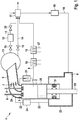
- Figure 1 shows a schematic drawing of a first embodiment of a two-stroke, cross-head internal combustion engine 1.
- the engine 1 comprises the parts of the engine of figure 3 .
- a separation device 7 is arranged in the outlet pipe 29.
- the separation device 7 comprises two valves which open and close the two channels of the outlet pipe 29.
- a first component exhaust line 8 is connected to the outlet pipe 29.
- the connected first component exhaust line 8 guides a part of the exhaust gas through the outlet 5 to a first SCR reactor 10.
- the first SCR reactor 10 reduces nitrogen oxides in the exhaust gas with a selective catalytic reduction.
- catalysts used in such SCR reactors are titanium dioxide, doted with oxides of base metals such as vanadium and tungsten. The catalyst can be extruded from a mixture of titanium dioxide, vanadium and tungsten.
- cordierites with a wash coat made of titanium dioxide, vanadium and tungsten may be used.
- a metallic base may be coated with the mentioned wash coat.
- metal zeolites such as copper or iron zeolites could be used as catalyst.
- the reduction of nitrogen oxides is based on a reaction of the nitrogen oxides with ammonia.
- Ammonia is generated by injecting urea with a urea injector 21 upstream of the first SCR reactor 10. Only a part of the exhaust gas of the cylinder 2 is guided through the first component exhaust line 8.
- the exhaust gas guided through line 8 may have a temperature which is too low for the selective catalytic reaction. At low temperatures (such as below 290°C at 1.5 bar and 0.1% sulfur) sulfuric acid is neutralized by ammonia and forms sticky product ammonia bisulfate (ABS). ABS may deposit on the catalyst material of the SCR reactor.
- the line 8 may additionally comprise a heating element 16, which is disposed upstream of the first SCR reactor and may be disposed downstream of the urea injector 21.
- scavenge air is used during the exhaust phase to discharge a combustion gas from the combustion chamber 3.
- the exhaust gas comprises scavenge air as well as combustion gas.
- the combustion gas has a higher temperature than the scavenge air due to the combustion. Further, a concentration of nitrogen oxides is higher in the combustion gas than in the scavenge air.
- the temperature of the combustion gas is reduced. At low loads, this temperature is particularly low, because a fuel injection is small, an amount of combustion gas is low and an SCR reactor cannot operate properly.
- a first method of separating is closing a first valve of separation device 7 for the first component exhaust line 8 and closing a second valve of separation device 7 for the second component exhaust line 9.
- the exhaust gas is entirely guided through the first component exhaust line 8.
- both valves, for example butterfly valves, of separation device 7 are open and a majority of the exhaust gas is guided through the second component exhaust line 9.
- the engine shown in figure 1 comprises two outlet valves 6 for the combustion chamber 3. Even though two outlet valves are shown, preferably one or four valves are used.
- the outlet valves 6 are used to guide the exhaust gas. First, while combustion gas is expelled, the outlet valve for the first component exhaust line 8 is open while the outlet valve for the second component exhaust line 9 is closed. In this configuration, the exhaust gas is guided through the first component exhaust line 8. This may be supported by closing both butterfly valves of separation device 7. As soon as the scavenge air arrives at the outlet 5, the outlet valve 6 for the first component exhaust line 8 is closed and the outlet valve of the second component exhaust line 9 is opened.
- the separated part is guided through the first component exhaust line 8, which allows a reliable reduction of nitrogen oxides in the first SCR reactor 10.
- a small SCR since only a part of the exhaust gas is guided through line 8, a small SCR may be used.
- An SCR reactor 10 with a maximum capacity of 40% of a full load outflow rate is sufficient, which saves space.
- the SCR reactor 10 may comprise a reactor heater 27 to adjust the temperature in the reactor further.
- the second component exhaust line 9 leads to the exhaust gas receiver 11. From the exhaust gas receiver 11, the exhaust gas is let through an SCR pipe 13 or a bypass pipe 14.
- the SCR pipe 13 and the bypass pipe 14 each comprise valves 15. The valves 15 can be opened and closed independently such that the bypass pipe 14 and/or the SCR pipe 13 are used.
- the SCR pipe 13 comprises a second SCR reactor 12.
- the second SCR reactor 12 is adapted for higher throughputs than the first SCR reactor 10.
- the second SCR reactor 12 has a maximum capacity of at least 60% of the full load outflow rate of the cylinders 2.
- the second SCR reactor 12 and the first SCR reactor 10 may have a combined total capacity of at least 100% of the full load outflow rate of the at least two cylinders.
- the bypass pipe may not comprise an SCR.
- the SCR pipe 13 comprises a second valve 20 downstream of the SCR reactor 12.
- the valve 20 prevents a backflow into the SCR pipe 13.
- the first line 8 and the second line 9 lead to a turbocharger 17 and to a funnel 30 (see figure 2 ) thereafter.
- the turbocharger 17 draws fresh air with the energy stored in the exhaust gas.
- the fresh air drawn by the turbocharger 17 is guided through a cooler system 19 and a fresh air feeder 18 to the inlet 4.
- the fresh air is guided through a scavenge air receiver 23 and through flushing holes 31 into the cylinder 2.
- An EGR pipe 22 is connected to the outlet 5 of the cylinder 2.
- the EGR pipe 22 leads exhaust gas to the EGR cleaner 24 and after the EGR cleaner 24 into the combustion chamber 3.
- the EGR cleaner 24 may comprise a scrubber, a cooler and a water mist catcher.
- the engine 1 as shown in figure 1 allows four different operational modes: A first operational mode is particularly suited for low loads and allows a fulfillment of tier III requirements.
- the valves 15 and the separation device 7 are set such that the first component exhaust line 8 and the bypass pipe 14 are open.
- the SCR pipe 13 is closed.
- a first part of the exhaust gas which comprises combustion gas is guided through the first SCR reactor 10, where nitrogen oxides are reduced.
- the rest of the exhaust gas, which mainly comprises scavenge air is guided through the bypass pipe 14.
- first SCR reactor 10 is not working and valve 15 of SCR bypass pipe 14 is closed.
- SCR reactor 10 can also be bypassed by a separated bypass line (not shown).
- the exhaust gas is guided through the second exhaust line 9 only and no exhaust gas is guided through the first exhaust line 8.
- the exhaust gas is only guided through the SCR pipe 13 and the second SCR reactor 12.
- the second operational mode corresponds to the SCR reactors in engine as known in the prior art.
- a third operational mode is particularly suited for high loads when a high nitrogen oxide reduction is desired (tier III).
- the first and second component exhaust lines 8, 9 are both open.
- the bypass pipe 14 is closed and the SCR pipe 13 is open.
- the first and second SCR reactor 10, 12 are run in parallel. At high loads, the scavenge air is sufficiently hot such that a reliable nitrogen oxide reduction becomes possible in the second SCR reactor 12.
- the first small SCR reactor 10 is particularly efficient in this operational mode, since the heater 16 may be switched off, because the combustion gas of the exhaust gas is sufficiently hot for the nitrogen oxide reaction without additional heating. Further, the first small SCR reactor 10 allows a higher reduction of nitrogen oxides because the nitrogen oxides have a higher concentration in the parts directed to the first SCR reactor 10.
- the relative NOx reduction preferably is above the required Tier III level to ensure meeting Tier III criteria after mixing with the non-reduced part of the exhaust.
- a fourth operational mode the exhaust gas is guided through the bypass pipe 14 only and the first component exhaust line 8 as well as the SCR pipe 13 are closed. In this operational mode, the SCRs 10 and 12 are switched off.
- the fourth operational mode is particularly fuel efficient.
- Figure 2 shows a second embodiment of an internal combustion engine 1.
- the second embodiment of the engine 1 is similar to the first embodiment.
- the reference signs refer to similar features.
- the SCR pipe 13 with the second SCR reactor 12 and the bypass pipe 14 are arranged downstream of the turbocharger 17.
- Engine 1 comprises cylinders 2. At the outlet of the cylinders 2, and exhaust gas from the cylinders 2 is separated into a first and a second stream. The first stream is guided through a first component exhaust line 8 and the second stream is guided through a second component exhaust line 9.
- the second component exhaust line 9 comprises the exhaust gas receiver 11.
- the first component exhaust line 8 is composed as shown with reference to figure 1 , comprises the first SCR reactor 10 and is parallel to the exhaust gas receiver 11. After the first SCR reactor 10 and before the second SCR reactor 12 and the bypass pipe 14, the first component exhaust line 8 merges into the second line 9 and the entire exhaust gas of all cylinders 2 is guided through the turbocharger 17.
- the second component exhaust line 9 allows the exhaust gas to be directed into the second SCR reactor 12 through the SCR pipe 13 or through the bypass pipe 14. Thereafter, the exhaust gas may be released through a funnel 30.
- the second SCR reactor 12 and the bypass pipe 14 may be arranged upstream of the turbocharger 17.
Landscapes
- Engineering & Computer Science (AREA)
- Chemical & Material Sciences (AREA)
- Combustion & Propulsion (AREA)
- Mechanical Engineering (AREA)
- General Engineering & Computer Science (AREA)
- Chemical Kinetics & Catalysis (AREA)
- Health & Medical Sciences (AREA)
- Toxicology (AREA)
- Ocean & Marine Engineering (AREA)
- Exhaust Gas After Treatment (AREA)
- Output Control And Ontrol Of Special Type Engine (AREA)
Priority Applications (6)
| Application Number | Priority Date | Filing Date | Title |
|---|---|---|---|
| EP18173078.9A EP3569834A1 (fr) | 2018-05-18 | 2018-05-18 | Moteur à combustion interne et procédé pour réduire les émissions d'oxyde d'azote |
| KR1020190054894A KR102697296B1 (ko) | 2018-05-18 | 2019-05-10 | 질소 산화물 배출을 저감시키기 위한 내연 엔진 및 방법 |
| CN201910397937.XA CN110500165B (zh) | 2018-05-18 | 2019-05-14 | 内部燃烧发动机和用于减少氧化氮排放的方法 |
| DK19175055.3T DK3569835T3 (da) | 2018-05-18 | 2019-05-17 | Forbrændingsmotor og fremgangsmåde til reduktion af nitrogenoxidemissioner |
| JP2019093964A JP7418969B2 (ja) | 2018-05-18 | 2019-05-17 | 内燃エンジン、及び窒素酸化物排出物を還元するための方法 |
| EP19175055.3A EP3569835B1 (fr) | 2018-05-18 | 2019-05-17 | Moteur à combustion interne et procédé pour réduire les émissions d'oxyde d'azote |
Applications Claiming Priority (1)
| Application Number | Priority Date | Filing Date | Title |
|---|---|---|---|
| EP18173078.9A EP3569834A1 (fr) | 2018-05-18 | 2018-05-18 | Moteur à combustion interne et procédé pour réduire les émissions d'oxyde d'azote |
Publications (1)
| Publication Number | Publication Date |
|---|---|
| EP3569834A1 true EP3569834A1 (fr) | 2019-11-20 |
Family
ID=62217782
Family Applications (2)
| Application Number | Title | Priority Date | Filing Date |
|---|---|---|---|
| EP18173078.9A Withdrawn EP3569834A1 (fr) | 2018-05-18 | 2018-05-18 | Moteur à combustion interne et procédé pour réduire les émissions d'oxyde d'azote |
| EP19175055.3A Active EP3569835B1 (fr) | 2018-05-18 | 2019-05-17 | Moteur à combustion interne et procédé pour réduire les émissions d'oxyde d'azote |
Family Applications After (1)
| Application Number | Title | Priority Date | Filing Date |
|---|---|---|---|
| EP19175055.3A Active EP3569835B1 (fr) | 2018-05-18 | 2019-05-17 | Moteur à combustion interne et procédé pour réduire les émissions d'oxyde d'azote |
Country Status (5)
| Country | Link |
|---|---|
| EP (2) | EP3569834A1 (fr) |
| JP (1) | JP7418969B2 (fr) |
| KR (1) | KR102697296B1 (fr) |
| CN (1) | CN110500165B (fr) |
| DK (1) | DK3569835T3 (fr) |
Families Citing this family (2)
| Publication number | Priority date | Publication date | Assignee | Title |
|---|---|---|---|---|
| DK180561B1 (en) * | 2020-03-06 | 2021-06-24 | Man Energy Solutions Filial Af Man Energy Solutions Se Tyskland | An internal combustion engine configured for determining specific emissions and a method for determining specific emissions of an internal combustion engine |
| DE102020214063A1 (de) * | 2020-03-13 | 2021-09-16 | centrotherm international AG | Verfahren und system zur selektiven abgasbehandlung |
Citations (9)
| Publication number | Priority date | Publication date | Assignee | Title |
|---|---|---|---|---|
| WO2002075124A1 (fr) * | 2001-03-16 | 2002-09-26 | Robert Bosch Gmbh | Element de commande pour la distribution simultanee de flux gazeux |
| WO2007010664A1 (fr) * | 2005-07-15 | 2007-01-25 | Nissan Diesel Motor Co., Ltd. | Appareil d’épuration des gaz d’échappement |
| EP2055909A1 (fr) * | 2007-10-31 | 2009-05-06 | Robert Bosch GmbH | Procédé de fonctionnement pauvre en émissions de matières toxiques d'un moteur à combustion et moteur à combustion correspondant |
| EP2151569A1 (fr) | 2008-08-06 | 2010-02-10 | Wärtsilä Switzerland Ltd. | Dispositif d'extraction d'un flux partiel de gaz d'échappement et moteur à combustion interne en étant équipé |
| DE102008058612A1 (de) | 2008-11-22 | 2010-05-27 | Man Diesel Filial Af Man Se- Tyskland | Verbrennungsmotor |
| US20100199643A1 (en) * | 2009-02-12 | 2010-08-12 | Yasser Mohamed Sayed Yacoub | Exhaust gas purification system |
| US20120023907A1 (en) * | 2011-07-15 | 2012-02-02 | Ford Global Technologies, Llc | System and method for processing nh3 slippage of a selective catalyst reduction system |
| WO2012051273A1 (fr) * | 2010-10-13 | 2012-04-19 | Cummins Intellectual Property, Inc. | Système et procédé de post-traitement d'un échappement à plusieurs branches |
| DK201570704A1 (en) | 2015-11-02 | 2017-05-15 | Man Diesel & Turbo Filial Af Man Diesel & Turbo Se Tyskland | A two-stroke internal combustion engine with a SCR reactor located downstream of the exhaust gas receiver |
Family Cites Families (6)
| Publication number | Priority date | Publication date | Assignee | Title |
|---|---|---|---|---|
| FR2608677B1 (fr) * | 1986-12-19 | 1989-04-28 | Inst Francais Du Petrole | Dispositif et procede d'amorcage rapide d'un catalyseur d'oxydation pour un moteur deux temps |
| US4969329A (en) * | 1989-05-05 | 1990-11-13 | General Motors Corporation | Two cycle engine with exhaust emission control |
| US6843054B2 (en) * | 2003-01-16 | 2005-01-18 | Arvin Technologies, Inc. | Method and apparatus for removing NOx and soot from engine exhaust gas |
| US7735314B2 (en) * | 2007-05-25 | 2010-06-15 | Southwest Research Institute | Exhaust after-treatment system with flow control for optimum temperature conditions |
| WO2012151273A1 (fr) | 2011-05-02 | 2012-11-08 | Get Arm Strength, Llc | Aide d'entraînement de la force |
| US9080487B2 (en) * | 2012-11-30 | 2015-07-14 | Tenneco Automotive Operating Company, Inc. | Reductant injection control system |
-
2018
- 2018-05-18 EP EP18173078.9A patent/EP3569834A1/fr not_active Withdrawn
-
2019
- 2019-05-10 KR KR1020190054894A patent/KR102697296B1/ko active Active
- 2019-05-14 CN CN201910397937.XA patent/CN110500165B/zh active Active
- 2019-05-17 EP EP19175055.3A patent/EP3569835B1/fr active Active
- 2019-05-17 JP JP2019093964A patent/JP7418969B2/ja active Active
- 2019-05-17 DK DK19175055.3T patent/DK3569835T3/da active
Patent Citations (9)
| Publication number | Priority date | Publication date | Assignee | Title |
|---|---|---|---|---|
| WO2002075124A1 (fr) * | 2001-03-16 | 2002-09-26 | Robert Bosch Gmbh | Element de commande pour la distribution simultanee de flux gazeux |
| WO2007010664A1 (fr) * | 2005-07-15 | 2007-01-25 | Nissan Diesel Motor Co., Ltd. | Appareil d’épuration des gaz d’échappement |
| EP2055909A1 (fr) * | 2007-10-31 | 2009-05-06 | Robert Bosch GmbH | Procédé de fonctionnement pauvre en émissions de matières toxiques d'un moteur à combustion et moteur à combustion correspondant |
| EP2151569A1 (fr) | 2008-08-06 | 2010-02-10 | Wärtsilä Switzerland Ltd. | Dispositif d'extraction d'un flux partiel de gaz d'échappement et moteur à combustion interne en étant équipé |
| DE102008058612A1 (de) | 2008-11-22 | 2010-05-27 | Man Diesel Filial Af Man Se- Tyskland | Verbrennungsmotor |
| US20100199643A1 (en) * | 2009-02-12 | 2010-08-12 | Yasser Mohamed Sayed Yacoub | Exhaust gas purification system |
| WO2012051273A1 (fr) * | 2010-10-13 | 2012-04-19 | Cummins Intellectual Property, Inc. | Système et procédé de post-traitement d'un échappement à plusieurs branches |
| US20120023907A1 (en) * | 2011-07-15 | 2012-02-02 | Ford Global Technologies, Llc | System and method for processing nh3 slippage of a selective catalyst reduction system |
| DK201570704A1 (en) | 2015-11-02 | 2017-05-15 | Man Diesel & Turbo Filial Af Man Diesel & Turbo Se Tyskland | A two-stroke internal combustion engine with a SCR reactor located downstream of the exhaust gas receiver |
Also Published As
| Publication number | Publication date |
|---|---|
| JP7418969B2 (ja) | 2024-01-22 |
| JP2019199875A (ja) | 2019-11-21 |
| KR20190132221A (ko) | 2019-11-27 |
| KR102697296B1 (ko) | 2024-08-20 |
| CN110500165B (zh) | 2022-12-27 |
| EP3569835B1 (fr) | 2024-03-20 |
| DK3569835T3 (da) | 2024-04-15 |
| EP3569835A1 (fr) | 2019-11-20 |
| CN110500165A (zh) | 2019-11-26 |
Similar Documents
| Publication | Publication Date | Title |
|---|---|---|
| EP2525057B1 (fr) | Système de dénitration des gaz d'échappement, bateau équipé de ce système et procédé pour commander un système de dénitration des gaz d'échappement | |
| US8418680B2 (en) | Gas guide system for a combustion engine, a combustion engine and a method for operating the engine | |
| KR101671271B1 (ko) | 배기가스 정화기능을 갖는 대형 터보차지 2-행정 디젤 엔진 | |
| US8950176B2 (en) | System for reducing engine emissions and backpressure using parallel emission reduction equipment | |
| EP3519685B1 (fr) | Système d'échappement à multiples rangées comprenant un système d'apport d'agent réducteur agencé en amont d'une turbine | |
| US20100199643A1 (en) | Exhaust gas purification system | |
| DE102016202778B4 (de) | Verfahren und Vorrichtung zur Abgasnachbehandlung eines Verbrennungsmotors | |
| FI124936B (fi) | Järjestely mäntäpolttomoottorin pakokaasujen vähentämiseksi, mäntäpolttomoottori ja menetelmä mäntäpolttomoottorin pakokaasujen käsittelemiseksi | |
| CN107035518B (zh) | 具有位于排气接收器的下游的scr反应器的二冲程内燃机 | |
| EP2344748B1 (fr) | Système de moteur à combustion interne et ensemble filtre à particules pour un tel système de moteur à combustion interne | |
| WO2018113930A1 (fr) | Procédé de commande d'un moteur à combustion interne | |
| CN107269351B (zh) | 带有排气后处理系统的内燃机 | |
| EP3569835B1 (fr) | Moteur à combustion interne et procédé pour réduire les émissions d'oxyde d'azote | |
| US20130000297A1 (en) | Emissions reduction system | |
| EP3754164B1 (fr) | Moteur à combustion interne et procédé de réduction d'émissions de matières particulaires | |
| CN113202604A (zh) | 具有在涡轮增压器上游的排气后处理装置的发动机组件 | |
| EP3527794A2 (fr) | Système de traitement de gas d'échappement pour un moteur à combustion interne et moteur à combustion interne avec un système de traitement de gas d'échappement |
Legal Events
| Date | Code | Title | Description |
|---|---|---|---|
| PUAI | Public reference made under article 153(3) epc to a published international application that has entered the european phase |
Free format text: ORIGINAL CODE: 0009012 |
|
| AK | Designated contracting states |
Kind code of ref document: A1 Designated state(s): AL AT BE BG CH CY CZ DE DK EE ES FI FR GB GR HR HU IE IS IT LI LT LU LV MC MK MT NL NO PL PT RO RS SE SI SK SM TR |
|
| AX | Request for extension of the european patent |
Extension state: BA ME |
|
| STAA | Information on the status of an ep patent application or granted ep patent |
Free format text: STATUS: THE APPLICATION IS DEEMED TO BE WITHDRAWN |
|
| 18D | Application deemed to be withdrawn |
Effective date: 20200603 |