EP3569874A1 - Moyens de connexion pour une étagère dans un carrousel de stockage - Google Patents
Moyens de connexion pour une étagère dans un carrousel de stockage Download PDFInfo
- Publication number
- EP3569874A1 EP3569874A1 EP18172225.7A EP18172225A EP3569874A1 EP 3569874 A1 EP3569874 A1 EP 3569874A1 EP 18172225 A EP18172225 A EP 18172225A EP 3569874 A1 EP3569874 A1 EP 3569874A1
- Authority
- EP
- European Patent Office
- Prior art keywords
- shelf
- cabinet
- attachment means
- attachment
- pivotable part
- Prior art date
- Legal status (The legal status is an assumption and is not a legal conclusion. Google has not performed a legal analysis and makes no representation as to the accuracy of the status listed.)
- Granted
Links
Images


Classifications
-
- A—HUMAN NECESSITIES
- A47—FURNITURE; DOMESTIC ARTICLES OR APPLIANCES; COFFEE MILLS; SPICE MILLS; SUCTION CLEANERS IN GENERAL
- A47B—TABLES; DESKS; OFFICE FURNITURE; CABINETS; DRAWERS; GENERAL DETAILS OF FURNITURE
- A47B81/00—Cabinets or racks specially adapted for other particular purposes, e.g. for storing guns or skis
- A47B81/002—Corner cabinets; Cabinets designed for being placed in a corner or a niche
-
- A—HUMAN NECESSITIES
- A47—FURNITURE; DOMESTIC ARTICLES OR APPLIANCES; COFFEE MILLS; SPICE MILLS; SUCTION CLEANERS IN GENERAL
- A47B—TABLES; DESKS; OFFICE FURNITURE; CABINETS; DRAWERS; GENERAL DETAILS OF FURNITURE
- A47B96/00—Details of cabinets, racks or shelf units not covered by a single one of groups A47B43/00 - A47B95/00; General details of furniture
- A47B96/02—Shelves
- A47B96/024—Shelves characterised by support bracket location means, e.g. fixing means between support bracket and shelf
-
- F—MECHANICAL ENGINEERING; LIGHTING; HEATING; WEAPONS; BLASTING
- F16—ENGINEERING ELEMENTS AND UNITS; GENERAL MEASURES FOR PRODUCING AND MAINTAINING EFFECTIVE FUNCTIONING OF MACHINES OR INSTALLATIONS; THERMAL INSULATION IN GENERAL
- F16B—DEVICES FOR FASTENING OR SECURING CONSTRUCTIONAL ELEMENTS OR MACHINE PARTS TOGETHER, e.g. NAILS, BOLTS, CIRCLIPS, CLAMPS, CLIPS OR WEDGES; JOINTS OR JOINTING
- F16B12/00—Jointing of furniture or the like, e.g. hidden from exterior
- F16B12/10—Jointing of furniture or the like, e.g. hidden from exterior using pegs, bolts, tenons, clamps, clips, or the like
- F16B12/12—Jointing of furniture or the like, e.g. hidden from exterior using pegs, bolts, tenons, clamps, clips, or the like for non-metal furniture parts, e.g. made of wood, of plastics
- F16B12/20—Jointing of furniture or the like, e.g. hidden from exterior using pegs, bolts, tenons, clamps, clips, or the like for non-metal furniture parts, e.g. made of wood, of plastics using clamps, clips, wedges, sliding bolts, or the like
- F16B12/2009—Jointing of furniture or the like, e.g. hidden from exterior using pegs, bolts, tenons, clamps, clips, or the like for non-metal furniture parts, e.g. made of wood, of plastics using clamps, clips, wedges, sliding bolts, or the like actuated by rotary motion
-
- F—MECHANICAL ENGINEERING; LIGHTING; HEATING; WEAPONS; BLASTING
- F16—ENGINEERING ELEMENTS AND UNITS; GENERAL MEASURES FOR PRODUCING AND MAINTAINING EFFECTIVE FUNCTIONING OF MACHINES OR INSTALLATIONS; THERMAL INSULATION IN GENERAL
- F16M—FRAMES, CASINGS OR BEDS OF ENGINES, MACHINES OR APPARATUS, NOT SPECIFIC TO ENGINES, MACHINES OR APPARATUS PROVIDED FOR ELSEWHERE; STANDS; SUPPORTS
- F16M11/00—Stands or trestles as supports for apparatus or articles placed thereon ; Stands for scientific apparatus such as gravitational force meters
- F16M11/02—Heads
- F16M11/04—Means for attachment of apparatus; Means allowing adjustment of the apparatus relatively to the stand
- F16M11/041—Allowing quick release of the apparatus
-
- F—MECHANICAL ENGINEERING; LIGHTING; HEATING; WEAPONS; BLASTING
- F16—ENGINEERING ELEMENTS AND UNITS; GENERAL MEASURES FOR PRODUCING AND MAINTAINING EFFECTIVE FUNCTIONING OF MACHINES OR INSTALLATIONS; THERMAL INSULATION IN GENERAL
- F16M—FRAMES, CASINGS OR BEDS OF ENGINES, MACHINES OR APPARATUS, NOT SPECIFIC TO ENGINES, MACHINES OR APPARATUS PROVIDED FOR ELSEWHERE; STANDS; SUPPORTS
- F16M11/00—Stands or trestles as supports for apparatus or articles placed thereon ; Stands for scientific apparatus such as gravitational force meters
- F16M11/02—Heads
- F16M11/04—Means for attachment of apparatus; Means allowing adjustment of the apparatus relatively to the stand
- F16M11/06—Means for attachment of apparatus; Means allowing adjustment of the apparatus relatively to the stand allowing pivoting
- F16M11/08—Means for attachment of apparatus; Means allowing adjustment of the apparatus relatively to the stand allowing pivoting around a vertical axis, e.g. panoramic heads
-
- F—MECHANICAL ENGINEERING; LIGHTING; HEATING; WEAPONS; BLASTING
- F16—ENGINEERING ELEMENTS AND UNITS; GENERAL MEASURES FOR PRODUCING AND MAINTAINING EFFECTIVE FUNCTIONING OF MACHINES OR INSTALLATIONS; THERMAL INSULATION IN GENERAL
- F16M—FRAMES, CASINGS OR BEDS OF ENGINES, MACHINES OR APPARATUS, NOT SPECIFIC TO ENGINES, MACHINES OR APPARATUS PROVIDED FOR ELSEWHERE; STANDS; SUPPORTS
- F16M11/00—Stands or trestles as supports for apparatus or articles placed thereon ; Stands for scientific apparatus such as gravitational force meters
- F16M11/20—Undercarriages with or without wheels
- F16M11/22—Undercarriages with or without wheels with approximately constant height, e.g. with constant length of column or of legs
-
- A—HUMAN NECESSITIES
- A47—FURNITURE; DOMESTIC ARTICLES OR APPLIANCES; COFFEE MILLS; SPICE MILLS; SUCTION CLEANERS IN GENERAL
- A47B—TABLES; DESKS; OFFICE FURNITURE; CABINETS; DRAWERS; GENERAL DETAILS OF FURNITURE
- A47B2230/00—Furniture jointing; Furniture with such jointing
- A47B2230/07—Releasable locking means or connectors for fastening together parts of furniture
-
- A—HUMAN NECESSITIES
- A47—FURNITURE; DOMESTIC ARTICLES OR APPLIANCES; COFFEE MILLS; SPICE MILLS; SUCTION CLEANERS IN GENERAL
- A47B—TABLES; DESKS; OFFICE FURNITURE; CABINETS; DRAWERS; GENERAL DETAILS OF FURNITURE
- A47B57/00—Cabinets, racks or shelf units, characterised by features for adjusting shelves or partitions
- A47B57/30—Cabinets, racks or shelf units, characterised by features for adjusting shelves or partitions with means for adjusting the height of detachable shelf supports
- A47B57/54—Cabinets, racks or shelf units, characterised by features for adjusting shelves or partitions with means for adjusting the height of detachable shelf supports consisting of clamping means, e.g. with sliding bolts or sliding wedges
-
- F—MECHANICAL ENGINEERING; LIGHTING; HEATING; WEAPONS; BLASTING
- F16—ENGINEERING ELEMENTS AND UNITS; GENERAL MEASURES FOR PRODUCING AND MAINTAINING EFFECTIVE FUNCTIONING OF MACHINES OR INSTALLATIONS; THERMAL INSULATION IN GENERAL
- F16M—FRAMES, CASINGS OR BEDS OF ENGINES, MACHINES OR APPARATUS, NOT SPECIFIC TO ENGINES, MACHINES OR APPARATUS PROVIDED FOR ELSEWHERE; STANDS; SUPPORTS
- F16M2200/00—Details of stands or supports
- F16M2200/02—Locking means
- F16M2200/025—Locking means for translational movement
- F16M2200/028—Locking means for translational movement by positive interaction, e.g. male-female connections
Definitions
- the invention discloses a storage carousel for storage of articles in a cabinet and connection means for connecting a shelf in a cabinet at the storage carousel. More particularly the disclosure relates to connecting means enabling a quick fixture of the shelf to a bottom or a guide arm of the storage carousel and also a quick release of the shelf.
- Cabinets typically comprise a shelf, or a plurality of shelves provided for the storage of articles.
- Previously known storage carousels often have circular and rotatable shelves around a central post. Some varieties are half-circular or three quarters of a circle, with the post positioned as for a full circle. Utilizing the space of the shelf to maximum is essential for all different shapes of shelves. For solutions with a central post, the available space on the storage shelf is not used efficiently, since the central post occupies space. Conversely, if the whole shelf is accessible, then the storing of articles becomes more optimal. Further, in prior art solutions, the installing of the shelves into the cabinet on the post is often complicated as well as setting the height between several shelves in the cabinet. In prior art solutions, uninstalling of the shelf, i.e. taking out a shelf from the cabinet for cleaning etc., is rather complicated. Known solutions are more or less mounted into the cabinet in a non-releasable manner.
- the invention discloses connecting means for an easy and quick connection of a shelf to a storage carousel, and a storage carousel comprising the quick connecting means.
- the invention further discloses a storage carousel solution which lacks a central post and further that the final setting of the height between the shelves when assembling the storage carousel is stepless and very quick and easy to manage. It is also easy to change height setting of a shelf after the assembly.
- connecting means for pivotable connection of a shelf to a cabinet comprises first attachment means arranged for attachment either to the shelf or the cabinet, and second attachment means arranged for attachment to the one of the shelf or the cabinet to which the first attachment means is not connected.
- the connecting means further comprising a pivotable part arranged at the first attachment means, which pivotable part is pivotable relative the first attachment means.
- the pivotable part comprises first engagement means
- the second attachments means comprises corresponding second engagement means
- the pivotable part is lockable relative to the second attachments means by engaging the first engagement means with the second engagement means.
- Such an arrangement provides an easy and quick connection of a shelf to a storage carousel in a cabinet. Since the first attachment means is attached to the cabinet (indirectly or directly) and the second attachment means is arranged on the shelf, or vice versa, it is very easy to install the shelf in the cabinet by inserting the same in the cabinet, placing the shelf with its attachment means on the corresponding attachment means in the cabinet and connect the engagement means to each other. By that the shelf is locked to the pivotable part of the first attachment means via the second attachment means, the shelf is pivotally and safely fitted in the cabinet in a very easy and quick manner compared to prior art solutions.
- the pivotable part is a disc and the first engagement means is at least one radially protruding tab arranged on a periphery of the disc.
- the disc comprises three or four protruding tabs, but one is enough for engaging the first and second engaging means such as the disc is locked to the second attachment means.
- the disc is pivotable relative to the first attachment means, preferably by means of a ball-bearing arranged between the first attachment means and the pivotable disc. Making the pivotable part as a disc with protruding tabs is a production efficient solution which enables an easy solution of the engagement function between the first and second attachment means.
- the pivotable part comprises an actuation arm, which is fixedly arranged to the pivotable part.
- the actuation arm is arranged for actuating the locking/unlocking of the pivotable part relative to the second attachments means by a pivoting movement of the actuation arm, wherein the pivotable part engages/disengages the first engagement means with the second engagement means.
- the actuation arm provides an easy management for pivoting the pivoting part and further, the pivotable part and the engaging means may be arranged in a protective housing or the like, to protect the user from the moving and locking parts of the connecting means.
- the actuation arm protrudes radially from the pivotable part.
- the radially protruding actuation arm does not need to protrude exactly radially but may be adapted with a suitable angle relative the radial direction from the pivoting center of the pivoting part.
- the actuation arm may also be fixedly attached to the pivoting part at a distance from the pivoting center of the pivoting part.
- the actuation arm is lockable when the pivotable part of the first attachment means is locked relative to the second attachments means. This means that the arm is secured when the shelf is locked to the pivotable part, i.e. when the shelf is mounted in the cabinet in the using mode of the storage carousel. By this, the shelf may not fall off from the fastened position, and the actuation arm is in this position out of way when rotating the shelf.
- the second attachment means has inner dimensions which substantially corresponds with outer dimensions of the disc, such as the disc fits inside the second attachment means.
- the second attachment means comprises at least one recess arranged to receive the at least one radially protruding tab of the disc, and the second engagement means is at least one locking groove, which is arranged in connection to the at least one recess. For locking the disc relative to the second attachment means is each protruding tab insertable into the respective locking groove from the respective recess.
- each locking groove have an opening towards the adjacent recess such as the protruding tab first may be inserted into the recess and then, by pivoting the pivotable part, the protruding tab enters the locking groove for engaging the first and the second engaging means (tab into the locking groove).
- the second attachment means has the form of a circular ring, and the pivoting part the form of a circular disc.
- a storage carousel for a cabinet comprises at least one shelf and at least one connecting means for pivotable connection of the shelf to the cabinet.
- the connecting means comprises first attachment means arranged for attachment either to the shelf or the cabinet, and second attachment means arranged for attachment to the one of the shelf or the cabinet to which the first attachment means is not connected.
- the storage carousel further comprises a pivotable part which is arranged at the first attachment means, and said pivotable part is pivotable relative the first attachment means.
- the pivotable part comprises first engagement means and the second attachments means comprises corresponding second engagement means, and the pivotable part is lockable relative to the second attachments means by engaging the first engagement means with the second engagement means, wherein the shelf in its locked position relative the pivotable part, is pivotable.
- the storage carousel solution it is very easy and quick to assemble a shelf in the cabinet because of the inventive connecting means. It is very easy to install the shelf since the first attachment means is attached to the cabinet (indirectly or directly) and the second attachment means is arranged on the shelf, or vice versa.
- the storage carousel By inserting the shelf in the cabinet, placing the shelf with its attachment means on the corresponding attachment means in the cabinet and connect the engagement means to each other, the storage carousel is fitted with the shelf in a simple and user-friendly way.
- the shelf is locked to the pivotable part of the first attachment means via the second attachment means, the storage carousel discloses a shelf which is pivotally and safely fitted in the cabinet in a very easy and quick manner compared to prior art solutions.
- the pivotable part of the first attachment means is a disc and the first engagement means is at least one radially protruding tab arranged on a periphery of the disc.
- the disc comprises three or four protruding tabs, but one is enough for engaging the first and second engaging means such as the disc is locked to the second attachment means.
- the disc is pivotable relative to the first attachment means, preferably by means of a ball-bearing arranged between the first attachment means and the pivotable disc. Making the pivotable part as a disc with protruding tabs is a production efficient solution which enables an easy solution of the engagement function between the first and second attachment means, wherein a shelf of the storage carousel is easy to connect and disconnect.
- the pivotable part comprises an actuation arm, which is fixedly arranged to the pivotable part.
- the actuation arm is arranged for actuating the locking/unlocking of the pivotable part relative to the second attachments means by a pivoting movement of the actuation arm, wherein the pivotable part engages/disengages the first engagement means with the second engagement means.
- the actuation arm provides an easy management for pivoting the pivoting part and further, the pivotable part and the engaging means may be arranged in a protective housing or the like, to protect the user from the moving and locking parts of the connecting means.
- the actuation arm protrudes radially from the pivotable part.
- the radially protruding actuation arm does not need to protrude exactly radially but may be adapted with a suitable angle relative the radial direction from the pivoting center of the pivoting part.
- the actuation arm may also be fixedly attached to the pivoting part at a distance from the pivoting center of the pivoting part.
- the actuation arm is lockable by a stop when the pivotable part of the first attachment means is locked relative to the second attachments means.
- the stop is preferably arranged on an opposite part of where the first attachment means is arranged. For example, if the first attachment means is arranged in fixed connection to the cabinet, that is for example on a supporting arm or at the bottom of the cabinet, the stop is positioned on the underside of the shelf.
- the stop is positioned on for example the bottom of the cabinet or at the supporting arm which carries the shelf.
- the second attachment means has inner dimensions which substantially corresponds with outer dimensions of the disc, such as the disc fits inside the second attachment means.
- the second attachment means comprises at least one recess arranged to receive the at least one radially protruding tab of the disc, and the second engagement means is at least one locking groove, which is arranged in connection to the at least one recess. For locking the disc relative to the second attachment means is each protruding tab insertable into the respective locking groove from the respective recess.
- Each locking groove has an opening towards the adjacent recess such as the protruding tab first may be inserted into the recess and then, by pivoting the pivotable part, the protruding tab enters the locking groove for engaging the first and the second engaging means.
- the second attachment means has the form of a circular ring, and the pivoting part the form of a circular disc.
- one first attachment means is arranged at an upper side of a bottom of the cabinet.
- one of several shelves may be fitted directly at the cabinet without any further vertical posts or the like, which is a cost-efficient solution compared to prior art.
- the connecting means and the assembly is exactly the same as described above.
- the storage carousel further comprises a guide rail, which is fixedly arranged to the cabinet, near a side wall of the cabinet.
- the storage carousel also comprises and a supporting arm and at least one first attachment means is arranged at a first end of the supporting arm.
- the supporting arm is slidingly arranged at the guide rail by that a second end of the supporting arm comprises a sleeve, which is slidably arranged at the guide rail, such as the sleeve can be displaced along the guide rail in a vertical direction in the cabinet.
- the sleeve is lockable to the guide rail by means of a friction lock.
- the friction lock is maneuvered with a locking handle between the unlocked (open) position and a locked (closed) position and provides the stepless locking of the sleeve to the guide rail, preferably by brake blocks or the like.
- an inventive connecting means for a storage carousel is provided as well as an inventive storage carousel comprising such a connecting means.
- the invention is a cost-efficient solution which is easy to assemble for an end user or a craftsman, which enables rapid assemble of shelves to a cabinet in storage carousel solutions.
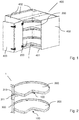
- Fig. 1 shows a perspective view of a cabinet 400 comprising a storage carousel 1 with two pivotable shelves 200.
- the cabinet 400 is a so-called corner-cabinet 400 and comprises a bottom 401, four sidewalls 402 and a door 403.
- On top of the cabinet 400 is normally a work top positioned (not visible).
- the two pivotable shelves 200 have a three-quarter circular shape and they are pivotably attached to the storage carousel 1, which will be explained below.
- the inventive storage carousel 1 lacks a central post, which means that a larger surface is available for storage.
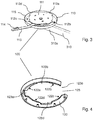
- Fig. 2 shows a perspective view of the storage carousel 1 where the lower of the two shelves 200 is to be mounted directly on the bottom 401 of the cabinet 400, by means of a connection means 100 according to the invention.
- the upper of the two shelves 200 is mounted at the end of a supporting arm 310, by means of the same type of connection means 100, attached to the supporting arm 310.
- the supporting arm 310 is slidingly arranged at a guiding rail 300 by means of a sleeve 311, which is fitted on the supporting arm 310, and which also is slidingly arranged at the guiding rail 300.
- the guiding rail 300 is arranged to be fixedly attached to an inside of one of the sidewalls 402 of the cabinet 400, outside the periphery of the shelf 200.
- the lower shelf 200 is fixed in the vertical direction, while the upper shelf 200 is adjustable in the vertical direction. It is also possible to fit a third shelf 200 to the guide rail if wanted, or several more shelves 200.
- Fig. 3 shows a perspective view of a first attachment means 110 of the connecting means 100 for connecting the shelf 200 to the cabinet 400, at the storage carousel 1 according to the invention.
- the first attachment means 110 is fixedly mounted to a first end 310a of the supporting arm 310, but if the first attachment means 110 is to be mounted directly at an upper side of the bottom 401 of the cabinet (as in Fig. 9a ), it is preferably screwed directly to the bottom 401.
- the first and the second attachment means 110, 120 may be arranged in the opposite way, such as instead the shelf 200 comprises the first attachment means 110 and the cabinet bottom 401 or the supporting arm 310 comprises the second attachment means 120.
- the first attachment means110 has the form of a circular plate with an outer rim 115 and carries a pivotable part 111 in the form of a circular disc 111.
- the circular disc 111 is pivotable relative to the first attachment means 110 by means of a ball-bearing (not visible).
- the pivotable disc 111 comprises first engagement means 112 in the form of four radially protruding tabs 112a, 112b, 112c, 112d arranged on a periphery of the disc 111.
- the pivotable disc 111 further comprises an actuation arm 113, which is fixedly arranged to the disc 111 such as it protrudes radially from the pivotable disc 111.
- the actuation arm 113 is arranged for actuating the locking/unlocking of the pivotable part 111 relative to the second attachments means 120 by pivoting the actuation arm 113, which will be explained further below.
- Fig. 4 shows a perspective view of a second attachment means 120 of the connecting means 100 for connecting the shelf 200 to the cabinet 400, at the storage carousel 1 according to the invention.
- the second attachment means 120 is designed as a circular ring with a gap section 125 and the second attachment means 120 is aimed to be fixedly attached on an underside 201 of the shelf 200, for example by screws (see Fig.5 ).
- the second attachment means 120 may be fitted on the bottom of the cabinet 400 or - if redesigned - on the supporting arm 310, if the first and the second attachment means 110, 120 are to be arranged in the opposite way.
- the first and the second attachment means 110, 120 such as the shelf 200 comprises the first attachment means 110 and the cabinet bottom 401 or the supporting arm 310 comprises the second attachment means 120.
- Inner dimensions of the second attachment means 120 (the ring), i.e. the inner diameter, substantially corresponds to outer dimensions/diameter of the disc 111, such as the disc 111 fits inside the ring/second attachment means 120.
- the second attachment means 120 further comprises four recesses 123a, 123b, 123c, 123d, which respective recess is arranged to receive one respective radially protruding tab 112a, 112b, 112c, 112d of the disc 111.
- the second attachment means 120 comprises second engagement means 122 in the form of locking grooves 122a, 122b, 122c, 122d, which are arranged in connection to a respective one of the recesses 123a, 123b, 123c, 123d.
- Each locking groove 122a, 122b, 122c, 122d has an opening towards the adjacent recess 123a, 123b, 123c, 123d such as one protruding tab 112a, 112b, 112c, 112d of the disc 111 is insertable first into a recess 123a, 123b, 123c, 123d and then is insertable into the corresponding locking groove 122a, 122b, 122c, 122d from the respective recess 123a, 123b, 123c, 123d, when the actuation arm 113 is pivoted, for locking the disc 111 into the second attachment means 120, see further Fig. 7a-b .
- Fig. 5 shows a perspective view of an underside 201 of the shelf 200, comprising the second attachment means 120 of the connecting means 100, which was presented in Fig. 4 .
- a rim 210 attached to outer periphery of the shelf 200 is also visible in the figure.
- On the underside 201 of the shelf 200 is a stop 205 arranged, which facilitates a locking of the actuation arm 113 connected to the pivotable disc 111. This will be explained below.
- Fig. 6 shows a perspective view of the first attachment means 110 presented in Fig. 3 , when fixedly mounted to the first end 310a of the supporting arm 310.
- the sleeve 311 fixedly attach.
- the sleeve 311 will be further presented below in connection to Fig. 8a-b .
- the first attachment means 110 and the second attachment means 120 are connected to form the complete connecting means 100 by fitting the second attachment means 120, i.e. the ring 120, outside the pivotable disc 111 and into the first attachment means 110, which will be further explained below.
- Fig. 7a-b shows perspective views of the connecting means 100 at different stages during mounting the shelf 200 to the cabinet by the connecting means 100.
- the views are oblique from above with the shelf 200 semi-transparent, to be able to see the connecting means 100.
- the shelf with its ring 120 positioned on the underside of the shelf 200 is placed on top of the first attachment means 110 such as the protruding tabs 112a, 112b, 112c, 112d of the disc 111 enters the respective recesses 123a, 123b, 123c, 123d, see Fig. 7a .
- the connecting means is in an unlocked stage.
- the outer rim 115 of the first attachment means 110 encloses the second attachment means/the ring 120 when the first and second attachment means 110, 120 are joined as the connecting means 100.
- the pivotable disc 111 is pivoted by the actuation arm 113, such as the protruding tabs 112a, 112b, 112c, 112d of the disc 111 enters respective locking grooves 122a, 122b, 122c, 122d of the ring 120 from the respective recess 123a, 123b, 123c, 123d, wherein the pivotable disc 11 now is locked to the ring 120, see Fig. 7b . In the figure, this is performed by a pivoting movement of the actuation arm 113 to the right.
- the actuation arm 113 is locked behind the stop 205, positioned on the underside 201 of the shelf 200, see also Fig. 9 and 10 .
- the actuation arm 113 may comprise a heel 114 arranged for locking against the stop 205.
- Fig. 8a-b shows perspective views of the second end 310b of the supporting arm 310 comprising the sleeve 311, where the latter is in an unlocked position (8a) and a locked position (8b).
- the sleeve 311 is slidingly arranged to the guiding rail 300 (not visible) as shown in Fig. 2 and 10c .
- the sleeve 311 comprises a friction lock 312 which is maneuvered with a locking handle 313 between the unlocked position of Fig. 8a and the locked position of Fig. 8b .
- the friction lock 312 provides a stepless locking of the sleeve 311 to the guide rail 300, by brake blocks or the like. This is a great advantage over prior art solutions, regarding easy handled mounting and setting of the height of the shelf 200 in the cabinet 400.
- Fig. 9a-b shows the assembly of the lower shelf 200 to the cabinet 400, where the first attachment means 110 of the connector 100 is positioned directly on an upper side of the bottom 401 of the cabinet 400.
- the cabinet 400 further comprises the rest of the storage carousel 1, such as guide rail 300, supporting arm 310 etc., but those parts are not visible in the figure.
- the second attachment means 120 is fixedly attached to the underside 201 of the shelf 200, and the shelf 200 is inserted into the cabinet 400 and positioned as explained on the first attachment means 110, such as the protruding tabs 112a, 112b, 112c, 112d of the disc 111 enters the recesses 123a, 123b, 123c, 123d.
- the shelf 200 is rotated to the right such as the shelf 200 is in position where the "open quarter" of the shelf 200 is in front of the opening of the cabinet 400, and in this position the actuation arm 113 is visible.
- the first engagement means 112 - the protruding tabs 112a, 112b, 112c, 112d of the disc 111 enters the locking grooves 122a, 122b, 122c, 122d of the ring 120, wherein the shelf 200 is locked to the pivoting disc 111.
- the actuation arm 113 is locked by placing said arm 113 behind the stop 205. Now the shelf 200 is secured and pivotable around its central axis in the cabinet 400, without risk of loosening from the first attachment means 110.
- Fig. 10a-c shows the assembly of the upper shelf 200 to the cabinet 400, where the first attachment means 110 of the connector 100 is positioned on the supporting arm 310, which in turn is attached to the guide rail 300 (not visible) via the sleeve 311 (not visible).
- the shelf 200 is inserted into the cabinet 400, positioned on the first attachment means 110, pivoted to the right, locked by the actuation arm 113 and then the actuation arm 113 is locked behind the stop 205.
- Several shelves 200 may be mounted in the same way on the same guide rail 300 if wanted.
- the supporting arm 310 is preferred to be positioned in a lowermost position, just above the lower shelf 200.
Landscapes
- Engineering & Computer Science (AREA)
- General Engineering & Computer Science (AREA)
- Mechanical Engineering (AREA)
- Automatic Disk Changers (AREA)
Priority Applications (1)
| Application Number | Priority Date | Filing Date | Title |
|---|---|---|---|
| EP18172225.7A EP3569874B1 (fr) | 2018-05-15 | 2018-05-15 | Carrousel de stockage |
Applications Claiming Priority (1)
| Application Number | Priority Date | Filing Date | Title |
|---|---|---|---|
| EP18172225.7A EP3569874B1 (fr) | 2018-05-15 | 2018-05-15 | Carrousel de stockage |
Publications (2)
| Publication Number | Publication Date |
|---|---|
| EP3569874A1 true EP3569874A1 (fr) | 2019-11-20 |
| EP3569874B1 EP3569874B1 (fr) | 2022-05-04 |
Family
ID=62167169
Family Applications (1)
| Application Number | Title | Priority Date | Filing Date |
|---|---|---|---|
| EP18172225.7A Active EP3569874B1 (fr) | 2018-05-15 | 2018-05-15 | Carrousel de stockage |
Country Status (1)
| Country | Link |
|---|---|
| EP (1) | EP3569874B1 (fr) |
Cited By (2)
| Publication number | Priority date | Publication date | Assignee | Title |
|---|---|---|---|---|
| CN111557556A (zh) * | 2020-05-19 | 2020-08-21 | 佛山市顺德区悍高五金制品有限公司 | 角柜配件及角柜 |
| US12478177B2 (en) * | 2021-09-10 | 2025-11-25 | Ninkaplast Gmbh | Pivot and pull-out fitting for a corner cabinet |
Citations (3)
| Publication number | Priority date | Publication date | Assignee | Title |
|---|---|---|---|---|
| AT10606U1 (de) * | 2008-02-21 | 2009-07-15 | Svoboda Entwicklungs Gmbh & Co | Vorrichtung zum verbinden von bauteilen |
| US20140262847A1 (en) * | 2013-03-15 | 2014-09-18 | The Joy Factory, Inc. | Case structures for portable electronic devices |
| DE202015101212U1 (de) * | 2015-03-10 | 2016-06-14 | Hetal-Werke Franz Hettich Gmbh & Co. Kg | Anbringvorrichtung für ein Tragelement an einer Tragsäule eines Möbels und Möbel |
-
2018
- 2018-05-15 EP EP18172225.7A patent/EP3569874B1/fr active Active
Patent Citations (3)
| Publication number | Priority date | Publication date | Assignee | Title |
|---|---|---|---|---|
| AT10606U1 (de) * | 2008-02-21 | 2009-07-15 | Svoboda Entwicklungs Gmbh & Co | Vorrichtung zum verbinden von bauteilen |
| US20140262847A1 (en) * | 2013-03-15 | 2014-09-18 | The Joy Factory, Inc. | Case structures for portable electronic devices |
| DE202015101212U1 (de) * | 2015-03-10 | 2016-06-14 | Hetal-Werke Franz Hettich Gmbh & Co. Kg | Anbringvorrichtung für ein Tragelement an einer Tragsäule eines Möbels und Möbel |
Cited By (2)
| Publication number | Priority date | Publication date | Assignee | Title |
|---|---|---|---|---|
| CN111557556A (zh) * | 2020-05-19 | 2020-08-21 | 佛山市顺德区悍高五金制品有限公司 | 角柜配件及角柜 |
| US12478177B2 (en) * | 2021-09-10 | 2025-11-25 | Ninkaplast Gmbh | Pivot and pull-out fitting for a corner cabinet |
Also Published As
| Publication number | Publication date |
|---|---|
| EP3569874B1 (fr) | 2022-05-04 |
Similar Documents
| Publication | Publication Date | Title |
|---|---|---|
| JP7315716B2 (ja) | 家具駆動装置 | |
| CN110118465B (zh) | 具有用于门的特定高度调节装置的家用制冷器具 | |
| JP7309750B2 (ja) | 家具又は家電製品用の収納棚、家具及び家庭用器具 | |
| US11560915B2 (en) | Compact joining and leveling system for parts of furniture and furnishing items | |
| EP1847198B1 (fr) | Ensemble de coulissement de tiroir pour lave-vaisselle de type tiroir | |
| EP3569874A1 (fr) | Moyens de connexion pour une étagère dans un carrousel de stockage | |
| EP2972022B1 (fr) | Charnière réglable pour le montage d'une porte à une armoire | |
| US7651180B2 (en) | Device for adjusting the height position of a dishware basket which can be pulled out from the rinsing container of a dishwasher | |
| US8434199B1 (en) | Cooking device knob safety assembly | |
| EP2792977B1 (fr) | Ensemble d'étagère pour réfrigérateur et réfrigérateur | |
| US20120097147A1 (en) | Extension rack assembly for consumer appliance and consumer appliance incorporating same | |
| US12239226B2 (en) | Device for supporting and fixing shelves of furniture | |
| CN111051712B (zh) | 用于家具部件和家具用品的具最小负担的接合和调平系统 | |
| US11219313B2 (en) | Unified joining and levelling system for parts of furniture and furnishing items | |
| CN202810428U (zh) | 闩锁机构 | |
| WO2018174997A1 (fr) | Dispositif permettant un montage sur une surface et comportant un mécanisme de verrouillage | |
| US20210284215A1 (en) | Grill accessory cart | |
| WO2014053412A1 (fr) | Trépied permettant de soutenir un équipement vidéo/photographique | |
| US11160373B2 (en) | Joining and levelling system for parts of furniture and furnishing items with the shoulder on the floor | |
| CN110652104B (zh) | 多功能安装支架 | |
| US20040129186A1 (en) | Assembly fitting with bayonet coupling | |
| WO2022095832A1 (fr) | Ensemble tiroir destiné à un appareil électrique, et appareil de réfrigération | |
| EP2237704A1 (fr) | Système d'assemblage pour relier des éléments de meuble | |
| CN115568708B (zh) | 家具或家用电器及在其中安装抽屉元件的功能单元的方法 | |
| CN102740735A (zh) | 能联锁的拉出导向装置 |
Legal Events
| Date | Code | Title | Description |
|---|---|---|---|
| PUAI | Public reference made under article 153(3) epc to a published international application that has entered the european phase |
Free format text: ORIGINAL CODE: 0009012 |
|
| STAA | Information on the status of an ep patent application or granted ep patent |
Free format text: STATUS: THE APPLICATION HAS BEEN PUBLISHED |
|
| AK | Designated contracting states |
Kind code of ref document: A1 Designated state(s): AL AT BE BG CH CY CZ DE DK EE ES FI FR GB GR HR HU IE IS IT LI LT LU LV MC MK MT NL NO PL PT RO RS SE SI SK SM TR |
|
| AX | Request for extension of the european patent |
Extension state: BA ME |
|
| STAA | Information on the status of an ep patent application or granted ep patent |
Free format text: STATUS: REQUEST FOR EXAMINATION WAS MADE |
|
| 17P | Request for examination filed |
Effective date: 20200507 |
|
| RBV | Designated contracting states (corrected) |
Designated state(s): AL AT BE BG CH CY CZ DE DK EE ES FI FR GB GR HR HU IE IS IT LI LT LU LV MC MK MT NL NO PL PT RO RS SE SI SK SM TR |
|
| STAA | Information on the status of an ep patent application or granted ep patent |
Free format text: STATUS: EXAMINATION IS IN PROGRESS |
|
| 17Q | First examination report despatched |
Effective date: 20210226 |
|
| RIC1 | Information provided on ipc code assigned before grant |
Ipc: A47B 57/54 20060101ALN20211018BHEP Ipc: F16M 11/22 20060101ALI20211018BHEP Ipc: F16M 11/08 20060101ALI20211018BHEP Ipc: F16M 11/04 20060101ALI20211018BHEP Ipc: A47B 96/02 20060101ALI20211018BHEP Ipc: F16B 12/20 20060101AFI20211018BHEP |
|
| GRAP | Despatch of communication of intention to grant a patent |
Free format text: ORIGINAL CODE: EPIDOSNIGR1 |
|
| STAA | Information on the status of an ep patent application or granted ep patent |
Free format text: STATUS: GRANT OF PATENT IS INTENDED |
|
| RIC1 | Information provided on ipc code assigned before grant |
Ipc: A47B 57/54 20060101ALN20211108BHEP Ipc: F16M 11/22 20060101ALI20211108BHEP Ipc: F16M 11/08 20060101ALI20211108BHEP Ipc: F16M 11/04 20060101ALI20211108BHEP Ipc: A47B 96/02 20060101ALI20211108BHEP Ipc: F16B 12/20 20060101AFI20211108BHEP |
|
| INTG | Intention to grant announced |
Effective date: 20211201 |
|
| GRAS | Grant fee paid |
Free format text: ORIGINAL CODE: EPIDOSNIGR3 |
|
| GRAA | (expected) grant |
Free format text: ORIGINAL CODE: 0009210 |
|
| STAA | Information on the status of an ep patent application or granted ep patent |
Free format text: STATUS: THE PATENT HAS BEEN GRANTED |
|
| AK | Designated contracting states |
Kind code of ref document: B1 Designated state(s): AL AT BE BG CH CY CZ DE DK EE ES FI FR GB GR HR HU IE IS IT LI LT LU LV MC MK MT NL NO PL PT RO RS SE SI SK SM TR |
|
| REG | Reference to a national code |
Ref country code: GB Ref legal event code: FG4D |
|
| REG | Reference to a national code |
Ref country code: CH Ref legal event code: EP |
|
| REG | Reference to a national code |
Ref country code: AT Ref legal event code: REF Ref document number: 1489332 Country of ref document: AT Kind code of ref document: T Effective date: 20220515 |
|
| REG | Reference to a national code |
Ref country code: FI Ref legal event code: FGE |
|
| REG | Reference to a national code |
Ref country code: IE Ref legal event code: FG4D Ref country code: DE Ref legal event code: R096 Ref document number: 602018034789 Country of ref document: DE |
|
| REG | Reference to a national code |
Ref country code: SE Ref legal event code: TRGR |
|
| REG | Reference to a national code |
Ref country code: NO Ref legal event code: T2 Effective date: 20220504 |
|
| REG | Reference to a national code |
Ref country code: LT Ref legal event code: MG9D |
|
| REG | Reference to a national code |
Ref country code: NL Ref legal event code: MP Effective date: 20220504 |
|
| REG | Reference to a national code |
Ref country code: AT Ref legal event code: MK05 Ref document number: 1489332 Country of ref document: AT Kind code of ref document: T Effective date: 20220504 |
|
| PG25 | Lapsed in a contracting state [announced via postgrant information from national office to epo] |
Ref country code: PT Free format text: LAPSE BECAUSE OF FAILURE TO SUBMIT A TRANSLATION OF THE DESCRIPTION OR TO PAY THE FEE WITHIN THE PRESCRIBED TIME-LIMIT Effective date: 20220905 Ref country code: NL Free format text: LAPSE BECAUSE OF FAILURE TO SUBMIT A TRANSLATION OF THE DESCRIPTION OR TO PAY THE FEE WITHIN THE PRESCRIBED TIME-LIMIT Effective date: 20220504 Ref country code: LT Free format text: LAPSE BECAUSE OF FAILURE TO SUBMIT A TRANSLATION OF THE DESCRIPTION OR TO PAY THE FEE WITHIN THE PRESCRIBED TIME-LIMIT Effective date: 20220504 Ref country code: HR Free format text: LAPSE BECAUSE OF FAILURE TO SUBMIT A TRANSLATION OF THE DESCRIPTION OR TO PAY THE FEE WITHIN THE PRESCRIBED TIME-LIMIT Effective date: 20220504 Ref country code: GR Free format text: LAPSE BECAUSE OF FAILURE TO SUBMIT A TRANSLATION OF THE DESCRIPTION OR TO PAY THE FEE WITHIN THE PRESCRIBED TIME-LIMIT Effective date: 20220805 Ref country code: ES Free format text: LAPSE BECAUSE OF FAILURE TO SUBMIT A TRANSLATION OF THE DESCRIPTION OR TO PAY THE FEE WITHIN THE PRESCRIBED TIME-LIMIT Effective date: 20220504 Ref country code: BG Free format text: LAPSE BECAUSE OF FAILURE TO SUBMIT A TRANSLATION OF THE DESCRIPTION OR TO PAY THE FEE WITHIN THE PRESCRIBED TIME-LIMIT Effective date: 20220804 Ref country code: AT Free format text: LAPSE BECAUSE OF FAILURE TO SUBMIT A TRANSLATION OF THE DESCRIPTION OR TO PAY THE FEE WITHIN THE PRESCRIBED TIME-LIMIT Effective date: 20220504 |
|
| PG25 | Lapsed in a contracting state [announced via postgrant information from national office to epo] |
Ref country code: RS Free format text: LAPSE BECAUSE OF FAILURE TO SUBMIT A TRANSLATION OF THE DESCRIPTION OR TO PAY THE FEE WITHIN THE PRESCRIBED TIME-LIMIT Effective date: 20220504 Ref country code: PL Free format text: LAPSE BECAUSE OF FAILURE TO SUBMIT A TRANSLATION OF THE DESCRIPTION OR TO PAY THE FEE WITHIN THE PRESCRIBED TIME-LIMIT Effective date: 20220504 Ref country code: LV Free format text: LAPSE BECAUSE OF FAILURE TO SUBMIT A TRANSLATION OF THE DESCRIPTION OR TO PAY THE FEE WITHIN THE PRESCRIBED TIME-LIMIT Effective date: 20220504 Ref country code: IS Free format text: LAPSE BECAUSE OF FAILURE TO SUBMIT A TRANSLATION OF THE DESCRIPTION OR TO PAY THE FEE WITHIN THE PRESCRIBED TIME-LIMIT Effective date: 20220904 |
|
| REG | Reference to a national code |
Ref country code: CH Ref legal event code: PL |
|
| REG | Reference to a national code |
Ref country code: BE Ref legal event code: MM Effective date: 20220531 |
|
| PG25 | Lapsed in a contracting state [announced via postgrant information from national office to epo] |
Ref country code: SM Free format text: LAPSE BECAUSE OF FAILURE TO SUBMIT A TRANSLATION OF THE DESCRIPTION OR TO PAY THE FEE WITHIN THE PRESCRIBED TIME-LIMIT Effective date: 20220504 Ref country code: SK Free format text: LAPSE BECAUSE OF FAILURE TO SUBMIT A TRANSLATION OF THE DESCRIPTION OR TO PAY THE FEE WITHIN THE PRESCRIBED TIME-LIMIT Effective date: 20220504 Ref country code: RO Free format text: LAPSE BECAUSE OF FAILURE TO SUBMIT A TRANSLATION OF THE DESCRIPTION OR TO PAY THE FEE WITHIN THE PRESCRIBED TIME-LIMIT Effective date: 20220504 Ref country code: LU Free format text: LAPSE BECAUSE OF NON-PAYMENT OF DUE FEES Effective date: 20220515 Ref country code: LI Free format text: LAPSE BECAUSE OF NON-PAYMENT OF DUE FEES Effective date: 20220531 Ref country code: EE Free format text: LAPSE BECAUSE OF FAILURE TO SUBMIT A TRANSLATION OF THE DESCRIPTION OR TO PAY THE FEE WITHIN THE PRESCRIBED TIME-LIMIT Effective date: 20220504 Ref country code: DK Free format text: LAPSE BECAUSE OF FAILURE TO SUBMIT A TRANSLATION OF THE DESCRIPTION OR TO PAY THE FEE WITHIN THE PRESCRIBED TIME-LIMIT Effective date: 20220504 Ref country code: CZ Free format text: LAPSE BECAUSE OF FAILURE TO SUBMIT A TRANSLATION OF THE DESCRIPTION OR TO PAY THE FEE WITHIN THE PRESCRIBED TIME-LIMIT Effective date: 20220504 Ref country code: CH Free format text: LAPSE BECAUSE OF NON-PAYMENT OF DUE FEES Effective date: 20220531 |
|
| REG | Reference to a national code |
Ref country code: DE Ref legal event code: R097 Ref document number: 602018034789 Country of ref document: DE |
|
| PG25 | Lapsed in a contracting state [announced via postgrant information from national office to epo] |
Ref country code: MC Free format text: LAPSE BECAUSE OF FAILURE TO SUBMIT A TRANSLATION OF THE DESCRIPTION OR TO PAY THE FEE WITHIN THE PRESCRIBED TIME-LIMIT Effective date: 20220504 |
|
| PLBE | No opposition filed within time limit |
Free format text: ORIGINAL CODE: 0009261 |
|
| STAA | Information on the status of an ep patent application or granted ep patent |
Free format text: STATUS: NO OPPOSITION FILED WITHIN TIME LIMIT |
|
| PG25 | Lapsed in a contracting state [announced via postgrant information from national office to epo] |
Ref country code: AL Free format text: LAPSE BECAUSE OF FAILURE TO SUBMIT A TRANSLATION OF THE DESCRIPTION OR TO PAY THE FEE WITHIN THE PRESCRIBED TIME-LIMIT Effective date: 20220504 |
|
| 26N | No opposition filed |
Effective date: 20230207 |
|
| PG25 | Lapsed in a contracting state [announced via postgrant information from national office to epo] |
Ref country code: IE Free format text: LAPSE BECAUSE OF NON-PAYMENT OF DUE FEES Effective date: 20220515 Ref country code: FR Free format text: LAPSE BECAUSE OF NON-PAYMENT OF DUE FEES Effective date: 20220704 |
|
| PG25 | Lapsed in a contracting state [announced via postgrant information from national office to epo] |
Ref country code: SI Free format text: LAPSE BECAUSE OF FAILURE TO SUBMIT A TRANSLATION OF THE DESCRIPTION OR TO PAY THE FEE WITHIN THE PRESCRIBED TIME-LIMIT Effective date: 20220504 Ref country code: BE Free format text: LAPSE BECAUSE OF NON-PAYMENT OF DUE FEES Effective date: 20220531 |
|
| PG25 | Lapsed in a contracting state [announced via postgrant information from national office to epo] |
Ref country code: IT Free format text: LAPSE BECAUSE OF FAILURE TO SUBMIT A TRANSLATION OF THE DESCRIPTION OR TO PAY THE FEE WITHIN THE PRESCRIBED TIME-LIMIT Effective date: 20220504 |
|
| PG25 | Lapsed in a contracting state [announced via postgrant information from national office to epo] |
Ref country code: HU Free format text: LAPSE BECAUSE OF FAILURE TO SUBMIT A TRANSLATION OF THE DESCRIPTION OR TO PAY THE FEE WITHIN THE PRESCRIBED TIME-LIMIT; INVALID AB INITIO Effective date: 20180515 |
|
| PG25 | Lapsed in a contracting state [announced via postgrant information from national office to epo] |
Ref country code: MK Free format text: LAPSE BECAUSE OF FAILURE TO SUBMIT A TRANSLATION OF THE DESCRIPTION OR TO PAY THE FEE WITHIN THE PRESCRIBED TIME-LIMIT Effective date: 20220504 Ref country code: CY Free format text: LAPSE BECAUSE OF FAILURE TO SUBMIT A TRANSLATION OF THE DESCRIPTION OR TO PAY THE FEE WITHIN THE PRESCRIBED TIME-LIMIT Effective date: 20220504 |
|
| PG25 | Lapsed in a contracting state [announced via postgrant information from national office to epo] |
Ref country code: MT Free format text: LAPSE BECAUSE OF FAILURE TO SUBMIT A TRANSLATION OF THE DESCRIPTION OR TO PAY THE FEE WITHIN THE PRESCRIBED TIME-LIMIT Effective date: 20220504 |
|
| PG25 | Lapsed in a contracting state [announced via postgrant information from national office to epo] |
Ref country code: BG Free format text: LAPSE BECAUSE OF FAILURE TO SUBMIT A TRANSLATION OF THE DESCRIPTION OR TO PAY THE FEE WITHIN THE PRESCRIBED TIME-LIMIT Effective date: 20220504 |
|
| PG25 | Lapsed in a contracting state [announced via postgrant information from national office to epo] |
Ref country code: BG Free format text: LAPSE BECAUSE OF FAILURE TO SUBMIT A TRANSLATION OF THE DESCRIPTION OR TO PAY THE FEE WITHIN THE PRESCRIBED TIME-LIMIT Effective date: 20220504 |
|
| PGFP | Annual fee paid to national office [announced via postgrant information from national office to epo] |
Ref country code: FI Payment date: 20250515 Year of fee payment: 8 |
|
| PGFP | Annual fee paid to national office [announced via postgrant information from national office to epo] |
Ref country code: DE Payment date: 20250520 Year of fee payment: 8 |
|
| PGFP | Annual fee paid to national office [announced via postgrant information from national office to epo] |
Ref country code: GB Payment date: 20250519 Year of fee payment: 8 |
|
| PGFP | Annual fee paid to national office [announced via postgrant information from national office to epo] |
Ref country code: NO Payment date: 20250519 Year of fee payment: 8 |
|
| PGFP | Annual fee paid to national office [announced via postgrant information from national office to epo] |
Ref country code: SE Payment date: 20250520 Year of fee payment: 8 |
|
| PG25 | Lapsed in a contracting state [announced via postgrant information from national office to epo] |
Ref country code: TR Free format text: LAPSE BECAUSE OF FAILURE TO SUBMIT A TRANSLATION OF THE DESCRIPTION OR TO PAY THE FEE WITHIN THE PRESCRIBED TIME-LIMIT Effective date: 20220504 |