EP3569876A1 - Boulon d'ancrage destiné à l'utilisation dans le mortier de fixation, système de fixation et procédé de fabrication d'un boulon d'ancrage - Google Patents
Boulon d'ancrage destiné à l'utilisation dans le mortier de fixation, système de fixation et procédé de fabrication d'un boulon d'ancrage Download PDFInfo
- Publication number
- EP3569876A1 EP3569876A1 EP18171981.6A EP18171981A EP3569876A1 EP 3569876 A1 EP3569876 A1 EP 3569876A1 EP 18171981 A EP18171981 A EP 18171981A EP 3569876 A1 EP3569876 A1 EP 3569876A1
- Authority
- EP
- European Patent Office
- Prior art keywords
- anchor
- anchor bolt
- expansion element
- bolt
- mortar
- Prior art date
- Legal status (The legal status is an assumption and is not a legal conclusion. Google has not performed a legal analysis and makes no representation as to the accuracy of the status listed.)
- Withdrawn
Links
- 239000004570 mortar (masonry) Substances 0.000 title claims abstract description 52
- 238000004519 manufacturing process Methods 0.000 title claims abstract description 6
- 238000000034 method Methods 0.000 title claims 2
- 238000003780 insertion Methods 0.000 claims description 14
- 230000037431 insertion Effects 0.000 claims description 14
- 238000005538 encapsulation Methods 0.000 claims description 8
- 238000004873 anchoring Methods 0.000 description 4
- 239000000758 substrate Substances 0.000 description 4
- 238000006073 displacement reaction Methods 0.000 description 3
- 239000011248 coating agent Substances 0.000 description 2
- 238000000576 coating method Methods 0.000 description 2
- 229920006300 shrink film Polymers 0.000 description 2
- 230000007480 spreading Effects 0.000 description 2
- 238000003892 spreading Methods 0.000 description 2
- 230000007704 transition Effects 0.000 description 2
- 230000009471 action Effects 0.000 description 1
- 230000002411 adverse Effects 0.000 description 1
- 230000015572 biosynthetic process Effects 0.000 description 1
- 239000002131 composite material Substances 0.000 description 1
- 238000010276 construction Methods 0.000 description 1
- 238000001816 cooling Methods 0.000 description 1
- 230000008878 coupling Effects 0.000 description 1
- 238000010168 coupling process Methods 0.000 description 1
- 238000005859 coupling reaction Methods 0.000 description 1
- 230000001419 dependent effect Effects 0.000 description 1
- 238000009826 distribution Methods 0.000 description 1
- 238000002347 injection Methods 0.000 description 1
- 239000007924 injection Substances 0.000 description 1
- 238000009434 installation Methods 0.000 description 1
- 239000000463 material Substances 0.000 description 1
- 230000002093 peripheral effect Effects 0.000 description 1
- 239000002985 plastic film Substances 0.000 description 1
- 229920006255 plastic film Polymers 0.000 description 1
- 230000003068 static effect Effects 0.000 description 1
- 239000012815 thermoplastic material Substances 0.000 description 1
- 229920001187 thermosetting polymer Polymers 0.000 description 1
Images




Classifications
-
- F—MECHANICAL ENGINEERING; LIGHTING; HEATING; WEAPONS; BLASTING
- F16—ENGINEERING ELEMENTS AND UNITS; GENERAL MEASURES FOR PRODUCING AND MAINTAINING EFFECTIVE FUNCTIONING OF MACHINES OR INSTALLATIONS; THERMAL INSULATION IN GENERAL
- F16B—DEVICES FOR FASTENING OR SECURING CONSTRUCTIONAL ELEMENTS OR MACHINE PARTS TOGETHER, e.g. NAILS, BOLTS, CIRCLIPS, CLAMPS, CLIPS OR WEDGES; JOINTS OR JOINTING
- F16B13/00—Dowels or other devices fastened in walls or the like by inserting them in holes made therein for that purpose
- F16B13/04—Dowels or other devices fastened in walls or the like by inserting them in holes made therein for that purpose with parts gripping in the hole or behind the reverse side of the wall after inserting from the front
- F16B13/08—Dowels or other devices fastened in walls or the like by inserting them in holes made therein for that purpose with parts gripping in the hole or behind the reverse side of the wall after inserting from the front with separate or non-separate gripping parts moved into their final position in relation to the body of the device without further manual operation
- F16B13/0858—Dowels or other devices fastened in walls or the like by inserting them in holes made therein for that purpose with parts gripping in the hole or behind the reverse side of the wall after inserting from the front with separate or non-separate gripping parts moved into their final position in relation to the body of the device without further manual operation with an expansible sleeve or dowel body driven against a tapered or spherical expander plug
-
- F—MECHANICAL ENGINEERING; LIGHTING; HEATING; WEAPONS; BLASTING
- F16—ENGINEERING ELEMENTS AND UNITS; GENERAL MEASURES FOR PRODUCING AND MAINTAINING EFFECTIVE FUNCTIONING OF MACHINES OR INSTALLATIONS; THERMAL INSULATION IN GENERAL
- F16B—DEVICES FOR FASTENING OR SECURING CONSTRUCTIONAL ELEMENTS OR MACHINE PARTS TOGETHER, e.g. NAILS, BOLTS, CIRCLIPS, CLAMPS, CLIPS OR WEDGES; JOINTS OR JOINTING
- F16B13/00—Dowels or other devices fastened in walls or the like by inserting them in holes made therein for that purpose
- F16B13/04—Dowels or other devices fastened in walls or the like by inserting them in holes made therein for that purpose with parts gripping in the hole or behind the reverse side of the wall after inserting from the front
- F16B13/06—Dowels or other devices fastened in walls or the like by inserting them in holes made therein for that purpose with parts gripping in the hole or behind the reverse side of the wall after inserting from the front combined with expanding sleeve
- F16B13/063—Dowels or other devices fastened in walls or the like by inserting them in holes made therein for that purpose with parts gripping in the hole or behind the reverse side of the wall after inserting from the front combined with expanding sleeve by the use of an expander
- F16B13/065—Dowels or other devices fastened in walls or the like by inserting them in holes made therein for that purpose with parts gripping in the hole or behind the reverse side of the wall after inserting from the front combined with expanding sleeve by the use of an expander fastened by extracting the screw, nail or the like
Definitions
- the present invention relates to an anchor bolt for use in fixing mortar, a fastening system with an anchor bolt and fixing mortar and a method for producing an anchor bolt.
- Anchor bolts are known in the art which have an anchor portion and which are commonly used in conjunction with radically curing mortars, whereby good load values can be obtained even in cracked and / or unpurified boreholes. Furthermore, anchor bolts are known which have an anchoring portion surrounding the fastener, so initially at least partially there is no direct mechanical coupling between the anchor portion and the fixing mortar, the fastener can break under mechanical stress, so that the anchor bolt in the torn parts of the fastener with can anchor the adhering thereto segments of a mortar sleeve, which has previously bypass the fastener.
- the breaking up of the mortar sleeve is strongly dependent on an adhesion between the fixing mortar and the anchor bolt or the fastening element as well as on an applied tightening torque and an elasticity of the fastening mortar.
- an anchor bolt for use in fastening mortar comprising a shank portion, an anchor portion and a spreader, wherein the spreader is sleeve-shaped and the anchor portion at least partially circumferentially surrounds such that the spreader at least relative to the anchor portion is movable, and wherein the expansion element provides an expandable lateral surface.
- the anchor bolt can be produced more cheaply.
- the expansion element is for example an injection-molded component.
- the expansion element may be a shrink film, which is applied to the anchor portion and the adhesion to the fixing mortar almost completely prevented.
- the expansion element is axially and / or radially displaceable relative to the anchor portion.
- An expansion of the expansion element can thus be achieved by a tensile force and / or transverse force on the anchor bolt.
- the expansion element may have the form of a two-sided open sleeve or a cap open on one side.
- the expansion element In the direction of a longitudinal axis of the anchor bolt, the expansion element preferably has a length between 3% and 100% of a tie-in depth of the anchor bolt in a subfloor, particularly preferably more than 60%.
- the embedment depth is the distance that the anchor bolt is inserted into an opening that is filled, for example, with a fixing mortar, in particular a composite mortar.
- the anchor bolt preferably has a stop on which abuts the expansion element.
- the expansion element can be positioned in a defined position on the anchor portion of the anchor bolt.
- the stop is also achieved that the spreader can move from an initial position only in one (axial) direction, this movement leads to a widening of the expansion element.
- the expansion element may additionally have a projection on its circumferential surface, which blocks a rotational movement of the expansion element when cured mortar.
- the expansion element has laterally arranged slots, in particular wherein the slots extend in a longitudinal direction of the anchor bolt and / or wherein the slots are arranged in the circumferential direction at least partially overlapping.
- the slots facilitate expansion of the expansion element, since flexibility of the expansion element is increased by the slots.
- the slots for example in the axial direction and / or in the circumferential direction, expand and thereby further assist expansion of the expansion element.
- a support bolt may be arranged, in particular wherein between the support bolt and the end face of the anchor portion, a buffer disc is arranged.
- the support bolt serves to fasten the expansion sleeve or the expansion element to the anchor portion. This is particularly necessary if the anchor portion has a slope which serves, for example, as an installation aid or for crushing cartridges or as a displacement aid for displacing the mortar.
- the buffer disc is preferably compressible and thus serves on the one hand for tolerance compensation and on the other hand allows axial displacement of the expansion sleeve relative to the anchor portion of the anchor bolt. This can be move the expansion element at least in the axial direction to expand.
- the anchor portion widens, for example, at an anchor angle, starting from the shank portion in the direction of an insertion end of the anchor bolt.
- the anchor portion widens with respect to a central axis or axis of rotation of the anchor bolt. It is thereby achieved that the expansion sleeve is expanded by acting on a anchored in a ground anchor bolt tensile force and / or transverse force.
- the anchor portion may taper from the shank portion towards an insertion end of the anchor bolt.
- the taper can simplify mounting the spreader, especially if the spreader is prefabricated as an injection molded part and is attached to the anchor portion.
- the expansion element may comprise a plurality of cones, each having an expansion angle.
- a plurality of contact areas are formed in a plan view of the anchor bolt, which can interact with attachment mortar, for example, when the anchor bolt is inserted in a hole in the ground.
- the anchor bolt can thus be reliably anchored in the ground.
- the radii of the cones can be the same or different from each other. In particular, the radii of the cones can increase starting from the shaft portion in the direction of the insertion end.
- the angles of the cones may also increase or remain the same from the shank portion toward the shank end.
- the contact areas can be designed as undercuts.
- the sum of the anchor angle and the respective widening angle, starting from the shaft section increases in the direction of the insertion end of the anchor bolt and / or lies in each case between 3 ° and 60 °, in particular between 22 ° and 28 °. In this way, a reliable anchoring of the anchor bolt and advantageous stress distribution in the ground can be achieved.
- the radii of the cones in particular the initial and / or final radii of the cones, can remain the same or increase starting from the shaft portion in the direction of the insertion end.
- the expansion element is preferably formed by encapsulation or encapsulation of at least the anchor portion, whereby the spreader is associated with the peripheral side directly to the anchor portion and surrounding it, in particular directly abuts the anchor portion.
- an unintentional gap between the anchor portion and the expansion element is formed by tolerance deviations.
- Such a gap would adversely affect the spreading behavior of the expansion element, since first the gap would have to be bridged before the expansion element can begin to expand.
- the expansion element is a sprayed plastic film, which may have a thickness up to 1 mm.
- the expansion element may consist of a thermosetting or thermoplastic material.
- the shank portion and the anchor portion may be formed as separate components that are coupled together to form the anchor bolt, in particular, the shank portion and the anchor portion are bolted together.
- the shaft portion and the anchor portion may be integrally formed.
- a multi-part design allows the implementation of more complex geometries compared to a one-piece anchor bolt.
- a modular construction system can be implemented by a separate formation of anchor portion and shaft portion, in which a plurality of shaft sections and / or anchor sections can be combined with each other as needed.
- a fastening system comprising an anchor bolt and fastening mortar designed as described above.
- the fastening mortar is introduced, for example, in a hole into which the anchor bolt is inserted, wherein the expansion element is movable relative to the fixing mortar, in particular wherein the expansion element is axially and / or radially displaceable relative to the fixing mortar.
- the Anchor bolt is, for example, axially movable relative to the fastening mortar. This allows the attachment mortar to break open so that the anchor section can anchor itself via the widened parts of the expansion element to the mortar sleeve adhering thereto, in particular to the segments of the mortar sleeve after the mortar shell has broken open.
- the release resistance between the expansion element and the anchor section is less than or equal to the release resistance between the expansion element and the attachment mortar.
- the expansion element can thus be expanded before it dissolves from the fixing mortar. This facilitates the breaking up of the fixing mortar.
- the sleeve-shaped expansion element is preferably sprayed spaced from a stop of the anchor bolt. Thus, stresses during cooling of the sprayed spreading can be avoided.
- FIGS. 1a and 1b show a first embodiment of an anchor bolt 10 according to the invention with a shaft portion 12 and a Anchor section 14, wherein FIG. 1a a side view and FIG. 1b a sectional view along in FIG. 1a shown line AA.
- the shank portion 12 has a mounting portion 16 which includes a thread over which a load can be attached to the anchor bolt 10.
- the attachment region 16 may extend completely or only partially over the shaft section 12.
- the anchor bolt 10 further comprises an expansion element 18, which is sleeve-shaped and surrounding the anchor portion 14 at least partially circumferentially.
- the expansion element 18 is arranged on the anchor portion 14 such that a relative movement between the expansion element 18 and the anchor portion 14 is possible.
- the expansion element 18 is axially and / or radially displaceable relative to the anchor portion 14.
- the expansion element 18 provides an expandable lateral surface ready.
- the expansion element 18 is formed in the form of a sleeve by encapsulation of the anchor portion 14.
- a stop 20 is provided on the anchor bolt 10, in particular in the form of a step.
- the stop 20 is preferably arranged in the region of the transition from the anchor portion 14 to the shaft portion 12.
- the stop 20 is mounted at a height between 0 and 80% of the length involved in the attachment mortar.
- the sleeve-shaped expansion element 18 is sprayed spaced from the stop 20 of the anchor bolt 10.
- the expansion element 18 has slots 22 (laterally arranged) which extend in a longitudinal direction of the anchor bolt 10. Through the slots 22, the expansion of the expansion element 18 is simplified, since the slots 22 can be almost pulled apart or forced under the action of force.
- the slots 22 are arranged partially overlapping in the circumferential direction.
- the expansion element 18 can expand more than in a region in which only one slot 22 or no slot 22 is arranged in the circumferential direction.
- a total of six slots 22 are provided in a spreader 18, wherein each two slots 22 can be arranged rotationally symmetrical to each other, so that on two sides of the spreader 18 each have three slots are arranged.
- the slots 22 are slightly S-shaped and partially overlapping. As viewed in the longitudinal direction, the region in which two longitudinally successive slots 22 overlap one third of the longitudinal extent of a slot 22 corresponds.
- FIG. 1b shown sectional view can be seen that the anchor portion 14, starting from the shaft portion 12 in the direction of a male end 24 of the anchor bolt 10 with respect to a central axis at an anchor angle ⁇ expands.
- the anchor angle ⁇ causes the expansion element 18 to expand when the expansion element 18 moves relative to the anchor portion 14 in the axial direction.
- the expansion element 18 comprises a plurality of cones 26, each having an expansion angle ⁇ . Due to this geometry, the anchor bolt 10 can be reliably anchored in a subsurface.
- the sum of the anchor angle ⁇ and the respective expansion angle ⁇ increases starting from the shaft section 12 in the direction of the insertion end 24 of the anchor bolt 10.
- the sum of the anchor angle ⁇ and the respective expansion angle ⁇ is in each case between 3 ° and 60 °, preferably between 22 ° and 28 °.
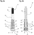
- FIGS. 2a and 2b show a further embodiment of an anchor bolt 10 according to the invention, wherein Figur2a a side view and FIG. 2b a sectional view along a line AA shows.
- a support pin 28 is disposed on an end face of the anchor portion 14, which is associated with the insertion end 24 of the anchor bolt 10.
- the support bolt 28 is connected to the anchor bolt 10, in particular to the anchor portion 14, by means of a thread 30. That is, the support bolt 28 is bolted to the anchor bolt 10.
- the expansion element 18 is held on the anchor portion 14 of the anchor bolt 10, so that the spreader element 18 is prevented from slipping off the anchor bolt 10.
- the anchor portion 14 has a receptacle with internal thread into which a pin of the support bolt 28 is screwed via a corresponding external thread.
- a buffer disc 32 is provided, which is arranged between the support bolt 28 and the end face of the anchor portion 14.
- the buffer disk 32 is compressible and thus allows under force a displacement of the expansion element 18 in the axial direction.
- the buffer disk 32 is partially against a stop formed by the anchor portion 14, so that the buffer disk 32 is clamped between the support bolt 28 and the anchor portion 14.
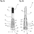
- FIGS. 3a and 3b show a further embodiment of an anchor bolt 10 according to the invention, wherein FIG. 3a a side view and FIG. 3b a sectional view along a line AA shows.
- FIGS. 3a and 3b embodiment shown differs from the previously described embodiments in that the anchor portion 14 and the shank portion 12 of the anchor bolt 10 as a separate Components are formed, which are coupled together to form the anchor bolt 10.
- anchor portion 14 and the shaft portion 12 are screwed together, wherein they have corresponding threads.
- the anchor portion 14 has a male portion including an external thread, which cooperates with an internal thread, which is provided in a receiving region of the shaft portion 12.
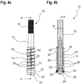
- FIGS. 4a and 4b show a further embodiment of an anchor bolt 10 according to the invention, wherein Figur4a a side view and FIG. 4b a sectional view along a line AA shows.
- the anchor portion 14 does not expand, but instead includes a thread 34 in the region in which the expansion element 18 is arranged.
- the thread 34 extends in the longitudinal direction of the anchor bolt 10 completely along the spreader 18 when it rests against the stop 20.
- the buffer slide 32 may be incompressible or compressible only to a very small extent in this embodiment, so that the expansion element 18 is already compressed and expanded at a slight twist.
- the expansion element 18 comprises substantially uniform cones 26.
- the cone 26 provided at the transition between the shank portion 12 and the anchor portion 14 is substantially similar to the cone 26 associated with the insertion end 24.
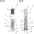
- FIGS. 5a and 5b show a further embodiment of an anchor bolt 10 according to the invention, wherein FIG. 5a a side view and FIG. 5b a sectional view along a line AA shows.
- the anchor portion 14 widens starting from the shaft portion 12 in the direction of the insertion end 24 and an anchor angle ⁇ . At the same time, the anchor portion 14 includes a thread 34 in the region in which the expansion element 18 is arranged.
- the expansion element 18 If the expansion element 18 is displaced radially relative to the armature section 14, the expansion element 18 rotates along the thread 34. Due to the widening of the anchor portion 14, the expansion element 18 is thereby widened.
- shaft portion 12 and anchor portion 14 By a separate design of shaft portion 12 and anchor portion 14, a modular system can be implemented. In this case, for example, different shaft sections 12 can be combined with an anchor section 14.
- FIG. 6a and 6b show a further embodiment of an anchor bolt 10 according to the invention, wherein FIG. 6a a side view and FIG. 6b a sectional view along a line AA shows.
- the anchor portion 14 is combined with a shank portion 12 having a different diameter compared to the previous embodiments.
- the shank portion 12 has a larger outer diameter than the anchor portion 14.
- the anchor portion 14 of in FIG. 6 substantially corresponds to the anchor portion 14 of in FIG. 5 In particular, both are the same.
- FIGS. 7a and 7b show a further embodiment of an anchor bolt 10 according to the invention, wherein Figure 7a a side view and FIG. 7b a sectional view along a line AA shows.
- the anchor portion 14 is as in the embodiment according to FIG. 4 provided with a thread 34 and runs straight, that is he does not widen.
- the size of the cones 26 increases from the shaft portion 12 toward the insertion end 24.
- both the initial diameter of the cones 26 and the outer diameter of the cones 26 increases from the shank portion 12 toward the shank end 24.
- FIGS. 8 shows a further embodiment of an anchor bolt 10 according to the invention in a sectional view.
- the anchor portion 14 tapers from the shank portion 12 toward the shank end 24, with the tapered portion 48 followed by a constant diameter portion 50.
- the tapered portion 48 serves as an assembly aid when attaching the expansion element 18.
- the amount of the taper corresponds to approximately 1/3 of the initial diameter.
- FIG. 9 shows a further embodiment of an anchor bolt 10 according to the invention in a partial sectional view.
- the expansion sleeve 18 is formed by a film 52, in particular a shrink film.
- the cones 26 of the expansion element 18 are formed by corresponding cones 54 in the anchor portion 14.
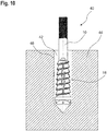
- FIG. 10 shows an inventive fastening system 40 with an anchor bolt 10 and a fixing mortar 42, wherein the anchor bolt 10 is anchored by means of fastening mortar 42 in a substrate 44.
- the fixing mortar 42 is introduced into a hole 46 into which the anchor bolt 10 is inserted, wherein the expansion element 18 is movable relative to the fastening mortar 42, in particular axially and / or radially relative to the fastening mortar 42 is displaceable.
- a release resistance between the expansion element 18 and the anchor portion 14 is less than or equal to the release resistance between the expansion element 18 and the attachment mortar 42nd
- any of the anchor bolts 10 shown above may be used.
Landscapes
- Engineering & Computer Science (AREA)
- General Engineering & Computer Science (AREA)
- Mechanical Engineering (AREA)
- Joining Of Building Structures In Genera (AREA)
- Dowels (AREA)
Priority Applications (1)
| Application Number | Priority Date | Filing Date | Title |
|---|---|---|---|
| EP18171981.6A EP3569876A1 (fr) | 2018-05-14 | 2018-05-14 | Boulon d'ancrage destiné à l'utilisation dans le mortier de fixation, système de fixation et procédé de fabrication d'un boulon d'ancrage |
Applications Claiming Priority (1)
| Application Number | Priority Date | Filing Date | Title |
|---|---|---|---|
| EP18171981.6A EP3569876A1 (fr) | 2018-05-14 | 2018-05-14 | Boulon d'ancrage destiné à l'utilisation dans le mortier de fixation, système de fixation et procédé de fabrication d'un boulon d'ancrage |
Publications (1)
| Publication Number | Publication Date |
|---|---|
| EP3569876A1 true EP3569876A1 (fr) | 2019-11-20 |
Family
ID=62167140
Family Applications (1)
| Application Number | Title | Priority Date | Filing Date |
|---|---|---|---|
| EP18171981.6A Withdrawn EP3569876A1 (fr) | 2018-05-14 | 2018-05-14 | Boulon d'ancrage destiné à l'utilisation dans le mortier de fixation, système de fixation et procédé de fabrication d'un boulon d'ancrage |
Country Status (1)
| Country | Link |
|---|---|
| EP (1) | EP3569876A1 (fr) |
Citations (8)
| Publication number | Priority date | Publication date | Assignee | Title |
|---|---|---|---|---|
| US2120577A (en) * | 1937-03-05 | 1938-06-14 | Rawlplug Company Inc | Machine screw anchor |
| EP0297228A1 (fr) * | 1987-06-13 | 1989-01-04 | Fischerwerke Arthur Fischer GmbH & Co. KG | Des chevilles à expansion, à ancrage dans des trous forés de forme conique s'évasant vers l'intérieur |
| EP0555542A1 (fr) * | 1992-02-13 | 1993-08-18 | fischerwerke Artur Fischer GmbH & Co. KG | Ancre pour l'ancrage au moyen d'une masse de liaison dans le trou prépercé d'une pièce en béton |
| DE9401970U1 (de) * | 1994-02-07 | 1994-03-24 | Häfele GmbH & Co, 72202 Nagold | Spreizbolzen |
| EP0665382A1 (fr) * | 1994-01-28 | 1995-08-02 | Fischerwerke Arthur Fischer GmbH & Co. KG | Dispositif d'ancrage à cheville expansible métallique et son procédé de fabrication |
| DE4430130A1 (de) * | 1994-08-25 | 1996-02-29 | Fischer Artur Werke Gmbh | Verfahren zur Herstellung von ineinandergreifenden Metallteilen |
| DE19523039A1 (de) * | 1995-06-24 | 1997-01-02 | Hilti Ag | Verfahren zum Erstellen einer spreizdruckfreien Verankerung |
| WO2008053542A1 (fr) * | 2006-10-31 | 2008-05-08 | Hinode Holdings Co., Ltd. | Pièce d'ancrage et son procédé d'ancrage et structure d'ancrage l'utilisant |
-
2018
- 2018-05-14 EP EP18171981.6A patent/EP3569876A1/fr not_active Withdrawn
Patent Citations (8)
| Publication number | Priority date | Publication date | Assignee | Title |
|---|---|---|---|---|
| US2120577A (en) * | 1937-03-05 | 1938-06-14 | Rawlplug Company Inc | Machine screw anchor |
| EP0297228A1 (fr) * | 1987-06-13 | 1989-01-04 | Fischerwerke Arthur Fischer GmbH & Co. KG | Des chevilles à expansion, à ancrage dans des trous forés de forme conique s'évasant vers l'intérieur |
| EP0555542A1 (fr) * | 1992-02-13 | 1993-08-18 | fischerwerke Artur Fischer GmbH & Co. KG | Ancre pour l'ancrage au moyen d'une masse de liaison dans le trou prépercé d'une pièce en béton |
| EP0665382A1 (fr) * | 1994-01-28 | 1995-08-02 | Fischerwerke Arthur Fischer GmbH & Co. KG | Dispositif d'ancrage à cheville expansible métallique et son procédé de fabrication |
| DE9401970U1 (de) * | 1994-02-07 | 1994-03-24 | Häfele GmbH & Co, 72202 Nagold | Spreizbolzen |
| DE4430130A1 (de) * | 1994-08-25 | 1996-02-29 | Fischer Artur Werke Gmbh | Verfahren zur Herstellung von ineinandergreifenden Metallteilen |
| DE19523039A1 (de) * | 1995-06-24 | 1997-01-02 | Hilti Ag | Verfahren zum Erstellen einer spreizdruckfreien Verankerung |
| WO2008053542A1 (fr) * | 2006-10-31 | 2008-05-08 | Hinode Holdings Co., Ltd. | Pièce d'ancrage et son procédé d'ancrage et structure d'ancrage l'utilisant |
Similar Documents
| Publication | Publication Date | Title |
|---|---|---|
| EP2309138B1 (fr) | Piton à expansion | |
| EP3047161B1 (fr) | Ancre extensible | |
| EP2514979B1 (fr) | cheville à expansion | |
| EP2110565A2 (fr) | Composant de raccordement destiné à la fixation d'un élément de construction sur un élément de support | |
| CH656193A5 (de) | Spreizduebel. | |
| WO1982004461A1 (fr) | Boulon d'ancrage | |
| WO2014166784A1 (fr) | Système d'ancrage | |
| EP0926360B1 (fr) | Cheville pour trou d'ancrage à contre-dépouille | |
| EP1412644B1 (fr) | Cheville a expansion | |
| WO2001066962A1 (fr) | Cheville a expansion | |
| WO2004072495A1 (fr) | Systeme d'ancrage a contre-depouille pouvant etre mis en place par liaison de forme | |
| WO2020120196A1 (fr) | Cheville à expansion | |
| EP2119919B1 (fr) | Agencement de fixation | |
| EP0381678B1 (fr) | Cheville a contre-depouille | |
| DE3741345C2 (de) | Verankerungsverfahren für Befestigungselemente | |
| EP3569876A1 (fr) | Boulon d'ancrage destiné à l'utilisation dans le mortier de fixation, système de fixation et procédé de fabrication d'un boulon d'ancrage | |
| EP1872020B1 (fr) | Cheville pour ancrage dans des materiaux de construction en dur | |
| DE19744728A1 (de) | Einschlagdübel | |
| EP0070976B1 (fr) | Cheville d'extension et coup | |
| EP0245865B1 (fr) | Procédé de pose d'une goupille d'ancrage dans un trou foré d'un support et goupille d'ancrage à utiliser avec ce procédé | |
| DE102009006207A1 (de) | Befestigungsanordnung und Befestigungselement | |
| WO2001061198A1 (fr) | Cheville a expansion | |
| DE102013103429A1 (de) | Dämmstoffhalter | |
| DE19720033A1 (de) | Spreizanker zum Befestigen an einem Hohlkammern aufweisenden Bauwerk | |
| DE19900676C2 (de) | Anker zur Verankerung in einer Verbundmasse |
Legal Events
| Date | Code | Title | Description |
|---|---|---|---|
| PUAI | Public reference made under article 153(3) epc to a published international application that has entered the european phase |
Free format text: ORIGINAL CODE: 0009012 |
|
| AK | Designated contracting states |
Kind code of ref document: A1 Designated state(s): AL AT BE BG CH CY CZ DE DK EE ES FI FR GB GR HR HU IE IS IT LI LT LU LV MC MK MT NL NO PL PT RO RS SE SI SK SM TR |
|
| AX | Request for extension of the european patent |
Extension state: BA ME |
|
| STAA | Information on the status of an ep patent application or granted ep patent |
Free format text: STATUS: THE APPLICATION IS DEEMED TO BE WITHDRAWN |
|
| 18D | Application deemed to be withdrawn |
Effective date: 20200603 |