EP3569885B1 - Embrayage à griffes - Google Patents
Embrayage à griffes Download PDFInfo
- Publication number
- EP3569885B1 EP3569885B1 EP19184226.9A EP19184226A EP3569885B1 EP 3569885 B1 EP3569885 B1 EP 3569885B1 EP 19184226 A EP19184226 A EP 19184226A EP 3569885 B1 EP3569885 B1 EP 3569885B1
- Authority
- EP
- European Patent Office
- Prior art keywords
- spline
- splines
- row
- dog clutch
- internal
- Prior art date
- Legal status (The legal status is an assumption and is not a legal conclusion. Google has not performed a legal analysis and makes no representation as to the accuracy of the status listed.)
- Not-in-force
Links
- 230000009977 dual effect Effects 0.000 claims description 17
- 230000013011 mating Effects 0.000 claims description 8
- 210000000078 claw Anatomy 0.000 description 7
- 230000009286 beneficial effect Effects 0.000 description 1
- 238000004519 manufacturing process Methods 0.000 description 1
Images


Classifications
-
- F—MECHANICAL ENGINEERING; LIGHTING; HEATING; WEAPONS; BLASTING
- F16—ENGINEERING ELEMENTS AND UNITS; GENERAL MEASURES FOR PRODUCING AND MAINTAINING EFFECTIVE FUNCTIONING OF MACHINES OR INSTALLATIONS; THERMAL INSULATION IN GENERAL
- F16D—COUPLINGS FOR TRANSMITTING ROTATION; CLUTCHES; BRAKES
- F16D11/00—Clutches in which the members have interengaging parts
- F16D11/08—Clutches in which the members have interengaging parts actuated by moving a non-rotating part axially
- F16D11/10—Clutches in which the members have interengaging parts actuated by moving a non-rotating part axially with clutching members movable only axially
-
- F—MECHANICAL ENGINEERING; LIGHTING; HEATING; WEAPONS; BLASTING
- F16—ENGINEERING ELEMENTS AND UNITS; GENERAL MEASURES FOR PRODUCING AND MAINTAINING EFFECTIVE FUNCTIONING OF MACHINES OR INSTALLATIONS; THERMAL INSULATION IN GENERAL
- F16D—COUPLINGS FOR TRANSMITTING ROTATION; CLUTCHES; BRAKES
- F16D11/00—Clutches in which the members have interengaging parts
- F16D11/14—Clutches in which the members have interengaging parts with clutching members movable only axially
-
- F—MECHANICAL ENGINEERING; LIGHTING; HEATING; WEAPONS; BLASTING
- F16—ENGINEERING ELEMENTS AND UNITS; GENERAL MEASURES FOR PRODUCING AND MAINTAINING EFFECTIVE FUNCTIONING OF MACHINES OR INSTALLATIONS; THERMAL INSULATION IN GENERAL
- F16D—COUPLINGS FOR TRANSMITTING ROTATION; CLUTCHES; BRAKES
- F16D11/00—Clutches in which the members have interengaging parts
- F16D2011/004—Clutches in which the members have interengaging parts using an internal or intermediate axially slidable sleeve, coupling both components together, whereby the intermediate sleeve is arranged internally at least with respect to one of the components
-
- F—MECHANICAL ENGINEERING; LIGHTING; HEATING; WEAPONS; BLASTING
- F16—ENGINEERING ELEMENTS AND UNITS; GENERAL MEASURES FOR PRODUCING AND MAINTAINING EFFECTIVE FUNCTIONING OF MACHINES OR INSTALLATIONS; THERMAL INSULATION IN GENERAL
- F16D—COUPLINGS FOR TRANSMITTING ROTATION; CLUTCHES; BRAKES
- F16D11/00—Clutches in which the members have interengaging parts
- F16D2011/008—Clutches in which the members have interengaging parts characterised by the form of the teeth forming the inter-engaging parts; Details of shape or structure of these teeth
-
- F—MECHANICAL ENGINEERING; LIGHTING; HEATING; WEAPONS; BLASTING
- F16—ENGINEERING ELEMENTS AND UNITS; GENERAL MEASURES FOR PRODUCING AND MAINTAINING EFFECTIVE FUNCTIONING OF MACHINES OR INSTALLATIONS; THERMAL INSULATION IN GENERAL
- F16D—COUPLINGS FOR TRANSMITTING ROTATION; CLUTCHES; BRAKES
- F16D23/00—Details of mechanically-actuated clutches not specific for one distinct type
- F16D23/12—Mechanical clutch-actuating mechanisms arranged outside the clutch as such
Definitions
- the present invention relates to a dog clutch comprising first and second drive shafts, the drive shafts being connectable to one another by a dual spline connector which is movable along a longitudinal axis of the first and second drive shafts.
- the dual spline connector is provided with an internal spline that mates with an external spline of the first drive shaft, the dual spline connector further being provided with an external spline that upon axial movement may be connected or disconnected to an internal spline of the second drive shaft.
- Clutches are used to connect or disconnect a drive source, e.g. an engine, to a driving means, e.g. a drive shaft of a vehicle.
- a drive source e.g. an engine
- driving means e.g. a drive shaft of a vehicle.
- clutches There are two main types of clutches, namely friction clutches, which allows for a slip between the drive source and the driving means, and dog clutches, which are either connected or disconnected.
- Most dog clutches are designed with some kind of claws, often in the form of splines on a shaft, that may be engaged to a corresponding structure on another shaft.
- dog clutches require the rotational speeds of the driving source and the driving means to be fairly equal; if not, the claws may not be engaged to the corresponding structure of the other shaft, since the claws will "bounce" on the corresponding structure they are supposed to engage with, without properly engaging for transferring the torque to be transferred.
- dog clutches One common field of use for dog clutches is in four wheel drive applications, where it is beneficial if it is possible to shift between two wheel drive and four wheel drive. This is performed by engaging or disengaging the engine from either driving the front wheels or the rear wheels.
- One solution to the problem with engagement if the rotational speeds of the shafts to be connected are not equal is to design the dog clutch with a "slack", i.e. to increase the gaps of the corresponding structure.
- the dog clutch may be "clonky”, i.e. provide for a torque transfer interruption during torque shift from a negative to a positive torque or vice versa.
- a dog clutch wherein the claws are maximum half the size of the openings they are supposed to mate with are arranged with springs urging the claws to an extended position. If the rotational speeds of the shafts to be connected are different, the connection will start by one of the claws entering the opening with which it is supposed to mate, after which a neighboring claw also will enter the opening, hence creating a "clonk" free connection.
- the present invention solves, or at least mitigates, the problems of the prior art by providing a dog clutch wherein either or both of the external spline of the dual spline connector and/or the internal spline of the second drive shaft is or are provided with means for allowing partial connection of the internal and external splines in accordance with appended claim 1.
- the means for allowing partial connection of the internal and external splines is a recess provided at an end of the spline that is arranged to contact a mating spline, wherein the recess comprises a torque transferring surface and a bottom surface.
- the torque transferring surface may have a shape corresponding to the spline it is arranged to contact.
- the recess may be placed on a side of the spline being opposite to the side of the spline intended to transfer torque in a main direction.
- both the internal splines and the external splines are divided into at least two rows.
- one of the spline rows may connect to its mating spline row earlier than the other spline row.
- the splines of the spline row that will connect to its mating spline row earlier than the other spline row may be provided with thinner splines than the other spline row.
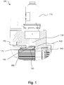
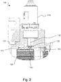
- connection/disconnection arrangement 100 of a dog clutch is shown in a section view.
- the connection/disconnection arrangement 100 comprises a control unit 110, which is operable to rotate an excentrically disposed control pin 120 about a central axis 130.
- the control pin is further connected to a circumferential track 140 of a dual spline connector 150, which is longitudinally glidably mounted on a central splined drive shaft 160.
- An internal surface of the dual spline connector 150 is provided with internal splines mating with the splines of the splined drive shaft 160, such that the dual spline connector at all times co-rotate with the splined drive shaft, but as mentioned, it may glide in the longitudinal direction, i.e. along the length axis of the splined drive shaft.
- the dual spline connector is connectable to a second drive shaft 170.
- the second drive shaft is provided with an internal spline 175, and the dual spline connector 150 is provided with an external spline 155 that mates with the internal spline 175 of the second drive shaft 170.
- the dog clutch is in the disconnected state. This is achieved by rotating the control unit 110 such that the pin 120 reaches its position to the right in fig. 1 . Due to the cooperation between the pin 120 and the track 140, the dual spline connector will be forced to the right in fig. 1 , away from the internal splines 175 of the second drive shaft 170.
- the control unit In order to connect the splined drive shaft and the second drive shaft to one another, the control unit is controlled to rotate such that the pin 120, and consequently the dual spline connector 150, to the left. Then, the internal splines 175 of the second drive shaft and the external splines of the dual spline connector will engage, and the rotation of the splined drive shaft and the second drive shaft will be identical.
- this is solved by making the ends of either or both of the external and/or internal splines that first meet one another during a connecting operation asymmetric.
- Figs. 3a-3g show an exemplary spline design for facilitating connection between the internal spline 175 and the external spline 155.
- the external splines are provided with a recess 157, which allows the splines to become partly engaged without being perfectly aligned.
- the recess provides a torque transferring surface and a bottom surface, the torque transferring surface having a shape adapted to provide for an as large surface area as possible contacting the internal spline 175.
- the recess 157 preferably is located on the side of the spline that does not transfer force to its mating spline. Moreover, is preferred if the bottom surface is fairly flat.
- Figs. 3a-3g show a connection sequence for a situation wherein the rotational speed of the splines 155 is initially higher than the rotational speed of the internal splines 175.
- control unit is controlled to rotate, such that the splines start to contact. As can be seen, the splines do not lock to one another, since they are not aligned.
- Fig. 3c it is shown how the splines 155 have moved relative the splines 175 such that the splines 175 are aligned to the recess 157.
- the recesses 157 allow for the initial engagement of the splines - if it would not be present, the time of alignment between the splines would be too short for the splines to engage properly.
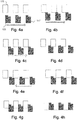
- Figs. 4a-4c a connection sequence for the opposite rotational speed difference of the splines 155 and 175 is shown, i.e. when the rotational speed being lower for the splines 155.
- the sequence of events for figs 4a-4c is identical to the sequence of events for figs. 3a-3c , but then it differs slightly:
- Fig. 4d the splines have been aligned, but instead of engagement between the splines 155 and 175, there will be an engagement between the recess 157 and the spline 175.
- this position is limited to use in situations where the torque transferred by the dog clutch is limited, e.g. in the direction wherein engine brake rather than engine drive is present.
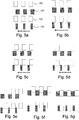
- Figs. 5a-5g an embodiment of the spline arrangement is shown.
- the functionality will be given.
- Fig. 5c the splines of the spline row 185 have been aligned with the splines of the spline row 195, meaning that it is possible for the ends of the splines 185 to enter the space between the splines 195. This is done in Fig. 5d .
- Fig. 5e the ends of the splines of the spline row 195 has contacted the splines 185, hence forcing the spline row 185 to co-rotate with the spline row 185. This will allow for the splines of the spline row 180 to mate with the splines of spline row 190 ( figs. 5f and 5g ).
- connection sequence will be equal to the connection sequence as disclosed in conjunction with Figs. 4a-4h , i.e. a reverse of the transferred torque will be required for the splines to come into complete contact.
- this is shown in Figs. 6a to 6i .
- a dog clutch allowing for both "clonk” free connection and connection of the dog clutch also when there is a difference of the rotational speeds of the drive shaft of the dog clutch is provided.
Landscapes
- Engineering & Computer Science (AREA)
- General Engineering & Computer Science (AREA)
- Mechanical Engineering (AREA)
- Mechanical Operated Clutches (AREA)
- Arrangement And Driving Of Transmission Devices (AREA)
Claims (4)
- Embrayage à griffes comprenant des premier (160) et second (170) arbres de transmission, les arbres de transmission pouvant être accouplés l'un avec l'autre par un connecteur à double cannelure (150) qui est mobile le long d'un axe longitudinal des premier (160) et second (170) arbres de transmission et pourvu d'une cannelure interne qui s'accouple avec une cannelure externe du premier arbre de transmission, le connecteur à double cannelure étant en outre pourvu d'une cannelure externe qui, lors d'un déplacement axial, peut être accouplée avec une cannelure interne du second arbre de transmission ou désaccouplée de cette dernière, dans lequel l'une ou l'autre, ou les deux, de la cannelure externe du connecteur à double cannelure et/ou de la cannelure interne du second arbre de transmission est ou sont pourvues d'un moyen destiné à permettre un accouplement partiel des cannelures interne et externe, caractérisé en ce que
les cannelures internes et les cannelures externes sont toutes les deux divisées en au moins deux rangées. - Embrayage à griffes selon la revendication 1, dans lequel l'une des rangées de cannelures s'accouple avec sa rangée de cannelures complémentaire avant l'autre rangée de cannelures.
- Embrayage à griffes selon la revendication 2, dans lequel la rangée de cannelures qui s'accouplera à sa rangée de cannelures complémentaire avant l'autre rangée de cannelures est pourvue de cannelures plus minces que l'autre rangée de cannelures.
- Embrayage à griffes selon la revendication 3, dans lequel les cannelures de la rangée de cannelures s'accouplant avant avec sa rangée de cannelures complémentaire sont situées de sorte qu'elles favoriseront un transfert de couple lors d'un transfert de couple de l'embrayage à griffes dans une direction principale.
Applications Claiming Priority (3)
| Application Number | Priority Date | Filing Date | Title |
|---|---|---|---|
| SE1451546A SE540508C2 (en) | 2014-12-15 | 2014-12-15 | Dog clutch with means for allowing partial connection |
| EP15808637.1A EP3234392B1 (fr) | 2014-12-15 | 2015-12-14 | Embrayage à griffes |
| PCT/EP2015/079665 WO2016096769A1 (fr) | 2014-12-15 | 2015-12-14 | Embrayage à griffes |
Related Parent Applications (1)
| Application Number | Title | Priority Date | Filing Date |
|---|---|---|---|
| EP15808637.1A Division EP3234392B1 (fr) | 2014-12-15 | 2015-12-14 | Embrayage à griffes |
Publications (2)
| Publication Number | Publication Date |
|---|---|
| EP3569885A1 EP3569885A1 (fr) | 2019-11-20 |
| EP3569885B1 true EP3569885B1 (fr) | 2021-01-20 |
Family
ID=54849929
Family Applications (2)
| Application Number | Title | Priority Date | Filing Date |
|---|---|---|---|
| EP19184226.9A Not-in-force EP3569885B1 (fr) | 2014-12-15 | 2015-12-14 | Embrayage à griffes |
| EP15808637.1A Not-in-force EP3234392B1 (fr) | 2014-12-15 | 2015-12-14 | Embrayage à griffes |
Family Applications After (1)
| Application Number | Title | Priority Date | Filing Date |
|---|---|---|---|
| EP15808637.1A Not-in-force EP3234392B1 (fr) | 2014-12-15 | 2015-12-14 | Embrayage à griffes |
Country Status (7)
| Country | Link |
|---|---|
| US (1) | US10487883B2 (fr) |
| EP (2) | EP3569885B1 (fr) |
| JP (1) | JP2017538903A (fr) |
| KR (1) | KR20170094394A (fr) |
| CN (1) | CN107208704B (fr) |
| SE (1) | SE540508C2 (fr) |
| WO (1) | WO2016096769A1 (fr) |
Families Citing this family (3)
| Publication number | Priority date | Publication date | Assignee | Title |
|---|---|---|---|---|
| FR3167678A1 (fr) | 2024-10-21 | 2026-04-24 | Valeo Embrayages | Système d’accouplement d’arbres de transmission |
| FR3167679A1 (fr) | 2024-10-21 | 2026-04-24 | Valeo Embrayages | Système d’accouplement d’arbres de transmission |
| FR3167677A1 (fr) | 2024-10-21 | 2026-04-24 | Valeo Embrayages | Système d’accouplement d’arbres de transmission et procédé de commande d’un tel système d’accouplement d’arbres de transmission |
Family Cites Families (20)
| Publication number | Priority date | Publication date | Assignee | Title |
|---|---|---|---|---|
| GB542439A (en) * | 1940-06-05 | 1942-01-09 | Chrysler Corp | Improvements in or relating to power transmissions for driving vehicles |
| GB975298A (en) * | 1962-11-20 | 1964-11-11 | Vauxhall Motors Ltd | Improvements relating to sleeve clutch assemblies |
| GB1291773A (en) * | 1970-03-11 | 1972-10-04 | Sss Patents Ltd | Synchronous self-shifting clutches |
| US3651907A (en) * | 1970-08-03 | 1972-03-28 | Boise Cascade Corp | Overrunning clutch for transfer case transmission |
| JPS49104320U (fr) * | 1972-12-28 | 1974-09-06 | ||
| GB1476696A (en) * | 1974-10-11 | 1977-06-16 | Sss Patents Ltd | Synchronous self-shifting toothed clutch |
| US4727968A (en) * | 1986-10-14 | 1988-03-01 | General Motors Corporation | Synchronizer clutch assembly |
| CH677819A5 (fr) * | 1988-12-22 | 1991-06-28 | Maag Zahnraeder & Maschinen Ag | |
| DE3904158A1 (de) | 1989-02-11 | 1990-08-16 | Neuenstein Zahnradwerk | Klauenkupplung |
| JPH04116023U (ja) * | 1991-03-29 | 1992-10-15 | セイレイ工業株式会社 | 爪クラツチ構造 |
| US6193629B1 (en) * | 1999-05-07 | 2001-02-27 | Ford Global Technologies, Inc. | Shifting mechanism |
| CN2643069Y (zh) * | 2003-02-20 | 2004-09-22 | 湘潭大学 | 梯形摩擦离合器 |
| CN2743605Y (zh) * | 2004-08-03 | 2005-11-30 | 刘守元 | 爪式离合器 |
| JP2008248980A (ja) * | 2007-03-29 | 2008-10-16 | Toyota Motor Corp | 切り替え機構、ならびに車両用のトランスファ |
| JP2010242895A (ja) * | 2009-04-07 | 2010-10-28 | Honda Motor Co Ltd | ドグクラッチ部噛み合い構造 |
| DE102010039445A1 (de) * | 2010-08-18 | 2012-02-23 | Zf Friedrichshafen Ag | Vorrichtung zum formschlüssigen drehfesten Verbinden von mindestens zwei Bauelementen mit zwei Schaltelementhälften |
| DE102010043592A1 (de) * | 2010-11-09 | 2012-05-10 | Zf Friedrichshafen Ag | Formschlüssiges Schaltelement |
| DE102012216988A1 (de) | 2012-09-21 | 2014-04-10 | Zf Friedrichshafen Ag | Klauenkupplung |
| WO2014182446A1 (fr) | 2013-05-08 | 2014-11-13 | Schaeffler Technologies Gmbh & Co. Kg | Dispositif de coupure de transfert d'energie rotative |
| CN103742562A (zh) * | 2014-01-11 | 2014-04-23 | 中国船舶重工集团公司第七�三研究所 | 同步自动离合器棘轮棘爪结构 |
-
2014
- 2014-12-15 SE SE1451546A patent/SE540508C2/en not_active IP Right Cessation
-
2015
- 2015-12-14 EP EP19184226.9A patent/EP3569885B1/fr not_active Not-in-force
- 2015-12-14 US US15/535,930 patent/US10487883B2/en not_active Expired - Fee Related
- 2015-12-14 JP JP2017531679A patent/JP2017538903A/ja not_active Ceased
- 2015-12-14 WO PCT/EP2015/079665 patent/WO2016096769A1/fr not_active Ceased
- 2015-12-14 EP EP15808637.1A patent/EP3234392B1/fr not_active Not-in-force
- 2015-12-14 KR KR1020177019277A patent/KR20170094394A/ko not_active Withdrawn
- 2015-12-14 CN CN201580068273.2A patent/CN107208704B/zh not_active Expired - Fee Related
Non-Patent Citations (1)
| Title |
|---|
| None * |
Also Published As
| Publication number | Publication date |
|---|---|
| EP3569885A1 (fr) | 2019-11-20 |
| SE540508C2 (en) | 2018-09-25 |
| US10487883B2 (en) | 2019-11-26 |
| US20170363155A1 (en) | 2017-12-21 |
| CN107208704A (zh) | 2017-09-26 |
| CN107208704B (zh) | 2019-10-08 |
| WO2016096769A1 (fr) | 2016-06-23 |
| KR20170094394A (ko) | 2017-08-17 |
| SE1451546A1 (en) | 2016-06-16 |
| EP3234392B1 (fr) | 2019-07-24 |
| JP2017538903A (ja) | 2017-12-28 |
| EP3234392A1 (fr) | 2017-10-25 |
Similar Documents
| Publication | Publication Date | Title |
|---|---|---|
| CN105508565B (zh) | 具有分离式车桥的全轮驱动传动系统 | |
| US10883547B2 (en) | Dog clutch and transmission | |
| CN102834634B (zh) | 离合器设备 | |
| CN106132752B (zh) | 用于四轮驱动车辆的分动器 | |
| CN103867658B (zh) | 变速器及其离合器组件 | |
| EP2883736A1 (fr) | Boîte de transfert entraînée par moteur avec actionnement concentrique | |
| EP2749784A1 (fr) | Plaque d'embrayage | |
| US8640842B2 (en) | Clutch plate having integrated separating feature | |
| US8899395B2 (en) | Selectable one-way torque transmitting device using control rail | |
| CN104565101A (zh) | 带有爪式端面离合器的致动器 | |
| CN112638767B (zh) | 传动装置 | |
| JP7526729B2 (ja) | トランスミッション・システム | |
| EP3234392B1 (fr) | Embrayage à griffes | |
| CN115485159A (zh) | 传动系 | |
| CN108691926A (zh) | 扭矩限制器 | |
| US11073181B2 (en) | Transmission and method for shifting a transmission | |
| US3365039A (en) | Positive-clutch synchroniser mechanism | |
| CN107848413B (zh) | 由同步事件提供动力的传动系统致动器 | |
| JP2008248980A (ja) | 切り替え機構、ならびに車両用のトランスファ | |
| JP2025535863A (ja) | 選択接続組立体を伴う駆動系構成要素 | |
| JPH035720Y2 (fr) | ||
| US20250137496A1 (en) | System and methods for a clutch system based on an axially slidable sleeve and radially translatable key | |
| KR101496565B1 (ko) | 4륜 구동차량의 부변속기용 동력연결 구동장치 | |
| KR101804052B1 (ko) | 차량 변속기용 동기장치 | |
| KR20000011250A (ko) | 클러치링메카니즘 |
Legal Events
| Date | Code | Title | Description |
|---|---|---|---|
| PUAI | Public reference made under article 153(3) epc to a published international application that has entered the european phase |
Free format text: ORIGINAL CODE: 0009012 |
|
| STAA | Information on the status of an ep patent application or granted ep patent |
Free format text: STATUS: THE APPLICATION HAS BEEN PUBLISHED |
|
| AC | Divisional application: reference to earlier application |
Ref document number: 3234392 Country of ref document: EP Kind code of ref document: P |
|
| AK | Designated contracting states |
Kind code of ref document: A1 Designated state(s): AL AT BE BG CH CY CZ DE DK EE ES FI FR GB GR HR HU IE IS IT LI LT LU LV MC MK MT NL NO PL PT RO RS SE SI SK SM TR |
|
| STAA | Information on the status of an ep patent application or granted ep patent |
Free format text: STATUS: REQUEST FOR EXAMINATION WAS MADE |
|
| 17P | Request for examination filed |
Effective date: 20200513 |
|
| RBV | Designated contracting states (corrected) |
Designated state(s): AL AT BE BG CH CY CZ DE DK EE ES FI FR GB GR HR HU IE IS IT LI LT LU LV MC MK MT NL NO PL PT RO RS SE SI SK SM TR |
|
| GRAP | Despatch of communication of intention to grant a patent |
Free format text: ORIGINAL CODE: EPIDOSNIGR1 |
|
| STAA | Information on the status of an ep patent application or granted ep patent |
Free format text: STATUS: GRANT OF PATENT IS INTENDED |
|
| RIC1 | Information provided on ipc code assigned before grant |
Ipc: F16D 11/14 20060101AFI20200707BHEP |
|
| INTG | Intention to grant announced |
Effective date: 20200720 |
|
| GRAS | Grant fee paid |
Free format text: ORIGINAL CODE: EPIDOSNIGR3 |
|
| GRAA | (expected) grant |
Free format text: ORIGINAL CODE: 0009210 |
|
| STAA | Information on the status of an ep patent application or granted ep patent |
Free format text: STATUS: THE PATENT HAS BEEN GRANTED |
|
| AC | Divisional application: reference to earlier application |
Ref document number: 3234392 Country of ref document: EP Kind code of ref document: P |
|
| AK | Designated contracting states |
Kind code of ref document: B1 Designated state(s): AL AT BE BG CH CY CZ DE DK EE ES FI FR GB GR HR HU IE IS IT LI LT LU LV MC MK MT NL NO PL PT RO RS SE SI SK SM TR |
|
| REG | Reference to a national code |
Ref country code: GB Ref legal event code: FG4D |
|
| REG | Reference to a national code |
Ref country code: CH Ref legal event code: EP |
|
| REG | Reference to a national code |
Ref country code: AT Ref legal event code: REF Ref document number: 1356668 Country of ref document: AT Kind code of ref document: T Effective date: 20210215 |
|
| REG | Reference to a national code |
Ref country code: IE Ref legal event code: FG4D |
|
| REG | Reference to a national code |
Ref country code: DE Ref legal event code: R096 Ref document number: 602015065140 Country of ref document: DE |
|
| REG | Reference to a national code |
Ref country code: NL Ref legal event code: MP Effective date: 20210120 |
|
| REG | Reference to a national code |
Ref country code: LT Ref legal event code: MG9D |
|
| REG | Reference to a national code |
Ref country code: AT Ref legal event code: MK05 Ref document number: 1356668 Country of ref document: AT Kind code of ref document: T Effective date: 20210120 |
|
| PG25 | Lapsed in a contracting state [announced via postgrant information from national office to epo] |
Ref country code: LT Free format text: LAPSE BECAUSE OF FAILURE TO SUBMIT A TRANSLATION OF THE DESCRIPTION OR TO PAY THE FEE WITHIN THE PRESCRIBED TIME-LIMIT Effective date: 20210120 Ref country code: PT Free format text: LAPSE BECAUSE OF FAILURE TO SUBMIT A TRANSLATION OF THE DESCRIPTION OR TO PAY THE FEE WITHIN THE PRESCRIBED TIME-LIMIT Effective date: 20210520 Ref country code: NO Free format text: LAPSE BECAUSE OF FAILURE TO SUBMIT A TRANSLATION OF THE DESCRIPTION OR TO PAY THE FEE WITHIN THE PRESCRIBED TIME-LIMIT Effective date: 20210420 Ref country code: BG Free format text: LAPSE BECAUSE OF FAILURE TO SUBMIT A TRANSLATION OF THE DESCRIPTION OR TO PAY THE FEE WITHIN THE PRESCRIBED TIME-LIMIT Effective date: 20210420 Ref country code: HR Free format text: LAPSE BECAUSE OF FAILURE TO SUBMIT A TRANSLATION OF THE DESCRIPTION OR TO PAY THE FEE WITHIN THE PRESCRIBED TIME-LIMIT Effective date: 20210120 Ref country code: GR Free format text: LAPSE BECAUSE OF FAILURE TO SUBMIT A TRANSLATION OF THE DESCRIPTION OR TO PAY THE FEE WITHIN THE PRESCRIBED TIME-LIMIT Effective date: 20210421 Ref country code: FI Free format text: LAPSE BECAUSE OF FAILURE TO SUBMIT A TRANSLATION OF THE DESCRIPTION OR TO PAY THE FEE WITHIN THE PRESCRIBED TIME-LIMIT Effective date: 20210120 |
|
| PG25 | Lapsed in a contracting state [announced via postgrant information from national office to epo] |
Ref country code: RS Free format text: LAPSE BECAUSE OF FAILURE TO SUBMIT A TRANSLATION OF THE DESCRIPTION OR TO PAY THE FEE WITHIN THE PRESCRIBED TIME-LIMIT Effective date: 20210120 Ref country code: SE Free format text: LAPSE BECAUSE OF FAILURE TO SUBMIT A TRANSLATION OF THE DESCRIPTION OR TO PAY THE FEE WITHIN THE PRESCRIBED TIME-LIMIT Effective date: 20210120 Ref country code: LV Free format text: LAPSE BECAUSE OF FAILURE TO SUBMIT A TRANSLATION OF THE DESCRIPTION OR TO PAY THE FEE WITHIN THE PRESCRIBED TIME-LIMIT Effective date: 20210120 Ref country code: PL Free format text: LAPSE BECAUSE OF FAILURE TO SUBMIT A TRANSLATION OF THE DESCRIPTION OR TO PAY THE FEE WITHIN THE PRESCRIBED TIME-LIMIT Effective date: 20210120 Ref country code: AT Free format text: LAPSE BECAUSE OF FAILURE TO SUBMIT A TRANSLATION OF THE DESCRIPTION OR TO PAY THE FEE WITHIN THE PRESCRIBED TIME-LIMIT Effective date: 20210120 |
|
| PG25 | Lapsed in a contracting state [announced via postgrant information from national office to epo] |
Ref country code: IS Free format text: LAPSE BECAUSE OF FAILURE TO SUBMIT A TRANSLATION OF THE DESCRIPTION OR TO PAY THE FEE WITHIN THE PRESCRIBED TIME-LIMIT Effective date: 20210520 |
|
| REG | Reference to a national code |
Ref country code: DE Ref legal event code: R097 Ref document number: 602015065140 Country of ref document: DE |
|
| PG25 | Lapsed in a contracting state [announced via postgrant information from national office to epo] |
Ref country code: SM Free format text: LAPSE BECAUSE OF FAILURE TO SUBMIT A TRANSLATION OF THE DESCRIPTION OR TO PAY THE FEE WITHIN THE PRESCRIBED TIME-LIMIT Effective date: 20210120 Ref country code: CZ Free format text: LAPSE BECAUSE OF FAILURE TO SUBMIT A TRANSLATION OF THE DESCRIPTION OR TO PAY THE FEE WITHIN THE PRESCRIBED TIME-LIMIT Effective date: 20210120 Ref country code: EE Free format text: LAPSE BECAUSE OF FAILURE TO SUBMIT A TRANSLATION OF THE DESCRIPTION OR TO PAY THE FEE WITHIN THE PRESCRIBED TIME-LIMIT Effective date: 20210120 |
|
| PLBE | No opposition filed within time limit |
Free format text: ORIGINAL CODE: 0009261 |
|
| STAA | Information on the status of an ep patent application or granted ep patent |
Free format text: STATUS: NO OPPOSITION FILED WITHIN TIME LIMIT |
|
| PG25 | Lapsed in a contracting state [announced via postgrant information from national office to epo] |
Ref country code: RO Free format text: LAPSE BECAUSE OF FAILURE TO SUBMIT A TRANSLATION OF THE DESCRIPTION OR TO PAY THE FEE WITHIN THE PRESCRIBED TIME-LIMIT Effective date: 20210120 Ref country code: SK Free format text: LAPSE BECAUSE OF FAILURE TO SUBMIT A TRANSLATION OF THE DESCRIPTION OR TO PAY THE FEE WITHIN THE PRESCRIBED TIME-LIMIT Effective date: 20210120 Ref country code: DK Free format text: LAPSE BECAUSE OF FAILURE TO SUBMIT A TRANSLATION OF THE DESCRIPTION OR TO PAY THE FEE WITHIN THE PRESCRIBED TIME-LIMIT Effective date: 20210120 |
|
| 26N | No opposition filed |
Effective date: 20211021 |
|
| PG25 | Lapsed in a contracting state [announced via postgrant information from national office to epo] |
Ref country code: ES Free format text: LAPSE BECAUSE OF FAILURE TO SUBMIT A TRANSLATION OF THE DESCRIPTION OR TO PAY THE FEE WITHIN THE PRESCRIBED TIME-LIMIT Effective date: 20210120 Ref country code: AL Free format text: LAPSE BECAUSE OF FAILURE TO SUBMIT A TRANSLATION OF THE DESCRIPTION OR TO PAY THE FEE WITHIN THE PRESCRIBED TIME-LIMIT Effective date: 20210120 |
|
| PG25 | Lapsed in a contracting state [announced via postgrant information from national office to epo] |
Ref country code: SI Free format text: LAPSE BECAUSE OF FAILURE TO SUBMIT A TRANSLATION OF THE DESCRIPTION OR TO PAY THE FEE WITHIN THE PRESCRIBED TIME-LIMIT Effective date: 20210120 |
|
| PG25 | Lapsed in a contracting state [announced via postgrant information from national office to epo] |
Ref country code: IT Free format text: LAPSE BECAUSE OF FAILURE TO SUBMIT A TRANSLATION OF THE DESCRIPTION OR TO PAY THE FEE WITHIN THE PRESCRIBED TIME-LIMIT Effective date: 20210120 |
|
| PG25 | Lapsed in a contracting state [announced via postgrant information from national office to epo] |
Ref country code: IS Free format text: LAPSE BECAUSE OF FAILURE TO SUBMIT A TRANSLATION OF THE DESCRIPTION OR TO PAY THE FEE WITHIN THE PRESCRIBED TIME-LIMIT Effective date: 20210520 |
|
| REG | Reference to a national code |
Ref country code: DE Ref legal event code: R119 Ref document number: 602015065140 Country of ref document: DE |
|
| PG25 | Lapsed in a contracting state [announced via postgrant information from national office to epo] |
Ref country code: MC Free format text: LAPSE BECAUSE OF FAILURE TO SUBMIT A TRANSLATION OF THE DESCRIPTION OR TO PAY THE FEE WITHIN THE PRESCRIBED TIME-LIMIT Effective date: 20210120 |
|
| REG | Reference to a national code |
Ref country code: CH Ref legal event code: PL |
|
| GBPC | Gb: european patent ceased through non-payment of renewal fee |
Effective date: 20211214 |
|
| REG | Reference to a national code |
Ref country code: BE Ref legal event code: MM Effective date: 20211231 |
|
| PG25 | Lapsed in a contracting state [announced via postgrant information from national office to epo] |
Ref country code: LU Free format text: LAPSE BECAUSE OF NON-PAYMENT OF DUE FEES Effective date: 20211214 Ref country code: IE Free format text: LAPSE BECAUSE OF NON-PAYMENT OF DUE FEES Effective date: 20211214 Ref country code: GB Free format text: LAPSE BECAUSE OF NON-PAYMENT OF DUE FEES Effective date: 20211214 Ref country code: DE Free format text: LAPSE BECAUSE OF NON-PAYMENT OF DUE FEES Effective date: 20220701 |
|
| PG25 | Lapsed in a contracting state [announced via postgrant information from national office to epo] |
Ref country code: FR Free format text: LAPSE BECAUSE OF NON-PAYMENT OF DUE FEES Effective date: 20211231 Ref country code: BE Free format text: LAPSE BECAUSE OF NON-PAYMENT OF DUE FEES Effective date: 20211231 |
|
| PG25 | Lapsed in a contracting state [announced via postgrant information from national office to epo] |
Ref country code: LI Free format text: LAPSE BECAUSE OF NON-PAYMENT OF DUE FEES Effective date: 20211231 Ref country code: CH Free format text: LAPSE BECAUSE OF NON-PAYMENT OF DUE FEES Effective date: 20211231 |
|
| P01 | Opt-out of the competence of the unified patent court (upc) registered |
Effective date: 20230327 |
|
| PG25 | Lapsed in a contracting state [announced via postgrant information from national office to epo] |
Ref country code: NL Free format text: LAPSE BECAUSE OF NON-PAYMENT OF DUE FEES Effective date: 20210120 Ref country code: CY Free format text: LAPSE BECAUSE OF FAILURE TO SUBMIT A TRANSLATION OF THE DESCRIPTION OR TO PAY THE FEE WITHIN THE PRESCRIBED TIME-LIMIT Effective date: 20210120 |
|
| PG25 | Lapsed in a contracting state [announced via postgrant information from national office to epo] |
Ref country code: HU Free format text: LAPSE BECAUSE OF FAILURE TO SUBMIT A TRANSLATION OF THE DESCRIPTION OR TO PAY THE FEE WITHIN THE PRESCRIBED TIME-LIMIT; INVALID AB INITIO Effective date: 20151214 |
|
| PG25 | Lapsed in a contracting state [announced via postgrant information from national office to epo] |
Ref country code: MK Free format text: LAPSE BECAUSE OF FAILURE TO SUBMIT A TRANSLATION OF THE DESCRIPTION OR TO PAY THE FEE WITHIN THE PRESCRIBED TIME-LIMIT Effective date: 20210120 |
|
| PG25 | Lapsed in a contracting state [announced via postgrant information from national office to epo] |
Ref country code: TR Free format text: LAPSE BECAUSE OF FAILURE TO SUBMIT A TRANSLATION OF THE DESCRIPTION OR TO PAY THE FEE WITHIN THE PRESCRIBED TIME-LIMIT Effective date: 20210120 |
|
| PG25 | Lapsed in a contracting state [announced via postgrant information from national office to epo] |
Ref country code: MT Free format text: LAPSE BECAUSE OF FAILURE TO SUBMIT A TRANSLATION OF THE DESCRIPTION OR TO PAY THE FEE WITHIN THE PRESCRIBED TIME-LIMIT Effective date: 20210120 |