EP3569952A1 - Module de base permettant de recevoir un compresseur et appareil électroménager - Google Patents
Module de base permettant de recevoir un compresseur et appareil électroménager Download PDFInfo
- Publication number
- EP3569952A1 EP3569952A1 EP19174067.9A EP19174067A EP3569952A1 EP 3569952 A1 EP3569952 A1 EP 3569952A1 EP 19174067 A EP19174067 A EP 19174067A EP 3569952 A1 EP3569952 A1 EP 3569952A1
- Authority
- EP
- European Patent Office
- Prior art keywords
- base module
- compressor
- recess
- damping
- receiving portions
- Prior art date
- Legal status (The legal status is an assumption and is not a legal conclusion. Google has not performed a legal analysis and makes no representation as to the accuracy of the status listed.)
- Granted
Links
Images



Classifications
-
- D—TEXTILES; PAPER
- D06—TREATMENT OF TEXTILES OR THE LIKE; LAUNDERING; FLEXIBLE MATERIALS NOT OTHERWISE PROVIDED FOR
- D06F—LAUNDERING, DRYING, IRONING, PRESSING OR FOLDING TEXTILE ARTICLES
- D06F58/00—Domestic laundry dryers
- D06F58/20—General details of domestic laundry dryers
-
- D—TEXTILES; PAPER
- D06—TREATMENT OF TEXTILES OR THE LIKE; LAUNDERING; FLEXIBLE MATERIALS NOT OTHERWISE PROVIDED FOR
- D06F—LAUNDERING, DRYING, IRONING, PRESSING OR FOLDING TEXTILE ARTICLES
- D06F58/00—Domestic laundry dryers
- D06F58/20—General details of domestic laundry dryers
- D06F58/206—Heat pump arrangements
-
- F—MECHANICAL ENGINEERING; LIGHTING; HEATING; WEAPONS; BLASTING
- F25—REFRIGERATION OR COOLING; COMBINED HEATING AND REFRIGERATION SYSTEMS; HEAT PUMP SYSTEMS; MANUFACTURE OR STORAGE OF ICE; LIQUEFACTION SOLIDIFICATION OF GASES
- F25B—REFRIGERATION MACHINES, PLANTS OR SYSTEMS; COMBINED HEATING AND REFRIGERATION SYSTEMS; HEAT PUMP SYSTEMS
- F25B2500/00—Problems to be solved
- F25B2500/13—Vibrations
Definitions
- the present invention relates to a base module of a household appliance, which is adapted for receiving a compressor, wherein the compressor via damping units with the base module is connectable. Furthermore, the invention relates to a compressor holder and a household appliance.
- Compressors for household appliances are typically provided with damping units, so-called grommets, in a first assembly step.
- the damping units position and support the compressor and take on a vibration and vibration damping function.
- the compressor can be connected to a floor element or a base module of the household appliance vibration damped.
- Household appliances are exposed to a wide variety of loads during transport.
- a particularly critical load can occur when the household appliance is parked or set down from a certain height above the ground. Due to the resulting G-forces in the impact of the household appliance on the floor in particular heavy components, such as the compressor, cause damage to the surrounding components.
- a stiffening metal plate is additionally introduced under the compressor.
- the metal plate is used to prevent damage to the base module in a collision of the compressor. In such an impact of the household appliance, the compressor can strike with its underside on the base module or the metal plate.
- Previous base plates are geometrically designed such that sharp sheet edges impinge on a bottom side of the compressor first on the metal plate of the base module. As a result, the resulting forces are introduced via a line-shaped contact region between the compressor and the bottom plate, so that the material of the base module is exposed to load peaks along the contact region.
- a base module of a household appliance which is set up for receiving a compressor.
- the compressor is preferably connectable via damping units with the base module.
- the base module has at least three spaced receiving portions, which are adapted to receive damping units, in particular a respective damping unit in a receiving portion.
- Each receiving portion has a support surface, which can support the damping units on one side, wherein at least one recess extends between each two receiving portions.
- the damping units are preferably so-called grommets.
- the grommets can be made both hollow and solid.
- the base module is preferably a part or alternatively the entire floor group of the household appliance.
- the bottom group of the household appliance may consist of three parts, wherein a front part forms a transition to the housing, a central part (base module) receives the compressor, and an air guide part directs the process air.
- the three components are made of a plastic or plastic composite, in particular PP T30, and connected by means of vibration welding.
- the damping units can preferably be arranged stationarily in the receiving sections.
- the damping units can be mounted directly in the base module.
- the base module may be formed as a structure, wherein in the region of the receiving portions recesses, shapes and the like are introduced to accommodate damping units.
- recesses are formed in the structure of the base module between the receiving portions, which extend between the respective receiving portions.
- the recesses form a shape that corresponds to a shape of sharp plate edges of the compressor.
- a circumferential recess in the base module is realized, which prevents contact between the sheet edges of the compressor and the material of the base module. Damage to the base module can thus be avoided by placing a household appliance on a substrate, since the compressor can strike the base module in the event of falling or cushioning. The resulting forces can thus be distributed over a larger area in the base module and diverted evenly to all sides. By this measure, the additional metal plate can be omitted.
- the shape of the plate edges of the compressor can be replicated particularly precisely in the base module, if the at least one recess has a constant or variable depth.
- the recess formed in the base module by the recesses can be implemented in such a way that a gap or distance between the compressor and the base module along the recesses is at least substantially constant.
- the depth of the recess thus follows a contour of a lower edge of a compressor to be mounted.
- a receiving portion has a bolt which extends perpendicularly from the support surface, wherein the bolt is designed as an expression of the base module.
- the expression or formation can protrude at least regionally into a damping unit used in the receiving section and secure the damping unit against lateral slippage.
- the bolt may for example be formed as a kind of pin, which protrudes from the support surface or support surface and can engage in a bore of the damping unit.
- the damping units may be positioned on the base module without additional tools or fasteners and used for mounting the compressor.
- the bolt and the bearing surface of the receiving portion are rotationally symmetrical, wherein the bolt and the bearing surface are aligned coaxially with each other.
- the bolt may be arranged off-center on the support surface, whereby asymmetrical damping units can be fastened to the base module.
- the web or the recess may preferably partially or completely enclose the damping units on their outer contours and thus also secures the damping unit against lateral slippage. Depending on the configuration of the base module, this eliminates the use of the bolts in the receiving sections.
- the at least one bulge of the base module and / or the at least one depression are chamfered.
- the structure of the base module can form a surface which has substantially no sharp edges.
- breakages and voltage peaks in the material of the base module can be avoided.
- the risk of damaging the damping units at sharp edges of the base module can be reduced.
- the base module can be made mechanically particularly stable if a reinforcing structure is introduced into the base module between the receiving sections.
- the reinforcing structure is radially shaped like a rib.
- the reinforcing structure comprises radially extending ribs, in particular upstanding ribs.
- the reinforcing structure may be round, in particular circular.
- the ribs may extend to the edge of the reinforcing structure and / or be interrupted by radial webs.
- the installation space below the compressor for a stiffening structure for example made of a plastic, can thereby be used. As a result, the forces acting on the base module forces, when the compressor impinges on the base module or falls, be recorded area and directed into the material of the base module.
- the reinforcing structure and the receiving portions may be arranged symmetrically.
- the reinforcing structure may be centered and the receiving portions may be evenly positioned around the reinforcing structure.
- the reinforcing structure may for example have ribs, which are arranged in particular radially to the compressor, in order to derive the loads efficiently in the radial direction into the material of the base module.
- the at least one recess extends in a straight line or curved between two receiving sections.
- the depressions may form a circular shape, a triangular shape and the like.
- the base module can be made of a plastic and / or plastic composite.
- the base module is formed from a plastic or plastic composite, in particular a technical plastic such as PA6 or PP, in particular PP T30.
- the base module can also be designed in several parts, wherein at least a part or section of the base module is made of a plastic or plastic composite.
- the advantage of this embodiment is that the plastic or the plastic composite unfolds a damping or vibration damping effect and thus contributes to the reduction of noise emissions.
- a plastic composite is preferably a engineering plastic such as PA6 or PP, in particular PP T30, which is provided with a fibrous structure such as short glass fiber with a volume fraction of e.g. 15% is executed. These composites have the particular advantage that increased rigidity is achieved by means of the fibers introduced into the plastic.
- the base module can also be made of another light material, such as aluminum.
- a compressor mount for a household appliance with a heat pump is provided.
- the heat pump preferably comprises a compressor, which is connected via at least three mutually spaced damping units with a base module according to the invention.
- the receiving portions of the base module are adapted to receive the damping units stationary.
- a recess extends in each case between two receiving sections in the base module.
- the formed recesses between the receiving portions for the damping units are used in a collision of the compressor against the base module for non-contact receiving sheet edges of the compressor or a compressor holder. This can prevent that sharp edges of the compressor can damage the base module when the household appliance is placed on a substrate or shaken in a transport.
- the invention relates to a compressor holder for a household appliance with a heat pump.
- the heat pump includes a compressor having a plurality of damping units connected to the compressor housing for vibration damping Attachment of the compressor in the household appliance has.
- the compressor mount comprises a base module with a holding structure, which secures at least one of the damping units of at least two sides.
- the damping units can preferably be placed on bearing surfaces of the receiving sections.
- additional bolts formed integrally with the base module can protrude into the damping units at least in the region, and thus position the damping units in a stationary manner.
- the bearing surfaces of the receiving portions may be designed as depressions or peripherally formed webs, which secure the damping units against lateral slipping.
- the base module preferably has a support structure, which is in particular configured to secure one or more grommets from two sides. From two sides is preferred that the damping unit or the Grommet is secured at least at the top and bottom, based on the established household appliance. In this case, it is to be understood that the damping unit is prevented from falling out or that the retaining surfaces above and below the damping units hold the damping unit in place. This is particularly important as a transport lock, as the appliance could fall during transport and / or tilted.
- the support structure may be configured to secure multiple or all of the damper units of the compressor housing, as well as the compressor housing. It can also be present for each damping unit own holding structure.
- no additional holding element such as a bolt
- no metal plate is required, which is applied to the base module. Due to the additional space that results from the elimination of the metal plate, struts can be performed in the base module.
- a damping or noise-reducing effect is achieved by eliminating the metal plate, since the base module, which is preferably made of plastic or a plastic composite, unfolds a noise-reducing effect.
- a household appliance is provided with a compressor holder according to the invention.
- the household appliance is embodied, for example, as a heat pump dryer, a washer-dryer, a refrigerator, in particular a refrigerator, and the like.
- the household appliance has a heat pump with a compressor, which is mounted on arranged on receiving portions damping elements on a base module according to the invention.
- the household appliance may also be any other domestic appliance which uses a heat pump.
- the heat pump preferably has a compressor with a compressor housing, wherein, for example, one or more horizontal webs are mounted on the compressor housing in a circular manner, the damping units or grommets being mounted on these webs.
- the assembly can be done in particular by inserting the damping unit or Grommets in a bore of the web of the compressor housing.
- damping units which are connected to the compressor housing, it is preferably a number between one and ten, more preferably between two and five, and most preferably by three, to prevent tilting of the compressor housing relative to the base module.
- the compressor has at least one sheet edge directed toward the base module.
- at least one depression between two receiving sections of the base module has a shape which corresponds to a profile of the sheet edge of the compressor.
- a recess in the region of the base module can be realized, which prevents uncontrolled impact of the sheet metal edge of the compressor housing against the base module.
- Due to the shape of the base module a region of the compressor between the damping units, which is substantially planar, bounce against the base module with a vibration of the household appliance and bring the resulting forces surface and without voltage peaks in the material of the base module.
- the household appliance can thus be made mechanically particularly robust.
- a bouncing of the sheet edge of the compressor housing can be prevented particularly reliable if a distance between the at least one sheet edge of the compressor and the base module in the region of at least one recess larger is pronounced as a distance between the base module and the compressor.
- the contact between the sheet edges and the base module can be reliably prevented.
- the preferably stiffening plastic structure of the base module can be distinguished by its special shape. It is preferably designed substantially equidistant to the underside of the built-in and mounted on damping units compressor. A distance in the vertical direction and the shape of the geometry of the base module in the region of the compressor can be designed in such a way that the compressor can strike the base module flatly in this case. Furthermore, recesses are preferably introduced into the plastic structure of the base module at the locations where the compressor has thin sheet edges. The distance between the compressor and the base module in the vertical direction can be particularly large in the region of the sheet edges, so that the contact between the thin sheet edges and the base module is avoided.
- the depressions can be formed circumferentially around the, for example, triangular, compressor base plate.
- the vertical distance between the base module in the region of the recesses and the plate edges of the compressor can be almost constant everywhere. This prevents contact between the thin sheet edges in all directions.
- Fig. 1 shows a schematic sectional view of a compressor mount 1 on a base module 6.
- the base module 6 has a support structure 5, which comprises a lower support surface 3, and an upper support surface 7. Between the support surface 3 and the support surface 7, a damping unit 4 is arranged.
- the damping unit 4 is with connected to the compressor housing 2, in particular inserted into a bore in a protruding from the compressor housing 2 web.
- the support structure 5 is a kind of U-shape, wherein a leg of the U-shape is formed by the base module 6 and the second part of the U-shape by a leg 11, which protrudes from the base module 6. Between the legs 6, 11 of the U-shape, the damping unit 4 is positioned. In one operating state, the damping unit 4 is spaced apart from the holding surface 7 by the distance d, so that no vibrations are transmitted to the holding structure 5 at the upper side of the damping unit 4.
- Fig. 2 shows an alternative embodiment of the compressor support 1, wherein the support structure 5 is formed of a mounting plane 9 and a hold-8.
- the base module 6 is connected to the hold-down 8 via a connection mechanism 10.
- the damping unit 4 is placed on the mounting plane 9 and then a hold-down is mounted on the damping unit 4.
- the hold-8 is connected to the mounting plane 9 by means of the connecting mechanism 10, in particular by a connecting element such as a screw with eg self-tapping screw.
- the damping unit 4 is connected to the compressor housing 2. In an operating state, the damping unit 4 is spaced from the hold-down 8, so that no vibrations or vibrations from the damping unit 4 can be transmitted to the hold-8.
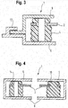
- Fig. 3 shows a further preferred embodiment of a compressor holder 1, wherein the base module 6 forms a tab 12 of the support structure 5, wherein in the tab 12 of the hold-8 can engage.
- a damping unit 4 can be positioned, wherein the damping unit 4 is connected to the compressor housing 2. In an operating state, the damping unit 4 is spaced from the hold-down 8, which is connected by means of the tab 12 with the base module 6.
- Fig. 4 shows a further embodiment of the compressor holder 1, wherein the compressor housing 2 is connected to a damping unit as a hollow body 14 and a damping unit as a solid body 18.
- the retaining structures 5 surround both the damping unit as a hollow body 14 and the damping unit as a solid 18 of at least two sides.
- Fig. 5 shows a schematic plan view of a compressor holder 1 with a compressor housing 2, which has three damping units 4. These damping units are each connected to a support structure 5, such as by means of a hold-8 for each damping unit. 4
- Fig. 6 shows a schematic plan view of a compressor holder 1 with a hold-8, which secures a plurality of damping units 4.
- the damping units 4 are connected to the compressor housing 2.
- the hold-down device 8 can be stationarily positioned with the base module 6, for example by means of a screw connection with screws 16 which are introduced from above into corresponding holes in the hold-down 8 during assembly.
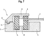
- Fig. 7 shows a schematic section through a compressor mount 1.
- the support structure 5 of the base module 6 is formed such that the support structure 5 has a characteristic 20.
- This expression on the holding structure 20 can engage in a bore of the damping unit 4 as a hollow body 14.
- the holding structure 5 has a bore 24 into which a shape on the hold-22 can engage.
- the hold-down 8 also has a further characteristic 22, which can engage in the upper side of the damping unit 4. In an operating state, the damping unit 4 is spaced from the hold-down 8, so that no vibrations or vibrations can be transmitted to the hold-down on the top of the damping unit.
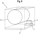
- Fig. 8 shows a schematic view of a household appliance 30 with a laundry drum 32.
- a compressor holder 1 is attached, which defines a compressor housing 2.
- Fig. 9 shows a schematic sectional view of a compressor holder 1 according to an eighth embodiment.
- the compressor holder 1 has a compressor housing 2, which is connected by means of damping units 4 with a base module 6 vibration-damped.
- the damping units 4 are positively inserted in a recess 26 of the compressor housing 2.
- the recess 26 is inserted in each case in one arm of the compressor housing 2.
- the damping units 4 are as a hollow body 14th or executed with a centered bore 28. In this way, the damping units 4 can be placed in designed as a pin 21 forms 20 and stationary on the base module 6 are positioned.
- the damping units 4 are inserted into receiving sections 29 of the base module 6.
- the receiving portions 29 each have a bearing surface 3, which has a damping units 4 corresponding shape.
- the bearing surfaces 3 are circular.
- the support surfaces 3 are bounded laterally by a bulge or a riser 34.
- the web 34 surrounds the damping units 4 in the inserted state at least partially and limits a maximum deformation of the damping units. 4
- the compressor housing 2 has a sheet metal edge 36, which in an installed state points in the direction of the base module 6.
- the base module 6 has a recess 40 which extends in accordance with the sheet metal edge 36.
- the recess 40 may extend between the receiving portions 29.
- the base module 6 is largely equidistant from the underside of the compressor 2.
- the base module 6 may be specifically adapted to a particular type of compressor or a compressor model.
- a distance h 2 between the compressor housing 2 and the base module 6 and the recess 40 are designed such that the compressor 2 can impact on the base module 6 in a contact by vibration surface.
- a distance h1 to the compressor 2 between the sheet edge 36 and the recess 40 is greater than the distance h2 between the compressor housing 2 and the rest of the base module 6, so that the contact between the sheet edge 36 and the base module 6 is avoided.
- the distance h2 can be adjusted in particular between the compressor housing 2 or the compressor and a reinforcing structure 42 of the base module 6.
- the recesses follow circumferentially a triangular shaped compressor housing 2, wherein the distance h1 is almost constant everywhere. This prevents contact between the thin sheet edges 36 in all directions.
- Fig. 10 shows a base module 6 according to one embodiment.
- a base module 6 adapted to the triangular shaped compressor housing 2 is illustrated.
- the recesses 40 connect the receiving portions 29 together to form a triangular base.
- a reinforcing structure 42 is introduced in the middle of the base module 6, .
- the reinforcing structure 42 and the base module 6 may consist of a plastic.
- the base module 6 with the bolts 21 and the reinforcing structure 42 is made in one piece.
- the reinforcing structure 42 of the base module 6 is formed according to the embodiment by radially arranged to the compressor 2 ribs to optimally derive possible loads.
- the webs 34 are formed here by recessed introduced receiving portions 29 and provide circumferential support function for damping units used. 4
- the shapes 20 formed as bolts 21 may have a height corresponding to the damping units 4. Furthermore, the bolts 21 can taper conically with increasing height.
Landscapes
- Engineering & Computer Science (AREA)
- Textile Engineering (AREA)
- Vibration Prevention Devices (AREA)
- Compressor (AREA)
Applications Claiming Priority (1)
| Application Number | Priority Date | Filing Date | Title |
|---|---|---|---|
| DE102018207641.3A DE102018207641A1 (de) | 2018-05-16 | 2018-05-16 | Kompressorhalterung und Verfahren zur Montage einer Kompressorhalterung |
Publications (2)
| Publication Number | Publication Date |
|---|---|
| EP3569952A1 true EP3569952A1 (fr) | 2019-11-20 |
| EP3569952B1 EP3569952B1 (fr) | 2021-02-17 |
Family
ID=66542032
Family Applications (1)
| Application Number | Title | Priority Date | Filing Date |
|---|---|---|---|
| EP19174067.9A Not-in-force EP3569952B1 (fr) | 2018-05-16 | 2019-05-13 | Module de base permettant de recevoir un compresseur et appareil électroménager |
Country Status (2)
| Country | Link |
|---|---|
| EP (1) | EP3569952B1 (fr) |
| DE (1) | DE102018207641A1 (fr) |
Citations (3)
| Publication number | Priority date | Publication date | Assignee | Title |
|---|---|---|---|---|
| EP2743394A1 (fr) * | 2012-12-14 | 2014-06-18 | Electrolux Home Products Corporation N.V. | Appareil de traitement de linge à pompe thermique |
| WO2016162160A1 (fr) * | 2015-04-07 | 2016-10-13 | BSH Hausgeräte GmbH | Amortissement de vibrations d'un entraînement d'une pompe à chaleur d'un appareil domestique |
| DE102016100932A1 (de) * | 2016-01-20 | 2017-07-20 | Miele & Cie. Kg | Bodenmodul und Bodenmodulvorrichtung für einen Wärmepumpentrockner, Wärmepumpentrockner und Verfahren zum Herstellen einer Bodenmodulvorrichtung |
Family Cites Families (8)
| Publication number | Priority date | Publication date | Assignee | Title |
|---|---|---|---|---|
| DE1067453B (de) * | 1959-10-22 | LICENTIA Patent Verwaltungs-GmbH, Hamburg | Elastische Lagerung fur Motorkompressorkapseln von Kleinkalte maschinen | |
| DE1020996B (de) * | 1957-12-19 | G. Bauknecht G.M.B.H., Elektrotechnische Fabriken, Stuttgart | Gummikissenlager für Kleinkältemaschinen-Kompressoren in Haushartkühlschränken | |
| IT215720Z2 (it) * | 1989-02-21 | 1990-10-26 | Eurodomestici Ind Riunite | Dispositivo per il fissaggio di un compressore particolarmente a un mobile di un frigorifero, congelatore o similare. |
| JP2006329506A (ja) * | 2005-05-25 | 2006-12-07 | Sharp Corp | 冷蔵庫の圧縮機取り付け構造,冷蔵庫 |
| DE202006015443U1 (de) * | 2006-10-09 | 2007-01-11 | Truma Gerätetechnik GmbH & Co. KG | Gehäuse für Klimagerät mit Verdichter |
| DE102009027885A1 (de) * | 2009-07-21 | 2011-01-27 | BSH Bosch und Siemens Hausgeräte GmbH | Kältegerät, insbesondere Haushaltskältegerät mit einer Befestigungsanordnung für einen Verdichter |
| DE102014206718A1 (de) * | 2014-04-08 | 2015-10-08 | BSH Hausgeräte GmbH | Haushaltsgerät |
| DE102016206525A1 (de) * | 2016-04-19 | 2017-10-19 | BSH Hausgeräte GmbH | Wäschetrocknungsgerät mit Wärmepumpe und zugehörigem Antrieb |
-
2018
- 2018-05-16 DE DE102018207641.3A patent/DE102018207641A1/de not_active Withdrawn
-
2019
- 2019-05-13 EP EP19174067.9A patent/EP3569952B1/fr not_active Not-in-force
Patent Citations (3)
| Publication number | Priority date | Publication date | Assignee | Title |
|---|---|---|---|---|
| EP2743394A1 (fr) * | 2012-12-14 | 2014-06-18 | Electrolux Home Products Corporation N.V. | Appareil de traitement de linge à pompe thermique |
| WO2016162160A1 (fr) * | 2015-04-07 | 2016-10-13 | BSH Hausgeräte GmbH | Amortissement de vibrations d'un entraînement d'une pompe à chaleur d'un appareil domestique |
| DE102016100932A1 (de) * | 2016-01-20 | 2017-07-20 | Miele & Cie. Kg | Bodenmodul und Bodenmodulvorrichtung für einen Wärmepumpentrockner, Wärmepumpentrockner und Verfahren zum Herstellen einer Bodenmodulvorrichtung |
Also Published As
| Publication number | Publication date |
|---|---|
| DE102018207641A1 (de) | 2019-11-21 |
| EP3569952B1 (fr) | 2021-02-17 |
Similar Documents
| Publication | Publication Date | Title |
|---|---|---|
| EP3158851B1 (fr) | Courroie crantée, en particulier pour machines agricoles | |
| EP3535822B1 (fr) | Armoire électrique avec panneau de montage | |
| EP3286042B1 (fr) | Ensemble volant, module de coussin gonflable et un corps du volant | |
| EP2118356B1 (fr) | Amortisseur à friction destiné notamment à des lave-linge à tambour | |
| DE102012019443B4 (de) | Lagerelement an einem Fahrzeug, Verfahren zur Verwendung eines derartigen Lagerelements, Montageträger mit einem derartigen Lagerelement und Fahrzeug dazu | |
| DE102017006163B4 (de) | Lagerelement und Lager | |
| EP3498504A1 (fr) | Bras de suspension à ressort pour une suspension de roue d'un véhicule automobile | |
| EP2162589A1 (fr) | Dispositif d'amortissement et système de fixation | |
| EP3569952A1 (fr) | Module de base permettant de recevoir un compresseur et appareil électroménager | |
| DE102008029768B4 (de) | Kleiderbügel | |
| DE102018208196B4 (de) | Pufferelement für eine Frontklappe oder Heckklappe eines Kraftfahrzeuges sowie Anordnung eines solchen Pufferelements an einem Karosserieelement eines Kraftfahrzeuges | |
| DE10311196A1 (de) | Aufhängung, insbesondere für eine Abgasanlage eines Kraftfahrzeuges | |
| EP1741820B1 (fr) | Machine à laver avec un dispositif de fixation pour le transport | |
| WO2016162160A1 (fr) | Amortissement de vibrations d'un entraînement d'une pompe à chaleur d'un appareil domestique | |
| DE102019008388A1 (de) | Lagersystem und Verfahren zur Lagerung eines Fahrzeugbauteils | |
| DE10147514B4 (de) | Elastisches Pendellager | |
| DE102004001286B4 (de) | Vorrichtung zur Halterung eines Bauteils an einer Karosserie | |
| EP3330110A1 (fr) | Support de palier permettant de fixer un bras oscillant longitudinal à essieux rigides pourvu de composant d'appui influençant le cas de charge de fonctionnement | |
| DE102021114999B3 (de) | Schwingungstilger mit einer über stirnseitig eingepresste Federbaugruppen elastisch abgestützten Tilgermasse | |
| EP3827175B1 (fr) | Élément structural | |
| DE102018130419B4 (de) | Untere Stoßfängerabstützung für ein Kraftfahrzeug | |
| EP1808316B1 (fr) | Support pour un amortisseur de vibrations | |
| DE9206506U1 (de) | Einrichtung zur Fixierung des schwingenden Systems einer Haushaltsmaschine | |
| EP1008478A2 (fr) | Dispositif d'amortissement, notament élément caoutchouc-métal | |
| DE102017115206B4 (de) | Unterbodenverkleidung für ein Kraftfahrzeug |
Legal Events
| Date | Code | Title | Description |
|---|---|---|---|
| PUAI | Public reference made under article 153(3) epc to a published international application that has entered the european phase |
Free format text: ORIGINAL CODE: 0009012 |
|
| STAA | Information on the status of an ep patent application or granted ep patent |
Free format text: STATUS: THE APPLICATION HAS BEEN PUBLISHED |
|
| AK | Designated contracting states |
Kind code of ref document: A1 Designated state(s): AL AT BE BG CH CY CZ DE DK EE ES FI FR GB GR HR HU IE IS IT LI LT LU LV MC MK MT NL NO PL PT RO RS SE SI SK SM TR |
|
| AX | Request for extension of the european patent |
Extension state: BA ME |
|
| STAA | Information on the status of an ep patent application or granted ep patent |
Free format text: STATUS: REQUEST FOR EXAMINATION WAS MADE |
|
| 17P | Request for examination filed |
Effective date: 20200520 |
|
| RBV | Designated contracting states (corrected) |
Designated state(s): AL AT BE BG CH CY CZ DE DK EE ES FI FR GB GR HR HU IE IS IT LI LT LU LV MC MK MT NL NO PL PT RO RS SE SI SK SM TR |
|
| REG | Reference to a national code |
Ref country code: DE Ref legal event code: R079 Ref document number: 502019000800 Country of ref document: DE Free format text: PREVIOUS MAIN CLASS: F25B0031000000 Ipc: D06F0058200000 |
|
| RIC1 | Information provided on ipc code assigned before grant |
Ipc: D06F 58/20 20060101AFI20200812BHEP |
|
| GRAP | Despatch of communication of intention to grant a patent |
Free format text: ORIGINAL CODE: EPIDOSNIGR1 |
|
| STAA | Information on the status of an ep patent application or granted ep patent |
Free format text: STATUS: GRANT OF PATENT IS INTENDED |
|
| INTG | Intention to grant announced |
Effective date: 20200921 |
|
| GRAS | Grant fee paid |
Free format text: ORIGINAL CODE: EPIDOSNIGR3 |
|
| GRAA | (expected) grant |
Free format text: ORIGINAL CODE: 0009210 |
|
| STAA | Information on the status of an ep patent application or granted ep patent |
Free format text: STATUS: THE PATENT HAS BEEN GRANTED |
|
| AK | Designated contracting states |
Kind code of ref document: B1 Designated state(s): AL AT BE BG CH CY CZ DE DK EE ES FI FR GB GR HR HU IE IS IT LI LT LU LV MC MK MT NL NO PL PT RO RS SE SI SK SM TR |
|
| REG | Reference to a national code |
Ref country code: GB Ref legal event code: FG4D Free format text: NOT ENGLISH |
|
| REG | Reference to a national code |
Ref country code: CH Ref legal event code: EP |
|
| REG | Reference to a national code |
Ref country code: DE Ref legal event code: R096 Ref document number: 502019000800 Country of ref document: DE |
|
| REG | Reference to a national code |
Ref country code: AT Ref legal event code: REF Ref document number: 1361607 Country of ref document: AT Kind code of ref document: T Effective date: 20210315 |
|
| REG | Reference to a national code |
Ref country code: IE Ref legal event code: FG4D Free format text: LANGUAGE OF EP DOCUMENT: GERMAN |
|
| REG | Reference to a national code |
Ref country code: LT Ref legal event code: MG9D |
|
| REG | Reference to a national code |
Ref country code: NL Ref legal event code: MP Effective date: 20210217 |
|
| PG25 | Lapsed in a contracting state [announced via postgrant information from national office to epo] |
Ref country code: BG Free format text: LAPSE BECAUSE OF FAILURE TO SUBMIT A TRANSLATION OF THE DESCRIPTION OR TO PAY THE FEE WITHIN THE PRESCRIBED TIME-LIMIT Effective date: 20210517 Ref country code: HR Free format text: LAPSE BECAUSE OF FAILURE TO SUBMIT A TRANSLATION OF THE DESCRIPTION OR TO PAY THE FEE WITHIN THE PRESCRIBED TIME-LIMIT Effective date: 20210217 Ref country code: GR Free format text: LAPSE BECAUSE OF FAILURE TO SUBMIT A TRANSLATION OF THE DESCRIPTION OR TO PAY THE FEE WITHIN THE PRESCRIBED TIME-LIMIT Effective date: 20210518 Ref country code: FI Free format text: LAPSE BECAUSE OF FAILURE TO SUBMIT A TRANSLATION OF THE DESCRIPTION OR TO PAY THE FEE WITHIN THE PRESCRIBED TIME-LIMIT Effective date: 20210217 Ref country code: LT Free format text: LAPSE BECAUSE OF FAILURE TO SUBMIT A TRANSLATION OF THE DESCRIPTION OR TO PAY THE FEE WITHIN THE PRESCRIBED TIME-LIMIT Effective date: 20210217 Ref country code: NO Free format text: LAPSE BECAUSE OF FAILURE TO SUBMIT A TRANSLATION OF THE DESCRIPTION OR TO PAY THE FEE WITHIN THE PRESCRIBED TIME-LIMIT Effective date: 20210517 Ref country code: PT Free format text: LAPSE BECAUSE OF FAILURE TO SUBMIT A TRANSLATION OF THE DESCRIPTION OR TO PAY THE FEE WITHIN THE PRESCRIBED TIME-LIMIT Effective date: 20210617 |
|
| PG25 | Lapsed in a contracting state [announced via postgrant information from national office to epo] |
Ref country code: PL Free format text: LAPSE BECAUSE OF FAILURE TO SUBMIT A TRANSLATION OF THE DESCRIPTION OR TO PAY THE FEE WITHIN THE PRESCRIBED TIME-LIMIT Effective date: 20210217 Ref country code: NL Free format text: LAPSE BECAUSE OF FAILURE TO SUBMIT A TRANSLATION OF THE DESCRIPTION OR TO PAY THE FEE WITHIN THE PRESCRIBED TIME-LIMIT Effective date: 20210217 Ref country code: LV Free format text: LAPSE BECAUSE OF FAILURE TO SUBMIT A TRANSLATION OF THE DESCRIPTION OR TO PAY THE FEE WITHIN THE PRESCRIBED TIME-LIMIT Effective date: 20210217 Ref country code: RS Free format text: LAPSE BECAUSE OF FAILURE TO SUBMIT A TRANSLATION OF THE DESCRIPTION OR TO PAY THE FEE WITHIN THE PRESCRIBED TIME-LIMIT Effective date: 20210217 Ref country code: SE Free format text: LAPSE BECAUSE OF FAILURE TO SUBMIT A TRANSLATION OF THE DESCRIPTION OR TO PAY THE FEE WITHIN THE PRESCRIBED TIME-LIMIT Effective date: 20210217 |
|
| PG25 | Lapsed in a contracting state [announced via postgrant information from national office to epo] |
Ref country code: IS Free format text: LAPSE BECAUSE OF FAILURE TO SUBMIT A TRANSLATION OF THE DESCRIPTION OR TO PAY THE FEE WITHIN THE PRESCRIBED TIME-LIMIT Effective date: 20210617 |
|
| PG25 | Lapsed in a contracting state [announced via postgrant information from national office to epo] |
Ref country code: SM Free format text: LAPSE BECAUSE OF FAILURE TO SUBMIT A TRANSLATION OF THE DESCRIPTION OR TO PAY THE FEE WITHIN THE PRESCRIBED TIME-LIMIT Effective date: 20210217 Ref country code: CZ Free format text: LAPSE BECAUSE OF FAILURE TO SUBMIT A TRANSLATION OF THE DESCRIPTION OR TO PAY THE FEE WITHIN THE PRESCRIBED TIME-LIMIT Effective date: 20210217 Ref country code: EE Free format text: LAPSE BECAUSE OF FAILURE TO SUBMIT A TRANSLATION OF THE DESCRIPTION OR TO PAY THE FEE WITHIN THE PRESCRIBED TIME-LIMIT Effective date: 20210217 |
|
| REG | Reference to a national code |
Ref country code: DE Ref legal event code: R097 Ref document number: 502019000800 Country of ref document: DE |
|
| PG25 | Lapsed in a contracting state [announced via postgrant information from national office to epo] |
Ref country code: DK Free format text: LAPSE BECAUSE OF FAILURE TO SUBMIT A TRANSLATION OF THE DESCRIPTION OR TO PAY THE FEE WITHIN THE PRESCRIBED TIME-LIMIT Effective date: 20210217 Ref country code: RO Free format text: LAPSE BECAUSE OF FAILURE TO SUBMIT A TRANSLATION OF THE DESCRIPTION OR TO PAY THE FEE WITHIN THE PRESCRIBED TIME-LIMIT Effective date: 20210217 Ref country code: SK Free format text: LAPSE BECAUSE OF FAILURE TO SUBMIT A TRANSLATION OF THE DESCRIPTION OR TO PAY THE FEE WITHIN THE PRESCRIBED TIME-LIMIT Effective date: 20210217 |
|
| PLBE | No opposition filed within time limit |
Free format text: ORIGINAL CODE: 0009261 |
|
| STAA | Information on the status of an ep patent application or granted ep patent |
Free format text: STATUS: NO OPPOSITION FILED WITHIN TIME LIMIT |
|
| 26N | No opposition filed |
Effective date: 20211118 |
|
| PG25 | Lapsed in a contracting state [announced via postgrant information from national office to epo] |
Ref country code: ES Free format text: LAPSE BECAUSE OF FAILURE TO SUBMIT A TRANSLATION OF THE DESCRIPTION OR TO PAY THE FEE WITHIN THE PRESCRIBED TIME-LIMIT Effective date: 20210217 Ref country code: MC Free format text: LAPSE BECAUSE OF FAILURE TO SUBMIT A TRANSLATION OF THE DESCRIPTION OR TO PAY THE FEE WITHIN THE PRESCRIBED TIME-LIMIT Effective date: 20210217 Ref country code: AL Free format text: LAPSE BECAUSE OF FAILURE TO SUBMIT A TRANSLATION OF THE DESCRIPTION OR TO PAY THE FEE WITHIN THE PRESCRIBED TIME-LIMIT Effective date: 20210217 Ref country code: LU Free format text: LAPSE BECAUSE OF NON-PAYMENT OF DUE FEES Effective date: 20210513 |
|
| REG | Reference to a national code |
Ref country code: BE Ref legal event code: MM Effective date: 20210531 |
|
| PG25 | Lapsed in a contracting state [announced via postgrant information from national office to epo] |
Ref country code: SI Free format text: LAPSE BECAUSE OF FAILURE TO SUBMIT A TRANSLATION OF THE DESCRIPTION OR TO PAY THE FEE WITHIN THE PRESCRIBED TIME-LIMIT Effective date: 20210217 |
|
| PG25 | Lapsed in a contracting state [announced via postgrant information from national office to epo] |
Ref country code: IT Free format text: LAPSE BECAUSE OF FAILURE TO SUBMIT A TRANSLATION OF THE DESCRIPTION OR TO PAY THE FEE WITHIN THE PRESCRIBED TIME-LIMIT Effective date: 20210217 Ref country code: IE Free format text: LAPSE BECAUSE OF NON-PAYMENT OF DUE FEES Effective date: 20210513 |
|
| PG25 | Lapsed in a contracting state [announced via postgrant information from national office to epo] |
Ref country code: IS Free format text: LAPSE BECAUSE OF FAILURE TO SUBMIT A TRANSLATION OF THE DESCRIPTION OR TO PAY THE FEE WITHIN THE PRESCRIBED TIME-LIMIT Effective date: 20210617 Ref country code: FR Free format text: LAPSE BECAUSE OF NON-PAYMENT OF DUE FEES Effective date: 20210531 |
|
| PG25 | Lapsed in a contracting state [announced via postgrant information from national office to epo] |
Ref country code: BE Free format text: LAPSE BECAUSE OF NON-PAYMENT OF DUE FEES Effective date: 20210531 |
|
| REG | Reference to a national code |
Ref country code: CH Ref legal event code: PL |
|
| PG25 | Lapsed in a contracting state [announced via postgrant information from national office to epo] |
Ref country code: LI Free format text: LAPSE BECAUSE OF NON-PAYMENT OF DUE FEES Effective date: 20220531 Ref country code: CH Free format text: LAPSE BECAUSE OF NON-PAYMENT OF DUE FEES Effective date: 20220531 |
|
| REG | Reference to a national code |
Ref country code: DE Ref legal event code: R084 Ref document number: 502019000800 Country of ref document: DE |
|
| REG | Reference to a national code |
Ref country code: DE Ref legal event code: R085 Ref document number: 502019000800 Country of ref document: DE |
|
| PG25 | Lapsed in a contracting state [announced via postgrant information from national office to epo] |
Ref country code: CY Free format text: LAPSE BECAUSE OF FAILURE TO SUBMIT A TRANSLATION OF THE DESCRIPTION OR TO PAY THE FEE WITHIN THE PRESCRIBED TIME-LIMIT Effective date: 20210217 |
|
| PG25 | Lapsed in a contracting state [announced via postgrant information from national office to epo] |
Ref country code: HU Free format text: LAPSE BECAUSE OF FAILURE TO SUBMIT A TRANSLATION OF THE DESCRIPTION OR TO PAY THE FEE WITHIN THE PRESCRIBED TIME-LIMIT; INVALID AB INITIO Effective date: 20190513 |
|
| PGFP | Annual fee paid to national office [announced via postgrant information from national office to epo] |
Ref country code: DE Payment date: 20230531 Year of fee payment: 5 |
|
| GBPC | Gb: european patent ceased through non-payment of renewal fee |
Effective date: 20230513 |
|
| PG25 | Lapsed in a contracting state [announced via postgrant information from national office to epo] |
Ref country code: MK Free format text: LAPSE BECAUSE OF FAILURE TO SUBMIT A TRANSLATION OF THE DESCRIPTION OR TO PAY THE FEE WITHIN THE PRESCRIBED TIME-LIMIT Effective date: 20210217 Ref country code: GB Free format text: LAPSE BECAUSE OF NON-PAYMENT OF DUE FEES Effective date: 20230513 |
|
| PG25 | Lapsed in a contracting state [announced via postgrant information from national office to epo] |
Ref country code: MT Free format text: LAPSE BECAUSE OF FAILURE TO SUBMIT A TRANSLATION OF THE DESCRIPTION OR TO PAY THE FEE WITHIN THE PRESCRIBED TIME-LIMIT Effective date: 20210217 |
|
| REG | Reference to a national code |
Ref country code: DE Ref legal event code: R119 Ref document number: 502019000800 Country of ref document: DE |
|
| PG25 | Lapsed in a contracting state [announced via postgrant information from national office to epo] |
Ref country code: DE Free format text: LAPSE BECAUSE OF NON-PAYMENT OF DUE FEES Effective date: 20241203 |
|
| REG | Reference to a national code |
Ref country code: AT Ref legal event code: MM01 Ref document number: 1361607 Country of ref document: AT Kind code of ref document: T Effective date: 20240513 |
|
| PG25 | Lapsed in a contracting state [announced via postgrant information from national office to epo] |
Ref country code: AT Free format text: LAPSE BECAUSE OF NON-PAYMENT OF DUE FEES Effective date: 20240513 |
|
| PG25 | Lapsed in a contracting state [announced via postgrant information from national office to epo] |
Ref country code: TR Free format text: LAPSE BECAUSE OF FAILURE TO SUBMIT A TRANSLATION OF THE DESCRIPTION OR TO PAY THE FEE WITHIN THE PRESCRIBED TIME-LIMIT Effective date: 20210217 |
|
| PGFP | Annual fee paid to national office [announced via postgrant information from national office to epo] |
Ref country code: AT Payment date: 20260410 Year of fee payment: 5 |