EP3570017A2 - Préparation d'une mesure de distillation - Google Patents
Préparation d'une mesure de distillation Download PDFInfo
- Publication number
- EP3570017A2 EP3570017A2 EP19174595.9A EP19174595A EP3570017A2 EP 3570017 A2 EP3570017 A2 EP 3570017A2 EP 19174595 A EP19174595 A EP 19174595A EP 3570017 A2 EP3570017 A2 EP 3570017A2
- Authority
- EP
- European Patent Office
- Prior art keywords
- container
- perforated plate
- heater
- liquid
- standardized
- Prior art date
- Legal status (The legal status is an assumption and is not a legal conclusion. Google has not performed a legal analysis and makes no representation as to the accuracy of the status listed.)
- Granted
Links
Images
Classifications
-
- G—PHYSICS
- G01—MEASURING; TESTING
- G01N—INVESTIGATING OR ANALYSING MATERIALS BY DETERMINING THEIR CHEMICAL OR PHYSICAL PROPERTIES
- G01N25/00—Investigating or analyzing materials by the use of thermal means
- G01N25/02—Investigating or analyzing materials by the use of thermal means by investigating changes of state or changes of phase; by investigating sintering
- G01N25/08—Investigating or analyzing materials by the use of thermal means by investigating changes of state or changes of phase; by investigating sintering of boiling point
- G01N25/10—Analysis by measuring change of boiling point
-
- G—PHYSICS
- G01—MEASURING; TESTING
- G01N—INVESTIGATING OR ANALYSING MATERIALS BY DETERMINING THEIR CHEMICAL OR PHYSICAL PROPERTIES
- G01N25/00—Investigating or analyzing materials by the use of thermal means
- G01N25/14—Investigating or analyzing materials by the use of thermal means by using distillation, extraction, sublimation, condensation, freezing, or crystallisation
-
- B—PERFORMING OPERATIONS; TRANSPORTING
- B01—PHYSICAL OR CHEMICAL PROCESSES OR APPARATUS IN GENERAL
- B01D—SEPARATION
- B01D19/00—Degasification of liquids
- B01D19/02—Foam dispersion or prevention
- B01D19/04—Foam dispersion or prevention by addition of chemical substances
- B01D19/0404—Foam dispersion or prevention by addition of chemical substances characterised by the nature of the chemical substance
-
- B—PERFORMING OPERATIONS; TRANSPORTING
- B01—PHYSICAL OR CHEMICAL PROCESSES OR APPARATUS IN GENERAL
- B01D—SEPARATION
- B01D3/00—Distillation or related exchange processes in which liquids are contacted with gaseous media, e.g. stripping
-
- B—PERFORMING OPERATIONS; TRANSPORTING
- B01—PHYSICAL OR CHEMICAL PROCESSES OR APPARATUS IN GENERAL
- B01L—CHEMICAL OR PHYSICAL LABORATORY APPARATUS FOR GENERAL USE
- B01L7/00—Heating or cooling apparatus; Heat insulating devices
-
- B—PERFORMING OPERATIONS; TRANSPORTING
- B01—PHYSICAL OR CHEMICAL PROCESSES OR APPARATUS IN GENERAL
- B01L—CHEMICAL OR PHYSICAL LABORATORY APPARATUS FOR GENERAL USE
- B01L9/00—Supporting devices; Holding devices
- B01L9/04—Retort stands; Retort clamps
-
- G—PHYSICS
- G01—MEASURING; TESTING
- G01N—INVESTIGATING OR ANALYSING MATERIALS BY DETERMINING THEIR CHEMICAL OR PHYSICAL PROPERTIES
- G01N25/00—Investigating or analyzing materials by the use of thermal means
- G01N25/02—Investigating or analyzing materials by the use of thermal means by investigating changes of state or changes of phase; by investigating sintering
- G01N25/08—Investigating or analyzing materials by the use of thermal means by investigating changes of state or changes of phase; by investigating sintering of boiling point
-
- G—PHYSICS
- G01—MEASURING; TESTING
- G01N—INVESTIGATING OR ANALYSING MATERIALS BY DETERMINING THEIR CHEMICAL OR PHYSICAL PROPERTIES
- G01N25/00—Investigating or analyzing materials by the use of thermal means
- G01N25/14—Investigating or analyzing materials by the use of thermal means by using distillation, extraction, sublimation, condensation, freezing, or crystallisation
- G01N25/142—Investigating or analyzing materials by the use of thermal means by using distillation, extraction, sublimation, condensation, freezing, or crystallisation by condensation
-
- B—PERFORMING OPERATIONS; TRANSPORTING
- B01—PHYSICAL OR CHEMICAL PROCESSES OR APPARATUS IN GENERAL
- B01D—SEPARATION
- B01D3/00—Distillation or related exchange processes in which liquids are contacted with gaseous media, e.g. stripping
- B01D3/42—Regulation; Control
-
- B—PERFORMING OPERATIONS; TRANSPORTING
- B01—PHYSICAL OR CHEMICAL PROCESSES OR APPARATUS IN GENERAL
- B01L—CHEMICAL OR PHYSICAL LABORATORY APPARATUS FOR GENERAL USE
- B01L3/00—Containers or dishes for laboratory use, e.g. laboratory glassware; Droppers
- B01L3/08—Flasks
-
- B—PERFORMING OPERATIONS; TRANSPORTING
- B01—PHYSICAL OR CHEMICAL PROCESSES OR APPARATUS IN GENERAL
- B01L—CHEMICAL OR PHYSICAL LABORATORY APPARATUS FOR GENERAL USE
- B01L9/00—Supporting devices; Holding devices
-
- B—PERFORMING OPERATIONS; TRANSPORTING
- B01—PHYSICAL OR CHEMICAL PROCESSES OR APPARATUS IN GENERAL
- B01L—CHEMICAL OR PHYSICAL LABORATORY APPARATUS FOR GENERAL USE
- B01L9/00—Supporting devices; Holding devices
- B01L9/02—Laboratory benches or tables; Fittings therefor
Definitions
- the present invention relates to a device for preparing a distillation measurement of a liquid, further relates to a liquid analysis system, in particular automatic distillation unit for determining evaporation properties of a liquid according to at least one standardized test and still further relates to a method for preparing a distillation measurement of a liquid.
- perforated plates or insulating plates differ, inter alia, in the diameter of the hole in the center of the plate, rests on the edge during the standardized measurement or during the standardized test of the round bottomed flask. In this case, the perforated plate sits on the heater, which is brought from below to the piston until the perforated plate seals the piston from the bottom tight.
- EP 1 967 269 B1 discloses an automatic positioning device having a heating chamber opposite a still, comprising a stationary stator, a heating chamber with a heating element, a set of stills with plugs and thermometers incorporated therein, a set of insulating plates, and means for controlling the heater.
- a slide is connected to the heating chamber by a constant force spring to to move the heating chamber between a rest position and a working position.
- manual actuating means for moving the carriage and locking means for fixing the working position are provided.
- EP 1 967 848 B1 discloses a decoding apparatus of insulating plates for a standardized distillation apparatus, wherein decoating holes are formed in an insulating plate and distributed on a surface of the decoder based on a model specific to the surface.
- a set of sensors are associated with the respective decode holes and the sensors emit detection signals representing the insulation plates to verify that an insulation plate meeting a predetermined test standard is interposed between a heating element and a distillation flask.
- the perforated plate is selected by a user before starting a standardized test. This can make a mistake by the user selects a wrong hole plate and touches down on the heater. If a wrong perforated plate is used, the test can not be carried out without errors, in particular, it can not be carried out in accordance with the standard or the standard. The test must then be stopped, the correct perforated plate must be selected and placed on the heater and the test must be started again. This increases time and costs.
- a device for preparing a distillation measurement of a liquid comprising: a heater to which a perforated plate selected from a group of standardized perforated plates can be placed and for heating a container containing the liquid placed on the perforated plate for passing a standardized test for determining evaporation properties of the liquid is formed; a, in particular electrical, traversing system, which is designed to move the heating (for example vertically upwards) and to interrupt another method of the heating system, if a pressing force of the perforated plate placed on the heating against the container reaches a threshold value.
- the present invention is in the field of Automatic (or Atmospheric) Distillation Units (ADU), which can be used to determine the boiling behavior of liquids, particularly petroleum products or solvents, according to various standards (e.g., ASTM D86).
- ADU Automatic (or Atmospheric) Distillation Units
- the distillation behavior of the liquid is u.a. Characterized by a temperature measurement.
- the distillation measurement may comprise a standardized test according to a standard, eg ASTM standard or ISO standard.
- the distillation curve can be obtained by plotting the temperature against the relative recovery volume in the receiving cylinder. From the distillation curve, e.g. The boiling range of the sample can be derived as the difference between the maximum temperature and the minimum temperature.
- embodiments of the present invention are suitable for performing standard tests for the distillation of petroleum products, such as ASTM D86 (Groups 0 to 4), ISO3405, IP123, BS2000-123, each in the version valid on the filing date.
- Embodiments of the present invention are also suitable for conducting standard tests for the distillation of solvents, such as ASTM D1078, IP95, BS2000-195, ASTM D850. As results of carrying out the tests, a respective distillation curve of the tested sample, as well as e.g. the drying point can be obtained.
- the above tests are feasible at least on the respective versions of the standard tests valid on the filing date.
- embodiments of the present invention may support a standardized assay of a sample having a boiling range between, for example, 20 ° C and 400 ° C.
- the standards ASTM D86, ASTM D850, ASTM D1078 can be supported, as well as ISO 3405, IP 123, IP 195, all in the version valid on the filing date.
- the specifications for these standard tests can be obtained from ASTM (eg www.ASTM.org ).
- a steam temperature range of 0 ° C to 450 ° C, a condenser temperature range of 0 ° C to 80 ° C and a chamber temperature range of 0 ° to 50 ° can be promoted.
- an atmospheric pressure sensor may be included in embodiments, which makes it possible to automatically correct the results to a standard pressure.
- embodiments of the present invention are designed for the characterization of petroleum products, in particular different from seawater desalination plants, drinking water treatment plants, wastewater purification plants, chemical plants for the treatment of hydrocarbons, rotary evaporators, distillation plants for the processing of biological substances.
- embodiments of the present invention provide a standardized distillation apparatus, particularly an atmospheric pressure automatic distillation apparatus for liquid samples, in particular for samples of mineral oil products, the measurement of distillation parameters being performed according to a predefined test standard selected from a plurality of possible standards, some examples of which have been given above.
- a standardized distillation apparatus for measuring distillation parameters under reduced pressure or under vacuum may be provided.
- the perforated plate can be made of insulating material and have a central hole or a central recess, which is circular.
- the diameter of the circular recess in the perforated plate may be smaller than the diameter of a container, in particular a round-bottomed flask.
- the perforated plate can be reversibly connectable to the heater, such as by one or more terminals, a screw mechanism, magnetic elements or the like.
- the container in particular glass round-bottomed flask, can in particular, after placing the perforated plate on the heater, be placed on the perforated plate such that the edge of the circular recess contacts an outer surface, in particular a strip of a spherical surface, in order to achieve that a predetermined part of the Round piston, which is located below the plane of the perforated plate, is located in a predetermined position relative to heating elements of the heater.
- heating of the liquid within the container can be achieved according to one or more defined standards.
- the heater may include electrical heating elements.
- the liquid may in particular be a mineral oil product or a mixture of mineral oil products or, for example, crude oil.
- Other examples of liquids include solvents used in the paint industry to disperse pigments.
- the positioning system may in particular comprise electrical components, such as an electric motor, in particular a stepper motor, which is used as drive for the method of heating.
- the electric traversing system can automatically move the heating upwards until the edge of the perforated plate delimiting the circular opening makes circular contact with the round-bottomed piston and until the pressing force reaches the threshold value.
- a manual intervention of a user after starting the (electric) drive system need not be required.
- the apparatus may be configured to move the heating system toward the piston such that a test is then prepared according to at least one standard for determining evaporation characteristics of the liquid without further manual intervention of a user and then performed can.
- the travel system does not require manual intervention by a user to move the heater (up), i. to move upwards. This can prevent incorrect operation.
- the (in particular electrical) traversing system can be designed to heat the heating at a suitable speed, e.g. to move at a constant speed which avoids damage to components.
- the positioning system may also be designed, e.g. at a relatively large distance between the perforated plate and the piston, first to provide a relatively high travel speed, which is reduced with decreasing the distance between the perforated plate and the piston continuously or in steps. Thus both a quick preparation can be achieved without involving a risk of damage.
- the device may acoustically and / or optically display this non-compatibility. Furthermore, performing a standardized tests in such a case can be prevented by a corresponding activation of further components supporting this test in normal operation, such as the heating itself, temperature measuring system, evaluation system, display system, etc.
- a quick preparation of a standardized test can be achieved and when using faulty components, a warning can be displayed so that operating errors, in particular performing further test steps in a faulty manner, can be prevented.
- the positioning system comprises a movable carrier system on which the heater is mounted.
- the device can be designed to monitor and / or determine a variable indicative of a length and / or a position along a travel path of the carrier system, in particular the number of steps of a stepper motor.
- the carrier system is movable, in particular electrically movable, in particular vertically upwardly movable and in particular driven by an electric motor for movement.
- the support system may include an arm, a rod, a table, or a combination thereof to support, support, or support the heater, for example.
- the carrier system may comprise a plurality of components, for example a component which is in engagement with a drive motor (eg indirectly via a spindle) and a second component which supports or supports the heater.
- the first component and the second component need not be mechanically connected by a rigid connection, but may be connected, for example via an elastic connection, such as a spring, in particular coil spring, which can be used for force measurement.
- the pressing force can be measured, for example, based on a deformation of a spring, such as coil spring or, for example via piezoelectric elements.
- a spring such as coil spring or, for example via piezoelectric elements.
- the threshold value can correspond to a predetermined pressure force in accordance with a predetermined test standard.
- the travel can e.g. a linear, i. straight path, about exactly vertical upward.
- the travel can be defined by one or more rails and / or by a spindle driven by a motor.
- the pressing force may be a force in the vertical direction between the perforated plate and the piston or container.
- the container Before the carrier system is moved together with the heater and the perforated plate towards the (lower end) of the container, the container may be supported at one upper end by one or more holding elements (in fixed position), without the lower container region, in particular round glass flasks. to hold.
- the lower part of the container can thus be free of further support elements.
- a space below the container may be free, so that the heater can be brought together with the perforated plate safely from below to the container.
- the bracket at the upper portion of the container may be so strong that it can withstand the pressing force according to the threshold value.
- the indicative of the position of the travel of the carrier system size may for example be given in a unit length or in a number of revolutions of a stepping motor or represented by a voltage or the like.
- the position may be relative to a reference position, such as Starting position, defined by about a length in a unit length, such as millimeters, or by specifying a number of steps or revolutions, which were performed by a stepper motor or another electric motor.
- the indicative of the length along the travel path of the carrier system size can be determined for example by a difference of a reference position and a current position of the carrier system.
- the position of the carrier system may relate, for example, to the position of a particular component or a particular detail of the carrier system.
- the position of the carrier system can either be moved to a position of the first component, which is primarily by a motor, in particular an electric motor, or to a position of a second component, which is connected, for example via an elastic element elastically with the first component of the carrier system , Respectively.
- the device is designed to move the carrier system from an initial position, in particular a predetermined initial position, to an end position of the carrier system in which the pressure force reaches the threshold value, wherein the position associated with the starting position along the Travel indicative size has a first value and wherein the position indicative of the position along the travel path associated with the end position has a second value, wherein the device is adapted, the difference of the first value and the second value as indicative of the thereby traversed path length difference value to calculate.
- the end position of the carrier system can correspond to that state in which the perforated plate has moved completely up to the container, so that the edge of the hole of the perforated plate partially surrounds the container and contacts an outer wall in particular in a circular manner.
- the Contact pressure mediated according to the threshold in the end position is the Contact pressure mediated according to the threshold in the end position.
- the starting position may be any position during the entire travel previously traveled, in particular may be a predefined starting position. The starting position is lower than the end position.
- the (electrical) movement system is at least designed to move the heater upwards (together with the perforated plate).
- the positioning system can also be designed to move the heater downwards (together with the perforated plate), in particular to the starting position, in particular the starting position back.
- the speed of the return trip can initially be relatively low in order to slowly release the perforated plate from the container, which avoids its damage. Then the speed of the return trip can be increased without having to damage any other components.
- the speed during the return journey is substantially constant. However, it can e.g. be faster than the speed during startup.
- the difference value is thus indicative of a travel path length between the starting position and the end position.
- the difference value may be different when using different perforated plates, and / or may also be different when using different containers and may be different in pairs in particular when using different combinations of containers and perforated plates.
- the apparatus may be configured to detect the presence or absence of compatibility of the used combination of perforated plate and container determine a previously selected standard test and, for example, issue a warning if compatibility is not present. Thus, it can be avoided to perform a certain standardized test with wrong components.
- the device is further designed based on the difference value, in particular further based on a type and / or a size and / or an identifier of the container, to infer a type and / or size and / or an identifier of the perforated plate and / or via an audible and / or visual display system; and / or based on the difference value to deduce a type and / or size and / or an identifier of the perforated plate and / or display via an audible and / or visual display system and / or on a type and / or a size and / or an identifier reclose the container and / or display via an audible and / or visual display system.
- the type of container may be defined, for example, by a type designation such as manufacturer and model.
- the size can be defined, for example, by a diameter of the spherical round-bottomed flask or by the volume or the capacity of the container.
- An identifier of the container may include a unique identifier of the container.
- these sizes can be defined for the perforated plate.
- the size of the perforated plate can be defined, for example, by a size, eg diameter of the circular recess within the perforated plate.
- the device can thus be designed at least in such a way that from a certain travel path or in particular from at least one travel-indicative variable and in particular based on the difference value to determine whether a perforated plate has been placed on the heater, which with one of a plurality of standardized tests is compatible, which can be selected beforehand.
- the apparatus is further configured to: let a user select a desired test to be performed from a selection of standardized tests; and / or to allow the user to place a selected perforated plate on the heater; and / or after the process of the heating system until interruption, indicating a warning if the particular orifice plate and / or traversed travel length is not compatible with the selected test.
- the positioning system comprises an electric stepping motor and a spindle, which is arranged (or parallel) along a rail and is driven or driven by the stepping motor.
- a stepping motor can be designed to be able to execute a defined movement step in a targeted manner, wherein the movement step comprises a rotation in a certain angular range.
- a step of the stepping motor may then correspond to a rotation of the spindle by a certain angular range, which angle range does not necessarily have to be equal to the angular range which was performed by the motor in the movement of a step.
- a thread between the stepper motor and the spindle may be provided.
- a further component engaging with the spindle can, during rotation of the spindle, execute a linear movement along the travel path, ie in particular vertically upwards.
- a step of the motor can thus a defined displacement, ie a defined displacement path or a defined displacement path length along the Spindle correspond.
- the toothed rail can, for example, move the carrier system or be connected to the carrier system.
- the carrier system may comprise a support element, from which the heater is carried, and further comprising a traversing element which is for driving in engagement with the spindle and in particular is guided by the rail.
- the carrier system can have a force measuring device, via which the carrier element is coupled to the displacement element.
- the displacement element may comprise a toothed rail, which is in engagement with the spindle and converts a rotational movement of the spindle into a rectilinear movement.
- the support element is not connected in a rigid mechanical connection with the displacement element but via an elastic element (for example, within the force measuring device).
- the measurement of the travel path or the measurement of the indicative of the position and / or the length of the travel size can refer to the measurement of these parameters of the support member and / or the Verfahrelements.
- the traversing element can be used for this, since it is primarily (i.e., directly via rigid mechanical elements) moved by means of the motor.
- the support element is moved only indirectly by means of the force measuring device and the traversing element.
- the support member may thus be resiliently connected to the Verfahrelement. If the carrier system is designed in this way, besides a movement of the heater, a force measurement is also made possible in order to be able to set a defined pressure force between the perforated plate and the container, but at the same time avoid damage or destruction of components.
- the force-measuring device comprises: a spring whose one end adjoins the spring Traversing element and the other end is attached to the support member; a photocell coupled to the stepper motor, wherein the spring is compressed at the threshold value of the force by a defined distance, whereby the photocell triggers to bring the displacement system to stop.
- the spring may include, for example, a coil spring or a leaf spring or a combination thereof.
- the spring is an elastic element which connects the displacement element with the support element.
- the compression of the spring in particular the compression path can be connected or linked with the pressing force via a linear relationship (Hooke's Law). This can be determined by characteristics or previous calibration of the spring. If the light barrier is interrupted, the power supply to the stepper motor can be interrupted or a brake can optionally be used. Thus, the target position or the target state can be achieved in the end position of the carrier system. There may be further fixation measures are taken, such as magnetic fixation or mechanical fixation, brake, etc., in order to maintain the condition thus achieved the required pressure force. Then, if the system does not issue a warning, a standardized test can be performed with the certainty that required test conditions exist.
- a linear relationship Hooke's Law
- an elastomer instead of a spring, an elastomer may be used as the elastic element.
- the orifice plate and / or the container are compatible with at least one of the following standardized tests: ASTM D86, ASTM D850, ASTM D1078 or ISO 1078, at least in the version valid on the filing date.
- a liquid analysis system for determining evaporation characteristics of the liquid according to at least one standardized test, comprising: a container having an opening, in particular a branch leading to a condenser; and a device for closing the container comprising: at least one temperature measuring system, in particular for measuring a vapor temperature of the liquid within the container, with a rod and a temperature sensor; a closure member for closing the container with a through-hole through which a part of the rod is guided such that the temperature sensor is disposed within the container; optionally one above the closure member transverse to the longitudinal direction of the bar via the closure part outstanding support member which is nestable with a counterpart of an auxiliary device; a device for preparing a distillation measurement of a liquid according to one of the preceding claims; and in particular a plurality of standardized perforated plates, which can be placed on the heater.
- the temperature measuring system may comprise one or more temperature sensors, e.g. a temperature sensor, in particular Pt100 sensor, which is designed to determine the temperature in a gas phase of the liquid, in particular at a certain position within the container.
- a temperature sensor in particular Pt100 sensor
- the vertical position of the first temperature sensor may be adjustable, in particular by a screw mechanism.
- Another second sensor may be provided for measuring a temperature at the bottom of the container in order to determine, for example, a dry point.
- the closure part can close the container vapor-tight, but at the same time support the temperature measurements.
- the container closure device may further include evaluation electronics and electronic memory within an interior bounded by a housing, e.g. To be able to store calibration data from one or more temperature sensors and / or to allow preprocessing of measurement data, for example a conversion into digital signals.
- a communication interface can be provided within an electronic circuit within an interior of the device for closing in order to transmit the particular digital measurement data wirelessly or by wire to an evaluation unit.
- the optional support member may support the entire container when the container is inserted into the container opening for closing the container and support.
- the support part can support the container in a defined (in particular vertical) position.
- a defined travel distance or a defined prior art travel path length of the method of the perforated plate towards the container may be previously known for a specific combination of perforated plate and / or container.
- a method of preparing a distillation measurement of a liquid comprising: selecting a hole plate from a group of standardized orifice plates; Placing the perforated plate on a heater adapted to heat a container containing the liquid placed on the orifice plate for performing a standardized test for determining evaporation characteristics of the liquid; Method of heating (eg upwards) to the container; Interrupting the procedure, if a pressing force of the perforated plate placed against the heater reaches a threshold value against the container.
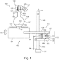
- Fig. 1 schematically illustrates a fluid analysis system 150 having a device 100 for preparing a distillation measurement of a liquid according to an embodiment of the present invention.
- the fluid analysis system 150 includes a device 100 for preparation a distillation measurement of a liquid according to an embodiment of the present invention.
- the device 100 comprises a heater 101, for example an electric heater with heating coils, to which a perforated plate 103 selected from a group of standardized perforated plates can be placed, in particular on an upper side of the heater 101.
- the heater 101 is for heating the liquid contained in the Perforated plate 103 placed on container 105 for performing a standardized test for determining evaporation properties of the liquid.
- the liquid 107 to be examined is located in the container 105, which in the illustrated embodiment is designed as a glass round-bottomed flask.
- the device 100 further comprises an electrical traversing system 110, which is designed to move the heater 101 (in particular together with the perforated plate 103) vertically upward along a vertical direction 111 and to interrupt another method of the heating system, if a pressing force F on the heater 101 placed perforated plate 103 against the container 105 reaches a threshold.
- an electrical traversing system 110 which is designed to move the heater 101 (in particular together with the perforated plate 103) vertically upward along a vertical direction 111 and to interrupt another method of the heating system, if a pressing force F on the heater 101 placed perforated plate 103 against the container 105 reaches a threshold.
- the container 105 is closed at its upper end by a device 120 for closing the container, which in Fig. 1 only schematically illustrated.
- the device 120 seals the container 105, in particular an upper opening of the container vapor-tight and also allows a temperature measurement by means of at least one temperature sensor 121, which is provided at the end of a rod 123.
- the rod is completely guided by a closure part 125 of the device 120, wherein the closure part 125 with an outer surface on a inner surface of an opening wall 127 of the container 105 is tightly.
- the device 120 further comprises a support member 129 which projects laterally downwardly inclined and is connected to a counterpart 131 of an auxiliary device shown broken away, in particular a form-fitting manner is connected to support the device 120 for closing the container together with the container 105.
- the movement system 110 comprises a carrier system 133, of which the heater 101 is mounted.
- the device 100 is designed to monitor and / or determine a variable indicative of a length and / or position z along a travel path w of the carrier system 133.
- the device 100 is further configured to move the carrier system 133 from an initial position za to an end position ze of the carrier system, in which the pressing force F reaches the threshold value.
- Fig. 1 the state is illustrated in which the carrier system is in the final position ze, at which the pressing force F reaches the threshold.
- the circular edge 135 of the perforated plate 103 exerts the pressing force F on a circular contact surface on the outer surface 137 of the container 105.
- the associated size indicative of the position along the travel has a first value, e.g. w1
- the size indicative of the position along the travel w associated with the end position ze has a second value, e.g. w2.
- the device 100 is further configured to calculate the difference of the first value w1 and the second value w2 as the difference value w2-w1 indicative of the travel distance covered thereby.
- the difference value may e.g. equal to the number of steps of a stepping motor traveled by a stepping motor between the home position za and the end position ze. Based on the difference value, e.g. the type and / or the size of the perforated plate can be determined.
- the support system 133 includes a support member 139 from which the heater 101 is carried.
- the support element can eg as a table and / or as a Arm and / or be formed as a rod on which the heater 101 is suitably supported or placed.
- the carrier system 133 further comprises a traversing element 141, which is for driving in engagement with a spindle 153, which is arranged along a rail 143. Further, the traversing element is guided by the vertically oriented rail 111 143 along which the travel path w runs.
- the carrier system 133 further comprises a force measuring device 145, via which the carrier element 139 is coupled to the displacement element 141.
- the traversing element may e.g. be designed as a Verfahrarm or as a driving table. Only the traversing element 141 is standing, e.g. via a toothed rail, with the arranged in or at the vertical rail 143 spindle engaged, but not the support member 139. The support member 139 and thus the heater 101 is only secondarily by means of the force measuring device 145 during movement of the traversing element 141 indirectly or secondarily proceed.
- the force measuring device 145 has a spring 147, one end of which is attached to the displacement element 141 and the other end to the support element 139. Furthermore, the force measuring device 145 comprises a light barrier 149, which is coupled to a stepping motor 151, which drives the spindle 153. An interruption element 155 of the light barrier 149 interrupts a light beam 157, which is emitted by a light source 159, so as not to be detected by a detector 161, if the spring 147 is compressed to the extent that the threshold value of the pressing force F is reached.
- Fig. 1 illustrates this condition by placing the interruption element 155 between the light source 159 and the detector 161, whereupon the motor 151 is driven to stop further movement.
- the counterpart 131 of the support member 129 of the device 120 for closing the container 105 may be attached to the rail 143 or may be attached to another auxiliary device.
- an attachment or fixed mechanical connection between the counterpart 131 and the rail 143 is advantageous, in order to bring the container into a defined predetermined position relative to the electrical movement system 110.
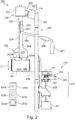
- Fig. 2 schematically illustrates a fluid analysis system 250 according to an embodiment of the present invention which includes a device 200 for preparing a distillation measurement of a fluid.
- the fluid analysis system 250 which is in Fig. 2 is similar to the fluid analysis system 150 which is illustrated in FIG Fig. 1 is illustrated.
- the liquid analysis system 250 is configured as an automatic distillation unit for determining vaporization characteristics of the liquid residing in the container 205 according to at least one standardized test.
- the liquid analysis system 250 comprises the container 205 with an opening at an upper end and in particular with a leading to a capacitor 269 branch 263.
- the liquid to be examined 207 is included.
- the liquid analysis system 250 comprises a device 220 for closing the container 205.
- This device 220 comprises at least one temperature measuring system, in particular for measuring a vapor temperature of the liquid within the container 205 in an interior 264.
- the temperature measuring system comprises a rod 223 with a temperature sensor 221 a lower end, so that it is disposed within the container in the inner space 264, and in particular in the vertical height is set or adjustable so that it is approximately on the Height of the branch 263 is located, which leads to the capacitor 269, which is only schematically illustrated.
- the condensate generated in the condenser 269 is collected in a collecting cylinder 271, whereby the collecting volume is measured.
- the device 220 further includes a closure member 225 for closing the container, the closure member 225 having an unillustrated through-opening through which a portion of the rod 223 is routed such that the temperature sensor 221 is disposed within the container, particularly near the branch 263.
- the device 220 also comprises a support part 229 projecting above the closure part 225 transversely to the longitudinal direction of the bar 223, which can be pushed into one another with a counterpart 231.
- the counterpart 231 is fixedly connected to the rail 243, along which the travel path w runs, along which the heater 201 is movable together with the perforated plate 203.
- the liquid analysis system 250 thus also includes the apparatus 200 for preparing a distillation measurement of the liquid and in particular a plurality of standardized perforated plates, which can be placed on the heater.
- the apparatus 200 for preparing a distillation measurement of the liquid and in particular a plurality of standardized perforated plates, which can be placed on the heater.
- perforated plate 203a placed on the heater 201 further perforated plates 203b, c and d are illustrated which have central openings or holes of different sizes.
- a positioning system 210 For moving (moving) the heater with the perforated plate, a positioning system 210 is provided.
- the positioning system 210 comprises an electric stepping motor 251, which moves a traversing element 241 which is connected to a supporting element 239 via a spring 247.
- the spring together with a light barrier 249, is part of a force measuring device 245 which has a similar function as with reference to FIG Fig. 1 is explained.
- a not illustrated rack transforms a rotational movement of a spindle, which is driven by the stepping motor 251, in a straight-line movement along the travel path w.
- an automated method wherein the user selects the orifice plate as usual, such as one of the orifice plates 203a, 203b, 203c, 203d incorporated in FIG Fig. 2 are illustrated.
- the selected perforated plate is placed on the heater 201 and an automatic startup is started.
- the heater together with the selected perforated plate for example 203a, is fully automatically pushed or moved up by a lift (or traversing system 210) to the piston or, in general, the container 205.
- a spring 247 is, as soon as the perforated plate is applied to the piston, compressed.
- a threshold value of the spring force F is reached or exceeded (which is determined indirectly via a travel measurement with a light barrier 249), the movement of the lift or of the positioning system is stopped. Damage to the piston is thereby avoided.
- the traverse path ie, the steps of the stepping motor, eg, made so far
- the traverse path is calculated back to the diameter of the hole within the selected orifice plate 203a and it is recognized whether the correct orifice plate has been selected to perform a previously specified standardized test.
- Embodiments of a fluid analysis system may be configured to perform standardized tests according to ASTM D86, ASTM D850, D1078 or ISO 1078 standards.
- ASTM D86, ASTM D850, D1078 or ISO 1078 standards prescribe four perforated plates with four different inner diameters of the openings.
- the heater is brought together with the perforated plate from below to the piston.
- the perforated plate must close tightly with the piston. This is ensured by gently pressing the heater against the piston.
- the temperature of the steam is determined in embodiments of the present invention by means of a Pt100 temperature sensor (eg, the sensor 221 which is used in FIG Fig. 2 illustrated).
- the temperature sensor 221 is guided via a rod 223 through the closure part 225.
- the device 220 for closing the container next to the temperature sensor 221 comprises a further temperature sensor 222, which measures the temperature at a bottom of the container, the further temperature sensor 222 transmits via a further rod 224 measurement signals in an interior 226 within the device 220, in which, for example, an electronic circuit is included to process the measurement signals, and also the measurement signals of the (first) temperature sensor 221 before and in particular to perform a calibration, and in particular can also convert to digital signals.
- a dry point can be determined, ie a point when the last remainder of the liquid within the container has evaporated, since in this case the temperature at the bottom of the container rises sharply.
- Embodiments of the present invention further make it possible to avoid operator error and in particular to check before starting a distillation measurement according to a standardized test, whether always the respective standard and compatible with the selected test hole plate was used.
- the user can select one of the four perforated plates prescribed by the standard in an automated unit depending on the liquid sample or distillation program and also select the associated piston or container and start a measurement.
- a lift then leads the perforated plate from below to the piston and presses it with a defined force on the piston to seal the gap exactly.
- the container 105 and the perforated plate 103 lying on the heater 101 are pressed against each other.
- the lift (or the support element 139) is moved by a stepper motor 151 which moves the receptacle of the heater 101 along the guide rail 143 via a spindle drive 153.
- a spindle drive 153 There are limit switches at the two end points, so that the travel path of the lift is clearly defined.
- the force is measured by means of a spring 147 and a light barrier 149 with switching plate 155.
- the lifting of the lift at a certain force via the upsetting of a spring with a defined spring constant.
- piston perforated plate traverse 125 ml 50 28 mm 125 ml 38 25 mm 125 ml 32 23 mm 125 ml 25 20 mm 200 ml 50 38 mm 200 ml 38 35 mm 200 ml 32 33 mm 200 ml 25 30 mm
- a tolerance or accuracy of +/- 1 mm applies.
- the user can check whether he has selected the standard perforated plate and the right piston. If the user has selected the wrong orifice plate or the wrong piston, a warning may appear on a display or an audible signal may sound. Optionally, the user may be prompted to swap the orifice plate or piston, or it is prohibited to start a distillation measurement unless the correct components have been used.
Landscapes
- Chemical & Material Sciences (AREA)
- Health & Medical Sciences (AREA)
- Chemical Kinetics & Catalysis (AREA)
- Biochemistry (AREA)
- General Physics & Mathematics (AREA)
- Physics & Mathematics (AREA)
- Life Sciences & Earth Sciences (AREA)
- Analytical Chemistry (AREA)
- Pathology (AREA)
- General Health & Medical Sciences (AREA)
- Immunology (AREA)
- Clinical Laboratory Science (AREA)
- Dispersion Chemistry (AREA)
- Toxicology (AREA)
- Investigating Or Analyzing Materials Using Thermal Means (AREA)
- Sampling And Sample Adjustment (AREA)
- Vaporization, Distillation, Condensation, Sublimation, And Cold Traps (AREA)
- Devices For Use In Laboratory Experiments (AREA)
Applications Claiming Priority (1)
| Application Number | Priority Date | Filing Date | Title |
|---|---|---|---|
| DE102018111816.3A DE102018111816B4 (de) | 2018-05-16 | 2018-05-16 | Vorbereitung einer Destillationsmessung |
Publications (3)
| Publication Number | Publication Date |
|---|---|
| EP3570017A2 true EP3570017A2 (fr) | 2019-11-20 |
| EP3570017A3 EP3570017A3 (fr) | 2019-12-18 |
| EP3570017B1 EP3570017B1 (fr) | 2022-12-21 |
Family
ID=66554238
Family Applications (1)
| Application Number | Title | Priority Date | Filing Date |
|---|---|---|---|
| EP19174595.9A Active EP3570017B1 (fr) | 2018-05-16 | 2019-05-15 | Préparation d'une mesure de distillation |
Country Status (5)
| Country | Link |
|---|---|
| US (1) | US10837929B2 (fr) |
| EP (1) | EP3570017B1 (fr) |
| JP (1) | JP7334885B2 (fr) |
| CN (1) | CN110501372A (fr) |
| DE (1) | DE102018111816B4 (fr) |
Families Citing this family (4)
| Publication number | Priority date | Publication date | Assignee | Title |
|---|---|---|---|---|
| WO2019144730A1 (fr) | 2018-01-23 | 2019-08-01 | 北京师范大学 | Évaporateur rotatif capable de quantifier avec précision un liquide concentré et/ou un distillat |
| WO2023288224A1 (fr) * | 2021-07-13 | 2023-01-19 | Petroleum Analyzer Company L.P. | Systèmes et procédés servant à déterminer les caractéristiques de distillation d'échantillons de pétrole par distillation partielle |
| CN114345434A (zh) * | 2022-01-12 | 2022-04-15 | 泉州市全通光电科技有限公司 | 一种仪器烧瓶自动夹持加热定位装置及作业方法 |
| DE102024107859A1 (de) * | 2024-03-19 | 2025-09-25 | Hans Heidolph GmbH | Rührsystem |
Citations (2)
| Publication number | Priority date | Publication date | Assignee | Title |
|---|---|---|---|---|
| EP1967848A1 (fr) | 2007-02-13 | 2008-09-10 | Instrumentation Scientifique de Laboratoire ISL | Dispositif de décodage de plaques isolantes pour un appareil de distillation normalisé |
| EP1967269A1 (fr) | 2007-02-13 | 2008-09-10 | Instrumentation Scientifique de Laboratoire ISL | Dispositif de positionnement automatique assisté d'une enceinte de chauffage contre un ballon de distillation |
Family Cites Families (21)
| Publication number | Priority date | Publication date | Assignee | Title |
|---|---|---|---|---|
| JPS5225116B2 (fr) * | 1972-07-13 | 1977-07-05 | ||
| DE2419156C3 (de) * | 1974-04-20 | 1978-08-03 | W.C. Heraeus Gmbh, 6450 Hanau | Destillationsautomat mit Fraktionssammler |
| US4528635A (en) * | 1982-06-07 | 1985-07-09 | Gca Corporation | Automatic distillation apparatus |
| JPS64963Y2 (fr) * | 1984-10-12 | 1989-01-11 | ||
| RU2153664C1 (ru) * | 1999-03-04 | 2000-07-27 | Попов Юрий Анатольевич | Способ экспрессного определения теплопроводности твердых материалов и устройство для его осуществления |
| AT412025B (de) * | 2002-04-24 | 2004-08-26 | Grabner Instr Messtechnik Ges | Verfahren zur aufnahme der siedekurve von flüssigkeiten sowie vorrichtung zur durchführung dieses verfahrens |
| CA2524689C (fr) * | 2003-04-24 | 2012-05-22 | Shell Canada Limited | Procedes thermiques pour formations souterraines |
| KR20060072907A (ko) * | 2004-12-24 | 2006-06-28 | 한국항공우주연구원 | 히터를 이용한 수직형 가열 시험장치 |
| FR2912319B1 (fr) * | 2007-02-13 | 2009-04-24 | Instrumentation Scient De Labo | Procede de distillation automatique d'echantillons liquides sous pression atmospherique dans un appareil de distillation normalise. |
| CA3090851C (fr) * | 2010-03-15 | 2023-03-07 | The Board Of Trustees Of The Leland Stanford Junior University | Capteur acoustique compatible avec une fibre optique |
| US8367022B2 (en) | 2010-05-03 | 2013-02-05 | Integra Biosciences Corp. | Unintended motion control for manually directed multi-channel electronic pipettor |
| DE202011106534U1 (de) | 2011-10-08 | 2013-01-09 | Knf Neuberger Gmbh | Rotationsverdampfer |
| CN103196939B (zh) * | 2013-04-01 | 2015-06-10 | 北京航空航天大学 | 一种测量材料高温蠕变裂纹扩展临界温度的方法 |
| CN104959176B (zh) * | 2015-05-29 | 2017-07-04 | 武汉理工大学 | 一种圆底烧瓶的测温装置 |
| RU2610550C1 (ru) * | 2015-09-14 | 2017-02-13 | Шлюмберже Текнолоджи Б.В. | Способ определения температурного коэффициента линейного расширения материала и устройство для его осуществления |
| US9714149B2 (en) | 2015-10-30 | 2017-07-25 | Ncr Corporation | Media deskew |
| EP3196648B1 (fr) * | 2016-01-22 | 2021-03-31 | Roche Diagniostics GmbH | Dispositif de levage d'un tube d'échantillon |
| DE102016211413A1 (de) * | 2016-06-24 | 2017-12-28 | Brose Fahrzeugteile Gmbh & Co. Kommanditgesellschaft, Bamberg | Verfahren zum Betrieb einer elektromotorischen Verstelleinrichtung |
| US10363495B2 (en) * | 2016-08-03 | 2019-07-30 | Instrumentation Scientifique de Laboratoire—I.S.L. | System and method for auto distilling liquids at strictly defined conditions regardless of composition |
| DE102016117521A1 (de) * | 2016-09-16 | 2018-03-22 | PILODIST GmbH | Vorrichtung zum Ermitteln der Siedetemperatur einer Flüssigkeit |
| KR101791624B1 (ko) * | 2017-05-11 | 2017-10-30 | 동문이엔티(주) | 자동 증류 장치 |
-
2018
- 2018-05-16 DE DE102018111816.3A patent/DE102018111816B4/de active Active
-
2019
- 2019-05-15 CN CN201910401452.3A patent/CN110501372A/zh active Pending
- 2019-05-15 EP EP19174595.9A patent/EP3570017B1/fr active Active
- 2019-05-15 US US16/413,532 patent/US10837929B2/en active Active
- 2019-05-16 JP JP2019092762A patent/JP7334885B2/ja active Active
Patent Citations (2)
| Publication number | Priority date | Publication date | Assignee | Title |
|---|---|---|---|---|
| EP1967848A1 (fr) | 2007-02-13 | 2008-09-10 | Instrumentation Scientifique de Laboratoire ISL | Dispositif de décodage de plaques isolantes pour un appareil de distillation normalisé |
| EP1967269A1 (fr) | 2007-02-13 | 2008-09-10 | Instrumentation Scientifique de Laboratoire ISL | Dispositif de positionnement automatique assisté d'une enceinte de chauffage contre un ballon de distillation |
Also Published As
| Publication number | Publication date |
|---|---|
| DE102018111816B4 (de) | 2021-01-21 |
| DE102018111816A1 (de) | 2019-11-21 |
| EP3570017B1 (fr) | 2022-12-21 |
| US20190353604A1 (en) | 2019-11-21 |
| CN110501372A (zh) | 2019-11-26 |
| EP3570017A3 (fr) | 2019-12-18 |
| US10837929B2 (en) | 2020-11-17 |
| JP7334885B2 (ja) | 2023-08-29 |
| JP2019200207A (ja) | 2019-11-21 |
Similar Documents
| Publication | Publication Date | Title |
|---|---|---|
| EP3570017B1 (fr) | Préparation d'une mesure de distillation | |
| EP3452833B1 (fr) | Procédé pour déterminer la position d'un bras robotisé dans un système de manipulation de liquide et système de manipulation de liquide correspondant | |
| EP2519808B1 (fr) | Procédé et dispositif de détection de limites de phase et appareil de laboratoire équipé en conséquence | |
| EP2350675B1 (fr) | Dispositif d'analyse automatisé comportant un dispositif automatique de prélèvement par pipette et un dispositif de mesure pour déterminer la position de la pointe de l'aiguille de prélèvement par pipette | |
| EP0793093A1 (fr) | Méthode et appareil pour l'analyse automatique du point d'inflammation | |
| DE102008043412A1 (de) | Vorrichtung zur Bestimmung und/oder Überwachung einer Prozessgröße eines Mediums | |
| EP2533035A1 (fr) | Dispositif et procédé de détection des caractéristiques de matériaux | |
| DE1176573B (de) | Vorrichtung zur Bestimmung der Lage der Grenzflaeche zwischen zwei getrennten Komponenten in einer Zentrifuge | |
| EP3569297A1 (fr) | Bouchon pour mesures de distillation automatique | |
| EP2343518A1 (fr) | Sonde de mesure pour la détermination d'un niveau de remplissage d'un liquide | |
| EP2489996A1 (fr) | Appareil ménager avec capteur de niveau d'eau | |
| EP1899689B1 (fr) | Dispositif pour determiner la quantite et/ou surveiller le niveau d'une substance | |
| DE2658215A1 (de) | Vorrichtung zur messung der eigenschaft bzw. qualitaet einer fluessigkeit | |
| EP2530440B1 (fr) | Procédé, dispositif et appareil de laboratoire pour vérifier le fonctionnement d'un dispositif de détection de limites de phases de manière capacitive | |
| EP0289499B1 (fr) | Procede et dispositif de mesure de la temperature d'ebullition | |
| EP2481481B1 (fr) | Procédé de réglage pour appareils de lavage dotés de microplaquettes | |
| WO2017125214A1 (fr) | Dispositif et procédé de préparation d'une analyse d'un gaz dissous dans un fluide et système d'analyse pour l'analyse d'un gaz dissous dans un fluide | |
| EP2503425B1 (fr) | Dispositif et procédé de commande/réglage d'un niveau de remplissage | |
| DE4308996C2 (de) | Meßgerät für eine Fett- oder Ölschicht | |
| DE102015108092A1 (de) | Pipettiervorrichtung | |
| WO2014019665A1 (fr) | Procédé pour quantifier la stabilité à l'oxydation d'un carburant | |
| DE1034885B (de) | Verfahren zum Messen von AEnderungen des Grades der Ungesaettigtheit von tierischen oder pflanzlichen OElen bzw. daraus stammenden Fettsaeuren | |
| DE102024200905A1 (de) | Rheometer und Verfahren zur Bestimmung rheologischer Eigenschaften eines viskoelastischen Materials | |
| EP0585910A2 (fr) | Capteur d'inclinaison | |
| DE1791035C (de) | Anordnung zur elektrischen Hochspannungsprüfung scheibenförmiger Isolierstoffproben |
Legal Events
| Date | Code | Title | Description |
|---|---|---|---|
| PUAI | Public reference made under article 153(3) epc to a published international application that has entered the european phase |
Free format text: ORIGINAL CODE: 0009012 |
|
| STAA | Information on the status of an ep patent application or granted ep patent |
Free format text: STATUS: THE APPLICATION HAS BEEN PUBLISHED |
|
| PUAL | Search report despatched |
Free format text: ORIGINAL CODE: 0009013 |
|
| AK | Designated contracting states |
Kind code of ref document: A2 Designated state(s): AL AT BE BG CH CY CZ DE DK EE ES FI FR GB GR HR HU IE IS IT LI LT LU LV MC MK MT NL NO PL PT RO RS SE SI SK SM TR |
|
| AX | Request for extension of the european patent |
Extension state: BA ME |
|
| AK | Designated contracting states |
Kind code of ref document: A3 Designated state(s): AL AT BE BG CH CY CZ DE DK EE ES FI FR GB GR HR HU IE IS IT LI LT LU LV MC MK MT NL NO PL PT RO RS SE SI SK SM TR |
|
| AX | Request for extension of the european patent |
Extension state: BA ME |
|
| RIC1 | Information provided on ipc code assigned before grant |
Ipc: B01D 3/00 20060101ALI20191111BHEP Ipc: G01N 25/10 20060101AFI20191111BHEP |
|
| STAA | Information on the status of an ep patent application or granted ep patent |
Free format text: STATUS: REQUEST FOR EXAMINATION WAS MADE |
|
| 17P | Request for examination filed |
Effective date: 20200324 |
|
| RBV | Designated contracting states (corrected) |
Designated state(s): AL AT BE BG CH CY CZ DE DK EE ES FI FR GB GR HR HU IE IS IT LI LT LU LV MC MK MT NL NO PL PT RO RS SE SI SK SM TR |
|
| STAA | Information on the status of an ep patent application or granted ep patent |
Free format text: STATUS: EXAMINATION IS IN PROGRESS |
|
| 17Q | First examination report despatched |
Effective date: 20210707 |
|
| GRAP | Despatch of communication of intention to grant a patent |
Free format text: ORIGINAL CODE: EPIDOSNIGR1 |
|
| STAA | Information on the status of an ep patent application or granted ep patent |
Free format text: STATUS: GRANT OF PATENT IS INTENDED |
|
| INTG | Intention to grant announced |
Effective date: 20220915 |
|
| GRAS | Grant fee paid |
Free format text: ORIGINAL CODE: EPIDOSNIGR3 |
|
| GRAA | (expected) grant |
Free format text: ORIGINAL CODE: 0009210 |
|
| STAA | Information on the status of an ep patent application or granted ep patent |
Free format text: STATUS: THE PATENT HAS BEEN GRANTED |
|
| REG | Reference to a national code |
Ref country code: DE Ref legal event code: R108 Ref document number: 502019006565 Country of ref document: DE |
|
| AK | Designated contracting states |
Kind code of ref document: B1 Designated state(s): AL AT BE BG CH CY CZ DE DK EE ES FI FR GB GR HR HU IE IS IT LI LT LU LV MC MK MT NL NO PL PT RO RS SE SI SK SM TR |
|
| REG | Reference to a national code |
Ref country code: GB Ref legal event code: FG4D Free format text: NOT ENGLISH |
|
| REG | Reference to a national code |
Ref country code: DE Ref legal event code: R096 Ref document number: 502019006565 Country of ref document: DE |
|
| REG | Reference to a national code |
Ref country code: CH Ref legal event code: EP |
|
| REG | Reference to a national code |
Ref country code: AT Ref legal event code: REF Ref document number: 1539345 Country of ref document: AT Kind code of ref document: T Effective date: 20230115 |
|
| REG | Reference to a national code |
Ref country code: IE Ref legal event code: FG4D Free format text: LANGUAGE OF EP DOCUMENT: GERMAN |
|
| RBV | Designated contracting states (corrected) |
Designated state(s): AL AT BE BG CH CY CZ DK EE ES FI FR GB GR HR HU IE IS IT LI LT LU LV MC MK MT NL NO PL PT RO RS SE SI SK SM TR |
|
| REG | Reference to a national code |
Ref country code: DE Ref legal event code: R107 Ref document number: 502019006565 Country of ref document: DE |
|
| REG | Reference to a national code |
Ref country code: NL Ref legal event code: FP |
|
| REG | Reference to a national code |
Ref country code: LT Ref legal event code: MG9D |
|
| PG25 | Lapsed in a contracting state [announced via postgrant information from national office to epo] |
Ref country code: SE Free format text: LAPSE BECAUSE OF FAILURE TO SUBMIT A TRANSLATION OF THE DESCRIPTION OR TO PAY THE FEE WITHIN THE PRESCRIBED TIME-LIMIT Effective date: 20221221 Ref country code: NO Free format text: LAPSE BECAUSE OF FAILURE TO SUBMIT A TRANSLATION OF THE DESCRIPTION OR TO PAY THE FEE WITHIN THE PRESCRIBED TIME-LIMIT Effective date: 20230321 Ref country code: LT Free format text: LAPSE BECAUSE OF FAILURE TO SUBMIT A TRANSLATION OF THE DESCRIPTION OR TO PAY THE FEE WITHIN THE PRESCRIBED TIME-LIMIT Effective date: 20221221 Ref country code: FI Free format text: LAPSE BECAUSE OF FAILURE TO SUBMIT A TRANSLATION OF THE DESCRIPTION OR TO PAY THE FEE WITHIN THE PRESCRIBED TIME-LIMIT Effective date: 20221221 |
|
| PG25 | Lapsed in a contracting state [announced via postgrant information from national office to epo] |
Ref country code: RS Free format text: LAPSE BECAUSE OF FAILURE TO SUBMIT A TRANSLATION OF THE DESCRIPTION OR TO PAY THE FEE WITHIN THE PRESCRIBED TIME-LIMIT Effective date: 20221221 Ref country code: LV Free format text: LAPSE BECAUSE OF FAILURE TO SUBMIT A TRANSLATION OF THE DESCRIPTION OR TO PAY THE FEE WITHIN THE PRESCRIBED TIME-LIMIT Effective date: 20221221 Ref country code: HR Free format text: LAPSE BECAUSE OF FAILURE TO SUBMIT A TRANSLATION OF THE DESCRIPTION OR TO PAY THE FEE WITHIN THE PRESCRIBED TIME-LIMIT Effective date: 20221221 Ref country code: GR Free format text: LAPSE BECAUSE OF FAILURE TO SUBMIT A TRANSLATION OF THE DESCRIPTION OR TO PAY THE FEE WITHIN THE PRESCRIBED TIME-LIMIT Effective date: 20230322 |
|
| PG25 | Lapsed in a contracting state [announced via postgrant information from national office to epo] |
Ref country code: SM Free format text: LAPSE BECAUSE OF FAILURE TO SUBMIT A TRANSLATION OF THE DESCRIPTION OR TO PAY THE FEE WITHIN THE PRESCRIBED TIME-LIMIT Effective date: 20221221 Ref country code: RO Free format text: LAPSE BECAUSE OF FAILURE TO SUBMIT A TRANSLATION OF THE DESCRIPTION OR TO PAY THE FEE WITHIN THE PRESCRIBED TIME-LIMIT Effective date: 20221221 Ref country code: PT Free format text: LAPSE BECAUSE OF FAILURE TO SUBMIT A TRANSLATION OF THE DESCRIPTION OR TO PAY THE FEE WITHIN THE PRESCRIBED TIME-LIMIT Effective date: 20230421 Ref country code: ES Free format text: LAPSE BECAUSE OF FAILURE TO SUBMIT A TRANSLATION OF THE DESCRIPTION OR TO PAY THE FEE WITHIN THE PRESCRIBED TIME-LIMIT Effective date: 20221221 Ref country code: EE Free format text: LAPSE BECAUSE OF FAILURE TO SUBMIT A TRANSLATION OF THE DESCRIPTION OR TO PAY THE FEE WITHIN THE PRESCRIBED TIME-LIMIT Effective date: 20221221 Ref country code: CZ Free format text: LAPSE BECAUSE OF FAILURE TO SUBMIT A TRANSLATION OF THE DESCRIPTION OR TO PAY THE FEE WITHIN THE PRESCRIBED TIME-LIMIT Effective date: 20221221 |
|
| PG25 | Lapsed in a contracting state [announced via postgrant information from national office to epo] |
Ref country code: SK Free format text: LAPSE BECAUSE OF FAILURE TO SUBMIT A TRANSLATION OF THE DESCRIPTION OR TO PAY THE FEE WITHIN THE PRESCRIBED TIME-LIMIT Effective date: 20221221 Ref country code: PL Free format text: LAPSE BECAUSE OF FAILURE TO SUBMIT A TRANSLATION OF THE DESCRIPTION OR TO PAY THE FEE WITHIN THE PRESCRIBED TIME-LIMIT Effective date: 20221221 Ref country code: IS Free format text: LAPSE BECAUSE OF FAILURE TO SUBMIT A TRANSLATION OF THE DESCRIPTION OR TO PAY THE FEE WITHIN THE PRESCRIBED TIME-LIMIT Effective date: 20230421 Ref country code: AL Free format text: LAPSE BECAUSE OF FAILURE TO SUBMIT A TRANSLATION OF THE DESCRIPTION OR TO PAY THE FEE WITHIN THE PRESCRIBED TIME-LIMIT Effective date: 20221221 |
|
| PLBE | No opposition filed within time limit |
Free format text: ORIGINAL CODE: 0009261 |
|
| STAA | Information on the status of an ep patent application or granted ep patent |
Free format text: STATUS: NO OPPOSITION FILED WITHIN TIME LIMIT |
|
| PG25 | Lapsed in a contracting state [announced via postgrant information from national office to epo] |
Ref country code: DK Free format text: LAPSE BECAUSE OF FAILURE TO SUBMIT A TRANSLATION OF THE DESCRIPTION OR TO PAY THE FEE WITHIN THE PRESCRIBED TIME-LIMIT Effective date: 20221221 |
|
| 26N | No opposition filed |
Effective date: 20230922 |
|
| REG | Reference to a national code |
Ref country code: CH Ref legal event code: PL |
|
| PG25 | Lapsed in a contracting state [announced via postgrant information from national office to epo] |
Ref country code: MC Free format text: LAPSE BECAUSE OF FAILURE TO SUBMIT A TRANSLATION OF THE DESCRIPTION OR TO PAY THE FEE WITHIN THE PRESCRIBED TIME-LIMIT Effective date: 20221221 |
|
| GBPC | Gb: european patent ceased through non-payment of renewal fee |
Effective date: 20230515 |
|
| REG | Reference to a national code |
Ref country code: BE Ref legal event code: MM Effective date: 20230531 |
|
| PG25 | Lapsed in a contracting state [announced via postgrant information from national office to epo] |
Ref country code: SI Free format text: LAPSE BECAUSE OF FAILURE TO SUBMIT A TRANSLATION OF THE DESCRIPTION OR TO PAY THE FEE WITHIN THE PRESCRIBED TIME-LIMIT Effective date: 20221221 Ref country code: MC Free format text: LAPSE BECAUSE OF FAILURE TO SUBMIT A TRANSLATION OF THE DESCRIPTION OR TO PAY THE FEE WITHIN THE PRESCRIBED TIME-LIMIT Effective date: 20221221 Ref country code: LU Free format text: LAPSE BECAUSE OF NON-PAYMENT OF DUE FEES Effective date: 20230515 Ref country code: LI Free format text: LAPSE BECAUSE OF NON-PAYMENT OF DUE FEES Effective date: 20230531 Ref country code: CH Free format text: LAPSE BECAUSE OF NON-PAYMENT OF DUE FEES Effective date: 20230531 |
|
| REG | Reference to a national code |
Ref country code: IE Ref legal event code: MM4A |
|
| PG25 | Lapsed in a contracting state [announced via postgrant information from national office to epo] |
Ref country code: IE Free format text: LAPSE BECAUSE OF NON-PAYMENT OF DUE FEES Effective date: 20230515 |
|
| PG25 | Lapsed in a contracting state [announced via postgrant information from national office to epo] |
Ref country code: IE Free format text: LAPSE BECAUSE OF NON-PAYMENT OF DUE FEES Effective date: 20230515 Ref country code: GB Free format text: LAPSE BECAUSE OF NON-PAYMENT OF DUE FEES Effective date: 20230515 |
|
| PG25 | Lapsed in a contracting state [announced via postgrant information from national office to epo] |
Ref country code: IT Free format text: LAPSE BECAUSE OF FAILURE TO SUBMIT A TRANSLATION OF THE DESCRIPTION OR TO PAY THE FEE WITHIN THE PRESCRIBED TIME-LIMIT Effective date: 20221221 Ref country code: BE Free format text: LAPSE BECAUSE OF NON-PAYMENT OF DUE FEES Effective date: 20230531 |
|
| PG25 | Lapsed in a contracting state [announced via postgrant information from national office to epo] |
Ref country code: BG Free format text: LAPSE BECAUSE OF FAILURE TO SUBMIT A TRANSLATION OF THE DESCRIPTION OR TO PAY THE FEE WITHIN THE PRESCRIBED TIME-LIMIT Effective date: 20221221 |
|
| PG25 | Lapsed in a contracting state [announced via postgrant information from national office to epo] |
Ref country code: BG Free format text: LAPSE BECAUSE OF FAILURE TO SUBMIT A TRANSLATION OF THE DESCRIPTION OR TO PAY THE FEE WITHIN THE PRESCRIBED TIME-LIMIT Effective date: 20221221 |
|
| PGFP | Annual fee paid to national office [announced via postgrant information from national office to epo] |
Ref country code: NL Payment date: 20250515 Year of fee payment: 7 |
|
| REG | Reference to a national code |
Ref country code: AT Ref legal event code: MM01 Ref document number: 1539345 Country of ref document: AT Kind code of ref document: T Effective date: 20240515 |
|
| PGFP | Annual fee paid to national office [announced via postgrant information from national office to epo] |
Ref country code: FR Payment date: 20250528 Year of fee payment: 7 |
|
| PG25 | Lapsed in a contracting state [announced via postgrant information from national office to epo] |
Ref country code: AT Free format text: LAPSE BECAUSE OF NON-PAYMENT OF DUE FEES Effective date: 20240515 |
|
| PG25 | Lapsed in a contracting state [announced via postgrant information from national office to epo] |
Ref country code: CY Free format text: LAPSE BECAUSE OF FAILURE TO SUBMIT A TRANSLATION OF THE DESCRIPTION OR TO PAY THE FEE WITHIN THE PRESCRIBED TIME-LIMIT; INVALID AB INITIO Effective date: 20190515 |
|
| PG25 | Lapsed in a contracting state [announced via postgrant information from national office to epo] |
Ref country code: HU Free format text: LAPSE BECAUSE OF FAILURE TO SUBMIT A TRANSLATION OF THE DESCRIPTION OR TO PAY THE FEE WITHIN THE PRESCRIBED TIME-LIMIT; INVALID AB INITIO Effective date: 20190515 |
|
| PG25 | Lapsed in a contracting state [announced via postgrant information from national office to epo] |
Ref country code: TR Free format text: LAPSE BECAUSE OF FAILURE TO SUBMIT A TRANSLATION OF THE DESCRIPTION OR TO PAY THE FEE WITHIN THE PRESCRIBED TIME-LIMIT Effective date: 20221221 |
|
| PGFP | Annual fee paid to national office [announced via postgrant information from national office to epo] |
Ref country code: AT Payment date: 20260410 Year of fee payment: 5 |