EP3570084A1 - Dispositif de transmission de signaux optiques entre deux unités structurales rotatives - Google Patents
Dispositif de transmission de signaux optiques entre deux unités structurales rotatives Download PDFInfo
- Publication number
- EP3570084A1 EP3570084A1 EP18172688.6A EP18172688A EP3570084A1 EP 3570084 A1 EP3570084 A1 EP 3570084A1 EP 18172688 A EP18172688 A EP 18172688A EP 3570084 A1 EP3570084 A1 EP 3570084A1
- Authority
- EP
- European Patent Office
- Prior art keywords
- conical
- conical surface
- clamping sleeve
- thread
- clamping
- Prior art date
- Legal status (The legal status is an assumption and is not a legal conclusion. Google has not performed a legal analysis and makes no representation as to the accuracy of the status listed.)
- Granted
Links
Images


Classifications
-
- F—MECHANICAL ENGINEERING; LIGHTING; HEATING; WEAPONS; BLASTING
- F16—ENGINEERING ELEMENTS AND UNITS; GENERAL MEASURES FOR PRODUCING AND MAINTAINING EFFECTIVE FUNCTIONING OF MACHINES OR INSTALLATIONS; THERMAL INSULATION IN GENERAL
- F16C—SHAFTS; FLEXIBLE SHAFTS; ELEMENTS OR CRANKSHAFT MECHANISMS; ROTARY BODIES OTHER THAN GEARING ELEMENTS; BEARINGS
- F16C19/00—Bearings with rolling contact, for exclusively rotary movement
- F16C19/02—Bearings with rolling contact, for exclusively rotary movement with bearing balls essentially of the same size in one or more circular rows
- F16C19/04—Bearings with rolling contact, for exclusively rotary movement with bearing balls essentially of the same size in one or more circular rows for radial load mainly
- F16C19/08—Bearings with rolling contact, for exclusively rotary movement with bearing balls essentially of the same size in one or more circular rows for radial load mainly with two or more rows of balls
-
- F—MECHANICAL ENGINEERING; LIGHTING; HEATING; WEAPONS; BLASTING
- F16—ENGINEERING ELEMENTS AND UNITS; GENERAL MEASURES FOR PRODUCING AND MAINTAINING EFFECTIVE FUNCTIONING OF MACHINES OR INSTALLATIONS; THERMAL INSULATION IN GENERAL
- F16C—SHAFTS; FLEXIBLE SHAFTS; ELEMENTS OR CRANKSHAFT MECHANISMS; ROTARY BODIES OTHER THAN GEARING ELEMENTS; BEARINGS
- F16C19/00—Bearings with rolling contact, for exclusively rotary movement
- F16C19/02—Bearings with rolling contact, for exclusively rotary movement with bearing balls essentially of the same size in one or more circular rows
- F16C19/14—Bearings with rolling contact, for exclusively rotary movement with bearing balls essentially of the same size in one or more circular rows for both radial and axial load
- F16C19/18—Bearings with rolling contact, for exclusively rotary movement with bearing balls essentially of the same size in one or more circular rows for both radial and axial load with two or more rows of balls
-
- G—PHYSICS
- G02—OPTICS
- G02B—OPTICAL ELEMENTS, SYSTEMS OR APPARATUS
- G02B6/00—Light guides; Structural details of arrangements comprising light guides and other optical elements, e.g. couplings
- G02B6/24—Coupling light guides
- G02B6/36—Mechanical coupling means
- G02B6/3604—Rotary joints allowing relative rotational movement between opposing fibre or fibre bundle ends
-
- F—MECHANICAL ENGINEERING; LIGHTING; HEATING; WEAPONS; BLASTING
- F16—ENGINEERING ELEMENTS AND UNITS; GENERAL MEASURES FOR PRODUCING AND MAINTAINING EFFECTIVE FUNCTIONING OF MACHINES OR INSTALLATIONS; THERMAL INSULATION IN GENERAL
- F16C—SHAFTS; FLEXIBLE SHAFTS; ELEMENTS OR CRANKSHAFT MECHANISMS; ROTARY BODIES OTHER THAN GEARING ELEMENTS; BEARINGS
- F16C2370/00—Apparatus relating to physics, e.g. instruments
- F16C2370/20—Optical, e.g. movable lenses or mirrors; Spectacles
Definitions
- the invention relates to a device for transmitting optical signals between two relatively rotatable units, according to claim 1.
- Corresponding units are often referred to as rotor and stator. In these units, optical signals are guided without contact over an air gap. Such devices are used in many technical fields to transmit signals from a stationary to a rotating unit. In order to achieve high data transmission rates, it is necessary, for example, video signals in 4K quality, that the units are positioned in each rotational position exactly to each other.
- the invention has for its object to provide a device for transmitting optical signals, which allows very high transmission rates and yet is relatively easy to produce.
- the device serves to transmit optical signals between a first and a second structural unit.
- the first assembly comprises a first lens, a first bearing ring and a first clamping sleeve, which in turn has a conical surface.
- the second structural unit comprises a second lens, a second bearing ring, a second body, a second clamping sleeve which has a conical surface and a clamping element.
- the first bearing ring and the second bearing ring are assigned to a bearing, by which the first assembly and the second assembly are rotatably connected to each other about an axis.
- the first lens with the aid of the first clamping sleeve is directly or indirectly fixed to the first bearing ring by a first conical connection with respect to the axis.
- the second lens with the aid of the second clamping sleeve is directly or indirectly fixed to the second body by a second conical connection with respect to the axis.
- the second body is fixed by means of a clamping element indirectly or directly on the second bearing ring by a third conical connection centric with respect to the axis.
- the conical connections are each made by two conical surfaces, which have the shape of a straight circular cone or straight circular truncated cone.
- there are two conical surfaces within a connection wherein a conical surface of a compound as an in particular convex, outwardly curved outer surface (cone) is formed and the other conical surface as a particular concave, inwardly curved cavity-defining surface.
- the axis of symmetry of the first, second and third conical connections or the conical surfaces or cones is the axis about which the first unit is rotatable relative to the second unit.
- the first clamping sleeve and / or the second clamping sleeve each have an outwardly curved conical surface.
- first clamping sleeve and / or the second clamping sleeve slits, wherein in particular the conical surfaces of the first clamping sleeve and / or the second clamping sleeve are interrupted by slots, so that there is a radial compliance or mobility of the respective clamping sleeve is achieved.
- the second body in the region of the third conical connection may have slots or the conical surface of the second body so as to provide a radial compliance or mobility.
- the term conical surface also includes an area that is interrupted (for example, by slits).
- the first lens or the second lens or both lenses are advantageously designed as collimating lenses, in particular as ball lenses.
- gradient lenses GRIN lenses
- GRIN lenses can also be used.
- the first structural unit has a sleeve which, relative to the axis, is arranged radially between the first clamping sleeve and the first bearing ring.
- the first conical connection is made by the first clamping sleeve and the sleeve, wherein the first conical surface of the first clamping sleeve and a conical surface of the sleeve touch.
- the sleeve may have an inwardly curved conical surface and then presses radially onto the first bearing ring.
- the second body may directly have a first conical surface, wherein the second conical connection is made by means of this first conical surface of the second clamping sleeve.
- the first conical surface of the second body may be curved inwards.
- the second body has a second conical surface and the clamping element has a conical surface, so that the third conical connection is made by means of the second conical surface of the second body and the conical surface of the clamping element.
- the second conical surface of the second body to the outside and the conical surface of the clamping element may be curved inwards.
- first conical surface of the second body may be curved inwards (concave) and the second conical surface of the second body may be arched outward (convex).
- the second body has a thread, such as an external thread
- the clamping element also has a thread, for example, an internal thread on.
- the thread of the second body is in engagement with the thread of the clamping element, wherein by rotation of the clamping element relative to the second body, the third conical connection is made or clamped.
- the first assembly comprises a first body having a thread, such as an internal thread.
- the first clamping sleeve has a thread, for example an external thread. The thread of the first clamping sleeve is in engagement with the thread of the first body, wherein by rotation of the first body relative to the first clamping sleeve, the first conical connection is made or clamped.
- the second structural unit comprises a fastening element which has a thread, for example an internal thread.
- the second clamping sleeve has a thread, for example an external thread. The thread of the fastener is in engagement with the thread of the second clamping sleeve, wherein by rotation of the fastener is made or clamped relative to the second clamping sleeve, the second conical connection.
- the first bearing ring or the second bearing ring or both may each have a conical surface.
- the second bearing ring, a second conical surface, in particular an inwardly curved conical surface, and the clamping element has a conical surface, in particular an outwardly curved conical surface on.
- the third conical connection can be made by means of the second conical surface of the second bearing ring and the conical surface of the clamping element.
- the clamping element can be configured as a ring with two inner conical surfaces.
- the first bearing ring has at least one conical surface (preferably two conical surfaces), in particular at least one inwardly curved conical surface.
- the first conical connection is made by the first clamping sleeve and the conical surface of the first bearing ring, wherein touching the conical surface of the first clamping sleeve and a conical surface of the first bearing ring.
- the bearing may be configured as a rolling bearing.
- the bearing can be configured as two rolling bearings.
- the two rolling bearings are biased and employed by the first conical connection and by the third conical connection in the sense of a support bearing in O arrangement.
- the device is designed such that the first conical connection is made under axial tensile load of the first clamping sleeve.
- the second conical connection is produced under axial tensile load of the second clamping sleeve.
- the first structural unit comprises a first optical waveguide and the second structural unit comprises a second optical waveguide.
- the Device is configured so that propagates the beam path of the light guided through the light guide with axial direction component.
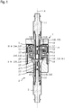
- the device according to the invention comprises a first structural unit 1, which may be referred to as a rotor, and a second structural unit 2, which operates, for example, as a stator.
- the device is used for Transmission of high-speed optical signals between the first unit 1 and the second unit 2, wherein the first unit 1 and the second unit 2 are rotatable relative to each other about an axis A.
- the second unit 2 is mounted relative to the first unit 1 by means of a bearing 3.
- the bearing 3 is configured as two roller bearings, each comprising a first bearing ring 1.3 (inner ring), a second bearing ring 2.3 (outer ring) and rolling elements 3.3, for example, balls.
- a first clamping sleeve 1.5 is initially provided.
- the first clamping sleeve 1.5 has a conical surface 1.51, a thread 1.53 and three slots 1.52 (FIG. FIG. 2 ) on.
- the slots 1.52 are located at that end of the first clamping sleeve 1.5, which is the thread 1.53 axially opposite, in particular, the slots run through the conical surface 1.51 1.51.
- the conical surface 1.51 of the first clamping sleeve 1.5 is convex, so arched outwards.
- the first clamping sleeve 1.5 comprises a cone.
- a sleeve 1.4 is mounted, which also has a conical surface 1.41, wherein the conical surface is 1.41 concave, that is curved inward.
- the two first bearing rings 1.3 of the bearing 3 are pushed or pressed, so that the slots 1.52 parallel to the axis A.
- a first body 1.6 which has an external thread 1.61, a machined contact surface 1.62 and another thread 1.63 (here an internal thread) provided.
- the (non-conical) end portion, so the thread 1.53, the first clamping sleeve 1.5 is screwed into the further thread 1.63 of the first body 1.6.
- first light guide 1.1 and a so-called first guide sleeve 1.7 and a first lens 1.2 are provided.
- the first lens 1.2 is used for collimation and is designed in the presented embodiment as a transparent spherical body, in particular as a quartz glass ball.
- the guide sleeve 1.7 is here made of a ceramic material and has a running in the direction of the axis A slot 1.71.
- the first lens 1.2 is inserted into the first guide sleeve 1.7. Thereafter, the first guide sleeve 1.7 is pushed with the first lens 1.2 on the end of the first light guide 1.1. The guide sleeve 1.7 together with the first lens 1.2 and the first light guide 1.1 is then inserted through the bore of the first body 1.6 into the first clamping sleeve 1.5.
- a union nut not shown in the figures is screwed to the thread 1.61, so that the first light guide 1.1 is axially fixed to the first body 1.6, wherein in addition by a positive coding a rotation of the first light guide 1.1 is made relative to the first body 1.6.
- the first lens 1.2 is thus by means of the first collet 1.5 on the first bearing ring 1.3 by a first conical connection I under contact of the conical surface of the first collet 1.51 1.51 and the conical surface of the sleeve 1.4 1.4, the radially between the first collet 1.5 and the first bearing ring 1.3 is arranged centrally with respect to the axis A.
- the first lens 1.2 is clamped by the first clamping sleeve 1.5 via the first guide sleeve 1.7. Consequently, the end of the first light guide 1.1 is centered with respect to the axis A.
- the first conical connection I is made under axial tensile load of the first clamping sleeve 1.5.
- the second structural unit 2 which acts as a stator here, includes, inter alia, a second clamping sleeve 2.5, which likewise has a conical surface 2.51 and slots 2.52 (FIG. FIG. 3 ) having.
- the conical surface 2.51 of the second Clamping sleeve 2.5 is convex, ie arched outwards.
- the second clamping sleeve 2.5 comprises a cone.
- a radial compliance of the clamping sleeve 2.5 is achieved in the region of the cone or the conical surface 2.51.
- a 2.53 thread is incorporated in the second clamping sleeve 2.5 at one end.
- the second clamping sleeve 2.5 is introduced in the course of assembly of the second unit 2 in a bore of a second body 2.4, wherein the bore in the second body 2.4 has a first conical surface 2.41.
- This first conical surface 2.41 is concave, ie curved inwards.
- a second light guide 2.1 and a so-called second guide sleeve 2.7 and a second lens 2.2 are provided.
- the second lens 2.2 is used for collimation and is designed here as a transparent spherical body, in particular as a quartz glass ball.
- the guide sleeve 2.7 is also made of a ceramic material and has a running in the direction of the axis A slot 2.71.
- the second lens 2.2 is inserted into the second guide sleeve 2.7. Thereafter, the second guide sleeve 2.7 is pushed with the second lens 2.2 on the end of the second light guide 2.1.
- the guide sleeve 2.7 including the second lens 2.2 and the second light guide 2.1 is then inserted through a central bore of the fastener 2.8 in the second clamping sleeve 2.5.
- the thread 2.83 of the fastener 2.8 is brought into engagement with the thread 2.53 of the second clamping sleeve 2.5, which projects axially out of the second body 2.4.
- the fastener 2.8 is screwed to the thread 2.53 of the second clamping sleeve 2.5, so that the fastener 2.8 is supported on the front side of the second body 2.4 and the second light guide 2.1 is fixed relative to the second body 2.4, wherein also by a positive coding a rotation of the second light guide 2.1 is made relative to the second clamping sleeve 2.5.
- the second clamping sleeve 2.5 is pulled into the first conical surface of the second body 2.4 2.4 2.4, causing a radial clamping of the second guide sleeve 2.7 together with the second lens 2.2.
- the first conical surface is 2.41 of the second body 2.4 in contact with the conical surface of the second clamping sleeve 2.51 2.5, whereby a second conical connection II is made.
- the second lens 2.2 is set centrically with respect to the axis A with the aid of the second clamping sleeve 2.5 on the second body 2.4.
- the second lens 2.2 is clamped by the second clamping sleeve 2.5 via the second guide sleeve 2.7.
- the second conical connection II is therefore made under axial tensile load of the second clamping sleeve 2.5.
- the second body 2.4 has according to FIG. 3 in addition, a thread 2.43 (here an external thread) and a second conical surface 2.44, which is curved outwards or convex.
- the second body 2.4 slots 2.42 which extend over a partial length of the second body 2.4 in the axial direction and are open at one end of the second body 2.4 in the axial direction, so that the second body 2.4 in this area radially yielding or is designed radially elastic.
- a clamping element 2.6 is pushed on the second body 2.4.
- This has a concave inwardly curved conical surface 2.61 and a thread 2.63 (here an internal thread).
- the thread 2.63 of the clamping element 2.6 is screwed to the thread 2.43 of the second body 2.4, wherein the resulting axial displacement of the clamping element 2.6 relative to the second body 2.4 second conical surface of the second body 2.4 2.4 2.4 in touching contact with the conical surface of the clamping element 2.61 2.6 arrives.
- the second body 2.4 deforms radially inward in the region of the slots 2.42.
- the clamping element 2.6 according to the embodiment may also be referred to as a union nut.
- the first unit 1 can now be connected to the second unit 2.
- the clamping element 2.6 is brought into a position in which the second conical surface 2.44 of the second body 2.4 and the conical surface 2.61 of the clamping element 2.6 do not touch, so that the second body 2.4 is mechanically mechanically tension-free in the region of its slots 2.42 .
- the first structural unit 1 is now introduced into the second structural unit 2, wherein the second bearing rings 2.3 (which are assigned to the second structural unit 2) are radially opposite the second body 2.4 or its slots 2.42.
- FIG. 4 Fig. 3 is a longitudinal section through an optical signal transmitting apparatus according to a second embodiment.
- the device according to the second embodiment differs from that according to the first embodiment in particular in that the bearing 3 'comprises two first bearing rings 1.3', each having a first conical surface 2.31 'and two second bearing rings 2.3', each having a second conical Surface 2.31 'exhibit.
- clamping element 2.6 'according to the second embodiment is designed as a ring with two inner conical surfaces 2.61'.
- the clamping element 2.6 'according to the second embodiment is radial designed resilient, in particular, the ring has a gap here, which allows a radial deformation of the ring or of the clamping element 2.6 '.
- the second body 2.4 ' is designed in the presented embodiment so that it has only a first conical surface 2.41', which is also concave, ie curved inwards.
- the first lens 1.2 is here with the help of the first clamping sleeve 1.5 on the first bearing ring 1.3 by a first conical connection I 'under contact of the conical surface 1.51 of the first clamping sleeve 1.5 and the conical surface 1.31' of the first bearing ring 1.3 'centric with respect to the axis A. , In this case, the first lens 1.2 is clamped by the first clamping sleeve 1.5 via the first guide sleeve 1.7.
- a device which is suitable for transmitting optical signals between two units 1, 2, wherein the first light guide 1.1, the first lens 1.2, the second light guide 2.1 and the second lens 2.2 with relatively little installation effort with high precision coaxial with each other are arranged.
- the first light guide 1.1, the first lens 1.2, the second light guide 2.1 and the second lens 2.2 with relatively little installation effort with high precision coaxial with each other are arranged.
Landscapes
- Physics & Mathematics (AREA)
- Engineering & Computer Science (AREA)
- General Engineering & Computer Science (AREA)
- General Physics & Mathematics (AREA)
- Optics & Photonics (AREA)
- Mechanical Engineering (AREA)
- Optical Couplings Of Light Guides (AREA)
- Rolling Contact Bearings (AREA)
Priority Applications (4)
| Application Number | Priority Date | Filing Date | Title |
|---|---|---|---|
| EP18172688.6A EP3570084B1 (fr) | 2018-05-16 | 2018-05-16 | Dispositif de transmission de signaux optiques entre deux unités structurales rotatives |
| DE102019203030.0A DE102019203030A1 (de) | 2018-05-16 | 2019-03-06 | Vorrichtung zum Übertragen von optischen Signalen zwischen zwei drehbaren Baueinheiten |
| US16/409,465 US10895693B2 (en) | 2018-05-16 | 2019-05-10 | Device for transmitting optical signals between two rotatable sub-assemblies |
| CN201910405757.1A CN110501785B (zh) | 2018-05-16 | 2019-05-15 | 在两个可旋转的结构单元之间传输光信号的装置 |
Applications Claiming Priority (1)
| Application Number | Priority Date | Filing Date | Title |
|---|---|---|---|
| EP18172688.6A EP3570084B1 (fr) | 2018-05-16 | 2018-05-16 | Dispositif de transmission de signaux optiques entre deux unités structurales rotatives |
Publications (2)
| Publication Number | Publication Date |
|---|---|
| EP3570084A1 true EP3570084A1 (fr) | 2019-11-20 |
| EP3570084B1 EP3570084B1 (fr) | 2020-07-08 |
Family
ID=62200268
Family Applications (1)
| Application Number | Title | Priority Date | Filing Date |
|---|---|---|---|
| EP18172688.6A Active EP3570084B1 (fr) | 2018-05-16 | 2018-05-16 | Dispositif de transmission de signaux optiques entre deux unités structurales rotatives |
Country Status (4)
| Country | Link |
|---|---|
| US (1) | US10895693B2 (fr) |
| EP (1) | EP3570084B1 (fr) |
| CN (1) | CN110501785B (fr) |
| DE (1) | DE102019203030A1 (fr) |
Cited By (2)
| Publication number | Priority date | Publication date | Assignee | Title |
|---|---|---|---|---|
| EP3633429B1 (fr) * | 2018-10-04 | 2021-12-08 | LTN Servotechnik GmbH | Dispositif de transmission de signaux optiques entre deux unités structurales rotatives |
| CN115173019A (zh) * | 2022-07-05 | 2022-10-11 | 成都西夏科技发展有限公司 | 波导加工设备 |
Families Citing this family (2)
| Publication number | Priority date | Publication date | Assignee | Title |
|---|---|---|---|---|
| US20210210270A1 (en) * | 2020-01-06 | 2021-07-08 | Kiryl Nikolaevich CHYKEYUK | Resonant rotating transformer |
| WO2021139867A1 (fr) * | 2020-01-06 | 2021-07-15 | ЧИКЕЮК, Кирилл | Module de connecteur rotatif pour dispositif de représentation |
Citations (5)
| Publication number | Priority date | Publication date | Assignee | Title |
|---|---|---|---|---|
| EP0107035A1 (fr) * | 1982-10-25 | 1984-05-02 | Litton Systems, Inc. | Joint rotatif pour alignement de fibres optiques à voie unique |
| US4848867A (en) * | 1988-02-10 | 1989-07-18 | Hitachi Cable Limited | Rotary joint for polarization plane maintaining optical fibers |
| US4872737A (en) * | 1988-09-07 | 1989-10-10 | Hitachi Cable Limited | Multi-port fiberoptic rotary joint |
| EP1857847A1 (fr) | 2006-05-16 | 2007-11-21 | Schleifring und Apparatebau GmbH | Dispositif et procédé d'alignement d'un transmetteur optique rotatif |
| WO2012136645A1 (fr) | 2011-04-04 | 2012-10-11 | GAT Gesellschaft für Antriebstechnik mbH | Transmetteur optique de rotation et procédé et dispositif pour la fabrication dudit transmetteur optique de rotation |
Family Cites Families (6)
| Publication number | Priority date | Publication date | Assignee | Title |
|---|---|---|---|---|
| DK143620A (fr) * | 1974-06-20 | |||
| US4124272A (en) * | 1976-12-14 | 1978-11-07 | Westinghouse Electric Corp. | Rotary fiber optic waveguide coupling |
| US6950568B2 (en) * | 2002-02-14 | 2005-09-27 | Varian, Inc. | Fiber-optic channel selecting apparatus |
| JP2009130773A (ja) * | 2007-11-27 | 2009-06-11 | Chubu Nippon Maruco Kk | 非接触コネクタ |
| CN203881972U (zh) * | 2014-04-21 | 2014-10-15 | 九江精达检测技术有限公司 | 一种实现单路光纤旋转传输超小型精密装置 |
| DE102016116113A1 (de) * | 2016-08-30 | 2018-03-01 | Thyssenkrupp Ag | Lager und Verfahren zur Verschleißüberwachung und/oder Lastmessung |
-
2018
- 2018-05-16 EP EP18172688.6A patent/EP3570084B1/fr active Active
-
2019
- 2019-03-06 DE DE102019203030.0A patent/DE102019203030A1/de not_active Withdrawn
- 2019-05-10 US US16/409,465 patent/US10895693B2/en active Active
- 2019-05-15 CN CN201910405757.1A patent/CN110501785B/zh active Active
Patent Citations (5)
| Publication number | Priority date | Publication date | Assignee | Title |
|---|---|---|---|---|
| EP0107035A1 (fr) * | 1982-10-25 | 1984-05-02 | Litton Systems, Inc. | Joint rotatif pour alignement de fibres optiques à voie unique |
| US4848867A (en) * | 1988-02-10 | 1989-07-18 | Hitachi Cable Limited | Rotary joint for polarization plane maintaining optical fibers |
| US4872737A (en) * | 1988-09-07 | 1989-10-10 | Hitachi Cable Limited | Multi-port fiberoptic rotary joint |
| EP1857847A1 (fr) | 2006-05-16 | 2007-11-21 | Schleifring und Apparatebau GmbH | Dispositif et procédé d'alignement d'un transmetteur optique rotatif |
| WO2012136645A1 (fr) | 2011-04-04 | 2012-10-11 | GAT Gesellschaft für Antriebstechnik mbH | Transmetteur optique de rotation et procédé et dispositif pour la fabrication dudit transmetteur optique de rotation |
Cited By (3)
| Publication number | Priority date | Publication date | Assignee | Title |
|---|---|---|---|---|
| EP3633429B1 (fr) * | 2018-10-04 | 2021-12-08 | LTN Servotechnik GmbH | Dispositif de transmission de signaux optiques entre deux unités structurales rotatives |
| CN115173019A (zh) * | 2022-07-05 | 2022-10-11 | 成都西夏科技发展有限公司 | 波导加工设备 |
| CN115173019B (zh) * | 2022-07-05 | 2024-05-17 | 成都西夏科技发展有限公司 | 波导加工设备 |
Also Published As
| Publication number | Publication date |
|---|---|
| CN110501785A (zh) | 2019-11-26 |
| US10895693B2 (en) | 2021-01-19 |
| CN110501785B (zh) | 2022-07-15 |
| US20190353849A1 (en) | 2019-11-21 |
| EP3570084B1 (fr) | 2020-07-08 |
| DE102019203030A1 (de) | 2019-11-21 |
Similar Documents
| Publication | Publication Date | Title |
|---|---|---|
| EP3570084B1 (fr) | Dispositif de transmission de signaux optiques entre deux unités structurales rotatives | |
| DE69636186T2 (de) | Vorrichtung mit einer Linse zum optischen Verbinden eines optischen Elements, zum Beispiel einer optischen Faser, mit einem anderen optischen Element | |
| WO2018184708A1 (fr) | Collimateur à fibres réglable | |
| DE202015008601U1 (de) | Spannvorrichtung für Werkstücke | |
| EP2736665B1 (fr) | Dispositif de serrage pour machine d'équilibrage | |
| EP1575739A1 (fr) | Dispositif et procede de serrage centre de pieces destinees a etre entrainees par rotation | |
| EP1332394B1 (fr) | Couplage de guides d'ondes optiques | |
| DE102015218516B4 (de) | Vorrichtung und Verfahren zum automatischen Auswuchten von Bohrköpfen | |
| EP4051918A1 (fr) | Banc d'essai | |
| EP2730686B1 (fr) | Rotor de filage à extrémité ouverte | |
| DE102014102220B3 (de) | Verfahren zum Herstellen einer Linsenfassung und eine in einem Tubus radial fixierbare Linsenfassung | |
| DE102013109605B3 (de) | Optische Baugruppe mit einer monolithischen Fassung mit in einer gleichen Richtung wirkenden Stellschrauben | |
| DE102019121755A1 (de) | Mehrteiliges Stellelement | |
| WO2012136645A1 (fr) | Transmetteur optique de rotation et procédé et dispositif pour la fabrication dudit transmetteur optique de rotation | |
| DE102020004419B4 (de) | Drehbewegung-Erfassungsvorrichtung | |
| EP2905582A1 (fr) | Dispositif de mesure d'angle prémonté | |
| DE102014106328B4 (de) | Verfahren zum Herstellen eines Halters für ein Werkzeug und/oder ein Werkstück sowie entsprechender Halter | |
| DE2923892C2 (fr) | ||
| DE102015101387B3 (de) | Optische Fassung mit wenigstens einer Klemmeinheit mit einer Membranfeder | |
| DE19512705A1 (de) | Befestigungsvorrichtung für eine Schleifscheibe | |
| DE102019115501B4 (de) | Spindel für einen Gewindetrieb und Gewindetrieb mit derselben | |
| EP3633429B1 (fr) | Dispositif de transmission de signaux optiques entre deux unités structurales rotatives | |
| DE202019103788U1 (de) | Rotierbares Verbindungsstück für eine Glasfaser | |
| DE4312843A1 (de) | Zugkraftmeßeinrichtung | |
| DE102018106011B3 (de) | Linsenfassung mit Exzenter |
Legal Events
| Date | Code | Title | Description |
|---|---|---|---|
| STAA | Information on the status of an ep patent application or granted ep patent |
Free format text: STATUS: EXAMINATION IS IN PROGRESS |
|
| PUAI | Public reference made under article 153(3) epc to a published international application that has entered the european phase |
Free format text: ORIGINAL CODE: 0009012 |
|
| 17P | Request for examination filed |
Effective date: 20180516 |
|
| AK | Designated contracting states |
Kind code of ref document: A1 Designated state(s): AL AT BE BG CH CY CZ DE DK EE ES FI FR GB GR HR HU IE IS IT LI LT LU LV MC MK MT NL NO PL PT RO RS SE SI SK SM TR |
|
| AX | Request for extension of the european patent |
Extension state: BA ME |
|
| GRAP | Despatch of communication of intention to grant a patent |
Free format text: ORIGINAL CODE: EPIDOSNIGR1 |
|
| STAA | Information on the status of an ep patent application or granted ep patent |
Free format text: STATUS: GRANT OF PATENT IS INTENDED |
|
| INTG | Intention to grant announced |
Effective date: 20200206 |
|
| GRAS | Grant fee paid |
Free format text: ORIGINAL CODE: EPIDOSNIGR3 |
|
| GRAA | (expected) grant |
Free format text: ORIGINAL CODE: 0009210 |
|
| STAA | Information on the status of an ep patent application or granted ep patent |
Free format text: STATUS: THE PATENT HAS BEEN GRANTED |
|
| RBV | Designated contracting states (corrected) |
Designated state(s): AL AT BE BG CH CY CZ DE DK EE ES FI FR GB GR HR HU IE IS IT LI LT LU LV MC MK MT NL NO PL PT RO RS SE SI SK SM TR |
|
| AK | Designated contracting states |
Kind code of ref document: B1 Designated state(s): AL AT BE BG CH CY CZ DE DK EE ES FI FR GB GR HR HU IE IS IT LI LT LU LV MC MK MT NL NO PL PT RO RS SE SI SK SM TR |
|
| REG | Reference to a national code |
Ref country code: CH Ref legal event code: EP Ref country code: AT Ref legal event code: REF Ref document number: 1289067 Country of ref document: AT Kind code of ref document: T Effective date: 20200715 |
|
| REG | Reference to a national code |
Ref country code: DE Ref legal event code: R096 Ref document number: 502018001830 Country of ref document: DE |
|
| REG | Reference to a national code |
Ref country code: IE Ref legal event code: FG4D Free format text: LANGUAGE OF EP DOCUMENT: GERMAN |
|
| REG | Reference to a national code |
Ref country code: CH Ref legal event code: NV Representative=s name: ICB INGENIEURS CONSEILS EN BREVETS SA, CH |
|
| REG | Reference to a national code |
Ref country code: LT Ref legal event code: MG4D |
|
| REG | Reference to a national code |
Ref country code: NL Ref legal event code: MP Effective date: 20200708 |
|
| PG25 | Lapsed in a contracting state [announced via postgrant information from national office to epo] |
Ref country code: ES Free format text: LAPSE BECAUSE OF FAILURE TO SUBMIT A TRANSLATION OF THE DESCRIPTION OR TO PAY THE FEE WITHIN THE PRESCRIBED TIME-LIMIT Effective date: 20200708 Ref country code: BG Free format text: LAPSE BECAUSE OF FAILURE TO SUBMIT A TRANSLATION OF THE DESCRIPTION OR TO PAY THE FEE WITHIN THE PRESCRIBED TIME-LIMIT Effective date: 20201008 Ref country code: SE Free format text: LAPSE BECAUSE OF FAILURE TO SUBMIT A TRANSLATION OF THE DESCRIPTION OR TO PAY THE FEE WITHIN THE PRESCRIBED TIME-LIMIT Effective date: 20200708 Ref country code: HR Free format text: LAPSE BECAUSE OF FAILURE TO SUBMIT A TRANSLATION OF THE DESCRIPTION OR TO PAY THE FEE WITHIN THE PRESCRIBED TIME-LIMIT Effective date: 20200708 Ref country code: LT Free format text: LAPSE BECAUSE OF FAILURE TO SUBMIT A TRANSLATION OF THE DESCRIPTION OR TO PAY THE FEE WITHIN THE PRESCRIBED TIME-LIMIT Effective date: 20200708 Ref country code: PT Free format text: LAPSE BECAUSE OF FAILURE TO SUBMIT A TRANSLATION OF THE DESCRIPTION OR TO PAY THE FEE WITHIN THE PRESCRIBED TIME-LIMIT Effective date: 20201109 Ref country code: FI Free format text: LAPSE BECAUSE OF FAILURE TO SUBMIT A TRANSLATION OF THE DESCRIPTION OR TO PAY THE FEE WITHIN THE PRESCRIBED TIME-LIMIT Effective date: 20200708 Ref country code: GR Free format text: LAPSE BECAUSE OF FAILURE TO SUBMIT A TRANSLATION OF THE DESCRIPTION OR TO PAY THE FEE WITHIN THE PRESCRIBED TIME-LIMIT Effective date: 20201009 Ref country code: NO Free format text: LAPSE BECAUSE OF FAILURE TO SUBMIT A TRANSLATION OF THE DESCRIPTION OR TO PAY THE FEE WITHIN THE PRESCRIBED TIME-LIMIT Effective date: 20201008 |
|
| PG25 | Lapsed in a contracting state [announced via postgrant information from national office to epo] |
Ref country code: PL Free format text: LAPSE BECAUSE OF FAILURE TO SUBMIT A TRANSLATION OF THE DESCRIPTION OR TO PAY THE FEE WITHIN THE PRESCRIBED TIME-LIMIT Effective date: 20200708 Ref country code: RS Free format text: LAPSE BECAUSE OF FAILURE TO SUBMIT A TRANSLATION OF THE DESCRIPTION OR TO PAY THE FEE WITHIN THE PRESCRIBED TIME-LIMIT Effective date: 20200708 Ref country code: LV Free format text: LAPSE BECAUSE OF FAILURE TO SUBMIT A TRANSLATION OF THE DESCRIPTION OR TO PAY THE FEE WITHIN THE PRESCRIBED TIME-LIMIT Effective date: 20200708 Ref country code: IS Free format text: LAPSE BECAUSE OF FAILURE TO SUBMIT A TRANSLATION OF THE DESCRIPTION OR TO PAY THE FEE WITHIN THE PRESCRIBED TIME-LIMIT Effective date: 20201108 |
|
| PG25 | Lapsed in a contracting state [announced via postgrant information from national office to epo] |
Ref country code: NL Free format text: LAPSE BECAUSE OF FAILURE TO SUBMIT A TRANSLATION OF THE DESCRIPTION OR TO PAY THE FEE WITHIN THE PRESCRIBED TIME-LIMIT Effective date: 20200708 |
|
| REG | Reference to a national code |
Ref country code: DE Ref legal event code: R097 Ref document number: 502018001830 Country of ref document: DE |
|
| PG25 | Lapsed in a contracting state [announced via postgrant information from national office to epo] |
Ref country code: DK Free format text: LAPSE BECAUSE OF FAILURE TO SUBMIT A TRANSLATION OF THE DESCRIPTION OR TO PAY THE FEE WITHIN THE PRESCRIBED TIME-LIMIT Effective date: 20200708 Ref country code: CZ Free format text: LAPSE BECAUSE OF FAILURE TO SUBMIT A TRANSLATION OF THE DESCRIPTION OR TO PAY THE FEE WITHIN THE PRESCRIBED TIME-LIMIT Effective date: 20200708 Ref country code: RO Free format text: LAPSE BECAUSE OF FAILURE TO SUBMIT A TRANSLATION OF THE DESCRIPTION OR TO PAY THE FEE WITHIN THE PRESCRIBED TIME-LIMIT Effective date: 20200708 Ref country code: EE Free format text: LAPSE BECAUSE OF FAILURE TO SUBMIT A TRANSLATION OF THE DESCRIPTION OR TO PAY THE FEE WITHIN THE PRESCRIBED TIME-LIMIT Effective date: 20200708 Ref country code: SM Free format text: LAPSE BECAUSE OF FAILURE TO SUBMIT A TRANSLATION OF THE DESCRIPTION OR TO PAY THE FEE WITHIN THE PRESCRIBED TIME-LIMIT Effective date: 20200708 |
|
| PLBE | No opposition filed within time limit |
Free format text: ORIGINAL CODE: 0009261 |
|
| STAA | Information on the status of an ep patent application or granted ep patent |
Free format text: STATUS: NO OPPOSITION FILED WITHIN TIME LIMIT |
|
| PG25 | Lapsed in a contracting state [announced via postgrant information from national office to epo] |
Ref country code: AL Free format text: LAPSE BECAUSE OF FAILURE TO SUBMIT A TRANSLATION OF THE DESCRIPTION OR TO PAY THE FEE WITHIN THE PRESCRIBED TIME-LIMIT Effective date: 20200708 |
|
| 26N | No opposition filed |
Effective date: 20210409 |
|
| PG25 | Lapsed in a contracting state [announced via postgrant information from national office to epo] |
Ref country code: SK Free format text: LAPSE BECAUSE OF FAILURE TO SUBMIT A TRANSLATION OF THE DESCRIPTION OR TO PAY THE FEE WITHIN THE PRESCRIBED TIME-LIMIT Effective date: 20200708 |
|
| PG25 | Lapsed in a contracting state [announced via postgrant information from national office to epo] |
Ref country code: MC Free format text: LAPSE BECAUSE OF FAILURE TO SUBMIT A TRANSLATION OF THE DESCRIPTION OR TO PAY THE FEE WITHIN THE PRESCRIBED TIME-LIMIT Effective date: 20200708 Ref country code: LU Free format text: LAPSE BECAUSE OF NON-PAYMENT OF DUE FEES Effective date: 20210516 |
|
| REG | Reference to a national code |
Ref country code: BE Ref legal event code: MM Effective date: 20210531 |
|
| PG25 | Lapsed in a contracting state [announced via postgrant information from national office to epo] |
Ref country code: IE Free format text: LAPSE BECAUSE OF NON-PAYMENT OF DUE FEES Effective date: 20210516 |
|
| PG25 | Lapsed in a contracting state [announced via postgrant information from national office to epo] |
Ref country code: BE Free format text: LAPSE BECAUSE OF NON-PAYMENT OF DUE FEES Effective date: 20210531 |
|
| PG25 | Lapsed in a contracting state [announced via postgrant information from national office to epo] |
Ref country code: CY Free format text: LAPSE BECAUSE OF FAILURE TO SUBMIT A TRANSLATION OF THE DESCRIPTION OR TO PAY THE FEE WITHIN THE PRESCRIBED TIME-LIMIT Effective date: 20200708 |
|
| PG25 | Lapsed in a contracting state [announced via postgrant information from national office to epo] |
Ref country code: HU Free format text: LAPSE BECAUSE OF FAILURE TO SUBMIT A TRANSLATION OF THE DESCRIPTION OR TO PAY THE FEE WITHIN THE PRESCRIBED TIME-LIMIT; INVALID AB INITIO Effective date: 20180516 |
|
| PG25 | Lapsed in a contracting state [announced via postgrant information from national office to epo] |
Ref country code: SI Free format text: LAPSE BECAUSE OF FAILURE TO SUBMIT A TRANSLATION OF THE DESCRIPTION OR TO PAY THE FEE WITHIN THE PRESCRIBED TIME-LIMIT Effective date: 20200708 |
|
| PG25 | Lapsed in a contracting state [announced via postgrant information from national office to epo] |
Ref country code: MK Free format text: LAPSE BECAUSE OF FAILURE TO SUBMIT A TRANSLATION OF THE DESCRIPTION OR TO PAY THE FEE WITHIN THE PRESCRIBED TIME-LIMIT Effective date: 20200708 |
|
| PG25 | Lapsed in a contracting state [announced via postgrant information from national office to epo] |
Ref country code: TR Free format text: LAPSE BECAUSE OF FAILURE TO SUBMIT A TRANSLATION OF THE DESCRIPTION OR TO PAY THE FEE WITHIN THE PRESCRIBED TIME-LIMIT Effective date: 20200708 |
|
| REG | Reference to a national code |
Ref country code: AT Ref legal event code: MM01 Ref document number: 1289067 Country of ref document: AT Kind code of ref document: T Effective date: 20230516 |
|
| PG25 | Lapsed in a contracting state [announced via postgrant information from national office to epo] |
Ref country code: AT Free format text: LAPSE BECAUSE OF NON-PAYMENT OF DUE FEES Effective date: 20230516 |
|
| PG25 | Lapsed in a contracting state [announced via postgrant information from national office to epo] |
Ref country code: AT Free format text: LAPSE BECAUSE OF NON-PAYMENT OF DUE FEES Effective date: 20230516 |
|
| PG25 | Lapsed in a contracting state [announced via postgrant information from national office to epo] |
Ref country code: MT Free format text: LAPSE BECAUSE OF FAILURE TO SUBMIT A TRANSLATION OF THE DESCRIPTION OR TO PAY THE FEE WITHIN THE PRESCRIBED TIME-LIMIT Effective date: 20200708 |
|
| PGFP | Annual fee paid to national office [announced via postgrant information from national office to epo] |
Ref country code: DE Payment date: 20250521 Year of fee payment: 8 |
|
| PGFP | Annual fee paid to national office [announced via postgrant information from national office to epo] |
Ref country code: GB Payment date: 20250527 Year of fee payment: 8 |
|
| PGFP | Annual fee paid to national office [announced via postgrant information from national office to epo] |
Ref country code: IT Payment date: 20250527 Year of fee payment: 8 |
|
| PGFP | Annual fee paid to national office [announced via postgrant information from national office to epo] |
Ref country code: FR Payment date: 20250528 Year of fee payment: 8 |
|
| PGFP | Annual fee paid to national office [announced via postgrant information from national office to epo] |
Ref country code: CH Payment date: 20250601 Year of fee payment: 8 |
|
| REG | Reference to a national code |
Ref country code: CH Ref legal event code: R17 Free format text: ST27 STATUS EVENT CODE: U-0-0-R10-R17 (AS PROVIDED BY THE NATIONAL OFFICE) Effective date: 20260108 |
|
| PGFP | Annual fee paid to national office [announced via postgrant information from national office to epo] |
Ref country code: AT Payment date: 20260410 Year of fee payment: 5 |