EP3570102A1 - Method for applying driving voltage for liquid lens, liquid lens, camera module, and optical instrument - Google Patents
Method for applying driving voltage for liquid lens, liquid lens, camera module, and optical instrument Download PDFInfo
- Publication number
- EP3570102A1 EP3570102A1 EP18738775.8A EP18738775A EP3570102A1 EP 3570102 A1 EP3570102 A1 EP 3570102A1 EP 18738775 A EP18738775 A EP 18738775A EP 3570102 A1 EP3570102 A1 EP 3570102A1
- Authority
- EP
- European Patent Office
- Prior art keywords
- voltage
- driving
- electrode
- sub
- cycle
- Prior art date
- Legal status (The legal status is an assumption and is not a legal conclusion. Google has not performed a legal analysis and makes no representation as to the accuracy of the status listed.)
- Granted
Links
Images




Classifications
-
- G—PHYSICS
- G03—PHOTOGRAPHY; CINEMATOGRAPHY; ANALOGOUS TECHNIQUES USING WAVES OTHER THAN OPTICAL WAVES; ELECTROGRAPHY; HOLOGRAPHY
- G03B—APPARATUS OR ARRANGEMENTS FOR TAKING PHOTOGRAPHS OR FOR PROJECTING OR VIEWING THEM; APPARATUS OR ARRANGEMENTS EMPLOYING ANALOGOUS TECHNIQUES USING WAVES OTHER THAN OPTICAL WAVES; ACCESSORIES THEREFOR
- G03B13/00—Viewfinders; Focusing aids for cameras; Means for focusing for cameras; Autofocus systems for cameras
- G03B13/32—Means for focusing
- G03B13/34—Power focusing
- G03B13/36—Autofocus systems
-
- G—PHYSICS
- G02—OPTICS
- G02B—OPTICAL ELEMENTS, SYSTEMS OR APPARATUS
- G02B26/00—Optical devices or arrangements for the control of light using movable or deformable optical elements
- G02B26/004—Optical devices or arrangements for the control of light using movable or deformable optical elements based on a displacement or a deformation of a fluid
-
- G—PHYSICS
- G02—OPTICS
- G02B—OPTICAL ELEMENTS, SYSTEMS OR APPARATUS
- G02B3/00—Simple or compound lenses
- G02B3/12—Fluid-filled or evacuated lenses
- G02B3/14—Fluid-filled or evacuated lenses of variable focal length
-
- G—PHYSICS
- G03—PHOTOGRAPHY; CINEMATOGRAPHY; ANALOGOUS TECHNIQUES USING WAVES OTHER THAN OPTICAL WAVES; ELECTROGRAPHY; HOLOGRAPHY
- G03B—APPARATUS OR ARRANGEMENTS FOR TAKING PHOTOGRAPHS OR FOR PROJECTING OR VIEWING THEM; APPARATUS OR ARRANGEMENTS EMPLOYING ANALOGOUS TECHNIQUES USING WAVES OTHER THAN OPTICAL WAVES; ACCESSORIES THEREFOR
- G03B13/00—Viewfinders; Focusing aids for cameras; Means for focusing for cameras; Autofocus systems for cameras
- G03B13/32—Means for focusing
-
- G—PHYSICS
- G03—PHOTOGRAPHY; CINEMATOGRAPHY; ANALOGOUS TECHNIQUES USING WAVES OTHER THAN OPTICAL WAVES; ELECTROGRAPHY; HOLOGRAPHY
- G03B—APPARATUS OR ARRANGEMENTS FOR TAKING PHOTOGRAPHS OR FOR PROJECTING OR VIEWING THEM; APPARATUS OR ARRANGEMENTS EMPLOYING ANALOGOUS TECHNIQUES USING WAVES OTHER THAN OPTICAL WAVES; ACCESSORIES THEREFOR
- G03B17/00—Details of cameras or camera bodies; Accessories therefor
- G03B17/02—Bodies
- G03B17/12—Bodies with means for supporting objectives, supplementary lenses, filters, masks, or turrets
-
- H—ELECTRICITY
- H04—ELECTRIC COMMUNICATION TECHNIQUE
- H04N—PICTORIAL COMMUNICATION, e.g. TELEVISION
- H04N23/00—Cameras or camera modules comprising electronic image sensors; Control thereof
-
- H—ELECTRICITY
- H04—ELECTRIC COMMUNICATION TECHNIQUE
- H04N—PICTORIAL COMMUNICATION, e.g. TELEVISION
- H04N23/00—Cameras or camera modules comprising electronic image sensors; Control thereof
- H04N23/60—Control of cameras or camera modules
-
- G—PHYSICS
- G02—OPTICS
- G02B—OPTICAL ELEMENTS, SYSTEMS OR APPARATUS
- G02B27/00—Optical systems or apparatus not provided for by any of the groups G02B1/00 - G02B26/00, G02B30/00
- G02B27/64—Imaging systems using optical elements for stabilisation of the lateral and angular position of the image
- G02B27/646—Imaging systems using optical elements for stabilisation of the lateral and angular position of the image compensating for small deviations, e.g. due to vibration or shake
Definitions
- the liquid lens 300 may include a cavity 310 formed therein.
- the cavity 310 may be a region that light that has passed through the first lens unit 100 penetrates, and may include a liquid in at least a portion thereof.
- two kinds of liquid i.e. a conductive liquid and a non-conductive liquid (or an insulation liquid)
- a conductive liquid and a non-conductive liquid may be included in the cavity 310, and the conductive liquid and the non-conductive liquid may form an interface therebetween without being mixed with each other.
- the interface between the conductive liquid and the non-conductive liquid may be deformed by a driving voltage applied thereto through the connection unit 500, whereby the curvature of the interface of the liquid lens 300 and/or the focal length of the liquid lens may be changed.
- the control circuit 210 may include a control unit 220.
- the control unit 220 is a part for performing an AF function and an OIS function.
- the control unit 220 may control the liquid lens module 260 included in the lens assembly 250 in response to a user request or using a sensing result (e.g. a motion signal of a gyro sensor 225, etc.).
- the controller 230 may receive information (i.e. information about the distance to an object) for performing an AF function from the inside (e.g. an image sensor) or the outside (e.g. a distance sensor) of the optical device or the camera module 200, and may calculate a driving voltage corresponding to the shape that the liquid lens 280 needs to have in accordance with the focal length for focusing the lens on the object using the distance information.
- information i.e. information about the distance to an object
- the inside e.g. an image sensor
- the outside e.g. a distance sensor
- the voltage driver 235 may receive a digital-type driving voltage code from the controller 230, may generate an analog-type driving voltage corresponding to the received driving voltage code, and may provide the analog-type driving voltage to the lens assembly 250.
- the voltage driver 235 may include a voltage booster for receiving a supply voltage (e.g. voltage supplied from a separate power supply circuit) and increasing a voltage level, a voltage stabilizer for stabilizing the output of the voltage booster, and a switching unit for selectively supplying the output of the voltage booster to respective terminals of the liquid lens 280.
- a supply voltage e.g. voltage supplied from a separate power supply circuit
- a voltage stabilizer for stabilizing the output of the voltage booster
- a switching unit for selectively supplying the output of the voltage booster to respective terminals of the liquid lens 280.
- the first voltage V may be applied to the first driving electrode in all of the sub-cycles SUB1 to SUB4.
- the first driving voltage applied to the first driving electrode in the initial cycle CYCLE0 corresponds to V.
- the average voltage applied to the first to fourth driving electrodes in the initial cycle CYCLE0 is V
- the average voltage applied to the first to fourth driving electrodes in the first cycle CYCLE1 is V + dv / 4
- the average voltage applied to the first to fourth driving electrodes in the second cycle CYCLE2 is V + dv / 2
- the average voltage applied to the first to fourth driving electrodes in the third cycle CYCLE3 is V + 3dv / 4
- the average voltage applied to the first to fourth driving electrodes in the fourth cycle CYCLE4 is V + dv.
- the unit voltage with respect to the driving voltage for determining the auto-focusing resolution is the same as the unit voltage of the voltage driver 235.
- the driving voltage of V + dv may be applied, and only one step may be performed.
- FIG. 9 is a view showing a method of applying a voltage to a liquid lens according to another embodiment in terms of one driving electrode.
- FIG. 9 shows a driving voltage applied to a driving electrode corresponding to the first electrode sector L1 in each cycle CYCLE0 to CYCLE6.
- FIG. 10 illustrates the average voltage applied to the electrode sectors in each cycle CYCLE0 to CYCLE6 shown in FIG. 9 .
- the second voltage may be the sum of the first voltage and a unit voltage of a voltage driver supplying a driving voltage to the liquid lens.
- the sum of the 1 st to n th driving voltages applied in each of the n sub-cycles may be maintained at a constant level.
- the second voltage may be the sum of the first voltage and a unit voltage of a voltage driver supplying a driving voltage to the liquid lens.
- an optical device (or an optical instrument) including a camera module, which includes the liquid lens described above, may be implemented.
- the optical device may include a device that may process or analyze optical signals.
- Examples of the optical device may include camera/video devices, telescopic devices, microscopic devices, an interferometer, a photometer, a polarimeter, a spectrometer, a reflectometer, an autocollimator, and a lens-meter, and the embodiments may be applied to optical devices that may include the liquid lens.
- the optical device may be implemented in a portable device such as, for example, a smart phone, a laptop computer, or a tablet computer.
Landscapes
- Physics & Mathematics (AREA)
- General Physics & Mathematics (AREA)
- Optics & Photonics (AREA)
- Engineering & Computer Science (AREA)
- Multimedia (AREA)
- Signal Processing (AREA)
- Lens Barrels (AREA)
- Mechanical Light Control Or Optical Switches (AREA)
- Adjustment Of Camera Lenses (AREA)
- Automatic Focus Adjustment (AREA)
- Studio Devices (AREA)
Abstract
Description
- The present disclosure relates to a method of applying a driving voltage to a liquid lens, a liquid lens, a camera module, and an optical device. More particularly, the present disclosure relates to a method of applying a driving voltage to a liquid lens enabling adjustment of a focal length using electrical energy, a liquid lens, a camera module, and an optical device.
- People who use portable devices demand optical devices that have high resolution, are small, and have various photographing functions (an optical zoom-in/zoom-out function, an auto-focusing (AF) function, a handshake compensation or optical image stabilization (OIS) function, etc.). Such photographing functions may be realized by directly moving a plurality of lenses that are combined. In the case in which the number of lenses is increased, however, the size of an optical device may be increased.
- The auto-focusing and handshake compensation functions are performed by tilting or moving a lens module including a plurality of lenses, which are fixed to a lens holder in the state in which the optical axes of the lens are aligned, along the optical axis or in a direction perpendicular to the optical axis. An additional lens moving apparatus is used to move the lens module. However, the lens moving apparatus has high power consumption, and an additional cover glass needs to be provided separately from the camera module in order to protect the lens moving apparatus, thus leading to an increase in the overall thickness of an optical device.
- Therefore, research has been conducted on a liquid lens configured to electrically adjust the curvature of an interface between two kinds of liquid in order to perform auto-focusing and handshake compensation functions.
- The present disclosure provides a method of applying a driving voltage to a liquid lens, which enables improvement of auto-focusing resolution without an increase in power consumption, a liquid lens, a camera module, and an optical device.
- However, the objects to be accomplished by the disclosure are not limited to the above-mentioned objects, and other objects not mentioned will be clearly understood by those skilled in the art from the following description.
- In one embodiment, a camera module may include a first plate including a cavity formed therein to accommodate a conductive liquid and a non-conductive liquid, an electrode unit disposed on the first plate and electrically connected to an external power source to change an interface between the conductive liquid and the non-conductive liquid, an insulation unit disposed on the electrode unit to prevent contact with the non-conductive liquid, and a control unit controlling a voltage applied to the electrode unit. The electrode unit may include a first electrode and a second electrode electromagnetically interacting with each other to change the interface between the conductive liquid and the non-conductive liquid, the first electrode may include a plurality of electrode sectors arranged sequentially in a clockwise direction with respect to an optical axis, and the control unit may perform control so as to apply voltages to driving electrodes corresponding to the electrode sectors by rotation in a clockwise direction or in a counterclockwise direction.
- Depending on the embodiment, the control unit may apply a first voltage to at least one of the driving electrodes, and may apply a second voltage, which has a different intensity from the first voltage, to remaining ones of the driving electrodes.
- Depending on the embodiment, the second voltage may be higher than the first voltage.
- In another embodiment, a method of applying a voltage to a liquid lens may include applying a first voltage to each of 1st to nth (n being an integer of 2 or greater) driving electrodes, applying a second voltage to m (m being an integer of 1 to n-1) driving electrodes of the 1st to nth driving electrodes and applying a first voltage to remaining n-m driving electrodes, and applying the second voltage to each of the 1st to nth driving electrodes. The applying the second voltage to m driving electrodes of the 1st to nth driving electrodes and applying the first voltage to remaining n-m driving electrodes may include applying m driving voltages as the second voltage by rotation.
- Depending on the embodiment, the second voltage may be the sum of the first voltage and a unit voltage of a voltage driver supplying a driving voltage to the liquid lens.
- Depending on the embodiment, in the applying m driving voltages of the 1st to nth driving voltages as the second voltage, n sub-cycles may be provided, and at least one of the 1st to nth driving voltages may be changed in adjacent ones of the n sub-cycles.
- In still another embodiment, a liquid lens may include a conductive liquid and a non-conductive liquid accommodated in a cavity so as to form an interface therebetween, and 1st to nth (n being an integer of 2 or greater) driving electrodes configured to control the interface. 1st to nth driving voltages respectively applied to the 1st to nth driving electrodes may be controlled in respective cycles, each of which includes n sub-cycles. In each of the n sub-cycles, at least one of the 1st to nth driving voltages may be applied as a first voltage, m (m being an integer of 1 to n-1) driving voltages of the 1st to nth driving voltages may be applied as a second voltage, and the m driving voltages may be applied as the second voltage by rotation.
- Depending on the embodiment, the second voltage may be the sum of the first voltage and a unit voltage of a voltage driver supplying a driving voltage to the liquid lens.
- Depending on the embodiment, any one of the 1st to nth driving voltages may be applied as the second voltage in the m sub-cycles.
- Depending on the embodiment, at least one of the 1st to nth driving voltages may be changed in adjacent ones of the n sub-cycles.
- Depending on the embodiment, the sum of the 1st to nth driving voltages applied in each of the n sub-cycles may be maintained at a constant level.
- In still another embodiment, an optical device may include the camera module described above, a display unit outputting an image, a battery supplying power to the camera module, and a housing in which the camera module, the display unit, and the battery are mounted.
- In still another embodiment, a liquid lens may include a conductive liquid and a non-conductive liquid accommodated in a cavity so as to form an interface therebetween, and n (n being an integer of 2 or greater) individual electrodes and a common electrode configured to control the interface. A first driving voltage, which is applied between the common electrode and any one of the n individual electrodes, may be controlled in respective unit cycles, each of which includes a first sub-cycle and a second sub-cycle. The level of the first driving voltage in the first sub-cycle may be a first voltage, and the level of the first driving voltage in the second sub-cycle may be a second voltage.
- Depending on the embodiment, the sum of the number of the first sub-cycles and the number of the second sub-cycles may be X (X being an integer of 2 or greater).
- Depending on the embodiment, in one unit cycle, the sum of the driving voltages applied between the n individual electrodes and the common electrode in each of the sub-cycles may be maintained at a constant level.
- Depending on the embodiment, if the number of the second sub-cycles of the X sub-cycles is Y in one unit cycle, the average driving voltage in the unit cycle may satisfy the following equation.


- Depending on the embodiment, when the process goes from the first sub-cycle to the second sub-cycle, which is adjacent to the first sub-cycle, the level of the driving voltage applied to at least one of the n individual electrodes may be changed.
- Depending on the embodiment, the second voltage may be the sum of the first voltage and the predetermined unit voltage.
- Depending on the embodiment, the first driving voltage may have two voltage levels.
- Depending on the embodiment, the second voltage may be higher than the first voltage.
- In still another embodiment, a camera module may include a liquid lens, which includes a conductive liquid and a non-conductive liquid accommodated in a cavity so as to form an interface therebetween and n (n being an integer of 2 or greater) individual electrodes and a common electrode configured to control the interface, and a control circuit controlling a voltage applied to the n individual electrodes and the common electrode. A first driving voltage, which is applied between the common electrode and any one of the n individual electrodes, may be controlled in respective unit cycles, each of which includes a first sub-cycle and a second sub-cycle. The level of the first driving voltage in the first sub-cycle may be a first voltage, and the level of the first driving voltage in the second sub-cycle may be a second voltage.
- In still another embodiment, an optical device may include a camera module, a display unit outputting an image, a battery supplying power to the camera module, and a housing in which the camera module, the display unit, and the battery are mounted.
- The above aspects of the present disclosure are only a part of the exemplary embodiments of the present disclosure, and various embodiments based on technical features of the present disclosure may be devised and understood by those skilled in the art from the following detailed description of the present disclosure.
- The effects of the device according to the present disclosure will be described below.
- According to a method of applying a driving voltage to a liquid lens, a liquid lens, a camera module, and an optical device according to an embodiment, it is possible to increase auto-focusing resolution using a unit voltage within a constant output voltage range of a voltage driver.
- In addition, an increase in the output voltage range of a voltage driver is not required while increasing auto-focusing resolution, thus leading to a reduction in the amount of power consumed by an optical device.
- However, the effects achievable through the disclosure are not limited to the above-mentioned effects, and other effects not mentioned will be clearly understood by those skilled in the art from the following description.
-
-
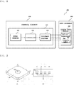
FIG. 1 shows an example of a camera module according to an embodiment. -
FIG. 2 shows an example of a lens assembly included in the camera module. -
FIG. 3 is a block diagram schematically showing the camera module shown inFIG. 1 . -
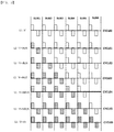
FIG. 4 shows a liquid lens, an interface of which is adjusted in response to a driving voltage. -
FIG. 5 is a view showing an example of a voltage supplied to both ends of a liquid lens. -
FIG. 6 is a view showing a method of applying a voltage to a liquid lens according to an embodiment. -
FIG. 7 is a view showing a method of applying a voltage to a liquid lens according to the embodiment shown inFIG. 6 in terms of one driving electrode. -
FIG. 8 is a view showing the effects of the driving voltage applying method according to the embodiment. -
FIG. 9 is a view showing a method of applying a voltage to a liquid lens according to another embodiment in terms of one driving electrode. -
FIG. 10 is a view showing the effects of the driving voltage applying method according to another embodiment. - A liquid lens according to a first embodiment may include a conductive liquid and a non-conductive liquid accommodated in a cavity so as to form an interface therebetween, and n (n being an integer of 2 or greater) individual electrodes and a common electrode configured to control the interface. A first driving voltage, which is applied between the common electrode and any one of the n individual electrodes, may be controlled in respective unit cycles, each of which includes a first sub-cycle and a second sub-cycle. The level of the first driving voltage in the first sub-cycle may be a first voltage, and the level of the first driving voltage in the second sub-cycle may be a second voltage.
- Reference will now be made in detail to the preferred embodiments, examples of which are illustrated in the accompanying drawings. While the disclosure is subject to various modifications and alternative forms, specific embodiments thereof are shown by way of example in the drawings. However, the disclosure should not be construed as being limited to the embodiments set forth herein, but on the contrary, the disclosure covers all modifications, equivalents, and alternatives falling within the spirit and scope of the embodiments.
- It may be understood that, although the terms "first", "second", etc. may be used herein to describe various elements, these elements are not to be limited by these terms. These terms are generally only used to distinguish one element from another. In addition, terms particularly defined in consideration of the construction and operation of the embodiments are used only to describe the embodiments, but do not define the scope of the embodiments.
- In the following description of the embodiments, it will be understood that, when each element is referred to as being "on" or "under" another element, it can be "directly" on or under another element or can be "indirectly" formed such that an intervening element is also present. In addition, when an element is referred to as being "on" or "under", "under the element" as well as "on the element" may be included based on the element.
- In addition, relational terms, such as "on/upper part/above" and "under/lower part/below", are used only to distinguish between one subject or element and another subject or element without necessarily requiring or involving any physical or logical relationship or sequence between such subjects or elements.
-
FIG. 1 shows an example of a camera module according to an embodiment. - Referring to
FIG. 1 , thecamera module 10 may include alens assembly 22, which includes a liquid lens and a plurality of lenses, a control circuit 24, and animage sensor 26. - The liquid lens may include a conductive liquid, a non-conductive liquid, a first plate, and an electrode unit. The first plate may include a cavity formed therein to accommodate the conductive liquid and the non-conductive liquid. The electrode unit may be electrically connected to an external power source to receive voltage so as to change an interface between the conductive liquid and the non-conductive liquid. The liquid lens may further include an insulation layer, which is disposed on the electrode unit to prevent contact between the electrode and the non-conductive liquid.
- The camera module, to which the liquid lens is applied, may include a control unit for controlling the voltage applied to the electrode unit. The electrode unit may include a first electrode and a second electrode, and each of the first electrode and the second electrode may include at least one electrode sector. The first electrode and the second electrode may electromagnetically interact with each other to change the interface between the conductive liquid and the non-conductive liquid.
- The
lens assembly 22 may include a plurality of lenses. Thelens assembly 22 may be include a plurality of lenses in which a liquid lens is included, and the focal length of the liquid lens may be adjusted in response to the driving voltage applied to the first electrode and the second electrode. Thecamera module 22 may further include a control circuit 24 for supplying a driving voltage to the liquid lens. The first electrode may be an individual electrode, and the second electrode may be a conductive metal plate, and may be a common electrode. Here, the first electrode may be n individual electrodes (n being an integer of 2 or greater). - The
camera module 10 may include a plurality ofcircuits 24 and 26, disposed on a single printed circuit board (PCB), and alens assembly 22, including a plurality of lenses. However, this is merely illustrative, and the scope of the disclosure is not limited thereto. The configuration of the control circuit 24 may be designed differently in accordance with the specifications required for an optical device. In particular, in order to reduce the intensity of the operating voltage applied to thelens assembly 22, the control circuit 24 may be implemented as a single chip. As a result, it is possible to further reduce the size of the optical device that is mounted in a portable device. -
FIG. 2 shows an example of thelens assembly 22 included in thecamera module 10. - The
camera module 10 may be included in an optical device. The optical device may include a housing, in which at least one of a camera module, a display unit, a communication module, a memory storage unit, or a battery is mounted. - Referring to
FIG. 2 , thelens assembly 22 may include afirst lens unit 100, asecond lens unit 150, aliquid lens 300, aholder 400, and aconnection unit 500. - One or two or
more connection units 500 may be provided. For example, in the case in which one connection unit is provided, a part of the connection unit may be disposed on or under theliquid lens 300 so as to be connected to theliquid lens 300. In the case in which two connection units are provided, the connection units may include a first connection unit connected to the upper side of theliquid lens 300 and a second connection unit connected to the lower side of the liquid lens. One end of the connection unit may be electrically connected to the substrate, which is disposed under thelens assembly 22 and on which theimage sensor 26 is mounted. The illustrated structure of thelens assembly 22 is just one example, and the structure of thelens assembly 22 may be changed depending on the specifications required for an optical device. For example, in the illustrated example, theliquid lens 300 is disposed between thefirst lens unit 100 and thesecond lens unit 150. However, in another example, the first lens unit or the second lens unit may be omitted. Alternatively, theliquid lens 300 may be disposed above the first lens unit 100 (or on the front surface of the first lens unit), or may be disposed below the second lens unit. Theliquid lens 300 may include a cavity, which is defined by an open region. In another example, theliquid lens 300 may be disposed such that the direction in which thecavity 310 is inclined is the reverse of the direction shown inFIG. 2 . That is, the open area of the portion of thecavity 310 on which light is incident may be smaller than the open area of the portion opposite thereto. When theliquid lens 300 is disposed such that the direction in which thecavity 310 is inclined is reversed, the arrangement of all or some of the components of the liquid lens, such as the electrodes and the liquid, may be changed in accordance with the direction of inclination of the liquid lens. Alternatively, only the direction in which the cavity is inclined may be changed, but the arrangement of the other components of the liquid lens may not be changed. - The
first lens unit 100 is disposed at the front side of thelens assembly 22, and receives light from the outside of thelens assembly 22. Thefirst lens unit 100 may include at least one lens, or two or more lenses may be aligned along a center axis PL to form an optical system. - The
first lens unit 100 and thesecond lens unit 150 may be mounted in theholder 400. Here, a through-hole may be formed in theholder 400, and thefirst lens unit 100 and thesecond lens unit 150 may be disposed in the through-hole. Further, theliquid lens 300 may be inserted into the space between thefirst lens unit 100 and thesecond lens unit 150 in theholder 400. - Meanwhile, the
first lens unit 100 may include anexposure lens 110. Theexposure lens 110 may protrude to the outside of theholder 400 so as to be exposed to the outside. In the case of theexposure lens 110, the lens surface thereof may be damaged due to exposure to the outside. If the lens surface is damaged, the quality of an image captured by the camera module may be deteriorated. In order to prevent or suppress damage to the surface of theexposure lens 110, a method of disposing a cover glass, a method of forming a coating layer, or a method of forming theexposure lens 100 using a wear-resistant material for preventing damage to the surface of the exposure lens may be applied. - The
second lens unit 150 may be disposed at the rear of thefirst lens unit 100 and theliquid lens 300, and the light incident on thefirst lens unit 100 from the outside may pass through theliquid lens 300 and may be incident on thesecond lens unit 150. Thesecond lens unit 150 may be spaced apart from thefirst lens unit 100, and may be disposed in the through-hole formed in theholder 400. - Meanwhile, the
second lens unit 150 may include at least one lens, and when two or more lenses are included, the lenses may be aligned along the center axis PL to form an optical system. - The
liquid lens 300 may be disposed between thefirst lens unit 100 and thesecond lens unit 150, and may be inserted into aninsertion hole 410 formed in theholder 400. Theliquid lens 300 may also be aligned along the center axis PL in the same manner as thefirst lens unit 100 and thesecond lens unit 150. One or two ormore insertion holes 410 may be formed in the side surface of theholder 400. The liquid lens may be disposed in theinsertion hole 410. The liquid lens may be disposed so as to protrude to the outside of theinsertion hole 410. - The
liquid lens 300 may include acavity 310 formed therein. Thecavity 310 may be a region that light that has passed through thefirst lens unit 100 penetrates, and may include a liquid in at least a portion thereof. For example, two kinds of liquid, i.e. a conductive liquid and a non-conductive liquid (or an insulation liquid), may be included in thecavity 310, and the conductive liquid and the non-conductive liquid may form an interface therebetween without being mixed with each other. The interface between the conductive liquid and the non-conductive liquid may be deformed by a driving voltage applied thereto through theconnection unit 500, whereby the curvature of the interface of theliquid lens 300 and/or the focal length of the liquid lens may be changed. When the deformation of the interface and the change in the curvature thereof are controlled, theliquid lens 300, thelens assembly 22 including the same, and the optical device may perform an auto-focusing (AF) function, a handshake compensation or optical image stabilization (OIS) function, etc. -
FIG. 3 is a block diagram schematically showing the camera module shown inFIG. 1 . -
FIG. 3 illustrates acontrol circuit 210 and alens assembly 250, which are included in thecamera module 200, and thecontrol circuit 210 and thelens assembly 250 may respectively correspond to the control circuit 24 and thelens assembly 22 shown inFIG. 1 . - The
control circuit 210 may include acontrol unit 220. - The
control unit 220 is a part for performing an AF function and an OIS function. Thecontrol unit 220 may control theliquid lens module 260 included in thelens assembly 250 in response to a user request or using a sensing result (e.g. a motion signal of agyro sensor 225, etc.). - The
control unit 220 may include acontroller 230 and avoltage driver 235. Thegyro sensor 225 may be provided separately from thecontrol unit 220, or may be included in thecontrol unit 220. - The
gyro sensor 225 may sense an angular velocity of motion in two directions, namely a yaw-axis direction and a pitch-axis direction, in order to compensate for hand tremor in the upward-and-downward direction and the leftward-and-rightward direction of theoptical device 200. Thegyro sensor 225 may generate a motion signal corresponding to the sensed angular velocity, and may provide the motion signal to thecontroller 230. - In order to realize an OIS function, the
controller 230 may extract only a desired band by removing a highfrequency noise component from a motion signal using a low pass filter (LPF), may calculate the amount of hand tremor using the noise-removed motion signal, and may calculate a driving voltage corresponding to the shape that theliquid lens 280 of theliquid lens module 260 needs to have in order to compensate for the calculated amount of hand tremor. - The
controller 230 may receive information (i.e. information about the distance to an object) for performing an AF function from the inside (e.g. an image sensor) or the outside (e.g. a distance sensor) of the optical device or thecamera module 200, and may calculate a driving voltage corresponding to the shape that theliquid lens 280 needs to have in accordance with the focal length for focusing the lens on the object using the distance information. - The
controller 230 may store a driving voltage table in which a driving voltage and a driving voltage code for causing thevoltage driver 235 to generate the driving voltage are mapped, and may obtain a driving voltage code corresponding to the calculated driving voltage with reference to the driving voltage table. - The
voltage driver 235 may receive a digital-type driving voltage code from thecontroller 230, may generate an analog-type driving voltage corresponding to the received driving voltage code, and may provide the analog-type driving voltage to thelens assembly 250. - The
voltage driver 235 may include a voltage booster for receiving a supply voltage (e.g. voltage supplied from a separate power supply circuit) and increasing a voltage level, a voltage stabilizer for stabilizing the output of the voltage booster, and a switching unit for selectively supplying the output of the voltage booster to respective terminals of theliquid lens 280. - Here, the switching unit may include a circuit called an H-bridge. High voltage output from the voltage booster is applied to the switching unit as a power supply voltage. The switching unit may selectively supply the applied power supply voltage and a ground voltage across the two ends of the
liquid lens 280. Here, theliquid lens 280 may include a first electrode, including four electrode sectors, and a second electrode, including one electrode sector, to realize driving. The two ends of theliquid lens 280 may respectively correspond to the first electrode and the second electrode. Alternatively, the two ends of theliquid lens 280 may respectively correspond to any one of the four electrode sectors of the first electrode and the one electrode sector of the second electrode. - A pulse-type voltage having a predetermined width may be applied to each electrode sector of the
liquid lens 280, and the driving voltage applied to theliquid lens 280 may be the difference between the voltages applied to the first electrode and the second electrode. Here, the voltage applied to the first electrode may be defined as an individual voltage, and the voltage applied to each of the electrode sectors of the second electrode may be defined as an individual voltage. - That is, in order to cause the
voltage driver 235 to control the driving voltage applied to theliquid lens 280 in accordance with the digital-type driving voltage code supplied from thecontroller 230, the voltage booster controls the increase in the voltage level, and the switching unit controls the phase of the pulse voltage applied to the common electrode and the individual electrode, whereby an analog-type driving voltage corresponding to the driving voltage code is generated. - That is, the
control unit 220 may control the voltages applied to the first electrode and the second electrode. - The
control circuit 210 may further include a connector (not shown) that performs a communication or interface function of thecontrol circuit 210. For example, the connector may perform communication protocol conversion in order to realize communication between thecontrol circuit 210, which uses an inter-integrated circuit (I2C) communication scheme, and thelens assembly 250, which uses a mobile industry processor interface (MIPI) communication scheme. - Further, the connector may receive power from an external device (e.g. a battery), and may supply power required for the operation of the
control unit 220 and thelens assembly 250. - The
lens assembly 250 may include aliquid lens module 260, and theliquid lens module 260 may include a drivingvoltage supply unit 270 and aliquid lens 280. - The driving
voltage supply unit 270 may receive a driving voltage (i.e. an analog voltage applied between any one of the four individual electrodes and the one common electrode) from thevoltage driver 235, and may supply the driving voltage to theliquid lens 280. The drivingvoltage supply unit 270 may include a voltage-adjusting circuit or a noise-removing circuit for compensating for loss due to terminal connection between thecontrol circuit 210 and thelens assembly 250, or the output voltage may bypass the drivingvoltage supply unit 270. - The driving
voltage supply unit 260 may be disposed on a flexible printed circuit board (FPCB) or a first substrate, which constitutes at least a part of theconnection unit 500 shown inFIG. 2 . However, the scope of the disclosure is not limited thereto. Theconnection unit 500 may include the drivingvoltage supply unit 260. - With the deformation of the interface between the conductive liquid and the non-conductive liquid in accordance with the driving voltage, the
liquid lens 280 may perform an AF function or an OIS function. -
FIG. 4 shows a liquid lens, the interface of which is adjusted in response to a driving voltage. Specifically, (a) shows aliquid lens 28 included in the lens assembly 250 (refer toFIG. 3 ), and (b) shows an equivalent circuit of theliquid lens 28. Here, theliquid lens 28 corresponds to theliquid lens 280 shown inFIG. 3 . - First, referring to (a), the
liquid lens 28, the interface of which is adjusted in response to a driving voltage, may receive a driving voltage via a plurality of electrode sectors L1, L2, L3 and L4 of the first electrode, which are disposed at the same angular interval from each other in four different directions, and the electrode sector C0 of the second electrode. When the driving voltage is applied to the liquid lens via the electrode sectors L1, L2, L3 and L4 of the first electrode and the electrode sector C0 of the second electrode, the interface between the conductive liquid and the non-conductive liquid disposed in thecavity 310 may be deformed. The degree and shape of deformation of the interface between the conductive liquid and the non-conductive liquid may be controlled by thecontroller 230 in order to realize an AF function or an OIS function. - Further, referring to (b), the
lens 28 may be defined as a plurality of capacitors 30, one side of each of which receives voltage from a corresponding one of the electrode sectors L1, L2, L3 and L4 of the first electrode, and the other side of each of which is connected to the electrode sector C0 of the second electrode to receive voltage therefrom. - Although an embodiment in which four different electrode sectors are provided is described by way of example, the scope of the disclosure is not limited thereto.
-
FIG. 5 is a view showing an example of the voltage supplied to both ends of a liquid lens. - Referring to
FIG. 5 , a pulse-shaped voltage having a predetermined width may be applied to each of the electrode sectors C0 and L1 to L4 of theliquid lens 280, and the difference in the voltage between each of the electrode sectors L1 to L4 of the first electrode and the electrode sector C0 of the second electrode becomes a driving voltage. - The
voltage driver 235 may control the driving voltage corresponding to each individual electrode by controlling the phase of the pulse voltage applied to the common electrode sector and the individual electrode sectors. - The
voltage driver 235 may shift the phase of the pulse voltage in accordance with an operation clock supplied from the outside.FIG. 5 shows a first pulse voltage A and a second pulse voltage B that are applied to the individual electrode sector L1. The second pulse voltage B is a voltage obtained by delaying the first pulse voltage A by a minimum phase. - The level of the driving
voltage 2 that is generated when the second pulse voltage B is applied to the individual electrode sector L1 is higher than the level of the drivingvoltage 1 that is generated when the first pulse voltage A is applied to the individual electrode sector L1. Here, the root mean square (RMS) value of the driving voltage directly contributes to the control of the interface of theliquid lens 280. - The minimum phase is determined by the frequency of the operating clock that the
voltage driver 235 receives. The minimum phase may determine the resolution of the output voltage of thevoltage driver 235. When the minimum phase decreases, the resolution of the output voltage of thevoltage driver 235 may increase. - However, if it is desired to double the resolution of the output voltage of the
voltage driver 235, thevoltage driver 235 needs to receive the operating clock having a doubled frequency, and thus a high-performance clock generator is required. This leads to considerable loss in terms of cost, power consumption, and the like throughout the entire system. Therefore, a method of increasing the resolution of the output voltage of thevoltage driver 235 without the necessity for a high-performance clock generator is required. -
FIG. 6 is a view showing a method of applying a voltage to a liquid lens according to an embodiment. - In
FIG. 6 and the drawings below, a driving voltage application method will be described as being performed to provide an auto-focusing function. However, the scope of the disclosure is not limited thereto. The same technical idea may also be applied to the provision of an OIS function. Further, the level and the timing of the voltage applied to the liquid lens, which will be described below with reference toFIG. 6 and the drawings below, may be controlled by the driving voltage code generated by thecontroller 230. - Four liquid lenses are illustrated for each of cycles CYCLE1 to CYCLE4. An electrode sector of the first electrode, which is located on the left-upper side of one liquid lens, is defined as a first electrode sector, and electrode sectors, which are sequentially located from the first electrode sector in the clockwise direction with respect to the center (the optical axis or the circumference) of the liquid lens, are respectively defined as a second electrode sector, a third electrode sector, and a fourth electrode sector.
- Further, each of the first to fourth driving electrodes is a combination of a corresponding individual electrode sector of the first to fourth electrode sectors and the common electrode sector of the second electrode. The driving voltages applied to the first to fourth driving electrodes are respectively defined as first to fourth driving voltages.
- Each of the first to fourth driving voltages corresponds to the difference between a corresponding one of the first to fourth voltages applied to the first to fourth electrode sectors and the voltage applied to the second electrode. Each of the first to fourth driving voltages may be an average value or an RMS value of this voltage difference in each cycle.
- Further, a unit cycle for deforming the interface of the liquid lens may be defined, and each of the first to fourth cycles CYCLE1 to CYCLE4 shown in
FIG. 5 corresponds to the unit cycle. - A time corresponding to the unit cycle may be determined in consideration of an auto-focusing response time, i.e. the time required for the liquid lens to be deformed to a desired interface after application of the driving voltage. The auto-focusing response time may vary depending on the specifications of the liquid lens. The auto-focusing response time may be about 50 ms. The unit cycle may be determined in consideration of the auto-focusing response time and the number of sub-cycles.
- The
controller 230 shown inFIG. 3 may calculate a driving voltage, and may transmit the driving voltage code to thevoltage driver 235 through a bidirectional serial data port (SDA) and a clock port (SCL) in an I2C manner, which may support up to 1Mhz. - The
voltage driver 235 may generate a driving voltage corresponding to the driving voltage code based on the driving voltage code received from thecontroller 230. The driving voltage includes first to fourth driving voltages, each of which is a both-end voltage applied to a respective capacitor 30 shown inFIG. 4 . In order to apply the driving voltage, the voltages of the first to fourth electrode sectors of the first electrode and the voltage of the second electrode may be generated in practice. - Each of the first to fourth driving voltages includes a maximum output voltage, a minimum output voltage, and a predetermined unit voltage according to the structure of the
voltage driver 235. The maximum output voltage and the minimum output voltage are voltages that thevoltage driver 235 is capable of outputting at a maximum and a minimum, and the unit voltage is a minimum voltage by which each of the first to fourth driving voltages is increased or decreased. In the case in which thevoltage driver 235 adjusts the output voltage in a manner of shifting the phase of the pulse voltage in accordance with the operating clock, the unit voltage may be determined based on a minimum phase determined in accordance with the frequency of the operating clock. - However, each of the first to fourth driving voltages is not necessarily increased or decreased by 1 V, but may be increased or decreased by, for example, 10 V.
- For example, when the maximum output voltage is 70 V, when the minimum output voltage is 41 V, and when the unit voltage is 1 V, each of the first to fourth voltages may have 30 values within a range of 41 V to 70 V.
- That is, on the assumption that the same driving voltage is applied to the first to fourth driving electrodes to perform an auto-focusing function, the auto-focusing resolution may be realized in 30 stages.
- In this case, a kth (k being an integer of 1 to N; N being an integer of 2 or greater) driving voltage Vk is expressed using
Equation 1 below. Here, the kth driving voltage is an arbitrary driving voltage determined on the assumption that the minimum output voltage is the first driving voltage and that the maximum output voltage is the Nth driving voltage.
Here, Vi denotes the minimum output voltage, and dv denotes the unit voltage. - Thus, if the same driving voltage is applied to the first to fourth driving electrodes within a constant output voltage range (from the maximum output voltage to the minimum output voltage), the unit voltage for the driving voltage is the same as the unit voltage of the
voltage driver 235, and the auto-focusing resolution depends on the unit voltage of thevoltage driver 235. The auto-focusing resolution serves as a reference for determining the degree to which an auto-focusing function is precisely adjusted, and thus is the most important factor that influences the performance of the auto-focusing function. - Hereinafter, a driving voltage applying method capable of increasing the auto-focusing resolution within a constant output voltage range will be described.
- Although not shown in
FIG. 6 , it is assumed that, in the initial cycle before the first cycle CYCLE1, each of the individual voltages applied to the first to fourth electrode sectors has an intensity of V (V being an arbitrary voltage within an output voltage range, hereinafter referred to as an "initial voltage"). - As shown in
FIG. 6 , each cycle CYCLE1 to CYCLE4 may be divided into four sub-cycles. The sub-cycles may have the same time period as each other, or may have different time periods from each other. In an embodiment in which the sub-cycles have the same time period as each other, if each cycle CYCLE1 to CYCLE4 has a time period of 50 ms, each sub-cycle may have a time period of 12.5 ms. The voltage applied to each driving electrode in one sub-cycle may be maintained. According to another embodiment, the voltage applied to each driving electrode in one sub-cycle may be varied. For example, in the second cycle CYCLE2, the first and second cycles may be grouped into one sub-cycle, and the third and fourth cycles may be grouped into one sub-cycle. In this case, each sub-cycle may have a time period of 25 ms. - In the first cycle CYCLE1, (V + dv, V, V, V) may be applied in the first sub-cycle, (V, V + dv, V, V) may be applied in the second sub-cycle, (V, V, V + dv, V) may be applied in the third sub-cycle, and (V, V, V, V + dv) may be applied in the fourth sub-cycle. Here, a, b, c, and d in (a, b, c, d) respectively denote the first to fourth driving voltages.
- That is, in the first sub-cycle of the first cycle CYCLE1, the voltage (V + dv, hereinafter referred to as a "second voltage"), which is obtained by increasing the initial voltage by the unit voltage, may be applied as one of the first to fourth driving voltages, and the initial voltage (V, hereinafter referred to as a "first voltage") may be applied as the remaining driving voltages. In the subsequent sub-cycles, the position to which the second voltage is applied may be changed sequentially in the clockwise direction. Here, the driving electrode to which the second voltage is applied is indicated as a shaded portion. The clockwise direction is just one example, and a counterclockwise direction, a zigzag direction, or the like may also be applied to the embodiment.
- In this specification, the operation of applying the first voltage or the second voltage as any one of the first to fourth driving voltages in any one sub-cycle may mean that any one driving voltage has a level corresponding to the first voltage or the second voltage. Here, the first to fourth driving voltages may have two voltage levels in any one unit cycle. However, the scope of the disclosure is not limited thereto.
- Further, the second voltage may be higher than the first voltage.
- The positions to which the second voltage is applied in the respective sub-cycles need to be different from each other. This is because the interface of the liquid lens may become uneven if the second voltage is continuously applied to any one position.
- The driving voltage applied to any one driving electrode in any one cycle corresponds to the average of the driving voltages applied in the four sub-cycles.
- Thus, the first to fourth driving voltages applied in the first cycle CYCLE1 correspond to (4V + dv) / 4 = V + dv / 4.
- In the second cycle CYCLE2, (V + dv, V, V + dv, V) may be applied in the first sub-cycle, (V, V + dv, V, V + dv) may be applied in the second sub-cycle, (V + dv, V, V + dv, V) may be applied in the third sub-cycle, and (V, V + dv, V, V + dv) may be applied in the fourth sub-cycle.
- That is, in the first sub-cycle of the second cycle CYCLE2, the second voltage may be applied as two of the first to fourth driving voltages, and the first voltage may be applied as the remaining driving voltages. In the second sub-cycle, the second voltage may be applied to the positions, to which the first voltage has been applied, and the first voltage may be applied to the positions, to which the second voltage has been applied. In the subsequent sub-cycles, the driving voltage applying method in the first sub-cycle and the driving voltage applying method in the second sub-cycle may be performed alternately. Like the sub-cycles of the first cycle CYCLE1, the positions to which the voltage is applied in the second cycle CYCLE2 may be changed in the clockwise direction or in the counterclockwise direction.
- As shown in
FIG. 6 , the driving voltages applied to opposite positions are set to be the same as each other, and the positions to which the second voltage is applied in adjacent sub-cycles are set to be different from each other in order to prevent the interface of the liquid lens from becoming uneven. Further, although not shown in the drawing, the application of voltage may be controlled such that the first voltage is applied to two adjacent electrode sectors of the four electrode sectors, such that the second voltage is applied to the remaining electrode sectors, and such that the positions to which the voltage is applied are changed in the clockwise direction or in the counterclockwise direction. - In other words, when any one sub-cycle is completed and a subsequent sub-cycle is performed, at least one of the individual electrodes may receive a changed level of driving voltage.
- The first to fourth driving voltages applied in the second cycle CYCLE2 correspond to (4V + 2dv) / 4 = V + dv / 2.
- In the third cycle CYCLE3, (V + dv, V + dv, V + dv, V) may be applied in the first sub-cycle, (V, V + dv, V + dv, V + dv) may be applied in the second sub-cycle, (V + dv, V, V + dv, V + dv) may be applied in the third sub-cycle, and (V + dv, V + dv, V, V + dv) may be applied in the fourth sub-cycle.
- That is, in the first sub-cycle of the third cycle CYCLE3, the second voltage may be applied as three of the first to fourth driving voltages, and the first voltage may be applied as the remaining driving voltage. In the subsequent sub-cycles, the position to which the first voltage is applied may be changed sequentially in the clockwise direction. Here, the clockwise direction is just one example, and a counterclockwise direction, a zigzag direction, or the like may also be applied to the embodiment.
- The positions to which the first voltage is applied in the respective sub-cycles need to be different from each other. This is because the interface of the liquid lens may become uneven if the first voltage is continuously applied to any one position.
- Thus, the first to fourth driving voltages applied in the third cycle CYCLE3 correspond to (4V + 3dv) / 4 = V + 3dv / 4.
- In the fourth cycle CYCLE4, (V + dv, V + dv, V + dv, V + dv) may be applied in the first sub-cycle, (V + dv, V + dv, V + dv, V + dv) may be applied in the second sub-cycle, (V + dv, V + dv, V + dv, V + dv) may be applied in the third sub-cycle, and (V + dv, V + dv, V + dv, V + dv) may be applied in the fourth sub-cycle.
- That is, in the first to fourth sub-cycles of the fourth cycle CYCLE3, the second voltage may be applied as all of the first to fourth driving voltages.
- Thus, the first to fourth driving voltages applied in the fourth cycle CYCLE4 correspond to (4V + 4dv) / 4 = V + dv.
- Here, in one unit cycle, the sum of the first to fourth driving voltages applied in each sub-cycle may be maintained at a constant level. This is because, when the sum of the first to fourth driving voltages in one cycle is maintained at a constant level, a specific focal length may be maintained in the corresponding cycle.
- According to the driving voltage applying method of an embodiment, the kth individual voltage V'k is expressed using
Equation 2 below.
Here, Vi denotes the minimum output voltage, and dv denotes the unit voltage. - Thus, within a constant output voltage range, the first to fourth driving voltages may not be applied as the same driving voltage. After the cycle in which all of the first to fourth driving voltages are set to the first voltage, a cycle in which only one of the first to fourth driving voltages is set to the second voltage and the driving voltage set to the second voltage is applied by rotation, a cycle in which only two of the first to fourth driving voltages are set to the second voltage and the driving voltages set to the second voltage are applied by rotation, and a cycle in which only three of the first to fourth driving voltages are set to the second voltage and the driving voltages set to the second voltage are applied by rotation are further performed, whereby the unit voltage determining the auto-focusing resolution may be changed from dv to dv / 4.
- The reduction of the unit voltage to 1/4 means a four-fold increase in the auto-focusing resolution. That is, the performance of the auto-focusing function may be greatly improved.
- For example, since the maximum output voltage is 70V, the minimum output voltage is 41V, and the unit voltage is 0.25V, each of the first to fourth driving voltages may have 120 values within a range of 41 V to 70 V.
- According to another embodiment, it is also possible to use only some of the cycles shown in
FIG. 5 . For example, when only the voltage applying method according to the second cycle CYCLE2 of the first to third cycles CYCLE1 to CYCLE3, the auto-focusing resolution may be doubled. - Further, in this specification, the sub-cycle in which the level of the first driving voltage is the first voltage may be defined as the first sub-cycle, and the sub-cycle in which the level of the second driving voltage is the second voltage may be defined as the second sub-cycle.
-
FIG. 7 is a view showing a method of applying a voltage to a liquid lens according to the embodiment shown inFIG. 6 in terms of one driving electrode. -
FIG. 7 shows a driving voltage applied to a driving electrode corresponding to the first electrode sector L1 in each cycle CYCLE0 to CYCLE4. - The driving voltage indicated as a white portion denotes a section in which the first voltage V is applied, and the driving voltage indicated as a shaded portion denotes a section in which the second voltage V + dv, which is higher than the first voltage V by the unit voltage due to a shift of the voltage applied to the first electrode sector L1 by the minimum phase, is applied.
- Each cycle CYCLE0 to CYCLE4 may be divided into four sub-cycles SUB1 to SUB4.
- In the initial cycle CYCLE0, the first voltage V may be applied to the first driving electrode in all of the sub-cycles SUB1 to SUB4. Thus, the first driving voltage applied to the first driving electrode in the initial cycle CYCLE0 corresponds to V.
- In the first cycle CYCLE1, the second voltage V + vd may be applied to the first driving electrode in one sub-cycle SUB1 of the sub-cycles SUB1 to SUB4, and the first voltage V may be applied in the remaining sub-cycles SUB2 to SUB4. Thus, the first driving voltage applied to the first driving electrode in the first cycle CYCLE1 corresponds to V + dv / 4.
- In the second cycle CYCLE2, the second voltage V + vd may be applied to the first driving electrode in two sub-cycles SUB1 and SUB2 of the sub-cycles SUB1 to SUB4, and the first voltage V may be applied in the remaining sub-cycles SUB3 and SUB3. Thus, the first driving voltage applied to the first driving electrode in the second cycle CYCLE1 corresponds to V + dv / 2.
- In the third cycle CYCLE3, the second voltage V + vd may be applied to the first driving electrode in three sub-cycles SUB1 to SUB3 of the sub-cycles SUB1 to SUB4, and the first voltage V may be applied in the remaining sub-cycle SUB4. Thus, the first driving voltage applied to the first driving electrode in the third cycle CYCLE3 corresponds to V + 3dv / 4.
- In the fourth cycle CYCLE4, the second voltage V + dv may be applied to the first driving electrode in all of the sub-cycles SUB1 to SUB4. Thus, the first driving voltage applied to the first driving electrode in the fourth cycle CYCLE4 corresponds to V + dv.
- Here, in the cycles CYCLE1 to CYCLE3 in which different driving voltages are applied to each driving electrode, the number of sub-cycles in which the first voltage and the second voltage are applied to any one driving electrode needs to be the same for all of the driving electrodes. However, it is possible to determine a sub-cycle in which the first voltage and the second voltage are being applied to any one driving electrode using various methods.
- For example, as described with reference to
FIG. 6 , the position of the driving electrode to which the first voltage or the second voltage is applied may be changed in the clockwise direction, in the counterclockwise direction, or in the zigzag direction in adjacent sub-cycles. - The position of the sub-cycle in which the second voltage is applied to the first driving electrode is slightly different from that shown in
FIG. 6 . However, this is merely for convenience of description, and does not depart from the scope of the technical idea of the disclosure. -
FIG. 8 is a view showing the effects of the driving voltage applying method according to the embodiment. -
FIG. 8 illustrates the average voltage applied to the electrode sectors in each cycle CYCLE0 to CYCLE4 shown inFIGS. 6 and7 . - The average voltage applied to the first to fourth driving electrodes in the initial cycle CYCLE0 is V, the average voltage applied to the first to fourth driving electrodes in the first cycle CYCLE1 is V + dv / 4, the average voltage applied to the first to fourth driving electrodes in the second cycle CYCLE2 is V + dv / 2, the average voltage applied to the first to fourth driving electrodes in the third cycle CYCLE3 is V + 3dv / 4, and the average voltage applied to the first to fourth driving electrodes in the fourth cycle CYCLE4 is V + dv.
- That is, when the driving voltage is gradually increased for each cycle, the driving voltage may be increased by the unit voltage, i.e. dv / 4, which corresponds to a value reduced to 1/4 of dv, which is the unit voltage of the
voltage driver 235. - That is, when the same driving voltage is applied to the first to fourth driving electrodes, the unit voltage with respect to the driving voltage for determining the auto-focusing resolution is the same as the unit voltage of the
voltage driver 235. As shown inFIG. 8 , when it is desired to gradually increase the driving voltage when the process goes from the initial cycle CYCLE0, in which the driving voltage of V is applied, to the first cycle CYCLE1, the driving voltage of V + dv may be applied, and only one step may be performed. - However, according to the driving voltage applying method shown in
FIGS. 6 and7 , the unit voltage with respect to the driving voltage for determining the auto-focusing resolution is 1/4 of the unit voltage of thevoltage driver 235. As shown inFIG. 8 , when it is desired to gradually increase the driving voltage when the process goes from the initial cycle CYCLE0, in which the driving voltage of V is applied, to the first cycle CYCLE1, the driving voltage of V + dv/4 may be applied, and four steps may be performed to apply the driving voltage of V + dv. That is, the method according to the embodiment may realize a four-fold increase in the auto-focusing resolution. - In this specification, a configuration in which the liquid lens incudes four individual electrodes is described by way of example. However, the scope of the disclosure is not limited thereto. The embodiment may also be applied to a configuration in which the number of individual electrodes is 8, 16, etc.
- For example, when the liquid lens includes eight individual electrodes, one cycle may be divided into eight sub-cycles, and the driving voltage may be applied in such a manner that the number of individual electrodes to which the second voltage is applied is gradually increased. Here, the unit voltage with respect to the driving voltage may be 1/8 of the unit voltage of the
voltage driver 235, which may lead to an eight-fold increase in the auto-focusing resolution. - Generalizing the driving voltage applying method, in addition to the cycle in which the first voltage or the second voltage is applied as each of the first to pth (p being an integer of 2 or greater) driving voltages corresponding to the first to pth driving electrodes, P-1 cycles in which the second voltage is applied as q (q being an integer of 1 to p-1) driving voltages of the first to pth driving voltages are further included, which may increase the auto-focusing resolution.
- Furthermore, in the cycle in which the second voltage is applied as q driving voltages of the first to pth driving voltages, the second voltage may be applied to any one driving electrode in q sub-cycles.
- As described above, according to the driving voltage applying method of the disclosure, it is possible to increase the auto-focusing resolution by reducing the unit voltage with respect to the driving voltage within a constant output voltage range of the voltage driver.
- In addition, an increase in the output voltage range of the voltage driver is not required while increasing the auto-focusing resolution, thus leading to a reduction in the amount of power consumed by an optical device.
-
FIG. 9 is a view showing a method of applying a voltage to a liquid lens according to another embodiment in terms of one driving electrode. -
FIG. 9 shows a driving voltage applied to a driving electrode corresponding to the first electrode sector L1 in each cycle CYCLE0 to CYCLE6. - The driving voltage indicated as a white portion denotes a section in which the first voltage V is applied, and the driving voltage indicated as a shaded portion denotes a section in which the second voltage V + dv, which is higher than the first voltage V by the unit voltage due to a shift of the voltage applied to the first electrode sector L1 by the minimum phase, is applied.
- Each cycle CYCLE0 to CYCLE6 may be divided into six sub-cycles SUB1 to SUB6.
- In the initial cycle CYCLE0, the first voltage V may be applied to the first driving electrode in all of the sub-cycles SUB1 to SUB6. Thus, the first driving voltage applied to the first driving electrode in the initial cycle CYCLE0 corresponds to V.
- In the first cycle CYCLE1, the second voltage V + vd may be applied to the first driving electrode in one sub-cycle SUB1 of the sub-cycles SUB1 to SUB6, and the first voltage V may be applied in the remaining sub-cycles SUB2 to SUB6. Thus, the first driving voltage applied to the first driving electrode in the first cycle CYCLE1 corresponds to V + dv / 6.
- In the second cycle CYCLE2, the second voltage V + vd may be applied to the first driving electrode in two sub-cycles SUB1 and SUB2 of the sub-cycles SUB1 to SUB6, and the first voltage V may be applied in the remaining sub-cycles SUB3 to SUB6. Thus, the first driving voltage applied to the first driving electrode in the second cycle CYCLE1 corresponds to V + dv / 3.
- In the third cycle CYCLE3, the second voltage V + vd may be applied to the first driving electrode in three sub-cycles SUB1 to SUB3 of the sub-cycles SUB1 to SUB6, and the first voltage V may be applied in the remaining sub-cycles SUB4 to SUB6. Thus, the first driving voltage applied to the first driving electrode in the third cycle CYCLE3 corresponds to V + dv / 2.
- In the fourth cycle CYCLE4, the second voltage V + vd may be applied to the first driving electrode in four sub-cycles SUB1 to SUB4 of the sub-cycles SUB1 to SUB6, and the first voltage V may be applied in the remaining sub-cycles SUB5 and SUB6. Thus, the first driving voltage applied to the first driving electrode in the fourth cycle CYCLE4 corresponds to V + 2dv / 3.
- In the fifth cycle CYCLE5, the second voltage V + vd may be applied to the first driving electrode in five sub-cycles SUB1 to SUB5 of the sub-cycles SUB1 to SUB6, and the first voltage V may be applied in the remaining sub-cycle SUB6. Thus, the first driving voltage applied to the first driving electrode in the fifth cycle CYCLE5 corresponds to V + 5dv / 6.
- In the sixth cycle CYCLE6, the second voltage V + dv may be applied to the first driving electrode in all of the sub-cycles SUB1 to SUB6. Thus, the first driving voltage applied to the first driving electrode in the sixth cycle CYCLE6 corresponds to V + dv.
- Here, in the cycles CYCLE1 to CYCLE5 in which different driving voltages are applied to each driving electrode, the number of sub-cycles in which the first voltage and the second voltage are applied to any one driving electrode needs to be the same for all of the driving electrodes. However, it is possible to determine a sub-cycle in which the first voltage and the second voltage are being applied to any one driving electrode using various methods.
- For example, as described with reference to
FIG. 6 , the position of the driving electrode to which the first voltage or the second voltage is applied may be changed in the clockwise direction, in the counterclockwise direction, or in the zigzag direction in adjacent sub-cycles. - Further, like the first cycle CYCLE1 or the fifth cycle CYCLE5, in the case in which the total number (4) of the driving electrodes to which the second voltage or the first voltage is applied is less than the number (6) of the sub-cycles, the first voltage or the second voltage may be identically applied to four driving electrodes in at least two sub-cycles, and the positions of these sub-cycles may be arbitrarily determined so as to minimize the deformation of the interface.
-
FIG. 10 is a view showing the effects of the driving voltage applying method according to another embodiment. -
FIG. 10 illustrates the average voltage applied to the electrode sectors in each cycle CYCLE0 to CYCLE6 shown inFIG. 9 . - The average voltage applied to the first to fourth driving electrodes in the initial cycle CYCLE0 is V, the average voltage applied to the first to fourth driving electrodes in the first cycle CYCLE1 is V + dv / 6, the average voltage applied to the first to fourth driving electrodes in the second cycle CYCLE2 is V + dv / 3, the average voltage applied to the first to fourth driving electrodes in the third cycle CYCLE3 is V + dv / 2, the average voltage applied to the first to fourth driving electrodes in the fourth cycle CYCLE4 is V + 2dv / 3, the average voltage applied to the first to fourth driving electrodes in the fifth cycle CYCLE3 is V + 5dv / 6, and the average voltage applied to the first to fourth driving electrodes in the sixth cycle CYCLE6 is V + dv.
- That is, when the driving voltage is gradually increased for each cycle, the driving voltage may be increased by the unit voltage, i.e. dv / 6, which corresponds to a value reduced to 1/6 of dv, which is the unit voltage of the
voltage driver 235. - That is, when the same driving voltage is applied to the first to fourth driving electrodes, the unit voltage with respect to the driving voltage for determining the auto-focusing resolution is the same as the unit voltage of the
voltage driver 235. As shown inFIG. 10 , when it is desired to gradually increase the driving voltage when the process goes from the initial cycle CYCLE0, in which the driving voltage of V is applied, to the first cycle CYCLE1, the driving voltage of V + dv may be applied, and only one step may be performed. - However, according to the driving voltage applying method shown in
FIG. 9 , the unit voltage with respect to the driving voltage for determining the auto-focusing resolution is 1/6 of the unit voltage of thevoltage driver 235. As shown inFIG. 10 , when it is desired to gradually increase the driving voltage when the process goes from the initial cycle CYCLE0, in which the driving voltage of V is applied, to the first cycle CYCLE1, the driving voltage of V + dv/6 may be applied, and six steps may be performed to apply the driving voltage of V + dv. That is, the method according to the embodiment may realize a six-fold increase in the auto-focusing resolution. - In this specification, a configuration in which the unit cycle for controlling the liquid lens is divided into four or six sub-cycles is described by way of example. However, the scope of the disclosure is not limited thereto. The unit cycle may be divided into eight or ten sub-cycles.
- That is, one unit cycle may be divided into X (X being an integer of 2 or greater) sub-cycles, and the number of sub-cycles in which the second voltage is applied to one driving electrode may be changed so that the unit voltage with respect to the driving voltage becomes 1/X of the unit voltage of the
voltage driver 235. As a result, it is possible to realize an X-fold increase in the auto-focusing resolution. - In other words, when the unit cycle is divided into X sub-cycles and when the second voltage is applied to one driving electrode in Y sub-cycles, the driving voltage in the corresponding unit cycle may be V + Y * dv / X. That is, if the number of the second sub-cycles of the X sub-cycles is Y in one unit cycle, the average driving voltage in the unit cycle may satisfy the
following Equation 3.
- Here, the predetermined unit driving voltage may be a value obtained by subtracting the first voltage from the second voltage, and may also be a minimum unit driving voltage of the voltage driver that is capable of being controlled. However, the scope of the disclosure is not limited thereto.
-
Equation 3 may be expressed usingEquation 4 below.
- As described above, according to the driving voltage applying method of the disclosure, it is possible to increase the auto-focusing resolution by reducing the unit voltage with respect to the driving voltage within a constant output voltage range of the voltage driver.
- In addition, an increase in the output voltage range of the voltage driver is not required while increasing the auto-focusing resolution, thus leading to a reduction in the amount of power consumed by an optical device.
- Although only a limited number of embodiments have been described above, various other embodiments are possible. The technical contents of the above-described embodiments may be combined into various forms as long as they are not incompatible with one another, and thus may be implemented in new embodiments.
- The above-described liquid lens may be included in a camera module. The camera module may include a lens assembly, which includes a liquid lens mounted in a housing and at least one solid lens disposed on the front surface or the rear surface of the liquid lens, an image sensor, which converts an optical signal transmitted through the lens assembly into an electrical signal, and a control circuit, which supplies a driving voltage to the liquid lens.
- In one embodiment, a camera module may include a first plate including a cavity formed therein to accommodate a conductive liquid and a non-conductive liquid, an electrode unit disposed on the first plate and electrically connected to an external power source to change an interface between the conductive liquid and the non-conductive liquid, an insulation unit disposed on the electrode unit to prevent contact with the non-conductive liquid, and a control unit controlling a voltage applied to the electrode unit. The electrode unit may include a first electrode and a second electrode electromagnetically interacting with each other to change the interface between the conductive liquid and the non-conductive liquid, the first electrode may include a plurality of electrode sectors arranged sequentially in a clockwise direction with respect to an optical axis, and the control unit may perform control so as to apply voltages to driving electrodes by rotation in a clockwise direction or in a counterclockwise direction, each of the driving electrodes being a combination of a corresponding one of the plurality of electrode sectors and a common electrode.
- The control unit may apply a first voltage to at least one of the driving electrodes, and may apply a second voltage, which has a different intensity from the first voltage, to remaining ones of the driving electrodes.
- In another embodiment, a camera module may include a conductive liquid and a non-conductive liquid accommodated in a cavity so as to form an interface therebetween, and 1st to nth (n being an integer of 2 or greater) driving electrodes configured to control the interface. 1st to nth driving voltages respectively applied to the 1st to nth driving electrodes may be controlled in respective cycles, each of which includes n sub-cycles. In each of the n sub-cycles, at least one of the 1st to nth driving voltages may be applied as a first voltage, m (m being an integer of 1 to n-1) driving voltages of the 1st to nth driving voltages may be applied as a second voltage, and the m driving voltages may be applied as the second voltage by rotation.
- The second voltage may be the sum of the first voltage and a unit voltage of a voltage driver supplying a driving voltage to the liquid lens.
- Any one of the 1st to nth driving voltages may be applied as the second voltage in the m sub-cycles.
- At least one of the 1st to nth driving voltages may be changed in adjacent ones of the n sub-cycles.
- The sum of the 1st to nth driving voltages applied in each of the n sub-cycles may be maintained at a constant level.
- In still another embodiment, a method of applying a driving voltage to a liquid lens may include applying a first voltage to each of 1st to nth (n being an integer of 2 or greater) driving electrodes, applying a second voltage to m (m being an integer of 1 to n-1) driving electrodes of the 1st to nth driving electrodes and applying a first voltage to remaining n-m driving electrodes, and applying the second voltage to each of the 1st to nth driving electrodes. The applying the second voltage to m driving electrodes of the 1st to nth driving electrodes and applying the first voltage to remaining n-m driving electrodes may include applying m driving voltages as the second voltage by rotation.
- The second voltage may be the sum of the first voltage and a unit voltage of a voltage driver supplying a driving voltage to the liquid lens.
- In the applying m driving voltages of the 1st to nth driving voltages as the second voltage, n sub-cycles may be provided, and at least one of the 1st to nth driving voltages may be changed in adjacent ones of the n sub-cycles.
- Although only a limited number of embodiments have been described above, various other embodiments are possible. The technical contents of the above-described embodiments may be combined into various forms as long as they are not incompatible with one another, and thus may be implemented in new embodiments.
- For example, an optical device (or an optical instrument) including a camera module, which includes the liquid lens described above, may be implemented. Here, the optical device may include a device that may process or analyze optical signals. Examples of the optical device may include camera/video devices, telescopic devices, microscopic devices, an interferometer, a photometer, a polarimeter, a spectrometer, a reflectometer, an autocollimator, and a lens-meter, and the embodiments may be applied to optical devices that may include the liquid lens. In addition, the optical device may be implemented in a portable device such as, for example, a smart phone, a laptop computer, or a tablet computer. Such an optical device may include a camera module, a display unit configured to output an image, and a body housing in which the camera module and the display unit are mounted. A communication module, which may communicate with other devices, may be mounted in the body housing of the optical device, and the optical device may further include a memory unit capable of storing data.
- It will be apparent to those skilled in the art that various changes in form and details may be made without departing from the spirit and the essential characteristics of the disclosure set forth herein. Accordingly, the above detailed description is not intended to be construed to limit the disclosure in all aspects and to be considered by way of example. The scope of the disclosure should be determined by reasonable interpretation of the accompanying claims and all equivalent modifications made without departing from the disclosure should be included in the following claims.
- The present disclosure relates to a lens, which is applicable to a camera module including a liquid lens and to an optical device including the same.
Claims (10)
- A camera module, comprising:a first plate comprising a cavity formed therein to accommodate a conductive liquid and a non-conductive liquid;an electrode unit disposed on the first plate, the electrode unit being electrically connected to an external power source to change an interface between the conductive liquid and the non-conductive liquid;an insulation unit disposed on the electrode unit to prevent contact with the non-conductive liquid; anda control unit controlling a voltage applied to the electrode unit,wherein the electrode unit comprises a first electrode and a second electrode electromagnetically interacting with each other to change the interface between the conductive liquid and the non-conductive liquid,wherein the first electrode comprises a plurality of electrode sectors arranged sequentially in a clockwise direction with respect to an optical axis, andwherein the control unit performs control so as to apply voltages to driving electrodes by rotation in a clockwise direction or in a counterclockwise direction, each of the driving electrodes being a combination of a corresponding one of the plurality of electrode sectors and a common electrode.
- The camera module according to claim 1, wherein the control unit applies a first voltage to at least one of the driving electrodes, and applies a second voltage to remaining ones of the driving electrodes, the second voltage having a different intensity from the first voltage.
- A camera module, comprising:a conductive liquid and a non-conductive liquid accommodated in a cavity, the conductive liquid and the non-conductive liquid forming an interface therebetween; and1st to nth (n being an integer of 2 or greater) driving electrodes configured to control the interface,wherein 1st to nth driving voltages respectively applied to the 1st to nth driving electrodes are controlled in respective cycles, each cycle comprising n sub-cycles, andwherein, in each of the n sub-cycles, at least one of the 1st to nth driving voltages is applied as a first voltage, m (m being an integer of 1 to n-1) driving voltages of the 1st to nth driving voltages are applied as a second voltage, and the m driving voltages are applied as the second voltage by rotation.
- The camera module according to claim 3, wherein the second voltage is a sum of the first voltage and a unit voltage of a voltage driver supplying a driving voltage to the liquid lens.
- The camera module according to claim 3, wherein any one of the 1st to nth driving voltages is applied as the second voltage in the m sub-cycles.
- The camera module according to claim 3, wherein at least one of the 1st to nth driving voltages is changed in adjacent ones of the n sub-cycles.
- The camera module according to claim 3, wherein a sum of the 1st to nth driving voltages applied in each of the n sub-cycles is maintained at a constant level.
- A method of applying a driving voltage to a liquid lens, the method comprising:applying a first voltage to each of 1st to nth (n being an integer of 2 or greater) driving electrodes;applying a second voltage to m (m being an integer of 1 to n-1) driving electrodes of the 1st to nth driving electrodes and applying a first voltage to remaining n-m driving electrodes; andapplying the second voltage to each of the 1st to nth driving electrodes,wherein the applying the second voltage to m driving electrodes of the 1st to nth driving electrodes and applying the first voltage to remaining n-m driving electrodes comprises applying m driving voltages as the second voltage by rotation.
- The method according to claim 8, wherein the second voltage is a sum of the first voltage and a unit voltage of a voltage driver supplying a driving voltage to the liquid lens.
- The method according to claim 8, wherein, in the applying m driving voltages of the 1st to nth driving voltages as the second voltage, n sub-cycles are provided, and at least one of the 1st to nth driving voltages is changed in adjacent ones of the n sub-cycles.
Applications Claiming Priority (3)
| Application Number | Priority Date | Filing Date | Title |
|---|---|---|---|
| KR1020170006224A KR102705513B1 (en) | 2017-01-13 | 2017-01-13 | Method for applying operation voltage of liquid lens, liquid lens, camera module, and optical apparatus |
| KR1020170046984A KR102362733B1 (en) | 2017-04-11 | 2017-04-11 | Liquid lens, camera module, and optical apparatus |
| PCT/KR2018/000603 WO2018131925A1 (en) | 2017-01-13 | 2018-01-12 | Method for applying driving voltage for liquid lens, liquid lens, camera module, and optical instrument |
Publications (3)
| Publication Number | Publication Date |
|---|---|
| EP3570102A1 true EP3570102A1 (en) | 2019-11-20 |
| EP3570102A4 EP3570102A4 (en) | 2020-08-26 |
| EP3570102B1 EP3570102B1 (en) | 2023-09-06 |
Family
ID=62840567
Family Applications (1)
| Application Number | Title | Priority Date | Filing Date |
|---|---|---|---|
| EP18738775.8A Active EP3570102B1 (en) | 2017-01-13 | 2018-01-12 | Camera module with liquid lens, and optical device |
Country Status (5)
| Country | Link |
|---|---|
| US (1) | US11226541B2 (en) |
| EP (1) | EP3570102B1 (en) |
| JP (1) | JP7146774B2 (en) |
| CN (1) | CN110178080B (en) |
| WO (1) | WO2018131925A1 (en) |
Families Citing this family (4)
| Publication number | Priority date | Publication date | Assignee | Title |
|---|---|---|---|---|
| KR102583886B1 (en) * | 2017-04-05 | 2023-09-27 | 코닝 인코포레이티드 | Liquid lens control system and method |
| KR102777673B1 (en) * | 2019-07-11 | 2025-03-11 | 엘지이노텍 주식회사 | Lens curvature variation apparatus |
| US11675182B2 (en) | 2019-11-22 | 2023-06-13 | Corning Incorporated | Liquid lenses with shock protection |
| CN119291817B (en) * | 2024-10-09 | 2025-11-25 | 上海芯物科技有限公司 | A tunable superlens, its fabrication method, and its application. |
Family Cites Families (14)
| Publication number | Priority date | Publication date | Assignee | Title |
|---|---|---|---|---|
| JP2006078843A (en) * | 2004-09-10 | 2006-03-23 | Fuji Photo Film Co Ltd | Liquid lens, lens unit, and imaging apparatus |
| JP2007121846A (en) * | 2005-10-31 | 2007-05-17 | Konica Minolta Opto Inc | Liquid lens apparatus, shake correction apparatus and imaging apparatus |
| KR100847804B1 (en) * | 2005-11-15 | 2008-08-06 | (주) 비앤피 사이언스 | Liquid lens and a method for producing the same |
| EP1870740A1 (en) | 2006-06-20 | 2007-12-26 | Varioptic | Multiple liquid lens driver |
| EP1906213A1 (en) * | 2006-09-29 | 2008-04-02 | Varioptic | Electrowetting device with segmented electrode |
| JP2009037711A (en) * | 2007-08-03 | 2009-02-19 | Pioneer Electronic Corp | Liquid lens, pickup device, aberration correcting method and the like |
| EP2071367A1 (en) | 2007-12-13 | 2009-06-17 | Varioptic | Image stabilization circuitry for liquid lens |
| JP4413261B2 (en) * | 2008-01-10 | 2010-02-10 | シャープ株式会社 | Imaging apparatus and optical axis control method |
| JP2009186595A (en) * | 2008-02-04 | 2009-08-20 | Sony Corp | Imaging lens system and imaging apparatus using the same |
| CN102272653B (en) * | 2008-12-30 | 2015-06-17 | 得利捷扫描集团有限公司 | Liquid lens image capture device |
| JP2011242542A (en) * | 2010-05-17 | 2011-12-01 | Canon Inc | Liquid lens and method of controlling the same |
| KR101660410B1 (en) * | 2010-10-22 | 2016-09-28 | 삼성전자주식회사 | Changeable liquid lens array and method of manufacturing the same |
| DE102014104027B4 (en) * | 2014-03-24 | 2020-10-29 | Sick Ag | Optoelectronic device and method for capturing object information |
| KR101629772B1 (en) * | 2014-11-26 | 2016-06-21 | 한국과학기술원 | Electrowetting liquid lens combined with solid lens, and making method |
-
2018
- 2018-01-12 CN CN201880006870.6A patent/CN110178080B/en active Active
- 2018-01-12 WO PCT/KR2018/000603 patent/WO2018131925A1/en not_active Ceased
- 2018-01-12 US US16/477,667 patent/US11226541B2/en active Active
- 2018-01-12 EP EP18738775.8A patent/EP3570102B1/en active Active
- 2018-01-12 JP JP2019538242A patent/JP7146774B2/en active Active
Also Published As
| Publication number | Publication date |
|---|---|
| EP3570102B1 (en) | 2023-09-06 |
| JP2020505637A (en) | 2020-02-20 |
| US20190361322A1 (en) | 2019-11-28 |
| EP3570102A4 (en) | 2020-08-26 |
| JP7146774B2 (en) | 2022-10-04 |
| CN110178080A (en) | 2019-08-27 |
| CN110178080B (en) | 2022-08-12 |
| WO2018131925A1 (en) | 2018-07-19 |
| US11226541B2 (en) | 2022-01-18 |
Similar Documents
| Publication | Publication Date | Title |
|---|---|---|
| EP3553600B1 (en) | Camera module | |
| EP3576401B1 (en) | Camera module including a liquid lens | |
| EP3570102B1 (en) | Camera module with liquid lens, and optical device | |
| KR102310998B1 (en) | Camera module and method for controlling liquid lens | |
| US11496656B2 (en) | Camera module adjusting a driving voltage applied to a liquid lens based on a feedback signal | |
| KR102714149B1 (en) | Liquid lens module, camera module, and optical apparatus | |
| EP3573323A1 (en) | Liquid lens, and camera module and optical device comprising same | |
| US11314036B2 (en) | Liquid lens, and camera module and optical instrument including same | |
| KR102331146B1 (en) | Camera module and liquid lens | |
| KR102375649B1 (en) | Liquid lens, camera module, and optical apparatus | |
| KR102362733B1 (en) | Liquid lens, camera module, and optical apparatus | |
| CN110720076B (en) | Circuit for controlling liquid lens | |
| JP7169969B2 (en) | LIQUID LENS DRIVING VOLTAGE CONTROL CIRCUIT AND CAMERA MODULE AND OPTICAL DEVICE INCLUDING THE SAME | |
| KR102372340B1 (en) | Control circuit of liquid lens | |
| KR102705513B1 (en) | Method for applying operation voltage of liquid lens, liquid lens, camera module, and optical apparatus | |
| KR20180114801A (en) | Control circuit of liquid lens and liquid lens module | |
| KR102402615B1 (en) | Control circuit of liquid lens | |
| KR20180114795A (en) | Control circuit of liquid lens |
Legal Events
| Date | Code | Title | Description |
|---|---|---|---|
| STAA | Information on the status of an ep patent application or granted ep patent |
Free format text: STATUS: THE INTERNATIONAL PUBLICATION HAS BEEN MADE |
|
| PUAI | Public reference made under article 153(3) epc to a published international application that has entered the european phase |
Free format text: ORIGINAL CODE: 0009012 |
|
| STAA | Information on the status of an ep patent application or granted ep patent |
Free format text: STATUS: REQUEST FOR EXAMINATION WAS MADE |
|
| 17P | Request for examination filed |
Effective date: 20190729 |
|
| AK | Designated contracting states |
Kind code of ref document: A1 Designated state(s): AL AT BE BG CH CY CZ DE DK EE ES FI FR GB GR HR HU IE IS IT LI LT LU LV MC MK MT NL NO PL PT RO RS SE SI SK SM TR |
|
| AX | Request for extension of the european patent |
Extension state: BA ME |
|
| DAV | Request for validation of the european patent (deleted) | ||
| DAX | Request for extension of the european patent (deleted) | ||
| A4 | Supplementary search report drawn up and despatched |
Effective date: 20200729 |
|
| RIC1 | Information provided on ipc code assigned before grant |
Ipc: H04N 5/225 20060101ALI20200723BHEP Ipc: G03B 13/32 20060101AFI20200723BHEP Ipc: G03B 17/12 20060101ALI20200723BHEP Ipc: G02B 3/14 20060101ALI20200723BHEP Ipc: H04N 5/232 20060101ALI20200723BHEP Ipc: G02B 27/64 20060101ALI20200723BHEP |
|
| STAA | Information on the status of an ep patent application or granted ep patent |
Free format text: STATUS: EXAMINATION IS IN PROGRESS |
|
| 17Q | First examination report despatched |
Effective date: 20211202 |
|
| REG | Reference to a national code |
Ref legal event code: R079 Ipc: G02B0003140000 Ref country code: DE Ref legal event code: R079 Ref document number: 602018056987 Country of ref document: DE Free format text: PREVIOUS MAIN CLASS: G03B0013320000 Ipc: G02B0003140000 |
|
| GRAP | Despatch of communication of intention to grant a patent |
Free format text: ORIGINAL CODE: EPIDOSNIGR1 |
|
| STAA | Information on the status of an ep patent application or granted ep patent |
Free format text: STATUS: GRANT OF PATENT IS INTENDED |
|
| RIC1 | Information provided on ipc code assigned before grant |
Ipc: G03B 13/32 20060101ALI20230228BHEP Ipc: G02B 3/14 20060101AFI20230228BHEP |
|
| INTG | Intention to grant announced |
Effective date: 20230317 |
|
| GRAS | Grant fee paid |
Free format text: ORIGINAL CODE: EPIDOSNIGR3 |
|
| GRAA | (expected) grant |
Free format text: ORIGINAL CODE: 0009210 |
|
| STAA | Information on the status of an ep patent application or granted ep patent |
Free format text: STATUS: THE PATENT HAS BEEN GRANTED |
|
| AK | Designated contracting states |
Kind code of ref document: B1 Designated state(s): AL AT BE BG CH CY CZ DE DK EE ES FI FR GB GR HR HU IE IS IT LI LT LU LV MC MK MT NL NO PL PT RO RS SE SI SK SM TR |
|
| REG | Reference to a national code |
Ref country code: GB Ref legal event code: FG4D |
|
| REG | Reference to a national code |
Ref country code: CH Ref legal event code: EP |
|
| REG | Reference to a national code |
Ref country code: IE Ref legal event code: FG4D |
|
| REG | Reference to a national code |
Ref country code: DE Ref legal event code: R096 Ref document number: 602018056987 Country of ref document: DE |
|
| REG | Reference to a national code |
Ref country code: LT Ref legal event code: MG9D |
|
| REG | Reference to a national code |
Ref country code: NL Ref legal event code: MP Effective date: 20230906 |
|
| PG25 | Lapsed in a contracting state [announced via postgrant information from national office to epo] |
Ref country code: GR Free format text: LAPSE BECAUSE OF FAILURE TO SUBMIT A TRANSLATION OF THE DESCRIPTION OR TO PAY THE FEE WITHIN THE PRESCRIBED TIME-LIMIT Effective date: 20231207 |
|
| PG25 | Lapsed in a contracting state [announced via postgrant information from national office to epo] |
Ref country code: SE Free format text: LAPSE BECAUSE OF FAILURE TO SUBMIT A TRANSLATION OF THE DESCRIPTION OR TO PAY THE FEE WITHIN THE PRESCRIBED TIME-LIMIT Effective date: 20230906 Ref country code: RS Free format text: LAPSE BECAUSE OF FAILURE TO SUBMIT A TRANSLATION OF THE DESCRIPTION OR TO PAY THE FEE WITHIN THE PRESCRIBED TIME-LIMIT Effective date: 20230906 Ref country code: NO Free format text: LAPSE BECAUSE OF FAILURE TO SUBMIT A TRANSLATION OF THE DESCRIPTION OR TO PAY THE FEE WITHIN THE PRESCRIBED TIME-LIMIT Effective date: 20231206 Ref country code: LV Free format text: LAPSE BECAUSE OF FAILURE TO SUBMIT A TRANSLATION OF THE DESCRIPTION OR TO PAY THE FEE WITHIN THE PRESCRIBED TIME-LIMIT Effective date: 20230906 Ref country code: LT Free format text: LAPSE BECAUSE OF FAILURE TO SUBMIT A TRANSLATION OF THE DESCRIPTION OR TO PAY THE FEE WITHIN THE PRESCRIBED TIME-LIMIT Effective date: 20230906 Ref country code: HR Free format text: LAPSE BECAUSE OF FAILURE TO SUBMIT A TRANSLATION OF THE DESCRIPTION OR TO PAY THE FEE WITHIN THE PRESCRIBED TIME-LIMIT Effective date: 20230906 Ref country code: GR Free format text: LAPSE BECAUSE OF FAILURE TO SUBMIT A TRANSLATION OF THE DESCRIPTION OR TO PAY THE FEE WITHIN THE PRESCRIBED TIME-LIMIT Effective date: 20231207 Ref country code: FI Free format text: LAPSE BECAUSE OF FAILURE TO SUBMIT A TRANSLATION OF THE DESCRIPTION OR TO PAY THE FEE WITHIN THE PRESCRIBED TIME-LIMIT Effective date: 20230906 |
|
| REG | Reference to a national code |
Ref country code: AT Ref legal event code: MK05 Ref document number: 1609260 Country of ref document: AT Kind code of ref document: T Effective date: 20230906 |
|
| PG25 | Lapsed in a contracting state [announced via postgrant information from national office to epo] |
Ref country code: NL Free format text: LAPSE BECAUSE OF FAILURE TO SUBMIT A TRANSLATION OF THE DESCRIPTION OR TO PAY THE FEE WITHIN THE PRESCRIBED TIME-LIMIT Effective date: 20230906 |
|
| PG25 | Lapsed in a contracting state [announced via postgrant information from national office to epo] |
Ref country code: IS Free format text: LAPSE BECAUSE OF FAILURE TO SUBMIT A TRANSLATION OF THE DESCRIPTION OR TO PAY THE FEE WITHIN THE PRESCRIBED TIME-LIMIT Effective date: 20240106 |
|
| PG25 | Lapsed in a contracting state [announced via postgrant information from national office to epo] |
Ref country code: AT Free format text: LAPSE BECAUSE OF FAILURE TO SUBMIT A TRANSLATION OF THE DESCRIPTION OR TO PAY THE FEE WITHIN THE PRESCRIBED TIME-LIMIT Effective date: 20230906 |
|
| PG25 | Lapsed in a contracting state [announced via postgrant information from national office to epo] |
Ref country code: ES Free format text: LAPSE BECAUSE OF FAILURE TO SUBMIT A TRANSLATION OF THE DESCRIPTION OR TO PAY THE FEE WITHIN THE PRESCRIBED TIME-LIMIT Effective date: 20230906 |
|
| PG25 | Lapsed in a contracting state [announced via postgrant information from national office to epo] |
Ref country code: SM Free format text: LAPSE BECAUSE OF FAILURE TO SUBMIT A TRANSLATION OF THE DESCRIPTION OR TO PAY THE FEE WITHIN THE PRESCRIBED TIME-LIMIT Effective date: 20230906 Ref country code: RO Free format text: LAPSE BECAUSE OF FAILURE TO SUBMIT A TRANSLATION OF THE DESCRIPTION OR TO PAY THE FEE WITHIN THE PRESCRIBED TIME-LIMIT Effective date: 20230906 Ref country code: IS Free format text: LAPSE BECAUSE OF FAILURE TO SUBMIT A TRANSLATION OF THE DESCRIPTION OR TO PAY THE FEE WITHIN THE PRESCRIBED TIME-LIMIT Effective date: 20240106 Ref country code: ES Free format text: LAPSE BECAUSE OF FAILURE TO SUBMIT A TRANSLATION OF THE DESCRIPTION OR TO PAY THE FEE WITHIN THE PRESCRIBED TIME-LIMIT Effective date: 20230906 Ref country code: EE Free format text: LAPSE BECAUSE OF FAILURE TO SUBMIT A TRANSLATION OF THE DESCRIPTION OR TO PAY THE FEE WITHIN THE PRESCRIBED TIME-LIMIT Effective date: 20230906 Ref country code: CZ Free format text: LAPSE BECAUSE OF FAILURE TO SUBMIT A TRANSLATION OF THE DESCRIPTION OR TO PAY THE FEE WITHIN THE PRESCRIBED TIME-LIMIT Effective date: 20230906 Ref country code: AT Free format text: LAPSE BECAUSE OF FAILURE TO SUBMIT A TRANSLATION OF THE DESCRIPTION OR TO PAY THE FEE WITHIN THE PRESCRIBED TIME-LIMIT Effective date: 20230906 Ref country code: SK Free format text: LAPSE BECAUSE OF FAILURE TO SUBMIT A TRANSLATION OF THE DESCRIPTION OR TO PAY THE FEE WITHIN THE PRESCRIBED TIME-LIMIT Effective date: 20230906 Ref country code: PT Free format text: LAPSE BECAUSE OF FAILURE TO SUBMIT A TRANSLATION OF THE DESCRIPTION OR TO PAY THE FEE WITHIN THE PRESCRIBED TIME-LIMIT Effective date: 20240108 |
|
| PG25 | Lapsed in a contracting state [announced via postgrant information from national office to epo] |
Ref country code: PL Free format text: LAPSE BECAUSE OF FAILURE TO SUBMIT A TRANSLATION OF THE DESCRIPTION OR TO PAY THE FEE WITHIN THE PRESCRIBED TIME-LIMIT Effective date: 20230906 Ref country code: IT Free format text: LAPSE BECAUSE OF FAILURE TO SUBMIT A TRANSLATION OF THE DESCRIPTION OR TO PAY THE FEE WITHIN THE PRESCRIBED TIME-LIMIT Effective date: 20230906 |
|
| REG | Reference to a national code |
Ref country code: DE Ref legal event code: R097 Ref document number: 602018056987 Country of ref document: DE |
|
| PG25 | Lapsed in a contracting state [announced via postgrant information from national office to epo] |
Ref country code: DK Free format text: LAPSE BECAUSE OF FAILURE TO SUBMIT A TRANSLATION OF THE DESCRIPTION OR TO PAY THE FEE WITHIN THE PRESCRIBED TIME-LIMIT Effective date: 20230906 |
|
| PLBE | No opposition filed within time limit |
Free format text: ORIGINAL CODE: 0009261 |
|
| STAA | Information on the status of an ep patent application or granted ep patent |
Free format text: STATUS: NO OPPOSITION FILED WITHIN TIME LIMIT |
|
| PG25 | Lapsed in a contracting state [announced via postgrant information from national office to epo] |
Ref country code: DK Free format text: LAPSE BECAUSE OF FAILURE TO SUBMIT A TRANSLATION OF THE DESCRIPTION OR TO PAY THE FEE WITHIN THE PRESCRIBED TIME-LIMIT Effective date: 20230906 Ref country code: SI Free format text: LAPSE BECAUSE OF FAILURE TO SUBMIT A TRANSLATION OF THE DESCRIPTION OR TO PAY THE FEE WITHIN THE PRESCRIBED TIME-LIMIT Effective date: 20230906 |
|
| 26N | No opposition filed |
Effective date: 20240607 |
|
| PG25 | Lapsed in a contracting state [announced via postgrant information from national office to epo] |
Ref country code: MC Free format text: LAPSE BECAUSE OF FAILURE TO SUBMIT A TRANSLATION OF THE DESCRIPTION OR TO PAY THE FEE WITHIN THE PRESCRIBED TIME-LIMIT Effective date: 20230906 |
|
| PG25 | Lapsed in a contracting state [announced via postgrant information from national office to epo] |
Ref country code: MC Free format text: LAPSE BECAUSE OF FAILURE TO SUBMIT A TRANSLATION OF THE DESCRIPTION OR TO PAY THE FEE WITHIN THE PRESCRIBED TIME-LIMIT Effective date: 20230906 |
|
| REG | Reference to a national code |
Ref country code: CH Ref legal event code: PL |
|
| PG25 | Lapsed in a contracting state [announced via postgrant information from national office to epo] |
Ref country code: LU Free format text: LAPSE BECAUSE OF NON-PAYMENT OF DUE FEES Effective date: 20240112 |
|
| GBPC | Gb: european patent ceased through non-payment of renewal fee |
Effective date: 20240112 |
|
| PG25 | Lapsed in a contracting state [announced via postgrant information from national office to epo] |
Ref country code: LU Free format text: LAPSE BECAUSE OF NON-PAYMENT OF DUE FEES Effective date: 20240112 |
|
| PG25 | Lapsed in a contracting state [announced via postgrant information from national office to epo] |
Ref country code: GB Free format text: LAPSE BECAUSE OF NON-PAYMENT OF DUE FEES Effective date: 20240112 |
|
| PG25 | Lapsed in a contracting state [announced via postgrant information from national office to epo] |
Ref country code: BE Free format text: LAPSE BECAUSE OF NON-PAYMENT OF DUE FEES Effective date: 20240131 |
|
| PG25 | Lapsed in a contracting state [announced via postgrant information from national office to epo] |
Ref country code: FR Free format text: LAPSE BECAUSE OF NON-PAYMENT OF DUE FEES Effective date: 20240131 |
|
| PG25 | Lapsed in a contracting state [announced via postgrant information from national office to epo] |
Ref country code: CH Free format text: LAPSE BECAUSE OF NON-PAYMENT OF DUE FEES Effective date: 20240131 |
|
| PG25 | Lapsed in a contracting state [announced via postgrant information from national office to epo] |
Ref country code: GB Free format text: LAPSE BECAUSE OF NON-PAYMENT OF DUE FEES Effective date: 20240112 Ref country code: FR Free format text: LAPSE BECAUSE OF NON-PAYMENT OF DUE FEES Effective date: 20240131 Ref country code: CH Free format text: LAPSE BECAUSE OF NON-PAYMENT OF DUE FEES Effective date: 20240131 Ref country code: BE Free format text: LAPSE BECAUSE OF NON-PAYMENT OF DUE FEES Effective date: 20240131 |
|
| REG | Reference to a national code |
Ref country code: BE Ref legal event code: MM Effective date: 20240131 |
|
| PG25 | Lapsed in a contracting state [announced via postgrant information from national office to epo] |
Ref country code: BG Free format text: LAPSE BECAUSE OF FAILURE TO SUBMIT A TRANSLATION OF THE DESCRIPTION OR TO PAY THE FEE WITHIN THE PRESCRIBED TIME-LIMIT Effective date: 20230906 |
|
| PG25 | Lapsed in a contracting state [announced via postgrant information from national office to epo] |
Ref country code: BG Free format text: LAPSE BECAUSE OF FAILURE TO SUBMIT A TRANSLATION OF THE DESCRIPTION OR TO PAY THE FEE WITHIN THE PRESCRIBED TIME-LIMIT Effective date: 20230906 |
|
| PG25 | Lapsed in a contracting state [announced via postgrant information from national office to epo] |
Ref country code: IE Free format text: LAPSE BECAUSE OF NON-PAYMENT OF DUE FEES Effective date: 20240112 |
|
| PG25 | Lapsed in a contracting state [announced via postgrant information from national office to epo] |
Ref country code: IE Free format text: LAPSE BECAUSE OF NON-PAYMENT OF DUE FEES Effective date: 20240112 |
|
| PG25 | Lapsed in a contracting state [announced via postgrant information from national office to epo] |
Ref country code: CY Free format text: LAPSE BECAUSE OF FAILURE TO SUBMIT A TRANSLATION OF THE DESCRIPTION OR TO PAY THE FEE WITHIN THE PRESCRIBED TIME-LIMIT; INVALID AB INITIO Effective date: 20180112 |
|
| PG25 | Lapsed in a contracting state [announced via postgrant information from national office to epo] |
Ref country code: HU Free format text: LAPSE BECAUSE OF FAILURE TO SUBMIT A TRANSLATION OF THE DESCRIPTION OR TO PAY THE FEE WITHIN THE PRESCRIBED TIME-LIMIT; INVALID AB INITIO Effective date: 20180112 |
|
| PG25 | Lapsed in a contracting state [announced via postgrant information from national office to epo] |
Ref country code: TR Free format text: LAPSE BECAUSE OF FAILURE TO SUBMIT A TRANSLATION OF THE DESCRIPTION OR TO PAY THE FEE WITHIN THE PRESCRIBED TIME-LIMIT Effective date: 20230906 |
|
| PGFP | Annual fee paid to national office [announced via postgrant information from national office to epo] |
Ref country code: DE Payment date: 20251222 Year of fee payment: 9 |