EP3570256B1 - Procédé de vérification et dispositif de lecture pour un marquage de sécurité - Google Patents
Procédé de vérification et dispositif de lecture pour un marquage de sécurité Download PDFInfo
- Publication number
- EP3570256B1 EP3570256B1 EP19174501.7A EP19174501A EP3570256B1 EP 3570256 B1 EP3570256 B1 EP 3570256B1 EP 19174501 A EP19174501 A EP 19174501A EP 3570256 B1 EP3570256 B1 EP 3570256B1
- Authority
- EP
- European Patent Office
- Prior art keywords
- wavelength range
- field
- light
- security
- contrast
- Prior art date
- Legal status (The legal status is an assumption and is not a legal conclusion. Google has not performed a legal analysis and makes no representation as to the accuracy of the status listed.)
- Active
Links
Images


Classifications
-
- G—PHYSICS
- G07—CHECKING-DEVICES
- G07D—HANDLING OF COINS OR VALUABLE PAPERS, e.g. TESTING, SORTING BY DENOMINATIONS, COUNTING, DISPENSING, CHANGING OR DEPOSITING
- G07D7/00—Testing specially adapted to determine the identity or genuineness of valuable papers or for segregating those which are unacceptable, e.g. banknotes that are alien to a currency
- G07D7/06—Testing specially adapted to determine the identity or genuineness of valuable papers or for segregating those which are unacceptable, e.g. banknotes that are alien to a currency using wave or particle radiation
- G07D7/12—Visible light, infrared or ultraviolet radiation
- G07D7/1205—Testing spectral properties
-
- G—PHYSICS
- G07—CHECKING-DEVICES
- G07D—HANDLING OF COINS OR VALUABLE PAPERS, e.g. TESTING, SORTING BY DENOMINATIONS, COUNTING, DISPENSING, CHANGING OR DEPOSITING
- G07D7/00—Testing specially adapted to determine the identity or genuineness of valuable papers or for segregating those which are unacceptable, e.g. banknotes that are alien to a currency
- G07D7/20—Testing patterns thereon
- G07D7/2008—Testing patterns thereon using pre-processing, e.g. de-blurring, averaging, normalisation or rotation
-
- G—PHYSICS
- G07—CHECKING-DEVICES
- G07D—HANDLING OF COINS OR VALUABLE PAPERS, e.g. TESTING, SORTING BY DENOMINATIONS, COUNTING, DISPENSING, CHANGING OR DEPOSITING
- G07D7/00—Testing specially adapted to determine the identity or genuineness of valuable papers or for segregating those which are unacceptable, e.g. banknotes that are alien to a currency
- G07D7/20—Testing patterns thereon
- G07D7/202—Testing patterns thereon using pattern matching
- G07D7/205—Matching spectral properties
Definitions
- the application relates to a reading unit and a testing method for reading and testing security markings, in particular security markings on packaging, such as those used in a deposit return system.
- Security markings are used in a variety of ways to make counterfeiting more difficult and to provide the best possible guarantee of the authenticity of a document, product, banknote, or the like. Security markings are used for deposit-backed products because the deposit value is typically higher than the value of the packaging itself.
- a security marking to an outer shell of the packaging or a label or banderol of the packaging, which can be made of plastic, metal, or cardboard, for example, which has several adjacent fields that have different reflection properties.
- One of these fields is, for example, a contrast field with a comparatively high reflectivity in a broad wavelength range, which includes, for example, visible and infrared light.
- a second of these fields is a dark field, which has a low reflectivity compared to the contrast field. in the broad wavelength range.
- a third field is a security field that has different reflection properties in at least one known wavelength range, than in another known wavelength range.
- the security field may have low reflectivity in a first, visible wavelength range of light. However, in a second, different, visible or invisible wavelength range of light, the security field may have higher reflectivity—or vice versa.
- each field for a particular wavelength depends on the ink used to print the field onto the respective background.
- the ink used to print the contrast field(s) is a broadband reflecting ink
- the ink used to print the dark field(s) is a broadband absorbing ink.
- the contrast field can also be formed by the background itself if it is broadband reflecting.
- the ink used to print the security field or fields has a higher absorption in the first wavelength range than in the second wavelength range. Accordingly, the ink used to print the security field or fields has a higher reflectivity or a higher transparency, or both, in the second wavelength range. If the ink used to print the security field or fields has a higher reflectivity in the second wavelength range than in the first wavelength range, the intensity of the reflected light in the second wavelength range is always greater than the intensity of the reflected light in the first wavelength range.
- the intensity of the reflected light in the second wavelength range is greater than the intensity of the reflected light in the first wavelength range if the background beneath the ink used to print the security field has a sufficiently high reflectivity in this second wavelength range. If the ink used to print the security field or fields already has a high reflectivity in the second wavelength range, the reflectivity of the background beneath the ink used to print the security field or fields is of less or no importance.
- One way to test a security marking of the type described is to illuminate the security marking with light in the first wavelength range and with light in the second wavelength range.
- Each security field is described, printed with an ink that strongly absorbs visible light and is transparent to infrared light, so that the reflectivity of the security field in the infrared wavelength range is determined by the background beneath the ink used to print the security field.
- the background of the security field is white, so that under infrared light the security field appears just as white as the background and the area surrounding the security field. This is because the ink used to print the security field is transparent to infrared light and thus invisible, so that under infrared light the background beneath the ink used to print the security field is visible.
- Another testing method aims to determine the degree to which the security field reflects more strongly in the second wavelength range than in the first wavelength range. This method has the advantage that the test of the security field does not require reference to the surroundings of the security field or any reference field that has the same color as the background on which the ink for the security field is printed.
- the other test method has the disadvantage that the intensity of the light reflected by the safety field depends on the intensity of the illumination – also referred to as illuminance.
- the illuminance in turn, depends not only on the intensity of a light source, but also, for example, on the distance between the safety field being tested and the light source, or on the angle at which the light from the light source strikes the safety field.
- EP 1 821 096 A2 discloses a security marking and the testing of such.
- the security marking comprises a contrast field with a high reflectivity in a first and a second wavelength range and a security field which has different reflection properties in the first wavelength range than in the second wavelength range. Furthermore, the EP 1 821 096 A2 A test method and a corresponding test device for the security marking. The contrast between the contrast field and the security field is determined at the two wavelengths and compared with corresponding threshold values.
- the invention is based on the object of improving a test method similar to the other test method or of providing means for an improved test method.
- this object is achieved by a testing method according to claim 1, in which the intensity of the light reflected by the contrast field when illuminated with light in the first wavelength range (in which the security field is strongly absorbed) is used to correct a difference value which is determined by a difference between the two different Intensities of the light reflected by the safety field in the two different wavelength ranges are derived.
- the intensities of the light reflected by the safety field and by the contrast field in two different wavelength ranges are recorded and evaluated.
- a difference value is derived from the two different intensities of the light reflected by the safety field in the two different wavelength ranges.
- a correction value is derived from the intensity of the light reflected by the contrast field when illuminated with light in the first wavelength range, which correction value is used to correct the difference value determined from the intensities of the light reflected by the safety field.
- the test method is preferably carried out by a readout unit which is designed to carry out the test method.
- the invention includes the finding that the intensity of the light reflected by the contrast field when illuminated with light in the first wavelength range, with a light source whose intensity is substantially constant, depends primarily on the distance and angle that the security marking has from the light source.
- the difference value is formed such that it also depends on the intensities of the light reflected by at least one dark field.
- a difference between the intensities of the light reflected by the security field and the dark field can first be formed for each wavelength range. This can be done by forming a first gray value s i for a respective wavelength range, which represents the intensity of the light reflected by the dark field in the respective wavelength range. This first gray value s i can be subtracted from a second gray value d i , which represents the intensity of the light reflected by the security field in the same wavelength range. In this way, a contrast value can be formed for each of the two wavelength ranges. The difference between the two contrast values thus formed can then be calculated.
- the difference between a gray value d i of the security field and a gray value s i of the dark field for a respective wavelength range i can be understood as a contrast value (d i - s i ), which represents the contrast of the security field to the dark field.
- the contrast value increases the more the safety field reflects light in the first or second wavelength range, ie the greater the difference in brightness between the dark field and the safety field when illuminated in the respective wavelength range. Since the safety field in If the reflectivity of the security field is less pronounced in the first wavelength range than in the second wavelength range, the contrast value for the second wavelength range is greater than for the first wavelength range.
- the difference value is calculated as the difference ((d 1 - s 1 ) - (d 2 - s 2 )) between two contrast values, the difference value is a measure of how much greater the reflectivity of the security field is in the second wavelength range compared to the reflectivity in the first wavelength range.
- each contrast value is normalized using a maximum contrast value, which represents the difference between a gray value w i of the contrast field and a gray value d i of the dark field for a respective wavelength range. Normalization can be achieved by dividing the respective contrast value by the corresponding maximum contrast value, thus forming a normalized contrast value for each of the two wavelength ranges.
- the difference value is preferably the difference between the normalized contrast values.
- the product of the correction factor k and the gray value w 1 of the contrast field for light in the first wavelength range forms the aforementioned correction value.
- the gray value w 1 of the contrast field in the first wavelength range can also be used as a correction value.
- the difference between the contrast values ( d 2 - s 2 ) - ( d 1 - s 1 ) is thus normalized with a value - namely the gray value w 1 of the contrast field - which depends on the distance of the safety marking to the respective light source.
- the correction factor k is preferably a constant that has been determined in advance for a respective readout unit or a respective readout unit type and is stored in the respective readout unit.
- the testing of the security marking and in particular the testing of the security field is carried out not only in two different wavelength ranges, but in several different wavelength ranges, so that the spectral properties of the fields of the security marking - in particular the spectral properties of the security field and the colour or the colors with which it is printed - can be checked even more precisely and counterfeiting becomes even more difficult.
- the inventive concept is further embodied by a readout unit according to claim 7 for a security marking on a packaging of the type described above.
- the readout unit is designed to detect an intensity of the light reflected by the security field of the security marking in at least two different wavelength ranges, of which a first wavelength range is a wavelength range in which the security field is strongly absorbing, while the other, second wavelength range is a wavelength range in which the security field is comparatively more reflective.
- the readout unit preferably has an image capture module with an area sensor with light-sensitive sensor elements, which are preferably arranged in a matrix.
- the image capture module with area sensor serves to capture an image projected onto the sensor in two dimensions.
- an optical system is usually mounted in front of the area sensor to project the image of a respective safety marking onto the area sensor as sharply as possible.
- the light-sensitive sensor elements are light-sensitive in both the first wavelength range of light and the second wavelength range and are thus capable of capturing images of the security marking, and in particular of the security field, when illuminated with light in the first wavelength range as well as when illuminated with light in the second wavelength range.
- whether the image of the security marking is captured with light in the first wavelength range or with light in the second wavelength range depends on the light used to illuminate the packaging with the security marking.
- the readout unit comprises an illumination module configured and arranged to illuminate a viewing area of the image capture module simultaneously or alternately with light in the first wavelength range and with light in the second wavelength range.
- the viewing area of the image capture module refers to the space in which the security marking of a package is located when its image is sharply imaged on the area sensor.
- an illumination module can be provided that illuminates the field of view of the image capture module simultaneously with light in the first wavelength range and with light in the second wavelength range - i.e., broadband.
- light filters can be alternately connected in front of the image capture module, one of which is transparent to light in the first wavelength range and another to light in the second wavelength range, while blocking the other wavelength range.
- Two illumination modules can also be provided, one for light in the first wavelength range and one for light in the second wavelength range, which are switched on alternately.
- two image capture units can be provided that, due to the properties of their area sensor or due to corresponding filters, on the one hand only capture images with light in the first wavelength range and on the other hand only capture images with light in the second wavelength range.
- an illumination module that simultaneously emits light in the first wavelength range and light in the second wavelength range
- an image capture module that is sensitive to both light in the first wavelength range and light in the second wavelength range, without the need for additional filters.
- the image of the security marking ultimately captured in this variant would be dark in the dark field region, since the dark fields absorb both light in the first wavelength range and light in the second wavelength range.
- the contrast field would be bright, since the contrast field has a high reflectivity for both light in the first wavelength range and light in the second wavelength range.
- the security field would have a medium gray value, since although the security field absorbs light in the first wavelength range, it has a relatively high reflectivity for light in the second wavelength range, which is in any case higher than the reflectivity of the dark fields for light in the second wavelength range. Even if the security field had the same high reflectivity as the contrast field for light in the second wavelength range, in the latter embodiment, in which the security marking is illuminated with light in the first wavelength range as well as with light in the second wavelength range and the reflected light is detected in a broadband manner, the security field would not appear completely bright but grey, since it absorbs light in the first wavelength range in any case.
- the lighting module preferably has light sources that are narrowband, so that the spectral bandwidth (from half-value of the maximum to half-value of the maximum (FWHM: full with at half maximum) is less than 60 nm.
- the mean wavelength between these two half-maximum wavelengths is referred to in this description as the central wavelength of the respective wavelength range.
- the illumination module is preferably designed to emit light in the visible wavelength range in two partial wavelength ranges, the central wavelengths of which are preferably more than 200 nm apart.
- the intensity of the shorter of these two wavelength ranges is preferably between 25 and 40% of the total intensity of the visible light emitted in the two partial wavelength ranges.
- Light-emitting diodes are particularly suitable light sources. These have short response times and narrow bandwidths.
- the lighting module is preferably designed such that the field of view of the detection module, in which a packaging to be evaluated is located, is illuminated uniformly such that the intensity difference across the field of view is at most 25%.
- the lighting module is preferably arranged such that the illumination angle relative to a surface normal of the safety marking to be illuminated is between 20° and 45°.
- the image acquisition module with associated optics for imaging a security marking to be evaluated on the area sensor is preferably designed such that 1 mm 2 of the security marking is captured by at least four complete sensor elements (pixels).
- the readout unit preferably comprises an evaluation unit which is connected to the image acquisition module and which is designed to detect average gray values for at least one contrast field, at least one dark field and the security field, preferably separately for light in the first wavelength range and for light in the second wavelength range.
- an evaluation unit connected to the evaluation unit is designed to perform an evaluation of the respectively detected security marking on the basis of the gray values of the security field detected for the two different wavelength ranges. If the evaluation of the gray values by the evaluation unit If it is found that, in particular, the gray values in the area of the image of the security field deviate by a predetermined amount from the gray values when illuminated with light in the first wavelength range, the security marking is assessed as being OK. Otherwise, it is assessed as not being OK.
- the packaging would not be accepted but would be taken back.
- the deposit value would then not be refunded. If, on the other hand, a security marking detected is assessed as being OK, the corresponding packaging is accepted by a return machine with the reading unit according to the invention, and the deposit value is refunded.
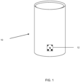
- Figure 1 shows an example of a packaging 10 in the form of a can with a security marking 12.
- the security marking 12 serves to identify the packaging 10 as packaging for which a deposit must be paid upon purchase by a consumer, which the consumer receives back upon return of the packaging.
- the security marking is designed in such a way that it is not readily possible to apply the security marking to packaging for which no deposit has been paid. Since the deposit value is greater than the packaging value, the party taking back the packaging and paying out the deposit would suffer damage in the case of packaging with a counterfeit security marking.
- Figure 2 shows the essential features of the security marking 12, namely a comparatively highly reflective contrast field 14 enclosing a security field 16 and a signal field 18.
- the contrast field 14 is highly reflective over a broad wavelength range, particularly in the visible wavelength range of light and in the transition to the infrared wavelength range.
- the security field 16 has the property that it is weakly reflective in a first, preferably visible wavelength range of light, i.e. strongly absorbent and therefore appears dark.
- the security field 16 is, however, highly reflective, for example just as highly reflective as the contrast field 14.
- the security field 16 obtains this property of different reflectivity at different wavelengths in that the ink with which the security field 16 is printed has a lower absorption in the second wavelength range than in the first wavelength range.
- the security field 16 when viewing the packaging 10 in the first wavelength range, e.g. in normal daylight, the security field 16 is clearly visible as a dark field against a light background, whereas the security field 16 is less visible when viewed in the second wavelength range, e.g. with the aid of a corresponding camera, since the security field 16 has a higher reflectivity in the second wavelength range, which may be similar to that of the contrast field 14.
- the reflectivity of the respective field for a particular wavelength - and thus the intensity with which light is reflected in a particular wavelength range - depends on the The color with which the respective field is printed on a respective background.
- the color with which the contrast field 14 is printed is a broadband reflective color
- the color with which the dark fields 20 and 22 are printed is a broadband absorbent color.
- the contrast field 14 can also be formed by the background itself if the background itself is broadband reflective, so that the contrast field 14 does not necessarily have to be printed.
- the ink used to print the security field 16 has a higher absorption in the first wavelength range than in the second wavelength range. Accordingly, the ink used to print the security field 16 has a higher reflectivity or a higher transparency, or both, in the second wavelength range than in the first wavelength range. If the ink used to print the security field 16 has a higher reflectivity in the second wavelength range than in the first wavelength range, the intensity of the reflected light in the second wavelength range is always greater than the intensity of the reflected light in the first wavelength range.
- the intensity of the reflected light in the second wavelength range is greater than the intensity of the reflected light in the first wavelength range if the background beneath the ink used to print the security field 16 has a sufficiently high reflectivity in this second wavelength range. If the ink with which the security field 16 is printed already has a high reflectivity in the second wavelength range, the reflectivity of the background beneath the ink with which the security field 16 is printed is less important or not important at all.
- the background beneath the ink used to print the security field 16 has a reflectivity that differs from the reflectivity of the contrast field 14.
- the security field 16 can be printed with two colors, namely first with a first color with reflective properties that differ from those of the contrast field 14, and then with a second color, such that the second color covers the first color.
- the second color used to print the security field 16 is then the color that, as previously described, has a higher reflectivity and/or transparency in the second wavelength range than in the first wavelength range.
- the security field 16 has an asymmetrical shape so that its orientation in relation to the rest of the security marking can be clearly identified.
- Signal field 18 serves to signal a device for reading the security marking whether and, if so, which stored parameters should be considered when checking the security marking.
- Parameters can be, for example, stored correction factors.
- the security marking 12' preferably has further fields, namely dark fields in the form of corner markings 20 and in the form of orientation markings 22.
- the dark fields 20 and 22 have the property of being strongly absorbing, i.e. weakly reflecting, in both the first wavelength range and the second wavelength range and thus appearing dark.
- one or more of the dark fields - similar to the security field - can be printed with two colors, namely first with a first color with reflection properties that differ from those of the contrast field 14, and then with a second color, so that the second color covers the first color, wherein the second color has a higher reflectivity and/or transparency in the second wavelength range than in the first wavelength range.
- the security against forgery can be increased even further.
- at least one dark field is broadband absorbent and in both appears dark in both the first wavelength range and the second wavelength range.
- the corner markings 20 are in the shape of right-angled, isosceles triangles. This shape is particularly suitable because such shapes are practically non-existent in other packaging printing.
- the legs of the respective isosceles triangles 20 run parallel to the edges of the security marking 12'. The hypotenuses of the corner markings 20 are thus facing inward with respect to the security marking 12'.
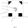
- the orientation markings 22 act, on the one hand, as corner markings for locating two further corners of the overall square safety marking 12'. Furthermore, they enclose the signal field 18 between them, so that it is easy to locate even if it has the same color as the background 14, as is exemplified in Figure 3 is shown.
- Both the corner markings 20 and the orientation markings 22 can also have shapes other than those shown in the exemplary embodiment and can, for example, be composed of several partial areas, so that information can be encoded with the corner markings 20 and/or orientation markings 22, similar to how this is done with the aid of the signal field 18.
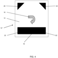
- Figure 4 basically shows the same safety marking 12" as Figure 3 .
- the only difference between the 12" safety marking from Figure 4 opposite the safety marking 12' Figure 3 is that the safety field 18 at the 12" safety marking consists of Figure 4 weakly reflective, i.e. dark, and thus has the same colour as the orientation markings 22 and the corner markings 20, while the safety field 18' of the safety marking 12' consists of Figure 3 is highly reflective and therefore has the same color as the contrast field 14.
- Figure 5 shows a variant of a 12′′′ security marking with a signal field 18", which is divided into a total of 8 sub-signal fields, which are either highly or weakly reflective.
- the eight sub-fields can thus represent an 8-bit (1 byte) code.
- the signal field 18" represents the byte 10100110 or 01011001, depending on whether a strong or a weak reflectivity is assigned to the bit value 1.
- 256-value information such as a multitude of different correction factors for, for example, different packaging.
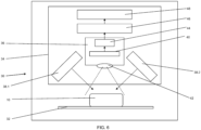
- the reading device 30, which can be part of a reverse vending machine for beverage packaging, for example, has a transport device 32 with which a packaging 10' can be positioned in front of a reading unit 34 such that it is in the field of view of the image capture unit 36 of the reading unit 34.
- the field of view is in Figure 5 indicated by dashed diagonal lines.
- a lighting module which has two lighting units 38.1 and 38.2.
- the direction of illumination and thus the angle at which the illumination falls on a package 10 to be read are indicated by dotted arrows.
- the illumination angle should be between 20° and 45° relative to the surface normal of the package 10.
- the lighting units 38.1 and 38.2 of the lighting module are arranged and aligned accordingly.
- the lighting units 38.1 and 38.2 have a plurality of light-emitting diodes (LEDs) as light sources.
- the lighting unit 38.1 is designed to illuminate the packaging 10 with light intensity of the reflected light in the second wavelength range, while the lighting unit 38.2 illuminates the packaging unit 10 with light intensity of the reflected light in the first wavelength range.
- the lighting unit 38.2 has two types of light-emitting diodes, namely a first type of light-emitting diode that emits blue, visible light and a second type of light-emitting diode that emits red, visible light.
- the visible light emitted by the lighting unit 38.2 is thus composed of two wavelength ranges, each with a central wavelength in the blue range of the visible spectrum and a central wavelength in the red range of the visible spectrum.
- the half-value bandwidth of the two The wavelength ranges emitted by the visible light illumination module 38.2 are each less than 50 nm.
- the lighting module and its lighting units 38.1 and 38.2 With the help of the lighting module and its lighting units 38.1 and 38.2, specific lighting scenarios can be set.
- the lighting units 38.1 and 38.2 are operated alternately, so that the packaging 10 is illuminated either only with light in the second wavelength range from the lighting unit 38.1 or with light in the first wavelength range from the lighting unit 38.2.
- the light reflected from the surface of the packaging 10 is recorded by the image capture module 36.
- the image capture module 36 has an area sensor 40 and an optical system 42, which projects an image of the surface of the packaging 10 sharply onto a surface of the area sensor 40.
- the surface of the area sensor 40 is formed by a plurality of light-sensitive sensor elements. These are preferably arranged in a matrix.
- the sensor elements of the area sensor 40 and the optical system 42 are designed such that one square millimeter of the surface of the packaging 10 is projected onto a partial surface of the area sensor 40 such that the partial surface contains at least four complete sensor elements.
- the imaging scale with which the optical system 42 projects an image of the surface of the packaging 10 onto the surface of the area sensor 40 depends on the size of the sensor elements on the surface of the area sensor 40 and the distance between the sensor elements. It goes without saying that the optics 42 are designed such that they sharply image the surface of the packaging 10 on the area sensor 40 in the region of a depth of field required by varying packaging diameters.
- the sensor elements of the area sensor 40 are broadband light-sensitive, meaning at least in the partial wavelength ranges of the light emitted simultaneously or alternately by the illumination units 38.1 and 38.2.
- the output value provided by each individual sensor element of the area sensor 40 also referred to here as the gray value—corresponds to the total intensity of all light in the various wavelength ranges detected by the respective sensor element.
- the output value provided by a respective sensor element of the area sensor 40 is greater the greater the total intensity of the light impinging on the respective sensor element.
- the total intensity of the light impinging on the respective sensor element is composed of the partial intensities of the light in the various wavelength ranges that make up the light impinging on a respective sensor element.
- This total intensity is the intensity of the light detected by the sensor element in the second wavelength range when the packaging is illuminated exclusively by the illumination unit 38.1 with light in the second wavelength range.
- the output value of a respective sensor element corresponds to the respective intensity in the first wavelength range of the light when the packaging surface is illuminated exclusively by the illumination unit 38.2 with light in the first wavelength range.
- the light intensity detected by a respective sensor element - and thus the output gray value - depends on the sum of the intensity with which a respective surface element assigned to the sensor element via the image reflects light in the first wavelength range and in the second wavelength range.
- sensor elements that, for example, detect part of the contrast field 14 of the security marking 12 always detect a high brightness value and thus deliver a high output value—and thus a high gray value w i .
- sensor elements that detect part of an orientation marking 22 or a corner marking 20 will always detect a low brightness value and thus also deliver a low output value and gray value s i , regardless of whether the illumination is with light in the first wavelength range or with light in the second wavelength range.
- the gray value d i delivered by a sensor element onto which part of the security field 16 is imaged depends, however, on the type of illumination.
- the intensity reflected by the security field 16 is low, so that a part of the security field 16 detecting sensor element only delivers a low gray value d 1 .
- the intensity of the light reflected by the security field is significantly higher - depending on the background - and can, for example, correspond to the intensity reflected by the contrast field 14. Accordingly, a sensor element on which part of the security field is imaged delivers a high gray value d 2 when the packaging 10 is illuminated with light in the second wavelength range. If, on the other hand, the packaging 10 is illuminated simultaneously with light in the first wavelength range and in the second wavelength range, the gray value delivered by a sensor element detecting the security field is a medium gray value.
- the gray values supplied by the area sensor 40 are preprocessed in a preprocessing unit 44.
- the processed gray values (output values of the sensor elements of the area sensor 40) are fed to an evaluation unit 46, in which, on the one hand, the various areas of the security marking are detected using pattern recognition methods known per se.
- This image capture of the image of the security marking also serves to determine the location of the signal field 18 in order to read its intensity.
- the evaluation unit 46 activates a different reference threshold for evaluating the intensity of the light reflected by the security field 16 in the second wavelength range.
- the intensity values provided by the various fields of the security marking are compared with the respective reference thresholds to evaluate the respective security marking.
- This evaluation is carried out by an evaluation unit, which is part of the evaluation unit 46 and is therefore Fig. 5 not shown in detail.
- the evaluation of the intensity values represented by corresponding gray values d 2 , which are to be assigned to the safety field 16 when illuminated with light in the second wavelength range, is carried out with reference to the gray values d 1 - and thus the intensity values - which are to be assigned to the safety field 16 when illuminated with light in the first wavelength range Depending on how much the intensity of the reflected light in the second wavelength range deviates from the intensity of the reflected light in the first wavelength range, a package is accepted and the deposit is paid out or not.
- the test by the evaluation unit 46 is carried out according to the following procedure: Firstly, the intensities of the light reflected by the security field in two different wavelength ranges are recorded in the form of grey values d 1 , d 2 . In addition, the intensities of the light reflected by the contrast field in the first wavelength range are recorded in the form of a grey value w 1 , if necessary, averaged. A difference value is derived from the two grey values d 1 and d 2 , which represent the different intensities of the light reflected by the security field in the two different wavelength ranges. A correction value is derived from the grey value w 1 , which represents the intensity of the light reflected by the contrast field when illuminated with light in the first wavelength range, and used to correct the difference value determined from the intensities of the light reflected by the security field.
- the difference value is calculated so that it also depends on the intensities of the light reflected by the dark field.
- a difference can first be calculated for each wavelength range between the intensities of the light reflected by the security field and the dark field. This can be done by calculating a first gray value s i for each wavelength range, which represents the intensity of the light reflected by the dark field in the respective wavelength range. This first gray value s i can be subtracted from a second gray value d i , which represents the intensity of the light reflected by the security field in the same wavelength range. In this way, a contrast value can be calculated for each of the two wavelength ranges. The difference between the two contrast values thus calculated can then be calculated.
- the difference between a gray value d i of the security field and a gray value s i of the dark field for a respective wavelength range i can be understood as a contrast value (d i - s i ), which represents the contrast of the security field to the dark field.
- the contrast value is greater the more the security field reflects light in the first or second wavelength range, ie the greater the brightness difference between the dark field and the security field when illuminated in the respective wavelength range. Since the security field in the first wavelength range If the reflectivity of the security field is less pronounced in the second wavelength range than in the second wavelength range, the contrast value for the second wavelength range is greater than for the first wavelength range.
- the difference value is calculated as the difference ((d 1 - s 1 ) - (d 2 - s 2 )) between two contrast values, the difference value is a measure of how much greater the reflectivity of the security field is in the second wavelength range compared to the reflectivity in the first wavelength range.
- each contrast value is normalized using a maximum contrast value, which represents the difference between a gray value w i of the contrast field and a gray value s i of the dark field for a respective wavelength range. Normalization can be achieved by dividing the respective contrast value by the corresponding maximum contrast value, thus forming a normalized contrast value for each of the two wavelength ranges.
- the difference value is preferably the difference between the normalized contrast values.
- the product of the correction factor k and the gray value w 1 of the contrast field for light in the first wavelength range forms the aforementioned correction value.
- the gray value w 1 of the contrast field in the first wavelength range can also be used as a correction value.
- the difference between the contrast values ( d 2 - s 2 ) - ( d 1 - s 1 ) is thus normalized with a value - namely the gray value w 1 of the contrast field - which depends on the distance of the safety marking to the respective light source.
- the correction factor k is preferably a constant that has been determined in advance for a respective readout unit or a respective readout unit type and is stored in the respective readout unit.
- the evaluation unit 46 is also connected to a control unit 48, which serves, for example, to control the lighting units 38.1 and 38.2 and which also controls the transport device 32, for example, to rotate the packaging 10 by means of the transport device 32 such that the security marking on the surface of the packaging 10 is within the field of view of the reading unit 34.
- Image recognition by the evaluation unit 46 also serves this purpose.
- the control unit also controls the deposit refund and the return of packaging.
Landscapes
- Physics & Mathematics (AREA)
- General Physics & Mathematics (AREA)
- Spectroscopy & Molecular Physics (AREA)
- Health & Medical Sciences (AREA)
- General Health & Medical Sciences (AREA)
- Toxicology (AREA)
- Engineering & Computer Science (AREA)
- Computer Vision & Pattern Recognition (AREA)
- Inspection Of Paper Currency And Valuable Securities (AREA)
- Credit Cards Or The Like (AREA)
- Investigating Materials By The Use Of Optical Means Adapted For Particular Applications (AREA)
Claims (12)
- Procédé de contrôle d'un marquage (12) de sécurité, qui a au moins un champ (14) de contraste ayant une réflectivité relativement grande dans un premier et un deuxième domaine de longueurs d'onde et un champ (16) de sécurité, qui a des propriétés de réflexion dans le premier domaine de longueurs d'onde autre que dans le deuxième domaine de longueurs d'onde, dans lequel le procédé de contrôle comprend les stades suivants :- détection des intensités de la lumière réfléchie par le champ (16) de sécurité dans les deux domaines de longueurs d'onde différents, les intensités de la lumière réfléchie par le champ de sécurité dans deux domaines de longueurs d'onde différents étant détectées sous la forme de valeurs de gris,- formation d'une valeur de différence sur la base des deux intensités différentes de la lumière réfléchie par le champ (16) de sécurité dans les deux domaines de longueurs d'onde différents, dans lequel la valeur de différence représente la mesure, suivant laquelle les valeurs de gris dans la partie de la représentation du champ de sécurité, lors de l'éclairage par de la lumière dans le deuxième domaine de longueurs d'onde, s'écartent des valeurs de gris, lors de l'éclairage par de la lumière dans le premier domaine de longueurs d'onde,- détection de l'intensité de la lumière réfléchie par le champ (14) de contraste dans le premier domaine de longueurs d'onde,- formation d'une valeur de correction sur la base de l'intensité de la lumière réfléchie par le champ (14) de contraste, lors de l'éclairage par de la lumière dans le premier domaine de longueurs d'onde et- correction de la valeur de différence à l'aide de la valeur de la correction- évaluation du marquage (12) de sécurité sur la base des valeurs de gris détectées- dans lequel, dans le cas où la valeur de différence corrigée correspond à une mesure donnée à l'avance, l'évaluation du marquage de sécurité s'effectue comme étant en règle et- sinon une évaluation s'effectue comme n'étant pas en règle.
- Procédé de contrôle suivant la revendication 1 d'un marquage (12) de sécurité, qui a en outre au moins un champ (20, 22) noir ayant une réflectivité relativement petite dans un premier et un deuxième domaine de longueurs d'onde, caractérisé en ce que l'on forme la valeur de différence comme différence de deux valeurs de contraste, dont une première valeur de contraste reflète une différence des intensités de la lumière réfléchie par le champ (16) de sécurité et le champ (20, 22) noir dans le premier domaine de longueurs d'onde, et une deuxième valeur de contraste une différence des intensités de la lumière réfléchie par le champ (16) de sécurité et le champ (20, 22) noir dans le deuxième domaine de longueurs d'onde.
- Procédé de contrôle suivant la revendication 2, caractérisé en ce que l'on norme les valeurs de contraste en tenant compte de la valeur de correction.
- Procédé de contrôle suivant au moins l'une des revendications 1 à 3, caractérisé en ce que l'on effectue le contrôle du marquage (12) de sécurité et en particulier le contrôle du champ (16) de sécurité dans plus de deux domaines de longueurs d'onde différents de la lumière.
- Marquage (12) de sécurité, qui a au moins un champ (14) de contraste ayant une réflectivité relativement grande dans un premier et un deuxième domaine de longueurs d'onde et un champ (16) de sécurité, qui a dans le premier domaine de longueurs d'onde des propriétés de réflexion autres que dans le deuxième domaine de longueurs d'onde, caractérisé en ce que le champ (16) de sécurité est imprimé en deux couleurs, à savoir d'abord une première couleur ayant des propriétés de réflexion, qui s'écartent de celles du champ (14) de contraste, et ensuite en une deuxième couleur, de sorte que la deuxième couleur recouvre la première couleur, dans lequel la deuxième couleur a, dans le deuxième domaine de longueurs d'onde, une réflectivité plus grande et/ou une transparence plus grande que dans le premier domaine de longueurs d'onde.
- Marquage (12) de sécurité suivant la revendication 5, qui a en outre au moins un champ (20, 22) noir ayant une réflectivité relativement petite dans un premier et un deuxième domaine de longueurs d'onde, dans lequel le champ (20 ; 22) noir est imprimé en deux couleurs, à savoir d'abord en une première couleur ayant des propriétés de réflexion, qui s'écartent de celles du champ (14) de contraste, et ensuite en une deuxième couleur de sorte que la deuxième couleur recouvre la première couleur, dans lequel la deuxième couleur a, dans le deuxième domaine de longueurs d'onde, une réflectivité plus grande et/ou une transparence plus grande que dans le premier domaine de longueurs d'onde.
- Unité (34) de lecture d'un marquage (12) de sécurité, qui a au moins un champ (14) de contraste ayant une réflectivité relativement grande dans un premier et un deuxième domaine de longueurs d'onde et un champ (16) de sécurité, qui a des propriétés de réflexion dans le premier domaine de longueurs d'onde autres que dans le deuxième domaine de longueurs d'onde, caractérisée en ce que l'unité (34) de lecture est constituée,- pour détecter sous la forme de valeurs de gris la lumière dans au moins deux domaines de longueurs d'onde différents réfléchie par le champ (16) de sécurité du marquage (12) de sécurité, dans lequel un domaine de longueurs d'onde est un domaine de longueurs d'onde, dans lequel le champ (16) de sécurité a une réflectivité grande, tandis que l'autre domaine de longueurs d'onde est un domaine de longueurs d'onde, dans lequel le champ (16) de sécurité a une réflectivité petite (grande absorption),- pour former une valeur de différence sur la base des deux intensités différentes de la lumière réfléchie par le champ (16) de sécurité dans les deux domaines de longueurs d'onde différents, dans lequel la valeur de différence représente la mesure suivant laquelle les valeurs de gris dans la partie de la reproduction du champ de sécurité s'écartent, lors de l'éclairage par de la lumière dans les deux domaines de longueurs d'onde, des valeurs de gris, lors de l'éclairage par de la lumière dans le premier domaine de longueurs d'onde,- pour détecter une intensité de la lumière réfléchie par le champ (14) de contraste dans le premier domaine de longueurs d'onde,- pour former une valeur de correction sur la base de l'intensité de la lumière réfléchie par le champ (14) de contraste, lors de l'éclairage par de la lumière dans le premier domaine de longueurs d'onde,- pour corriger la valeur de différence à l'aide de la valeur de correction,- pour évaluer le marquage (12) de sécurité sur la base des valeurs de gris détectées, de manière à ce que, dans le cas où la valeur de différence corrigée correspond à une mesure donnée à l'avance, l'évaluation du marquage de sécurité s'effectue comme étant en règle et sinon une évaluation s'effectue comme n'étant pas en règle.
- Unité (34) de lecture suivant la revendication 7, caractérisée en ce que l'unité de lecture comporte un module (36) de détection d'image ayant un capteur (40) de surface, ayant des éléments capteurs sensibles à la lumière, disposés de préférence sous la forme d'une matrice, pour la détection d'une image en deux dimensions reproduite sur le capteur, qui sont sensibles à la lumière à la fois dans le premier domaine de longueurs d'onde de la lumière et dans le deuxième domaine de longueurs d'onde de la lumière.
- Unité (34) de lecture suivant la revendication 8, caractérisée en ce que l'unité (34) de lecture comporte un module (38.1, 38.2) d'éclairage, qui est constitué et disposé pour éclairer une partie visible du module (36) de détection d'image en même temps ou en alternance par de la lumière dans le premier domaine de longueurs d'onde et dans le deuxième domaine de longueurs d'onde.
- Unité (34) de lecture suivant la revendication 9, caractérisée en ce que le module (38.1, 38.2) d'éclairage rayonne, lorsque l'unité (34) de lecture est en fonctionnement, de la lumière dans le domaine des longueurs d'onde visibles avec deux longueurs d'onde principales, dont l'une correspond à de la lumière rouge et dont l'autre correspond à de la lumière bleue.
- Unité (34) de lecture suivant la revendication 9 ou 10, caractérisée en ce que le module (38.1, 38.2) d'éclairage, comporte des diodes électroluminescentes comme source lumineuse.
- Unité (34) de lecture suivant la revendication 11, caractérisée en ce que le module (38.1, 38.2) d'éclairage, comporte des diodes électroluminescentes différentes, dont un premier nombre de diodes électroluminescentes émet, lorsque l'unité (34) de lecture est en fonctionnement, de la lumière dans un deuxième domaine de longueurs d'onde, dont la longueur d'onde est adaptée à la couleur du champ (16) de sécurité, de manière à ce que la longueur d'onde émise soit au maximum de 100 nm au-dessus d'une longueur d'onde, à laquelle l'absorption de la couleur représente moins de 40 % de l'absorption de la couleur dans le premier domaine de longueurs d'onde.
Priority Applications (1)
| Application Number | Priority Date | Filing Date | Title |
|---|---|---|---|
| HRP20250663TT HRP20250663T1 (hr) | 2018-05-15 | 2019-05-14 | Postupak ispitivanja i uređaj za očitavanje zaštitne oznake |
Applications Claiming Priority (1)
| Application Number | Priority Date | Filing Date | Title |
|---|---|---|---|
| DE102018111680 | 2018-05-15 |
Publications (3)
| Publication Number | Publication Date |
|---|---|
| EP3570256A1 EP3570256A1 (fr) | 2019-11-20 |
| EP3570256B1 true EP3570256B1 (fr) | 2025-04-30 |
| EP3570256C0 EP3570256C0 (fr) | 2025-04-30 |
Family
ID=66554192
Family Applications (1)
| Application Number | Title | Priority Date | Filing Date |
|---|---|---|---|
| EP19174501.7A Active EP3570256B1 (fr) | 2018-05-15 | 2019-05-14 | Procédé de vérification et dispositif de lecture pour un marquage de sécurité |
Country Status (5)
| Country | Link |
|---|---|
| EP (1) | EP3570256B1 (fr) |
| ES (1) | ES3034494T3 (fr) |
| HR (1) | HRP20250663T1 (fr) |
| HU (1) | HUE071674T2 (fr) |
| PL (1) | PL3570256T3 (fr) |
Families Citing this family (2)
| Publication number | Priority date | Publication date | Assignee | Title |
|---|---|---|---|---|
| EP3825140B1 (fr) * | 2019-11-25 | 2023-12-27 | Envipco Holding N.V. | Marque de sécurité, procédure de détection d'un marque de sécurité et système de détection d'un marque de sécurité |
| WO2024155729A1 (fr) | 2023-01-18 | 2024-07-25 | Sun Chemical Corporation | Système de marquage et de vérification de sécurité |
Citations (1)
| Publication number | Priority date | Publication date | Assignee | Title |
|---|---|---|---|---|
| EP1821096B1 (fr) * | 2006-02-20 | 2012-04-11 | DPG Deutsche Pfandsystem GmbH | Dispositif de sélection pour un signet d'un emballage |
Family Cites Families (4)
| Publication number | Priority date | Publication date | Assignee | Title |
|---|---|---|---|---|
| DE4319555A1 (de) | 1993-06-13 | 1994-12-15 | Tetra Pak Aps Gmbh | Markierung in Form von Farbzeichen |
| DE20221928U1 (de) | 2002-10-10 | 2009-05-20 | Envipco Holding N.V. | Sicherheitscode und Vorrichtung zum Sortieren und/oder Sammeln von Materialien, wie Mehrweg- und/oder Einweggetränkeverpackungen |
| DE102006011143B4 (de) | 2005-11-04 | 2016-04-28 | Envipco Holding N.V. | Verfahren zur Detektion einer Sicherheitsmarkierung und Sicherheitsmarkierung zur Durchführung des Verfahrens |
| DE102013103527A1 (de) * | 2013-04-09 | 2014-10-09 | Bundesdruckerei Gmbh | Bildaufnahmesystem zur Bildaufnahme von Merkmalen eines Identifikationsdokumentes |
-
2019
- 2019-05-14 EP EP19174501.7A patent/EP3570256B1/fr active Active
- 2019-05-14 PL PL19174501.7T patent/PL3570256T3/pl unknown
- 2019-05-14 HU HUE19174501A patent/HUE071674T2/hu unknown
- 2019-05-14 HR HRP20250663TT patent/HRP20250663T1/hr unknown
- 2019-05-14 ES ES19174501T patent/ES3034494T3/es active Active
Patent Citations (1)
| Publication number | Priority date | Publication date | Assignee | Title |
|---|---|---|---|---|
| EP1821096B1 (fr) * | 2006-02-20 | 2012-04-11 | DPG Deutsche Pfandsystem GmbH | Dispositif de sélection pour un signet d'un emballage |
Non-Patent Citations (1)
| Title |
|---|
| ANONYMOUS: "Punktoperator (Bildverarbeitung) - Wikipedia", 2 February 2018 (2018-02-02), XP055971373, Retrieved from the Internet <URL:https://de.wikipedia.org/w/index.php?title=Punktoperator_(Bildverarbeitung)&oldid=173592796> [retrieved on 20221014] * |
Also Published As
| Publication number | Publication date |
|---|---|
| EP3570256A1 (fr) | 2019-11-20 |
| ES3034494T3 (en) | 2025-08-19 |
| HRP20250663T1 (hr) | 2025-10-10 |
| PL3570256T3 (pl) | 2025-08-11 |
| HUE071674T2 (hu) | 2025-09-28 |
| EP3570256C0 (fr) | 2025-04-30 |
Similar Documents
| Publication | Publication Date | Title |
|---|---|---|
| DE60112890T3 (de) | Verfahren zur überwachung von dokumenten | |
| EP2290355B1 (fr) | Dispositif et procédé destinés à l'inspection de récipients étiquetés | |
| DE2858266C2 (de) | Wertzeichen wie Kredit- oder Ausweiskarte | |
| EP1196885B1 (fr) | Dispositif de lecture pour bande d'information comportant une information codee optiquement | |
| EP3746992A1 (fr) | Procédé pour le contrôle de l'authenticité et/ou de l'intégrité d'un document de sécurité comprenant une caractéristique de sécurité imprimée, caractéristique de sécurité et dispositif pour la vérification | |
| EP4014211B1 (fr) | Objet qui comprend des particules de marqueurs de fluorescence et son procédé d'identification | |
| EP1821096B1 (fr) | Dispositif de sélection pour un signet d'un emballage | |
| EP3570256B1 (fr) | Procédé de vérification et dispositif de lecture pour un marquage de sécurité | |
| DE102019005656A1 (de) | Verfahren und Vorrichtung zum Prüfen von Wertdokumenten | |
| DE102016000011A1 (de) | Vollständigkeitsprüfung eines Wertdokuments | |
| EP3841524B1 (fr) | Procédé de contrôle et dispositif de contrôle destinés au contrôle de marquages de sécurité | |
| DE10005835A1 (de) | Automatische Authentifikation von mit Sicherheitsmerkmalen geschützten Dokumenten | |
| DE102006011143A1 (de) | Sicherheitsmarkierungssystem | |
| EP3443542B1 (fr) | Dispositif et procédé de vérification de documents de valeur, en particulier des billets de banque, et système de traitement de documents de valeur | |
| DE102005016824A1 (de) | Vorrichtung und Verfahren zur Prüfung von Wertdokumenten | |
| DE102016100437A1 (de) | Vorrichtung zur Druckbildkontrolle | |
| DE69722230T2 (de) | Verfahren und einrichtung zur feststellung von pfandwertanzeigen | |
| EP3825140B1 (fr) | Marque de sécurité, procédure de détection d'un marque de sécurité et système de détection d'un marque de sécurité | |
| DE102020210935B3 (de) | Auslesevorrichtung zum Auslesen holographisch abgelegter Informationen, Verfahren zum Auslesen holographisch abgelegter Informationen | |
| AT514660B1 (de) | Verfahren zur Prüfung eines Gegenstands auf Echtheit | |
| WO2017194190A1 (fr) | Dispositif et procédé de vérification en temps réel d'un élément de sécurité | |
| EP4555496A1 (fr) | Capteur et procédé de vérification de documents de valeur comprenant au moins un élément de sécurité réfléchissant | |
| DE102018101255B4 (de) | Vorrichtung zur Laserindividualisierung sowie Verfahren zur Justierung derselben | |
| DE202005020646U1 (de) | Sicherheitsmarkierungssystem | |
| EP3503048B1 (fr) | Procédé et dispositif destinés à la verification d'un document de valeur |
Legal Events
| Date | Code | Title | Description |
|---|---|---|---|
| REG | Reference to a national code |
Ref country code: HR Ref legal event code: TUEP Ref document number: P20250663T Country of ref document: HR |
|
| PUAI | Public reference made under article 153(3) epc to a published international application that has entered the european phase |
Free format text: ORIGINAL CODE: 0009012 |
|
| STAA | Information on the status of an ep patent application or granted ep patent |
Free format text: STATUS: THE APPLICATION HAS BEEN PUBLISHED |
|
| AK | Designated contracting states |
Kind code of ref document: A1 Designated state(s): AL AT BE BG CH CY CZ DE DK EE ES FI FR GB GR HR HU IE IS IT LI LT LU LV MC MK MT NL NO PL PT RO RS SE SI SK SM TR |
|
| AX | Request for extension of the european patent |
Extension state: BA ME |
|
| STAA | Information on the status of an ep patent application or granted ep patent |
Free format text: STATUS: REQUEST FOR EXAMINATION WAS MADE |
|
| 17P | Request for examination filed |
Effective date: 20200520 |
|
| RBV | Designated contracting states (corrected) |
Designated state(s): AL AT BE BG CH CY CZ DE DK EE ES FI FR GB GR HR HU IE IS IT LI LT LU LV MC MK MT NL NO PL PT RO RS SE SI SK SM TR |
|
| STAA | Information on the status of an ep patent application or granted ep patent |
Free format text: STATUS: EXAMINATION IS IN PROGRESS |
|
| 17Q | First examination report despatched |
Effective date: 20221020 |
|
| P01 | Opt-out of the competence of the unified patent court (upc) registered |
Effective date: 20230523 |
|
| GRAP | Despatch of communication of intention to grant a patent |
Free format text: ORIGINAL CODE: EPIDOSNIGR1 |
|
| STAA | Information on the status of an ep patent application or granted ep patent |
Free format text: STATUS: GRANT OF PATENT IS INTENDED |
|
| INTG | Intention to grant announced |
Effective date: 20240531 |
|
| GRAJ | Information related to disapproval of communication of intention to grant by the applicant or resumption of examination proceedings by the epo deleted |
Free format text: ORIGINAL CODE: EPIDOSDIGR1 |
|
| STAA | Information on the status of an ep patent application or granted ep patent |
Free format text: STATUS: EXAMINATION IS IN PROGRESS |
|
| INTC | Intention to grant announced (deleted) | ||
| GRAS | Grant fee paid |
Free format text: ORIGINAL CODE: EPIDOSNIGR3 |
|
| STAA | Information on the status of an ep patent application or granted ep patent |
Free format text: STATUS: GRANT OF PATENT IS INTENDED |
|
| GRAP | Despatch of communication of intention to grant a patent |
Free format text: ORIGINAL CODE: EPIDOSNIGR1 |
|
| INTG | Intention to grant announced |
Effective date: 20241120 |
|
| GRAA | (expected) grant |
Free format text: ORIGINAL CODE: 0009210 |
|
| STAA | Information on the status of an ep patent application or granted ep patent |
Free format text: STATUS: THE PATENT HAS BEEN GRANTED |
|
| AK | Designated contracting states |
Kind code of ref document: B1 Designated state(s): AL AT BE BG CH CY CZ DE DK EE ES FI FR GB GR HR HU IE IS IT LI LT LU LV MC MK MT NL NO PL PT RO RS SE SI SK SM TR |
|
| REG | Reference to a national code |
Ref country code: CH Ref legal event code: EP Ref country code: GB Ref legal event code: FG4D Free format text: NOT ENGLISH |
|
| REG | Reference to a national code |
Ref country code: IE Ref legal event code: FG4D Free format text: LANGUAGE OF EP DOCUMENT: GERMAN |
|
| REG | Reference to a national code |
Ref country code: DE Ref legal event code: R096 Ref document number: 502019013273 Country of ref document: DE |
|
| U01 | Request for unitary effect filed |
Effective date: 20250530 |
|
| U07 | Unitary effect registered |
Designated state(s): AT BE BG DE DK EE FI FR IT LT LU LV MT NL PT RO SE SI Effective date: 20250610 |
|
| PGFP | Annual fee paid to national office [announced via postgrant information from national office to epo] |
Ref country code: IS Payment date: 20250630 Year of fee payment: 7 Ref country code: NO Payment date: 20250523 Year of fee payment: 7 |
|
| P04 | Withdrawal of opt-out of the competence of the unified patent court (upc) registered |
Free format text: CASE NUMBER: APP_26682/2025 Effective date: 20250604 |
|
| PGFP | Annual fee paid to national office [announced via postgrant information from national office to epo] |
Ref country code: HR Payment date: 20250603 Year of fee payment: 7 |
|
| U20 | Renewal fee for the european patent with unitary effect paid |
Year of fee payment: 7 Effective date: 20250611 |
|
| PGFP | Annual fee paid to national office [announced via postgrant information from national office to epo] |
Ref country code: HU Payment date: 20250605 Year of fee payment: 7 |
|
| REG | Reference to a national code |
Ref country code: HR Ref legal event code: ODRP Ref document number: P20250663T Country of ref document: HR Payment date: 20250603 Year of fee payment: 7 |
|
| PGFP | Annual fee paid to national office [announced via postgrant information from national office to epo] |
Ref country code: CH Payment date: 20250601 Year of fee payment: 7 |
|
| PGFP | Annual fee paid to national office [announced via postgrant information from national office to epo] |
Ref country code: RO Payment date: 20250515 Year of fee payment: 7 |
|
| PGFP | Annual fee paid to national office [announced via postgrant information from national office to epo] |
Ref country code: SK Payment date: 20250514 Year of fee payment: 7 |
|
| PGFP | Annual fee paid to national office [announced via postgrant information from national office to epo] |
Ref country code: CZ Payment date: 20250514 Year of fee payment: 7 |
|
| PGFP | Annual fee paid to national office [announced via postgrant information from national office to epo] |
Ref country code: IE Payment date: 20250522 Year of fee payment: 7 |
|
| REG | Reference to a national code |
Ref country code: SK Ref legal event code: T3 Ref document number: E 46531 Country of ref document: SK |
|
| REG | Reference to a national code |
Ref country code: ES Ref legal event code: FG2A Ref document number: 3034494 Country of ref document: ES Kind code of ref document: T3 Effective date: 20250819 |
|
| REG | Reference to a national code |
Ref country code: GR Ref legal event code: EP Ref document number: 20250401355 Country of ref document: GR Effective date: 20250808 |
|
| REG | Reference to a national code |
Ref country code: HU Ref legal event code: AG4A Ref document number: E071674 Country of ref document: HU |
|
| PGFP | Annual fee paid to national office [announced via postgrant information from national office to epo] |
Ref country code: ES Payment date: 20250630 Year of fee payment: 7 |
|
| REG | Reference to a national code |
Ref country code: HR Ref legal event code: T1PR Ref document number: P20250663 Country of ref document: HR |
|
| PGFP | Annual fee paid to national office [announced via postgrant information from national office to epo] |
Ref country code: GR Payment date: 20250708 Year of fee payment: 7 |
|
| PGFP | Annual fee paid to national office [announced via postgrant information from national office to epo] |
Ref country code: PL Payment date: 20250627 Year of fee payment: 7 |
|
| PGFP | Annual fee paid to national office [announced via postgrant information from national office to epo] |
Ref country code: GB Payment date: 20250827 Year of fee payment: 7 |
|
| PG25 | Lapsed in a contracting state [announced via postgrant information from national office to epo] |
Ref country code: RS Free format text: LAPSE BECAUSE OF FAILURE TO SUBMIT A TRANSLATION OF THE DESCRIPTION OR TO PAY THE FEE WITHIN THE PRESCRIBED TIME-LIMIT Effective date: 20250731 |
|
| PG25 | Lapsed in a contracting state [announced via postgrant information from national office to epo] |
Ref country code: SM Free format text: LAPSE BECAUSE OF FAILURE TO SUBMIT A TRANSLATION OF THE DESCRIPTION OR TO PAY THE FEE WITHIN THE PRESCRIBED TIME-LIMIT Effective date: 20250430 |
|
| PGFP | Annual fee paid to national office [announced via postgrant information from national office to epo] |
Ref country code: CY Payment date: 20250519 Year of fee payment: 7 |
|
| PG25 | Lapsed in a contracting state [announced via postgrant information from national office to epo] |
Ref country code: MC Free format text: LAPSE BECAUSE OF FAILURE TO SUBMIT A TRANSLATION OF THE DESCRIPTION OR TO PAY THE FEE WITHIN THE PRESCRIBED TIME-LIMIT Effective date: 20250430 |
|
| PLBE | No opposition filed within time limit |
Free format text: ORIGINAL CODE: 0009261 |
|
| STAA | Information on the status of an ep patent application or granted ep patent |
Free format text: STATUS: NO OPPOSITION FILED WITHIN TIME LIMIT |
|
| REG | Reference to a national code |
Ref country code: CH Ref legal event code: L10 Free format text: ST27 STATUS EVENT CODE: U-0-0-L10-L00 (AS PROVIDED BY THE NATIONAL OFFICE) Effective date: 20260311 |
|
| 26N | No opposition filed |
Effective date: 20260202 |