EP3570345A1 - Sekundärbatterie und obere abdeckungsanordnung davon - Google Patents
Sekundärbatterie und obere abdeckungsanordnung davon Download PDFInfo
- Publication number
- EP3570345A1 EP3570345A1 EP19173533.1A EP19173533A EP3570345A1 EP 3570345 A1 EP3570345 A1 EP 3570345A1 EP 19173533 A EP19173533 A EP 19173533A EP 3570345 A1 EP3570345 A1 EP 3570345A1
- Authority
- EP
- European Patent Office
- Prior art keywords
- top cover
- valve
- gas exhaust
- secondary battery
- cover assembly
- Prior art date
- Legal status (The legal status is an assumption and is not a legal conclusion. Google has not performed a legal analysis and makes no representation as to the accuracy of the status listed.)
- Granted
Links
Images

Classifications
-
- H—ELECTRICITY
- H01—ELECTRIC ELEMENTS
- H01M—PROCESSES OR MEANS, e.g. BATTERIES, FOR THE DIRECT CONVERSION OF CHEMICAL ENERGY INTO ELECTRICAL ENERGY
- H01M50/00—Constructional details or processes of manufacture of the non-active parts of electrochemical cells other than fuel cells, e.g. hybrid cells
- H01M50/30—Arrangements for facilitating escape of gases
-
- H—ELECTRICITY
- H01—ELECTRIC ELEMENTS
- H01M—PROCESSES OR MEANS, e.g. BATTERIES, FOR THE DIRECT CONVERSION OF CHEMICAL ENERGY INTO ELECTRICAL ENERGY
- H01M10/00—Secondary cells; Manufacture thereof
- H01M10/05—Accumulators with non-aqueous electrolyte
- H01M10/052—Li-accumulators
- H01M10/0525—Rocking-chair batteries, i.e. batteries with lithium insertion or intercalation in both electrodes; Lithium-ion batteries
-
- H—ELECTRICITY
- H01—ELECTRIC ELEMENTS
- H01M—PROCESSES OR MEANS, e.g. BATTERIES, FOR THE DIRECT CONVERSION OF CHEMICAL ENERGY INTO ELECTRICAL ENERGY
- H01M50/00—Constructional details or processes of manufacture of the non-active parts of electrochemical cells other than fuel cells, e.g. hybrid cells
- H01M50/10—Primary casings; Jackets or wrappings
- H01M50/147—Lids or covers
-
- H—ELECTRICITY
- H01—ELECTRIC ELEMENTS
- H01M—PROCESSES OR MEANS, e.g. BATTERIES, FOR THE DIRECT CONVERSION OF CHEMICAL ENERGY INTO ELECTRICAL ENERGY
- H01M50/00—Constructional details or processes of manufacture of the non-active parts of electrochemical cells other than fuel cells, e.g. hybrid cells
- H01M50/10—Primary casings; Jackets or wrappings
- H01M50/183—Sealing members
- H01M50/184—Sealing members characterised by their shape or structure
-
- H—ELECTRICITY
- H01—ELECTRIC ELEMENTS
- H01M—PROCESSES OR MEANS, e.g. BATTERIES, FOR THE DIRECT CONVERSION OF CHEMICAL ENERGY INTO ELECTRICAL ENERGY
- H01M50/00—Constructional details or processes of manufacture of the non-active parts of electrochemical cells other than fuel cells, e.g. hybrid cells
- H01M50/10—Primary casings; Jackets or wrappings
- H01M50/183—Sealing members
- H01M50/186—Sealing members characterised by the disposition of the sealing members
-
- H—ELECTRICITY
- H01—ELECTRIC ELEMENTS
- H01M—PROCESSES OR MEANS, e.g. BATTERIES, FOR THE DIRECT CONVERSION OF CHEMICAL ENERGY INTO ELECTRICAL ENERGY
- H01M50/00—Constructional details or processes of manufacture of the non-active parts of electrochemical cells other than fuel cells, e.g. hybrid cells
- H01M50/30—Arrangements for facilitating escape of gases
- H01M50/308—Detachable arrangements, e.g. detachable vent plugs or plug systems
-
- H—ELECTRICITY
- H01—ELECTRIC ELEMENTS
- H01M—PROCESSES OR MEANS, e.g. BATTERIES, FOR THE DIRECT CONVERSION OF CHEMICAL ENERGY INTO ELECTRICAL ENERGY
- H01M50/00—Constructional details or processes of manufacture of the non-active parts of electrochemical cells other than fuel cells, e.g. hybrid cells
- H01M50/30—Arrangements for facilitating escape of gases
- H01M50/317—Re-sealable arrangements
-
- H—ELECTRICITY
- H01—ELECTRIC ELEMENTS
- H01M—PROCESSES OR MEANS, e.g. BATTERIES, FOR THE DIRECT CONVERSION OF CHEMICAL ENERGY INTO ELECTRICAL ENERGY
- H01M50/00—Constructional details or processes of manufacture of the non-active parts of electrochemical cells other than fuel cells, e.g. hybrid cells
- H01M50/30—Arrangements for facilitating escape of gases
- H01M50/317—Re-sealable arrangements
- H01M50/325—Re-sealable arrangements comprising deformable valve members, e.g. elastic or flexible valve members
-
- H—ELECTRICITY
- H01—ELECTRIC ELEMENTS
- H01M—PROCESSES OR MEANS, e.g. BATTERIES, FOR THE DIRECT CONVERSION OF CHEMICAL ENERGY INTO ELECTRICAL ENERGY
- H01M50/00—Constructional details or processes of manufacture of the non-active parts of electrochemical cells other than fuel cells, e.g. hybrid cells
- H01M50/30—Arrangements for facilitating escape of gases
- H01M50/342—Non-re-sealable arrangements
-
- H—ELECTRICITY
- H01—ELECTRIC ELEMENTS
- H01M—PROCESSES OR MEANS, e.g. BATTERIES, FOR THE DIRECT CONVERSION OF CHEMICAL ENERGY INTO ELECTRICAL ENERGY
- H01M50/00—Constructional details or processes of manufacture of the non-active parts of electrochemical cells other than fuel cells, e.g. hybrid cells
- H01M50/50—Current conducting connections for cells or batteries
- H01M50/572—Means for preventing undesired use or discharge
- H01M50/574—Devices or arrangements for the interruption of current
- H01M50/578—Devices or arrangements for the interruption of current in response to pressure
-
- H—ELECTRICITY
- H01—ELECTRIC ELEMENTS
- H01M—PROCESSES OR MEANS, e.g. BATTERIES, FOR THE DIRECT CONVERSION OF CHEMICAL ENERGY INTO ELECTRICAL ENERGY
- H01M2200/00—Safety devices for primary or secondary batteries
- H01M2200/20—Pressure-sensitive devices
-
- H—ELECTRICITY
- H01—ELECTRIC ELEMENTS
- H01M—PROCESSES OR MEANS, e.g. BATTERIES, FOR THE DIRECT CONVERSION OF CHEMICAL ENERGY INTO ELECTRICAL ENERGY
- H01M50/00—Constructional details or processes of manufacture of the non-active parts of electrochemical cells other than fuel cells, e.g. hybrid cells
- H01M50/10—Primary casings; Jackets or wrappings
- H01M50/172—Arrangements of electric connectors penetrating the casing
- H01M50/174—Arrangements of electric connectors penetrating the casing adapted for the shape of the cells
- H01M50/176—Arrangements of electric connectors penetrating the casing adapted for the shape of the cells for prismatic or rectangular cells
-
- H—ELECTRICITY
- H01—ELECTRIC ELEMENTS
- H01M—PROCESSES OR MEANS, e.g. BATTERIES, FOR THE DIRECT CONVERSION OF CHEMICAL ENERGY INTO ELECTRICAL ENERGY
- H01M50/00—Constructional details or processes of manufacture of the non-active parts of electrochemical cells other than fuel cells, e.g. hybrid cells
- H01M50/50—Current conducting connections for cells or batteries
- H01M50/531—Electrode connections inside a battery casing
-
- H—ELECTRICITY
- H01—ELECTRIC ELEMENTS
- H01M—PROCESSES OR MEANS, e.g. BATTERIES, FOR THE DIRECT CONVERSION OF CHEMICAL ENERGY INTO ELECTRICAL ENERGY
- H01M50/00—Constructional details or processes of manufacture of the non-active parts of electrochemical cells other than fuel cells, e.g. hybrid cells
- H01M50/50—Current conducting connections for cells or batteries
- H01M50/543—Terminals
- H01M50/547—Terminals characterised by the disposition of the terminals on the cells
- H01M50/55—Terminals characterised by the disposition of the terminals on the cells on the same side of the cell
-
- H—ELECTRICITY
- H01—ELECTRIC ELEMENTS
- H01M—PROCESSES OR MEANS, e.g. BATTERIES, FOR THE DIRECT CONVERSION OF CHEMICAL ENERGY INTO ELECTRICAL ENERGY
- H01M50/00—Constructional details or processes of manufacture of the non-active parts of electrochemical cells other than fuel cells, e.g. hybrid cells
- H01M50/50—Current conducting connections for cells or batteries
- H01M50/543—Terminals
- H01M50/552—Terminals characterised by their shape
- H01M50/553—Terminals adapted for prismatic, pouch or rectangular cells
-
- Y—GENERAL TAGGING OF NEW TECHNOLOGICAL DEVELOPMENTS; GENERAL TAGGING OF CROSS-SECTIONAL TECHNOLOGIES SPANNING OVER SEVERAL SECTIONS OF THE IPC; TECHNICAL SUBJECTS COVERED BY FORMER USPC CROSS-REFERENCE ART COLLECTIONS [XRACs] AND DIGESTS
- Y02—TECHNOLOGIES OR APPLICATIONS FOR MITIGATION OR ADAPTATION AGAINST CLIMATE CHANGE
- Y02E—REDUCTION OF GREENHOUSE GAS [GHG] EMISSIONS, RELATED TO ENERGY GENERATION, TRANSMISSION OR DISTRIBUTION
- Y02E60/00—Enabling technologies; Technologies with a potential or indirect contribution to GHG emissions mitigation
- Y02E60/10—Energy storage using batteries
Definitions
- the present disclosure relates to the technical field of energy storage devices, and in particular, to a secondary battery and a top cover assembly thereof.
- a secondary battery such as a lithium-ion battery, produces gas during long-term use. Then, internal pressure of the battery would increase due to the gas production, thereby causing a case of the battery to bulge and deform. As a result, the battery performance decreases.
- the vent is a disposable component. That is, the battery will be destroyed once the battery performs exhausting through the vent. Therefore, the vent has a limited use. Moreover, the current vent cannot solve the problem of gas pressure increasing caused by slow gas production inside the secondary battery.
- the present disclosure provides a secondary battery and a top cover assembly thereof, aiming to meet the above requirements and improve safety of the secondary battery.
- the present disclosure provides a top cover assembly of a secondary battery, the top cover assembly including: a top cover plate; and a valve sleeve.
- the top cover plate includes an accommodation groove and a valve part protruding upward from a bottom wall of the accommodation groove, and the valve part is provided with at least one gas exhaust hole that communicates with an interior of the secondary battery.
- the valve sleeve is accommodated in the accommodation groove and covers the valve part, a gas exhaust passage that communicates with outside is disposed between the valve sleeve and the valve part, and the gas exhaust passage communicates with the at least one gas exhaust hole.
- the valve sleeve is made of a deformable material, the valve sleeve is configured to deform under a force applied by gas exhausted from the at least one gas exhaust hole so as to form the gas exhaust passage between the valve sleeve and the valve part, and the valve sleeve is configured to be in tight coupling with the valve part when the force applied by the gas is smaller than a force under which the valve sleeve begins to deform.
- the top cover assembly further includes a valve cover connected to the top cover plate.
- the valve cover is in position-limit fit with the valve sleeve in a height direction of the secondary battery.
- valve cover seals an opening of the accommodation groove, and an upper surface of the valve cover is coplanar with or below a lower surface of the top cover plate, the valve cover is provided with a venting hole that communicates with outside, and the venting hole communicates with the gas exhaust passage via the accommodation groove.
- an orthographic projection of the venting hole in the height direction of the secondary battery at least partially overlaps with an orthographic projection of the accommodation groove in the height direction of the secondary battery.
- the accommodation groove includes a pillar section and a cone section that communicate with each other, the pillar section is arranged above the cone section in the height direction of the secondary battery, and a part where the pillar section is connected to the cone forms position-fixed fit with the valve cover in the height direction of the secondary battery.
- valve part is provided with a first groove, the first groove opening towards the valve sleeve and communicating with the at least one gas exhaust hole.
- a lower surface of the top cover plate is provided with a second groove, and the at least one gas exhaust hole is located in an area surrounded by an outline of the second groove.
- the at least one gas exhaust hole includes a plurality of gas exhaust holes, each of the plurality of gas exhaust holes communicates with the accommodation groove, and the plurality of gas exhaust holes is arranged at intervals.
- the present disclosure further provides a secondary battery, including: an electrode assembly, a case, and the top cover assembly described above.
- the top cover assembly is connected at an opening of the case to form an encapsulation space, and the electrode assembly is encapsulated in the encapsulation space.
- the electrode assembly includes a first electrode plate, a second electrode plate and a separator disposed between the first electrode plate and the second electrode plate.
- the top cover assembly includes a first electrode terminal electrically connected to the first electrode plate, and a second electrode terminal electrically connected to the second electrode plate.
- the present disclosure provides a top cover assembly of a secondary battery.
- the valve part of the top cover plate is provided with a gas exhaust hole.
- the gas exhaust hole communicates with an interior of the secondary battery, and the valve sleeve covers the valve part.
- a gas exhaust passage that communicates with outside is arranged between the valve part and the valve sleeve.
- an embodiment of the present disclosure provides a secondary battery.
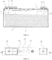
- the secondary battery includes a top cover assembly 1 of the secondary battery (hereinafter referred to as a top cover assembly 1), an electrode assembly 2, and a case 3.
- the top cover assembly 1 seals and is connected to an opening of the case 3 and then an encapsulation space is formed inside the case 3.
- the electrode assembly 2 is encapsulated in the encapsulation space.
- the electrode assembly 2 includes a first electrode plate, a second electrode plate, and a partition plate located between the first electrode plate and the second electrode plate.
- the electrode assembly 2 may be formed by spirally winding the three.
- the electrode assembly 2 may also be formed by stacking multiple first electrode plates, multiple separators and multiple second electrode plates, which are in a form of a plate shape or a sheet shape.
- the first electrode plate and the second electrode plate have different polarities.
- the first electrode plate includes a first coated area coated with an active material and a first tab 21 not coated with an active material.
- the second electrode plate includes a second coated area coated with an active material and a second tab 22 not coated with an active material.
- the top cover assembly 1 includes a first electrode terminal 11 and a second electrode terminal 12. The first tab 21 is connected to the first electrode terminal 11, and the second tab 22 is connected to the second electrode terminal 12, so as to achieve outputting of electric energy of the electrode assembly 2.
- the top cover assembly 1 includes a top cover plate 13.
- the top cover assembly 1 seals and is connected to the case 3 via the top cover plate 13, for example, by welding. Further, the top cover plate 13 serves as a base of the top cover assembly 1 to provide a mounting carrier for other components of the top cover assembly 1, such as the first electrode terminal 11, the second electrode terminal 12, a short circuit member 14 or the like.
- the short circuit member 14 can improve safety of the secondary battery when the secondary battery is overcharged.
- the short circuit member 14 includes a deformable plate 140 and a conductive plate 142.
- the deformable plate 140 is connected to the top cover plate 13.
- the top cover plate 13 is insulated from the first electrode terminal 11 and electrically connected to the second electrode terminal 12.
- the conductive plate 142 is connected to the first electrode terminal 11.
- the top cover assembly 1 further includes a vent 15.
- the vent 15 may open when the internal pressure of the secondary battery reaches its opening pressure, thereby reducing a risk of explosion occurring in the secondary battery.
- the opening pressure of the vent 15 can be larger than the deforming pressure of the deformable plate 140.
- the short circuit member 14 and the vent 15 described above can improve the safety of the secondary battery, but neither of them can solve the problem of gas exhausting when gas is slowly produced inside the secondary battery under a normal operating condition. Therefore, the present disclosure provides a solution which can solve the problem of gas exhausting described above without causing failure of the deformable plate 140 and the vent 15.
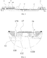
- the top cover plate 13 includes an accommodation groove 130 and a valve part 132 protruding upward from a bottom wall of the accommodation groove 130.
- the valve part 132 occupies only a partial space of the accommodation groove 130.
- the valve part 132 is provided with a gas exhaust hole 1320 that communicates with an interior of the secondary battery.
- the top cover assembly 1 further includes a valve sleeve 16, the valve sleeve 16 is structured as a hollow pillar with a top cover, and the valve part 132 is accommodated in the hollow pillar of the valve sleeve 16. Accordingly, the valve sleeve 16 also covers the gas exhaust hole 1320.
- the valve sleeve 16 is accommodated in the accommodation groove 130, and a gas exhaust passage is arranged between the valve sleeve 16 and the valve part 132 for exhausting gas to outside.
- the gas exhaust passage communicates with the gas exhaust hole 1320.
- the valve sleeve 16 can be made of a deformable material, such as fluoroelastomer or ethylene propylene rubber.
- the gas exhaust passage between the valve part 132 and the valve sleeve 16 can be formed by deformation of the valve sleeve 16.
- the valve sleeve 16 may cover the valve part 132 by means of interference fit.
- the valve sleeve 16 deforms towards a direction away from the valve part 132 under a force.
- the valve sleeve16 is separated from the valve part132, i.e., a gap is formed between the valve sleeve 16 and the valve part 132, and this gap is a gas exhaust passage.
- valve sleeve 16 When an applied force of the gas is smaller than a force under which the valve sleeve 16 deforms, the valve sleeve 16 is restored from deformation. In this case, the valve sleeve 16 and the valve part 132 are restored to interference fit and tight coupling, thereby preventing impurities from entering the interior of the battery. This can achieve one-way gas exhausting in a direction and sealing in an opposite direction.
- a critical pressure under which the valve sleeve 16 deforms can be changed by adjusting an elasticity modulus of the valve sleeve 16.
- the gas exhaust passage may also be formed in a gap reserved between the valve sleeve 16 and the valve part 132.
- the valve sleeve 16 and the valve part 132 can adopt a labyrinth sealing structure, which can also achieve one-way gas exhausting in a direction and sealing in an opposite direction.
- a size of the gas exhaust hole 1320 can be determined according to a gas exhausting rate thereof.
- the gas exhausting rate of the gas exhaust hole 1320 may be set to be smaller than 1/10 of a gas production rate inside the secondary battery. In this way, the internal pressure of the secondary battery resulting from slow gas production then can be reduced without affecting normal deformation of the deformable plate 140 and normal opening of the vent 15. Therefore, the safety of the secondary battery can be improved.
- the gas exhaust hole 1320 can be formed by means of laser processing.
- the top cover assembly 1 may further include a valve cover 17.
- the valve cover 17 is connected to the top cover plate 13 and can be in position-limit fit with the valve sleeve 16 in a height direction of the secondary battery. Under the pressure of the gas exhausted from the gas exhaust hole 1320, the valve sleeve 16 is at risk of escaping from the valve part 132.
- the valve cover 17 can provide position limit for the valve sleeve 16 to prevent the valve sleeve 16 from escaping from the valve part 132, thereby reducing the above risk.
- a structure of the valve cover 17 may be set as required, as long as it satisfies position-limit fit with the valve sleeve 16.
- the valve cover 17 is connected to the top cover plate 13 and seals an opening of the accommodation groove 130.
- the valve cover 17 is also accommodated in the accommodation groove 130 and covers the valve sleeve 16.
- an upper surface of the valve cover 17 may not go beyond an upper surface of the top cover plate 13, so that the valve cover 17 can be prevented from interfering with external objects.
- valve cover 17 covers the valve sleeve 16 and the valve part 132 in a wrap-around structure. In this way, on the one hand, the position-limit fit with the valve sleeve 16 can be effectively achieved, and on the other hand, a risk of impurities entering inside the secondary battery can be reduced, thereby effectively protecting the second battery.
- the valve cover 17 is further provided with a venting hole 170, and the venting hole 170 communicates with the accommodation groove 130.
- the venting hole 170 can communicate with the gas exhaust passage via the accommodation groove 130.
- a partial space of the accommodation groove 130 also serves as a passage for exhausting gas.
- an orthographic projection of the venting hole 170 in the height direction of the second battery at least partially overlaps with an orthographic projection of the accommodation groove in the same direction.
- the accommodation groove 130 is in direct communication with the venting hole 170, thereby shortening a path connecting the two and thus reducing resistance against gas exhausting.
- valve cover 17 is not limited to the structure shown in FIG. 4 and may also have other structures depending on different operation conditions of the secondary battery.
- the accommodation groove 130 includes a pillar section 130a and a cone section 130b that communicating with each other.
- the pillar section 130a is arranged above the cone section 130b in the height direction of the secondary battery. Further, along a direction from an end of the cone section 130b connected to the pillar section 130a to the other end of the cone section 130b, an opening size (for example an inner diameter) of the cone section 130b gradually decreases. In this way, a part where the pillar section 130a is connected to the cone section 130b is used to achieve and position-fixed fit with the valve cover 17, and the valve cover 17 seals and is connected to the top cover plate 13 at this position.
- the accommodation groove 130 being formed as the structure described above can bring an advantage that a small amount of processing error is allowed for the valve cover 17 during processing, in which case the valve cover 17 still seals and is connected to the top cover plate 13.
- the venting hole 170 may have a smaller size, as long as the gas can be smoothly exhausted.
- the venting hole 170 may be shaped as a circle hole with its width being smaller than 1mm. It should be noted that, the venting hole 170 may have other shapes and sizes, and the present disclosure is not limited herein.
- the gas passes the gas exhaust passage (arrow S1 in FIG. 4 ) and a partial space of the accommodation groove 130 (arrow S2 in FIG. 4 ).
- the S1 section is a gap formed between the valve part 132 and the deformed valve sleeve 16
- the S2 section is a gap reserved between an outer wall of the valve sleeve 16 and an inner wall of the valve cover 17 in the accommodation groove 130.
- a first groove 1322 is provided in the valve part 132.
- the first groove 1322 opens towards the valve sleeve 16 and communicates with the gas exhaust hole 1320.
- the gas exhausted from the gas exhaust hole 1320 may gradually gather inside the first groove 1322, and the arrangement of the first groove 1322 may increase the contact area between the gas and the valve sleeve 16. Therefore, when the gas pressure acts on the valve sleeve 16, the valve sleeve 16 has a larger deformed area, thereby allowing the valve sleeve 16 to deform more easily so as to form a more reliable gas exhaust passage.
- a second groove 1324 is further provided on a lower surface of the valve part 132, and the gas exhaust hole 1320 is disposed in an area surrounded by an outline of the second groove 1324.
- a groove wall of the second groove 1324 can protect the gas exhaust hole 1320, so that electrolyte impurities and other contaminants can be prevented from entering and blocking the gas exhaust hole 1320. This can allow gas inside the secondary battery to enter the gas exhaust hole 1320 smoothly.
- a plurality of venting holes 170 may be provided, and each of the plurality of venting holes communicates with the accommodation groove 130. Further, the plurality of venting holes 170 is arranged at intervals.
- an orthographic projection of each venting hole 170 in the height direction of the secondary battery overlaps with the orthographic projection of the accommodation groove 130 in the same direction, thereby increasing the number of passages for exhausting gas and thus further reducing resistance against gas exhausting.
- the top cover assembly 1 further includes an insulating member 18.
- the insulating member 18 is disposed on the upper surface of the top cover plate 13 so as to insulate the conductive plate 142 from the top cover plate 13.
- the insulating member 18 may be attached to the upper surface of the top cover plate 13 by injection molding, but the present disclosure is not limited herein.
- the top cover assembly 1 further includes seal rings 19.
- Each of the first electrode terminal 11 and the second electrode terminal 12 is sleeved by a seal ring 19.
- the seal ring 19 is located between the first electrode terminal 11 and the top cover plate 13, and is in tight coupling with both of them.
- the seal ring 19 is located between the second electrode terminal 12 and the top cover plate 13, and is in tight coupling with both of them.
- the first electrode terminal 11 and the second electrode terminal 12 extend from hollow parts of respective seal rings 19 to outside the top cover plate 13.
Landscapes
- Chemical & Material Sciences (AREA)
- Chemical Kinetics & Catalysis (AREA)
- Electrochemistry (AREA)
- General Chemical & Material Sciences (AREA)
- Engineering & Computer Science (AREA)
- Materials Engineering (AREA)
- Manufacturing & Machinery (AREA)
- Gas Exhaust Devices For Batteries (AREA)
Applications Claiming Priority (1)
| Application Number | Priority Date | Filing Date | Title |
|---|---|---|---|
| CN201820743084.1U CN208173641U (zh) | 2018-05-18 | 2018-05-18 | 二次电池顶盖组件及二次电池 |
Publications (2)
| Publication Number | Publication Date |
|---|---|
| EP3570345A1 true EP3570345A1 (de) | 2019-11-20 |
| EP3570345B1 EP3570345B1 (de) | 2023-11-29 |
Family
ID=64363651
Family Applications (1)
| Application Number | Title | Priority Date | Filing Date |
|---|---|---|---|
| EP19173533.1A Active EP3570345B1 (de) | 2018-05-18 | 2019-05-09 | Sekundärbatterie und obere abdeckungsanordnung davon |
Country Status (4)
| Country | Link |
|---|---|
| US (1) | US11183722B2 (de) |
| EP (1) | EP3570345B1 (de) |
| CN (1) | CN208173641U (de) |
| HU (1) | HUE065130T2 (de) |
Families Citing this family (5)
| Publication number | Priority date | Publication date | Assignee | Title |
|---|---|---|---|---|
| CN112103414B (zh) * | 2020-11-16 | 2021-04-06 | 江苏时代新能源科技有限公司 | 端盖组件、电池单体及排气方法、电池及用电装置 |
| WO2023108569A1 (zh) * | 2021-12-16 | 2023-06-22 | 宁德时代新能源科技股份有限公司 | 排气装置、电池单体、电池及用电装置 |
| CN119153883A (zh) * | 2023-06-16 | 2024-12-17 | 宁德时代新能源科技股份有限公司 | 电池单体、电池及用电装置 |
| CN222620027U (zh) * | 2023-12-08 | 2025-03-14 | 宁德时代新能源科技股份有限公司 | 电池单体、电池和用电设备 |
| CN118263619B (zh) * | 2024-04-09 | 2025-11-14 | 东莞市创明电池技术有限公司 | 泄压阀、顶盖结构及二次动力电池 |
Citations (3)
| Publication number | Priority date | Publication date | Assignee | Title |
|---|---|---|---|---|
| EP0554535A1 (de) * | 1992-02-06 | 1993-08-11 | VARTA Batterie Aktiengesellschaft | Verschlussstopfen für elektrische Akkumulatoren |
| EP2293364A1 (de) * | 2008-04-25 | 2011-03-09 | Panasonic Corporation | Bleiakkumulator |
| US20170047630A1 (en) * | 2015-08-10 | 2017-02-16 | Amita Technologies Inc Ltd. | Lithium battery module |
Family Cites Families (3)
| Publication number | Priority date | Publication date | Assignee | Title |
|---|---|---|---|---|
| KR100494360B1 (ko) * | 2003-08-20 | 2005-06-10 | 현대에너셀 주식회사 | 전지용 벤트 캡 |
| EP2466668B1 (de) * | 2009-08-14 | 2014-10-22 | LG Chem, Ltd. | Zylinderförmige wiederaufladbare batterie von erhöhter stabilität |
| JP6094589B2 (ja) * | 2012-09-26 | 2017-03-15 | 三洋電機株式会社 | 密閉型電池 |
-
2018
- 2018-05-18 CN CN201820743084.1U patent/CN208173641U/zh active Active
-
2019
- 2019-05-09 EP EP19173533.1A patent/EP3570345B1/de active Active
- 2019-05-09 HU HUE19173533A patent/HUE065130T2/hu unknown
- 2019-05-16 US US16/413,762 patent/US11183722B2/en active Active
Patent Citations (3)
| Publication number | Priority date | Publication date | Assignee | Title |
|---|---|---|---|---|
| EP0554535A1 (de) * | 1992-02-06 | 1993-08-11 | VARTA Batterie Aktiengesellschaft | Verschlussstopfen für elektrische Akkumulatoren |
| EP2293364A1 (de) * | 2008-04-25 | 2011-03-09 | Panasonic Corporation | Bleiakkumulator |
| US20170047630A1 (en) * | 2015-08-10 | 2017-02-16 | Amita Technologies Inc Ltd. | Lithium battery module |
Also Published As
| Publication number | Publication date |
|---|---|
| CN208173641U (zh) | 2018-11-30 |
| EP3570345B1 (de) | 2023-11-29 |
| US20190355944A1 (en) | 2019-11-21 |
| US11183722B2 (en) | 2021-11-23 |
| HUE065130T2 (hu) | 2024-05-28 |
Similar Documents
| Publication | Publication Date | Title |
|---|---|---|
| EP3570344B1 (de) | Sekundärbatterie und obere abdeckungsanordnung davon | |
| US11183722B2 (en) | Secondary battery and top cover assembly thereof | |
| EP2348558B1 (de) | Wiederaufladbare Batterie | |
| US11916249B2 (en) | Cover assembly of secondary battery and secondary battery | |
| US8338009B2 (en) | Battery and battery unit | |
| KR101768656B1 (ko) | 캡 조립체 및 이를 포함하는 이차 전지 | |
| KR20170109919A (ko) | 이차전지 | |
| KR101236452B1 (ko) | 엔드 커버 어셈블리 및 이를 구비한 리튬 2차 전지 | |
| KR101744090B1 (ko) | 단락부재는 갖는 이차 전지 | |
| US10305086B2 (en) | Top cover of power battery and power battery | |
| KR101268332B1 (ko) | 내 충격성 및 내 진동성에 우수한 2차 전지 | |
| ES2971852T3 (es) | Conjunto de ventilación de seguridad para batería | |
| KR101704162B1 (ko) | 과충전 안전성이 향상된 파우치 전지 | |
| EP2846378B1 (de) | Wiederaufladbare Batterie mit einer Sicherung | |
| CN208240738U (zh) | 二次电池顶盖组件及二次电池 | |
| KR20030032540A (ko) | 안전변 장치와 이를 채용한 이차 전지 | |
| CN208189651U (zh) | 二次电池顶盖组件及二次电池 | |
| CN208189650U (zh) | 二次电池顶盖组件及二次电池 | |
| KR100686839B1 (ko) | 이차전지 | |
| KR100563041B1 (ko) | 이차 전지의 캡 어셈블리 | |
| EP2947710B1 (de) | Sekundärbatterie | |
| KR20040006960A (ko) | 캡 플레이트 조립체 및 이를 구비한 이차 전지 | |
| KR20010038816A (ko) | 밀폐 전지 및 그 밀폐 전지의 캡 어셈블리 | |
| KR100884793B1 (ko) | 안전변 장치 및, 그것을 구비한 각형 2 차 전지 | |
| KR20050052218A (ko) | 가스켓과 이를 이용한 이차전지 |
Legal Events
| Date | Code | Title | Description |
|---|---|---|---|
| PUAI | Public reference made under article 153(3) epc to a published international application that has entered the european phase |
Free format text: ORIGINAL CODE: 0009012 |
|
| STAA | Information on the status of an ep patent application or granted ep patent |
Free format text: STATUS: REQUEST FOR EXAMINATION WAS MADE |
|
| 17P | Request for examination filed |
Effective date: 20190529 |
|
| AK | Designated contracting states |
Kind code of ref document: A1 Designated state(s): AL AT BE BG CH CY CZ DE DK EE ES FI FR GB GR HR HU IE IS IT LI LT LU LV MC MK MT NL NO PL PT RO RS SE SI SK SM TR |
|
| AX | Request for extension of the european patent |
Extension state: BA ME |
|
| RBV | Designated contracting states (corrected) |
Designated state(s): AL AT BE BG CH CY CZ DE DK EE ES FI FR GB GR HR HU IE IS IT LI LT LU LV MC MK MT NL NO PL PT RO RS SE SI SK SM TR |
|
| STAA | Information on the status of an ep patent application or granted ep patent |
Free format text: STATUS: EXAMINATION IS IN PROGRESS |
|
| 17Q | First examination report despatched |
Effective date: 20220608 |
|
| REG | Reference to a national code |
Ref country code: DE Ipc: H01M0050147000 Ref country code: DE Ref legal event code: R079 Ref document number: 602019042202 Country of ref document: DE Free format text: PREVIOUS MAIN CLASS: H01M0002040000 Ipc: H01M0050147000 |
|
| GRAP | Despatch of communication of intention to grant a patent |
Free format text: ORIGINAL CODE: EPIDOSNIGR1 |
|
| STAA | Information on the status of an ep patent application or granted ep patent |
Free format text: STATUS: GRANT OF PATENT IS INTENDED |
|
| RIC1 | Information provided on ipc code assigned before grant |
Ipc: H01M 50/325 20210101ALI20230530BHEP Ipc: H01M 50/317 20210101ALI20230530BHEP Ipc: H01M 50/308 20210101ALI20230530BHEP Ipc: H01M 50/30 20210101ALI20230530BHEP Ipc: H01M 50/186 20210101ALI20230530BHEP Ipc: H01M 50/184 20210101ALI20230530BHEP Ipc: H01M 50/147 20210101AFI20230530BHEP |
|
| INTG | Intention to grant announced |
Effective date: 20230703 |
|
| GRAS | Grant fee paid |
Free format text: ORIGINAL CODE: EPIDOSNIGR3 |
|
| GRAA | (expected) grant |
Free format text: ORIGINAL CODE: 0009210 |
|
| STAA | Information on the status of an ep patent application or granted ep patent |
Free format text: STATUS: THE PATENT HAS BEEN GRANTED |
|
| AK | Designated contracting states |
Kind code of ref document: B1 Designated state(s): AL AT BE BG CH CY CZ DE DK EE ES FI FR GB GR HR HU IE IS IT LI LT LU LV MC MK MT NL NO PL PT RO RS SE SI SK SM TR |
|
| REG | Reference to a national code |
Ref country code: GB Ref legal event code: FG4D |
|
| REG | Reference to a national code |
Ref country code: CH Ref legal event code: EP |
|
| REG | Reference to a national code |
Ref country code: DE Ref legal event code: R096 Ref document number: 602019042202 Country of ref document: DE |
|
| REG | Reference to a national code |
Ref country code: IE Ref legal event code: FG4D |
|
| P01 | Opt-out of the competence of the unified patent court (upc) registered |
Effective date: 20240104 |
|
| REG | Reference to a national code |
Ref country code: NO Ref legal event code: T2 Effective date: 20231129 |
|
| REG | Reference to a national code |
Ref country code: LT Ref legal event code: MG9D |
|
| REG | Reference to a national code |
Ref country code: NL Ref legal event code: MP Effective date: 20231129 |
|
| PG25 | Lapsed in a contracting state [announced via postgrant information from national office to epo] |
Ref country code: GR Free format text: LAPSE BECAUSE OF FAILURE TO SUBMIT A TRANSLATION OF THE DESCRIPTION OR TO PAY THE FEE WITHIN THE PRESCRIBED TIME-LIMIT Effective date: 20240301 |
|
| PG25 | Lapsed in a contracting state [announced via postgrant information from national office to epo] |
Ref country code: IS Free format text: LAPSE BECAUSE OF FAILURE TO SUBMIT A TRANSLATION OF THE DESCRIPTION OR TO PAY THE FEE WITHIN THE PRESCRIBED TIME-LIMIT Effective date: 20240329 |
|
| PG25 | Lapsed in a contracting state [announced via postgrant information from national office to epo] |
Ref country code: LT Free format text: LAPSE BECAUSE OF FAILURE TO SUBMIT A TRANSLATION OF THE DESCRIPTION OR TO PAY THE FEE WITHIN THE PRESCRIBED TIME-LIMIT Effective date: 20231129 |
|
| PG25 | Lapsed in a contracting state [announced via postgrant information from national office to epo] |
Ref country code: ES Free format text: LAPSE BECAUSE OF FAILURE TO SUBMIT A TRANSLATION OF THE DESCRIPTION OR TO PAY THE FEE WITHIN THE PRESCRIBED TIME-LIMIT Effective date: 20231129 |
|
| PG25 | Lapsed in a contracting state [announced via postgrant information from national office to epo] |
Ref country code: LT Free format text: LAPSE BECAUSE OF FAILURE TO SUBMIT A TRANSLATION OF THE DESCRIPTION OR TO PAY THE FEE WITHIN THE PRESCRIBED TIME-LIMIT Effective date: 20231129 Ref country code: IS Free format text: LAPSE BECAUSE OF FAILURE TO SUBMIT A TRANSLATION OF THE DESCRIPTION OR TO PAY THE FEE WITHIN THE PRESCRIBED TIME-LIMIT Effective date: 20240329 Ref country code: GR Free format text: LAPSE BECAUSE OF FAILURE TO SUBMIT A TRANSLATION OF THE DESCRIPTION OR TO PAY THE FEE WITHIN THE PRESCRIBED TIME-LIMIT Effective date: 20240301 Ref country code: ES Free format text: LAPSE BECAUSE OF FAILURE TO SUBMIT A TRANSLATION OF THE DESCRIPTION OR TO PAY THE FEE WITHIN THE PRESCRIBED TIME-LIMIT Effective date: 20231129 Ref country code: BG Free format text: LAPSE BECAUSE OF FAILURE TO SUBMIT A TRANSLATION OF THE DESCRIPTION OR TO PAY THE FEE WITHIN THE PRESCRIBED TIME-LIMIT Effective date: 20240229 |
|
| REG | Reference to a national code |
Ref country code: AT Ref legal event code: MK05 Ref document number: 1637066 Country of ref document: AT Kind code of ref document: T Effective date: 20231129 |
|
| PG25 | Lapsed in a contracting state [announced via postgrant information from national office to epo] |
Ref country code: NL Free format text: LAPSE BECAUSE OF FAILURE TO SUBMIT A TRANSLATION OF THE DESCRIPTION OR TO PAY THE FEE WITHIN THE PRESCRIBED TIME-LIMIT Effective date: 20231129 |
|
| REG | Reference to a national code |
Ref country code: HU Ref legal event code: AG4A Ref document number: E065130 Country of ref document: HU |
|
| PG25 | Lapsed in a contracting state [announced via postgrant information from national office to epo] |
Ref country code: SE Free format text: LAPSE BECAUSE OF FAILURE TO SUBMIT A TRANSLATION OF THE DESCRIPTION OR TO PAY THE FEE WITHIN THE PRESCRIBED TIME-LIMIT Effective date: 20231129 Ref country code: RS Free format text: LAPSE BECAUSE OF FAILURE TO SUBMIT A TRANSLATION OF THE DESCRIPTION OR TO PAY THE FEE WITHIN THE PRESCRIBED TIME-LIMIT Effective date: 20231129 Ref country code: PL Free format text: LAPSE BECAUSE OF FAILURE TO SUBMIT A TRANSLATION OF THE DESCRIPTION OR TO PAY THE FEE WITHIN THE PRESCRIBED TIME-LIMIT Effective date: 20231129 Ref country code: NL Free format text: LAPSE BECAUSE OF FAILURE TO SUBMIT A TRANSLATION OF THE DESCRIPTION OR TO PAY THE FEE WITHIN THE PRESCRIBED TIME-LIMIT Effective date: 20231129 Ref country code: LV Free format text: LAPSE BECAUSE OF FAILURE TO SUBMIT A TRANSLATION OF THE DESCRIPTION OR TO PAY THE FEE WITHIN THE PRESCRIBED TIME-LIMIT Effective date: 20231129 Ref country code: HR Free format text: LAPSE BECAUSE OF FAILURE TO SUBMIT A TRANSLATION OF THE DESCRIPTION OR TO PAY THE FEE WITHIN THE PRESCRIBED TIME-LIMIT Effective date: 20231129 |
|
| PG25 | Lapsed in a contracting state [announced via postgrant information from national office to epo] |
Ref country code: DK Free format text: LAPSE BECAUSE OF FAILURE TO SUBMIT A TRANSLATION OF THE DESCRIPTION OR TO PAY THE FEE WITHIN THE PRESCRIBED TIME-LIMIT Effective date: 20231129 |
|
| PG25 | Lapsed in a contracting state [announced via postgrant information from national office to epo] |
Ref country code: AT Free format text: LAPSE BECAUSE OF FAILURE TO SUBMIT A TRANSLATION OF THE DESCRIPTION OR TO PAY THE FEE WITHIN THE PRESCRIBED TIME-LIMIT Effective date: 20231129 Ref country code: CZ Free format text: LAPSE BECAUSE OF FAILURE TO SUBMIT A TRANSLATION OF THE DESCRIPTION OR TO PAY THE FEE WITHIN THE PRESCRIBED TIME-LIMIT Effective date: 20231129 |
|
| PG25 | Lapsed in a contracting state [announced via postgrant information from national office to epo] |
Ref country code: SK Free format text: LAPSE BECAUSE OF FAILURE TO SUBMIT A TRANSLATION OF THE DESCRIPTION OR TO PAY THE FEE WITHIN THE PRESCRIBED TIME-LIMIT Effective date: 20231129 |
|
| PG25 | Lapsed in a contracting state [announced via postgrant information from national office to epo] |
Ref country code: SM Free format text: LAPSE BECAUSE OF FAILURE TO SUBMIT A TRANSLATION OF THE DESCRIPTION OR TO PAY THE FEE WITHIN THE PRESCRIBED TIME-LIMIT Effective date: 20231129 Ref country code: SK Free format text: LAPSE BECAUSE OF FAILURE TO SUBMIT A TRANSLATION OF THE DESCRIPTION OR TO PAY THE FEE WITHIN THE PRESCRIBED TIME-LIMIT Effective date: 20231129 Ref country code: RO Free format text: LAPSE BECAUSE OF FAILURE TO SUBMIT A TRANSLATION OF THE DESCRIPTION OR TO PAY THE FEE WITHIN THE PRESCRIBED TIME-LIMIT Effective date: 20231129 Ref country code: EE Free format text: LAPSE BECAUSE OF FAILURE TO SUBMIT A TRANSLATION OF THE DESCRIPTION OR TO PAY THE FEE WITHIN THE PRESCRIBED TIME-LIMIT Effective date: 20231129 Ref country code: DK Free format text: LAPSE BECAUSE OF FAILURE TO SUBMIT A TRANSLATION OF THE DESCRIPTION OR TO PAY THE FEE WITHIN THE PRESCRIBED TIME-LIMIT Effective date: 20231129 Ref country code: CZ Free format text: LAPSE BECAUSE OF FAILURE TO SUBMIT A TRANSLATION OF THE DESCRIPTION OR TO PAY THE FEE WITHIN THE PRESCRIBED TIME-LIMIT Effective date: 20231129 Ref country code: AT Free format text: LAPSE BECAUSE OF FAILURE TO SUBMIT A TRANSLATION OF THE DESCRIPTION OR TO PAY THE FEE WITHIN THE PRESCRIBED TIME-LIMIT Effective date: 20231129 |
|
| PG25 | Lapsed in a contracting state [announced via postgrant information from national office to epo] |
Ref country code: PT Free format text: LAPSE BECAUSE OF FAILURE TO SUBMIT A TRANSLATION OF THE DESCRIPTION OR TO PAY THE FEE WITHIN THE PRESCRIBED TIME-LIMIT Effective date: 20240401 |
|
| REG | Reference to a national code |
Ref country code: DE Ref legal event code: R081 Ref document number: 602019042202 Country of ref document: DE Owner name: CONTEMPORARY AMPEREX TECHNOLOGY (HONG KONG) LI, HK Free format text: FORMER OWNER: CONTEMPORARY AMPEREX TECHNOLOGY CO., LIMITED, NINGDE CITY, FUJIAN, CN |
|
| PG25 | Lapsed in a contracting state [announced via postgrant information from national office to epo] |
Ref country code: PT Free format text: LAPSE BECAUSE OF FAILURE TO SUBMIT A TRANSLATION OF THE DESCRIPTION OR TO PAY THE FEE WITHIN THE PRESCRIBED TIME-LIMIT Effective date: 20240401 |
|
| REG | Reference to a national code |
Ref country code: DE Ref legal event code: R097 Ref document number: 602019042202 Country of ref document: DE |
|
| REG | Reference to a national code |
Ref country code: GB Ref legal event code: 732E Free format text: REGISTERED BETWEEN 20240808 AND 20240814 |
|
| REG | Reference to a national code |
Ref country code: HU Ref legal event code: GB9C Owner name: CONTEMPORARY AMPEREX TECHNOLOGY (HONG KONG) LIMITED, HK Free format text: FORMER OWNER(S): CONTEMPORARY AMPEREX TECHNOLOGY CO., LIMITED, CN Ref country code: HU Ref legal event code: FH1C Free format text: FORMER REPRESENTATIVE(S): DANUBIA SZABADALMI ES JOGI IRODA KFT., HU Representative=s name: DANUBIA SZABADALMI ES JOGI IRODA KFT., HU |
|
| RAP2 | Party data changed (patent owner data changed or rights of a patent transferred) |
Owner name: CONTEMPORARY AMPEREX TECHNOLOGY(HONG KONG) LIMITED |
|
| PLBE | No opposition filed within time limit |
Free format text: ORIGINAL CODE: 0009261 |
|
| STAA | Information on the status of an ep patent application or granted ep patent |
Free format text: STATUS: NO OPPOSITION FILED WITHIN TIME LIMIT |
|
| PG25 | Lapsed in a contracting state [announced via postgrant information from national office to epo] |
Ref country code: SI Free format text: LAPSE BECAUSE OF FAILURE TO SUBMIT A TRANSLATION OF THE DESCRIPTION OR TO PAY THE FEE WITHIN THE PRESCRIBED TIME-LIMIT Effective date: 20231129 |
|
| PG25 | Lapsed in a contracting state [announced via postgrant information from national office to epo] |
Ref country code: SI Free format text: LAPSE BECAUSE OF FAILURE TO SUBMIT A TRANSLATION OF THE DESCRIPTION OR TO PAY THE FEE WITHIN THE PRESCRIBED TIME-LIMIT Effective date: 20231129 |
|
| 26N | No opposition filed |
Effective date: 20240830 |
|
| REG | Reference to a national code |
Ref country code: CH Ref legal event code: PL |
|
| PG25 | Lapsed in a contracting state [announced via postgrant information from national office to epo] |
Ref country code: MC Free format text: LAPSE BECAUSE OF FAILURE TO SUBMIT A TRANSLATION OF THE DESCRIPTION OR TO PAY THE FEE WITHIN THE PRESCRIBED TIME-LIMIT Effective date: 20231129 |
|
| PG25 | Lapsed in a contracting state [announced via postgrant information from national office to epo] |
Ref country code: LU Free format text: LAPSE BECAUSE OF NON-PAYMENT OF DUE FEES Effective date: 20240509 |
|
| PG25 | Lapsed in a contracting state [announced via postgrant information from national office to epo] |
Ref country code: MC Free format text: LAPSE BECAUSE OF FAILURE TO SUBMIT A TRANSLATION OF THE DESCRIPTION OR TO PAY THE FEE WITHIN THE PRESCRIBED TIME-LIMIT Effective date: 20231129 Ref country code: LU Free format text: LAPSE BECAUSE OF NON-PAYMENT OF DUE FEES Effective date: 20240509 Ref country code: CH Free format text: LAPSE BECAUSE OF NON-PAYMENT OF DUE FEES Effective date: 20240531 |
|
| REG | Reference to a national code |
Ref country code: BE Ref legal event code: MM Effective date: 20240531 |
|
| PG25 | Lapsed in a contracting state [announced via postgrant information from national office to epo] |
Ref country code: IE Free format text: LAPSE BECAUSE OF NON-PAYMENT OF DUE FEES Effective date: 20240509 |
|
| PG25 | Lapsed in a contracting state [announced via postgrant information from national office to epo] |
Ref country code: BE Free format text: LAPSE BECAUSE OF NON-PAYMENT OF DUE FEES Effective date: 20240531 |
|
| PGFP | Annual fee paid to national office [announced via postgrant information from national office to epo] |
Ref country code: DE Payment date: 20250516 Year of fee payment: 7 |
|
| PGFP | Annual fee paid to national office [announced via postgrant information from national office to epo] |
Ref country code: HU Payment date: 20250430 Year of fee payment: 7 Ref country code: NO Payment date: 20250527 Year of fee payment: 7 |
|
| PGFP | Annual fee paid to national office [announced via postgrant information from national office to epo] |
Ref country code: IT Payment date: 20250519 Year of fee payment: 7 |
|
| PGFP | Annual fee paid to national office [announced via postgrant information from national office to epo] |
Ref country code: FR Payment date: 20250519 Year of fee payment: 7 |
|
| PG25 | Lapsed in a contracting state [announced via postgrant information from national office to epo] |
Ref country code: CY Free format text: LAPSE BECAUSE OF FAILURE TO SUBMIT A TRANSLATION OF THE DESCRIPTION OR TO PAY THE FEE WITHIN THE PRESCRIBED TIME-LIMIT; INVALID AB INITIO Effective date: 20190509 |
|
| PG25 | Lapsed in a contracting state [announced via postgrant information from national office to epo] |
Ref country code: FI Free format text: LAPSE BECAUSE OF FAILURE TO SUBMIT A TRANSLATION OF THE DESCRIPTION OR TO PAY THE FEE WITHIN THE PRESCRIBED TIME-LIMIT Effective date: 20231129 |
|
| PGFP | Annual fee paid to national office [announced via postgrant information from national office to epo] |
Ref country code: GB Payment date: 20260331 Year of fee payment: 8 |