EP3570700B1 - Contenant de stockage de bagues - Google Patents
Contenant de stockage de bagues Download PDFInfo
- Publication number
- EP3570700B1 EP3570700B1 EP18709820.7A EP18709820A EP3570700B1 EP 3570700 B1 EP3570700 B1 EP 3570700B1 EP 18709820 A EP18709820 A EP 18709820A EP 3570700 B1 EP3570700 B1 EP 3570700B1
- Authority
- EP
- European Patent Office
- Prior art keywords
- base
- lid
- sidewall
- storage container
- coupling feature
- Prior art date
- Legal status (The legal status is an assumption and is not a legal conclusion. Google has not performed a legal analysis and makes no representation as to the accuracy of the status listed.)
- Not-in-force
Links
Images







Classifications
-
- A—HUMAN NECESSITIES
- A45—HAND OR TRAVELLING ARTICLES
- A45C—PURSES; LUGGAGE; HAND CARRIED BAGS
- A45C11/00—Receptacles for purposes not provided for in groups A45C1/00-A45C9/00
- A45C11/16—Jewel boxes
-
- A—HUMAN NECESSITIES
- A44—HABERDASHERY; JEWELLERY
- A44C—PERSONAL ADORNMENTS, e.g. JEWELLERY; COINS
- A44C9/00—Finger-rings
- A44C9/0084—Accessories
- A44C9/0092—Ring protectors
-
- B—PERFORMING OPERATIONS; TRANSPORTING
- B65—CONVEYING; PACKING; STORING; HANDLING THIN OR FILAMENTARY MATERIAL
- B65D—CONTAINERS FOR STORAGE OR TRANSPORT OF ARTICLES OR MATERIALS, e.g. BAGS, BARRELS, BOTTLES, BOXES, CANS, CARTONS, CRATES, DRUMS, JARS, TANKS, HOPPERS, FORWARDING CONTAINERS; ACCESSORIES, CLOSURES, OR FITTINGS THEREFOR; PACKAGING ELEMENTS; PACKAGES
- B65D85/00—Containers, packaging elements or packages, specially adapted for particular articles or materials
- B65D85/02—Containers, packaging elements or packages, specially adapted for particular articles or materials for annular articles
-
- A—HUMAN NECESSITIES
- A45—HAND OR TRAVELLING ARTICLES
- A45C—PURSES; LUGGAGE; HAND CARRIED BAGS
- A45C11/00—Receptacles for purposes not provided for in groups A45C1/00-A45C9/00
- A45C2011/007—Receptacles for personal medical or care products, e.g. drugs, condoms or patches; Small first-aid kits
Definitions
- aspects of the current subject matter relate to a storage container for securely holding one or more personal rings, such as earrings or finger rings, and/or other small personal items.
- a first aspect of the present invention provides a storage container according to claim 1 and a method according to claim 17.
- a second aspect of the present invention provides a storage container according to claim 16.
- Implementations of the current subject matter are directed to a storage container for holding one or more personal rings, such as earrings, finger rings, and the like, and/or other small personal items. Often times, individuals may find it necessary or convenient to have a container in which one or more finger rings (also herein referred to simply as "rings") or other items may be safely stored.
- a storage container for holding one or more rings and/or other small personal items in accordance with implementations of the current subject matter, is portable, secure, and easy to use.
- the storage container may be a stand-alone container or, according to some aspects of the current subject matter, may include a fastener for attaching the storage container to a key chain, purse, table, or other personal storage item.
- FIGs. 1A and 1B illustrate, via a top perspective view and a side view, respectively, features of a base 110 of a storage container not according to the present invention (e.g., storage container 100 shown in FIGs. 3A , 3B , and 4 ) consistent with implementations of the current subject matter.
- the base 110 may be of a generally round shape, although the base is not limited to a round shape and other shapes (such as cubes, for example) may be utilized.
- the base 110 has a base sidewall 111 extending from a base plate 116.
- the base plate 116 or base bottom, may be flat to allow the base 110 to rest on a flat surface.
- the base sidewall 111 in the implementation shown in FIGs. 1A and 1B , may have two base sidewall portions: bottom portion 112 forming a first circular perimeter having a first diameter and upper portion 113 forming a second circular perimeter having a second diameter less than that of the first diameter. As shown the two portions 112 and 113 are joined by a flat shelf region 114.
- the base 110 has an inner base region 117 defined by the base sidewall 111.
- the base 110 further includes a post 118 extending vertically upward from the inner base region 117 for holding one or more rings thereon.
- the inner base region 117 may be partially filled so that the post 118 extends from a top surface of the filled region.
- the bottom portion 112 may be a solid material from which the post 118 extends.
- the post 118 may be tapered, with a base portion larger than that of the top.
- the tapered region may have a sharper taper (i.e., taper from a narrow top portion to a larger bottom portion more drastically) than that shown.
- the post 118 is not tapered and instead has a constant diameter from top to bottom.
- the post 118 may have a round cross-section, and additionally the top portion of the post 118 may be curved or rounded. This design allows for one or more rings to slide down the post 118 without causing any damage to the rings. Other configurations are also possible.
- the base sidewall 111 includes a base coupling feature 115, which in FIGs. 1A and 1B is shown to be one or more threaded portions 115 extending around at least a portion of the second circular perimeter of the upper portion 113 of the base sidewall 111.
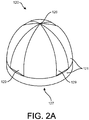
- FIGs. 2A , 2B, and 2C illustrate, via a top perspective view, a bottom perspective view, and a bottom view, respectively, features of a lid 120 of a storage container 100 not according to the present invention, consistent with implementations of the current subject matter.
- the view in FIG. 2C is from the bottom of the lid 120 into the inside of the lid.
- the lid 120 may be of a generally domed shape (with a wider portion at the bottom of the lid 120 and a more narrow portion at the top), although the lid is not limited to such a shape and other shapes (such as cubes, for example) may be utilized.
- the lid 120 has a lid sidewall 121 extending from a lid top 126.
- An inner lid region 127 is defined by the lid sidewall 121.
- the lid 120 has a bottom edge 124, which may be a flat edge.
- one or more grooves or indentations 129 may be formed in the lid sidewall 121, which in some circumstances could allow for more easily gripping the lid 120. As shown, the indentations 129 may not extend the entire length of the lid sidewall 121, creating a lipped region along a bottom portion of the lid sidewall 121.
- the lid sidewall 121 may form a third circular perimeter having a third diameter at a bottom portion of the lid sidewall 121.
- the third diameter is equal to that of the first diameter of the first circular perimeter of the bottom portion 112 of the base sidewall 111, so that the base sidewall 111 and the lid sidewall 121 can be aligned via their respective circular perimeters (e.g., that of the bottom portion 112 of the base sidewall 111at the flat shelf region 114 -- and the bottom portion 124 of the lid sidewall 121).
- the lid sidewall 121 includes a lid coupling feature 125, which as shown in FIG. 2B may be one or more threaded portions 125 extending around at least a portion of an inner portion of the lid sidewall 121.
- the lid coupling feature 125 releasably couples to the base coupling feature 115 to thereby releasably couple the lid 120 to the base 110.
- the threaded portions 115, 125 may be threaded or interlocked together by twisting the lid 120 and the base 110 together.
- a seal between the lid 120 and the base 110 may be waterproof, such that when the lid 120 is engaged with the base 110, no water or other fluid leaks through.
- the seal can be made waterproof by using a rubber gasket, ensuring the connection between the lid 120 and the base 110 is tight such that no water or other fluid may pass, or using other methods to make the connection waterproof.
- the post 118 is contained within the inner base region 117 and the inner lid region 127 when the lid 120 and the base 110 are coupled together (e.g., when the threads 115, 125 are interlocked), with the lid bottom (e.g., bottom portion 124) of the lid 120 resting on and aligned with the shelf region 114 of the base sidewall 111 of the base 110.
- an inner protrusion or downward extending edge 122 may be provided or formed on an inner top portion of the lid 120.
- the inner protrusion 122 may substantially be a ring formed on the inner top portion of the lid 120, sized for a top edge of the post 118 to fit within.
- FIGs. 3A and 3B illustrate, via a top perspective view and a side cross-sectional view, respectively, features of a storage container 100 not according to the present invention, consistent with implementations of the current subject matter.
- rings may be placed over the post 118 and may rest within the inner base region 117.
- the inner protrusion 122 (as shown in FIG. 3B ) prevents the rings from sliding off the post 118.
- the post 118 may be in close proximity to or adjacent to the inner top surface of the lid 120, preventing the rings from sliding off of the post 118.
- FIG. 3B illustrates the base 110 and the lid 120 coupled together via interlocking of the threads 115, 125.
- FIG. 3B is a cut-out portion or groove 150.
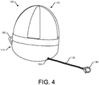
- FIG. 4 illustrates features of an assembled storage container 100 not according to the present invention.
- the groove 150 is formed into the base 110 and allows for a chain 130 (or other extending cable, such as a strap, rope, or the like) to extend from the base 110.
- the chain 130 may be made of any suitable material, such as, for example and not limitation, rope, leather, silver (sterling or plated), gold (solid gold or plated), string, tape, magnet, chain links, copper, platinum, stainless steel, rhodium, metal alloy, synthetic leather, or other synthetic material, as well as natural fibers (wool, silk, etc.), or various combinations thereof.
- suitable material such as, for example and not limitation, rope, leather, silver (sterling or plated), gold (solid gold or plated), string, tape, magnet, chain links, copper, platinum, stainless steel, rhodium, metal alloy, synthetic leather, or other synthetic material, as well as natural fibers (wool, silk, etc.), or various combinations thereof.
- a clasp 140 (or other connecting component, such as, for example and not limitation, a keychain loop, a spring ring clasp, a lobster (swivel) clasp, a barrel clasp, a toggle clasp, a magnetic clasp, a hook or "S" clasp, a fishhook clasp, a side lock clasp, an adjustable clasp, a ball and joint clasp, a bead clasp, a box (or tab) insert clasp, a button toggle clasp, a crimping clasp, a filigree clasp, a screw clasp, a slide lock clasp, a tab lock clasp, or a twister clasp) is secured or attached to an end of the chain 130. This allows for the storage container 100 to be securely and removably attached to a belt loop, key ring, purse, gym bag, or other personal storage item.
- the linking component 160 may be a flexible and/or bendable material that allows for the base 110 and the lid 120 to stay together (e.g., in one place) even when not directly coupled together via coupling features (e.g., threads) 115, 125.
- coupling features e.g., threads
- FIG. 5 illustrates features of a storage container 200 not according to the present invention, consistent with additional implementations of the current subject matter.
- the storage container 200 includes a base 210 with base sidewall 211 extending upward from a base bottom plate 216.
- the base sidewall 211 define an inner base region 217.
- a post 218 extends vertically upwardly from a bottom portion of the base 210.
- the base sidewall 211 forms a first circular perimeter having a first diameter at a top edge of the base sidewall (a shelf region 214).
- a lid 220 of the storage container 200 has a lid sidewall 221 extending from a lid top 226.
- An inner lid region 227 is defined by the lid sidewall 221.
- the lid 220 has a bottom edge 224, which may be a flat edge.
- the lid sidewall 221 forms a third circular perimeter having a third diameter equal to that of the first diameter of the base sidewall 211.
- the post 218 is contained within the inner base region 217 and the inner lid region 227 when the lid 220 and the base 210 are coupled together, with the lid bottom (e.g., bottom portion 224) of the lid 220 resting on and aligned with the shelf region 214 of the base sidewall 211.
- the base 210 and the lid 220 have one or more coupling features that allow for the base 210 and the lid 220 to be coupled together.
- a hook 202 (the lid coupling feature) may couple with an eye 201 (the base coupling feature).
- eye 201 the base coupling feature
- the storage container consistent with implementations of the current subject matter is not limited to such a fastener.
- an appropriately sized lock and key may be incorporated.
- the shelf region 214 and the bottom edge 224 of the lid may form a magnetic attachment to secure the lid 220 and the base 210.
- Other suitable fastening components in any combination, could also be used, such as Velcro, snaps, a zipper, metal clasp, button, or the like.
- FIG. 6 illustrates features of a base 310 of a storage container consistent with additional implementations of the current subject matter.
- the base 310 is similar to the base 110 described above, with base sidewall 311 with sidewall portions 312 and 313 with flat shelf region 314 extending therebetween.
- the base sidewall 311 extends from a base plate or bottom 316 and defines an inner base region 317.
- a base coupling feature 315 is provided for coupling with a lid.
- a groove 350 is provided from which a chain or other extending cable may extend to secure (with a clasp or other connecting component).
- a post 318 extends vertically upward from a bottom portion of the base 310.
- One or more separators 302a,b,c are provided at various positons along the length of the post 318 to separate a plurality of rings from one another for extra protection of the rings.
- the separators 302a,b,c may be formed of a flexible yet resilient material (e.g., foam or a soft rubber) that deforms to allow for a ring to slide over but that provides sufficient support to hold a ring thereon.
- the separators 302a,b,c may be fixed to the post 318 or may be removable and/or adjustable.
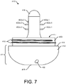
- FIG. 7 illustrates features of a base 410 of a storage container consistent with yet additional implementations of the current subject matter.
- the base 410 is similar to the base 110 described above, with base sidewall 411 with sidewall portions 412 and 413 with flat shelf region 414 extending therebetween.
- the base sidewall 411 extends from a base plate or bottom 416 and defines an inner base region 417.
- a base coupling feature 415 is provided for coupling with a lid.
- a groove 450 is provided from which a chain or other extending cable may extend to secure (with a clasp or other connecting component).
- a post 418 extends vertically upward from a bottom portion of the base 410.
- One or more pairs of protruding separators 402a-1,2, 402b-1,2, 402c-1,2, as shown in FIG. 7 may be provided at various positions along the length of the post 418 to separate one or more rings from one another. While three pairs of protruding separators are shown, fewer or more may be provided, such as one, two, four, five, or the like. Moreover, instead of pairs of protruding separators, a single separator or a separator with a plurality of components may be utilized. The pairs of protruding separators may fit within a portion of the post 418 and may extend perpendicularly outward from the post 418 upon depression of the appropriate separators.
- a subsequent depression of the appropriate separators may then cause the separators to again be fitted within the post 418.
- a first pair of protruding separators 402a-1,2 are shown mostly contained or fitted within the post 418, while two other pairs (402b-1,2 and 402c-1,2) are shown extended outward to hold one or more rings on the protruding portions.
- FIGs. 8A and 8B illustrates features, via side cross-sectional views, of bases 810 and 910 with respective removable posts 818 and 918, consistent with additional implementations not according to the present invention, of the current subject matter.
- one or more posts may be removable so that posts of varying diameters, to accommodate rings of different sizes, can be attached to the base.
- Such a removable connection may include, for example with reference to FIG. 8A , a screw-like component 828 at a bottom edge of the post 818 to screw into and out of a threaded recess 838 formed within a bottom portion of the base 810.
- FIG. 8B illustrates another implementation for a removable post 918 in which a circular cut-out attachment 928 with multiple tabs is positioned on the bottom of the post 918.
- the attachment 928 fits into a corresponding circular cut-out recess 938, also with multiple tabs.
- the post 918 snaps into the base 910 after a snap and turn placement, the tabs of the post 918 interlocking with the tabs of the base 910.
- Other suitable removable connections could be implemented.
- the base and the lid of the ring storage container may be made from various structurally sound materials, such as, for example and not limitation, plastic, hard rubber, or other synthetic materials.
- a waterproof covering may be provided over the outer surfaces of the base and the lid.
- Other coverings may instead be provided, such as a leather skin, a linen covering, a nylon covering, etc.
- the coverings, or the base and the lid themselves, may be colored or textured as desired.
- the ring storage container may include a cleaning solution storage and applicator, for emitting a cleaning solution when the base and the lid are coupled together.
- a cleaning solution storage and applicator may be contained within the base or top portion, and an external button or the like may cause the cleaning solution to be emitted.
- a ring storage container consistent with implementations of the current subject matter may include a Bluetooth chip or the like so that a location of the ring storage container can be determined.
- FIG. 5 or other locking mechanisms such as a latch, screw, clasp, magnets, or the like
- FIGs. 1A-3B could be combined with the threaded coupling features shown in FIGs. 1A-3B .
- a ring storage container in accordance with implementations of the current subject matter provides a personal ring holder for use when it may be desirable (e.g., at a nail salon, at the gym, at an airport, when washing hands or changing a diaper, etc.) for one or more individuals to remove and store their rings or other small personal items.
- a ring storage container consistent with implementations described herein may include a variety of sizes (e.g., small, medium, large) to hold fewer rings (small size) or more rings (large size), with each of the components sized accordingly. Additionally, the thickness of the sides (e.g., the sidewalls) may vary, with some of the ring storage containers having thicker walls than others.
- the thickness of the walls may depend on, for example, the material being used and/or the type of coupling features.
- the ring storage container can be shockproof such that if the ring storage container is dropped, the stored ring(s) or other small personal items are not damaged.
- phrases such as "at least one of' or “one or more of' may occur followed by a conjunctive list of elements or features.
- the term “and/or” may also occur in a list of two or more elements or features. Unless otherwise implicitly or explicitly contradicted by the context in which it used, such a phrase is intended to mean any of the listed elements or features individually or any of the recited elements or features in combination with any of the other recited elements or features.
- the phrases “at least one of A and B;” “one or more of A and B;” and “A and/or B” are each intended to mean "A alone, B alone, or A and B together.”
- a similar interpretation is also intended for lists including three or more items.
- phrases “at least one of A, B, and C;” “one or more of A, B, and C;” and “A, B, and/or C” are each intended to mean “A alone, B alone, C alone, A and B together, A and C together, B and C together, or A and B and C together.”
- Use of the term “based on,” above and in the claims is intended to mean, “based at least in part on,” such that an unrecited feature or element is also permissible.
- the device may be otherwise oriented (rotated 90 degrees or at other orientations) and the spatially relative descriptors used herein interpreted accordingly.
- the terms “upwardly”, “downwardly”, “vertical”, “horizontal” and the like are used herein for the purpose of explanation only unless specifically indicated otherwise.
- first and second may be used herein to describe various features/elements (including steps), these features/elements should not be limited by these terms, unless the context indicates otherwise. These terms may be used to distinguish one feature/element from another feature/element. Thus, a first feature/element discussed below could be termed a second feature/element, and similarly, a second feature/element discussed below could be termed a first feature/element without departing from the teachings provided herein.
- a numeric value may have a value that is +/- 0.1% of the stated value (or range of values), +/- 1% of the stated value (or range of values), +/- 2% of the stated value (or range of values), +/- 5% of the stated value (or range of values), +/- 10% of the stated value (or range of values), etc.
- Any numerical values given herein should also be understood to include about or approximately that value, unless the context indicates otherwise. For example, if the value "10" is disclosed, then “about 10" is also disclosed. Any numerical range recited herein is intended to include all sub-ranges subsumed therein.
Landscapes
- Engineering & Computer Science (AREA)
- Mechanical Engineering (AREA)
- Closures For Containers (AREA)
Claims (19)
- Boîtier de rangement destiné à maintenir de manière sûre une ou plusieurs bagues personnelles, telles que des boucles d'oreilles ou des bagues de doigt, et/ou d'autres petits objets personnels, comprenant :une base (110) comprenant une région de base intérieure (117) définie par une paroi latérale de base (111) s'étendant à partir d'une plaque de base (116), la paroi latérale de base (111) comprenant un élément d'accouplement de base (115), la base (110) comprenant en outre une tige (118) s'étendant verticalement vers le haut à partir de la région de base intérieure (117) et destinée à maintenir une ou plusieurs bagues sur celle-ci ; etun couvercle (120) comprenant une région de couvercle intérieure (127) définie par une paroi latérale de couvercle (121) s'étendant à partir d'une partie supérieure de couvercle (126), la paroi latérale de couvercle (121) comprenant un élément d'accouplement de couvercle (125) accouplé de façon détachable à l'élément d'accouplement de base (115) pour ainsi accoupler le couvercle (120) de façon détachable à la base (110) ;dans lequel la tige (118) est contenue dans la région de base intérieure (117) et la région de couvercle intérieure (127) lorsque le couvercle (120) et la base (110) sont accouplés entre eux ;caractérisé en ce queun ou plusieurs organes de séparation (302) sont respectivement formés autour d'une circonférence de la tige (118), les un ou plusieurs organes de séparation (302) étant configurés pour maintenir l'une ou plusieurs des une ou plusieurs bagues à un position respective le long de la tige.
- Boîtier de rangement selon la revendication 1, dans lequel l'élément d'accouplement de base (115) comprend une partie filetée s'inter-verrouillant avec une partie filetée opposée (125) de l'élément d'accouplement du couvercle (120).
- Boîtier de rangement selon la revendication 1, dans lequel la paroi latérale de base (111) forme un premier périmètre circulaire (112) présentant un premier diamètre et un deuxième périmètre circulaire (113) présentant un deuxième diamètre inférieur au premier diamètre, et dans lequel le premier périmètre circulaire (112) et le deuxième périmètre circulaire (113) sont reliés par une région de plateau (114).
- Boîtier de rangement selon la revendication 3, dans lequel l'élément d'accouplement de base (115) est positionné sur le deuxième périmètre circulaire (113).
- Boîtier de rangement selon la revendication 3, dans lequel un fond de couvercle (124) du couvercle (120) repose sur la région de plateau (114) de la paroi latérale de base (111) lorsque le couvercle (120) et la base (110) sont accouplés entre eux.
- Boîtier de rangement selon la revendication 5, dans lequel la paroi latérale de couvercle (121) forme un troisième périmètre circulaire présentant un troisième diamètre égal au premier diamètre.
- Boîtier de rangement selon la revendication 6, dans lequel le premier périmètre circulaire (112) et le troisième périmètre circulaire sont alignés lorsque le couvercle (120) et la base (110) sont accouplés entre eux.
- Boîtier de rangement selon la revendication 1, dans lequel la paroi latérale de base (111) forme un premier périmètre circulaire présentant un premier diamètre et la paroi latérale de couvercle (121) forme un troisième périmètre circulaire présentant un troisième diamètre égal au premier diamètre.
- Boîtier de rangement selon la revendication 8, dans lequel, lorsque le couvercle (120) et la base (110) sont accouplés entre eux, le premier périmètre circulaire et le troisième périmètre circulaire sont alignés.
- Boîtier de rangement selon la revendication 1, dans lequel une ouverture (150) à partir de laquelle s'étend une chaîne (130) avec un organe de raccordement (140) est formée dans une partie de la paroi latérale de base (111) .
- Boîtier de rangement selon la revendication 1, dans lequel une saillie intérieure (122) est formée sur une partie supérieure intérieure du couvercle (120), la saillie intérieure (122) étant dimensionnée de manière à permettre à un bord supérieur de la tige (118) de s'ajuster dans celle-ci.
- Boîtier de rangement selon la revendication 1, dans lequel une pluralité d'indentations (129) sont formées autour d'une circonférence du couvercle (120) dans la paroi latérale de couvercle (121).
- Boîtier de rangement selon la revendication 1, comprenant en outre un organe de liaison flexible (160), dans lequel une première extrémité de l'organe de liaison flexible est fixée à la paroi latérale de base (111) et une deuxième extrémité de l'organe de liaison flexible est fixée à la paroi latérale de couvercle (121), l'organe de liaison flexible (160) étant configuré pour maintenir la base (110) et le couvercle (120) ensemble.
- Boîtier de rangement selon la revendication 1, dans lequel la paroi latérale de base (111) comprend en outre un deuxième élément d'accouplement de base (201) et la paroi latérale de couvercle (121) comprend en outre un deuxième élément d'accouplement de couvercle (202) accouplé de façon détachable au deuxième élément d'accouplement de base.
- Boîtier de rangement selon la revendication 1, dans lequel la tige (118) peut être retirée depuis la région de base intérieure (117) de la base (110).
- Boîtier de rangement destiné à maintenir de manière sûre une ou plusieurs bagues, telles que des boucles d'oreille ou des bagues de doigt, et/ou d'autres petits objets personnels, comprenant :une base (110) comprenant une région de base intérieure (117) définie par une paroi latérale de base (111) s'étendant à partir d'une plaque de base (116), la paroi latérale de base (111) formant un premier périmètre circulaire (112) présentant un premier diamètre et un deuxième périmètre circulaire (113) présentant un deuxième diamètre inférieur au premier diamètre, dans lequel le premier périmètre circulaire et le deuxième périmètre circulaire sont reliés par une région de plateau (114), dans lequel la paroi latérale de base (111) comprend un élément d'accouplement de base fileté (115) sur le deuxième périmètre circulaire (113), et la base (110) comprenant en outre une tige (118) s'étendant verticalement vers le haut à partir de la région de base intérieure (117) pour maintenir les une ou plusieurs bagues sur celle-ci ;un couvercle (120) comprenant une région de couvercle intérieure (127) définie par une paroi latérale de couvercle (121) s'étendant à partir d'une partie supérieure de couvercle (126), la paroi latérale de couvercle (121) formant un troisième périmètre circulaire présentant un troisième diamètre égal au premier diamètre, et la paroi latérale de couvercle (121) comprenant un élément d'accouplement de couvercle fileté (125) accouplé de façon détachable à l'élément d'accouplement de base fileté (115) pour ainsi accoupler le couvercle (120) de façon détachable à la base (110) par une action d'interverrouillage ;dans lequel la tige (118) est contenue dans la région de base intérieure (117) et la région de couvercle intérieure (127) lorsque le couvercle (120) et la base (110) sont accouplés entre eux ; etdans lequel un fond de couvercle (124) du couvercle (120) repose sur la région de plateau (114) de la paroi latérale de base (111) lorsque le couvercle (120) et la base (110) sont accouplés entre eux, alignant le premier périmètre circulaire et le troisième périmètre circulaire,caractérisé en ce qu'un ou plusieurs organes de séparation sont formés respectivement autour d'une circonférence de la tige, les un ou plusieurs organes de séparation étant configurés pour maintenir l'une ou plusieurs des une ou plusieurs bagues à une position respective le long de la tige.
- Procédé comprenant :le raccordement d'une base (110) d'un boîtier de rangement (100) destiné à maintenir de manière sûre une ou plusieurs bagues personnelles, telles que des boucles d'oreille ou des bagues à doigt, et/ou d'autres petits objets personnels, à un couvercle (120) du boîtier de rangement (100) pour enfermer une ou plusieurs bagues dans le boîtier de rangement (100) ;dans lequel la base comprend une région de base intérieure (117) définie par une paroi latérale de base (111) s'étendant à partir d'une plaque de base (116), la paroi latérale de base (111) comprenant un élément d'accouplement de base (115), la base comprenant en outre une tige (118) s'étendant verticalement vers le haut à partir de la région de base intérieure (117) pour maintenir une ou plusieurs bagues sur celle-ci ;dans lequel le couvercle (120) comprend une région de couvercle intérieure (127) définie par une paroi latérale de couvercle (121) s'étendant à partir d'une partie supérieure de couvercle (126), la paroi latérale de couvercle (121) comprenant un élément d'accouplement de couvercle (125) accouplé de façon détachable à l'élément d'accouplement de base (115) ;dans lequel le raccordement comprend l'accouplement de l'élément d'accouplement de base (115) et de l'élément d'accouplement de couvercle (125) entre eux ; etdans lequel les une ou plusieurs bagues sont maintenues sur la tige (118), dans lequel le tige (118) est contenue dans la région de base intérieure (117) et la région de couvercle intérieure (127) lorsque le couvercle (120) et la base (110) sont accouplés entre eux,dans lequel un ou plusieurs organes de séparation sont formés respectivement autour d'une circonférence de la tige, les un ou plusieurs organes de séparation étant configurés pour maintenir l'une ou plusieurs des une ou plusieurs bagues à une position respective le long de la tige.
- Procédé selon la revendication 17, dans lequel une pluralité d'indentations (129) sont formées autour d'une circonférence du couvercle (120) dans la paroi latérale de couvercle (121), dans lequel le raccordement comprend en outre l'utilisation de la pluralité d'indentations (129) pour l'accouplement de l'élément d'accouplement de base (115) et de l'élément d'accouplement de couvercle (125) entre eux.
- Procédé selon la revendication 17, dans lequel l'élément d'accouplement de base (115) comprend une partie filetée s'inter-verrouillant avec une partie filetée opposée de l'élément d'accouplement de couvercle (125), dans lequel l'accouplement de l'élément d'accouplement de base (115) et de l'élément d'accouplement de couvercle (125) entre eux comprend :l'alignement de la partie filetée et de la partie filetée opposée ; etla rotation du couvercle (120) sur la base (110).
Applications Claiming Priority (2)
| Application Number | Priority Date | Filing Date | Title |
|---|---|---|---|
| US201762499180P | 2017-01-17 | 2017-01-17 | |
| PCT/US2018/014087 WO2018136543A1 (fr) | 2017-01-17 | 2018-01-17 | Contenant de stockage de bagues |
Publications (2)
| Publication Number | Publication Date |
|---|---|
| EP3570700A1 EP3570700A1 (fr) | 2019-11-27 |
| EP3570700B1 true EP3570700B1 (fr) | 2021-09-15 |
Family
ID=61599570
Family Applications (1)
| Application Number | Title | Priority Date | Filing Date |
|---|---|---|---|
| EP18709820.7A Not-in-force EP3570700B1 (fr) | 2017-01-17 | 2018-01-17 | Contenant de stockage de bagues |
Country Status (4)
| Country | Link |
|---|---|
| US (3) | US10729216B2 (fr) |
| EP (1) | EP3570700B1 (fr) |
| CA (1) | CA3050102A1 (fr) |
| WO (1) | WO2018136543A1 (fr) |
Families Citing this family (13)
| Publication number | Priority date | Publication date | Assignee | Title |
|---|---|---|---|---|
| USD911701S1 (en) * | 2016-09-12 | 2021-03-02 | Beast Enterprises, LLC | Mouth guard cleaning and storage device |
| WO2018136543A1 (fr) * | 2017-01-17 | 2018-07-26 | Schafer Kimberly Ann | Contenant de stockage de bagues |
| USD876131S1 (en) * | 2017-12-08 | 2020-02-25 | Spectrum Diversified Designs, Llc | Ring bowl |
| US10779621B2 (en) * | 2018-06-01 | 2020-09-22 | Hans Nygren | Protective ring case |
| USD953741S1 (en) * | 2019-06-13 | 2022-06-07 | Abdul Khan | String light storage container |
| USD981066S1 (en) | 2019-11-27 | 2023-03-14 | Watkins-Conti Products, Inc. | Base for a vaginal device |
| USD979924S1 (en) * | 2019-11-27 | 2023-03-07 | Watkins-Conti Products, Inc. | Two-part container for a vaginal device |
| USD945112S1 (en) * | 2020-09-30 | 2022-03-08 | James H. Rowe | Bun |
| USD965799S1 (en) * | 2021-06-29 | 2022-10-04 | Ah License Aps | Pacifier holder |
| USD1011746S1 (en) * | 2021-11-05 | 2024-01-23 | Michael A Ponte | Case for storing articles |
| USD1027440S1 (en) * | 2022-03-14 | 2024-05-21 | Connie Cordero | Respirator protector case |
| USD1016480S1 (en) * | 2022-06-27 | 2024-03-05 | Zhejiang Yanyang Technology Co., Ltd. | Storage box |
| USD1052895S1 (en) * | 2024-08-14 | 2024-12-03 | Weiquan Zheng | Jewelry travel case |
Family Cites Families (40)
| Publication number | Priority date | Publication date | Assignee | Title |
|---|---|---|---|---|
| US657250A (en) * | 1900-03-21 | 1900-09-04 | Albert B Pratt | Carton or shipping-package for piston-packings. |
| GB190928538A (en) * | 1909-12-07 | 1910-09-01 | Edward Whitnear | Combined Means for Holding Pins, and Means for Holding a Ring or Rings. |
| US2963149A (en) * | 1958-05-19 | 1960-12-06 | Bergh Bros Co | Jewelry display device |
| US2978110A (en) * | 1960-01-07 | 1961-04-04 | Lewis S Haskins | Rack-like holder for small articles |
| US3540576A (en) * | 1968-12-26 | 1970-11-17 | Parker Hannifin Corp | Storage and display device for packing rings |
| US3937324A (en) * | 1974-02-04 | 1976-02-10 | Creative Tools, Inc. | Container for marine storage of tools |
| US3978761A (en) * | 1975-06-26 | 1976-09-07 | Thomas & Betts Corporation | Fastener assembly |
| US4341300A (en) * | 1979-12-31 | 1982-07-27 | Royal Hinge & Die Co., Inc. | Article holder and method of manufacture thereof |
| USD275638S (en) * | 1981-10-29 | 1984-09-25 | Grier Rachel A | Toothpick holder |
| USD279145S (en) * | 1983-05-18 | 1985-06-11 | Jacmel Jewelry, Inc. | Jewelry box |
| US4552264A (en) * | 1984-03-27 | 1985-11-12 | General Mills Products Corp. | Jewelry container |
| US5035319A (en) * | 1990-06-07 | 1991-07-30 | Kunisch Hans P | Jewelry storage case |
| JPH0523208A (ja) * | 1991-07-19 | 1993-02-02 | Misawa Homes Co Ltd | 指輪保持具 |
| DE9406943U1 (de) * | 1994-04-26 | 1994-07-14 | Yang, Teng-Feng, Pa-Te, Tao-Yuan | Zusammenklappbarer mehrschichtiger Behälter |
| US5547072A (en) * | 1994-06-03 | 1996-08-20 | Kaiser; Burton | Jewelry box with removable display platform |
| DE29502288U1 (de) | 1995-02-13 | 1995-04-13 | Rösler, Peter, 88239 Wangen | Verpackungsbehälter für ringförmige Bauelemente |
| US5649625A (en) * | 1995-06-05 | 1997-07-22 | Ovadia; Joseph | Ring tray with nesting ring supports |
| USD455552S1 (en) * | 1999-08-16 | 2002-04-16 | Tony M. Charness | Belt case |
| US7121405B2 (en) * | 2002-11-22 | 2006-10-17 | Taiyo Yuden Co., Ltd. | Disc package |
| US7367449B2 (en) * | 2003-01-21 | 2008-05-06 | Kaminski Scott T | Case with two sides and interlocking latch |
| US8307982B1 (en) * | 2003-08-18 | 2012-11-13 | Pwp Industries, Inc. | Cake container cover-base connection |
| USD509655S1 (en) * | 2004-06-01 | 2005-09-20 | Samuel D. Barnes | Spinner bait box |
| USD561992S1 (en) * | 2006-04-29 | 2008-02-19 | Lee Linsley | Novelty message capsule |
| US20090107856A1 (en) * | 2007-10-29 | 2009-04-30 | Jacquelyn Louise Egnatic | Jewelry cleaning unit |
| US7841468B2 (en) * | 2007-11-08 | 2010-11-30 | Robert Bosch Gmbh | Accessory holder |
| US20090127138A1 (en) * | 2007-11-17 | 2009-05-21 | Soraya Allameh | Jewelry display |
| USD588361S1 (en) * | 2008-01-17 | 2009-03-17 | Rose Plastic Usa, L.P. | Impact resistant container |
| US8522964B1 (en) | 2011-01-06 | 2013-09-03 | Patricka S. Pledger | Jewelry storage case |
| USD682675S1 (en) * | 2011-04-07 | 2013-05-21 | Gino Rapparini | Reinforced-ring container for beverage-making products |
| USD675439S1 (en) * | 2011-05-27 | 2013-02-05 | Hubbell Incorporated | Storage container for electrical components |
| CN202085889U (zh) * | 2011-05-30 | 2011-12-28 | 邓英卫 | 一种饰品盒 |
| USD738111S1 (en) * | 2013-05-16 | 2015-09-08 | Greg Otto | Combined stackable container and lid |
| USD740029S1 (en) * | 2013-05-16 | 2015-10-06 | Greg Otto | Combined stackable container and lid |
| US9314079B2 (en) * | 2013-11-01 | 2016-04-19 | Triple BBB's, LLC | Device, systems, and methods for holding objects |
| CH709172A1 (de) * | 2014-01-21 | 2015-07-31 | Hoffmann Neopac Ag | Behälter mit Verschlusskappe und Garantiering. |
| CN204105129U (zh) * | 2014-04-11 | 2015-01-21 | 于震宇 | 一种首饰整理箱 |
| KR20160123735A (ko) * | 2015-04-17 | 2016-10-26 | 주식회사 화인쥬얼리 | 물품보관이 가능한 목걸이 |
| US11122874B2 (en) * | 2015-07-03 | 2021-09-21 | Lerin Lockwood | Retention device |
| US10299611B1 (en) * | 2015-09-24 | 2019-05-28 | Kathryn O'Malley | Stackable jewelry organizer and method of use |
| WO2018136543A1 (fr) * | 2017-01-17 | 2018-07-26 | Schafer Kimberly Ann | Contenant de stockage de bagues |
-
2018
- 2018-01-17 WO PCT/US2018/014087 patent/WO2018136543A1/fr not_active Ceased
- 2018-01-17 CA CA3050102A patent/CA3050102A1/fr active Pending
- 2018-01-17 US US15/873,691 patent/US10729216B2/en active Active
- 2018-01-17 US US29/634,019 patent/USD865362S1/en active Active
- 2018-01-17 EP EP18709820.7A patent/EP3570700B1/fr not_active Not-in-force
-
2020
- 2020-05-12 US US15/930,233 patent/US10980323B2/en active Active
Also Published As
| Publication number | Publication date |
|---|---|
| USD865362S1 (en) | 2019-11-05 |
| US10980323B2 (en) | 2021-04-20 |
| WO2018136543A1 (fr) | 2018-07-26 |
| CA3050102A1 (fr) | 2018-07-26 |
| US20200268119A1 (en) | 2020-08-27 |
| US10729216B2 (en) | 2020-08-04 |
| US20180199685A1 (en) | 2018-07-19 |
| EP3570700A1 (fr) | 2019-11-27 |
Similar Documents
| Publication | Publication Date | Title |
|---|---|---|
| US10980323B2 (en) | Ring storage container | |
| US6318548B1 (en) | Easily transported contact lens care kit | |
| US9532639B2 (en) | Customizable carrier for a portable electronic device | |
| US6685023B2 (en) | Case for flexible elongated objects | |
| US20110062203A1 (en) | Disk carrier and method | |
| US20070044512A1 (en) | Interchangeable jewellery insert and item for receiving the insert | |
| US9635917B2 (en) | Device, systems, and methods for holding objects | |
| US20170349327A1 (en) | Magnetic holder | |
| CN114096150A (zh) | 诱饵容器 | |
| US20180146754A1 (en) | Portable Secure Carrier Arrangement | |
| US20050109803A1 (en) | Water bottle holder | |
| US20160206123A1 (en) | Bottle holder | |
| WO2025240373A1 (fr) | Contenant à bijou de voyage modulaire | |
| US6253944B1 (en) | Sport luggage | |
| US7137914B1 (en) | Ball with receptacle to receive a key | |
| US20240081498A1 (en) | Mobile Device Carrying Device | |
| US9066611B1 (en) | Jewelry organizer | |
| JP2006514905A (ja) | 可撓細長物品のためのケース | |
| CN218457531U (zh) | 串珠盘 | |
| US10609999B2 (en) | Hair elastic accessory | |
| US20140291364A1 (en) | Clip-On Pill Holder | |
| WO2007022632A1 (fr) | Incrustation de bijou interchangeable et article de reception de l'incrustation | |
| CN110466874A (zh) | 瓶子及便携式装置 | |
| KR200239465Y1 (ko) | 스트랩의 호환성이 있는 연결구용 수납구 및 그 수납구에끼워지는 호환성이 있는 연결구용 고정구 | |
| KR200376604Y1 (ko) | 물병 휴대 고리 |
Legal Events
| Date | Code | Title | Description |
|---|---|---|---|
| STAA | Information on the status of an ep patent application or granted ep patent |
Free format text: STATUS: UNKNOWN |
|
| STAA | Information on the status of an ep patent application or granted ep patent |
Free format text: STATUS: THE INTERNATIONAL PUBLICATION HAS BEEN MADE |
|
| PUAI | Public reference made under article 153(3) epc to a published international application that has entered the european phase |
Free format text: ORIGINAL CODE: 0009012 |
|
| STAA | Information on the status of an ep patent application or granted ep patent |
Free format text: STATUS: REQUEST FOR EXAMINATION WAS MADE |
|
| 17P | Request for examination filed |
Effective date: 20190819 |
|
| AK | Designated contracting states |
Kind code of ref document: A1 Designated state(s): AL AT BE BG CH CY CZ DE DK EE ES FI FR GB GR HR HU IE IS IT LI LT LU LV MC MK MT NL NO PL PT RO RS SE SI SK SM TR |
|
| AX | Request for extension of the european patent |
Extension state: BA ME |
|
| DAV | Request for validation of the european patent (deleted) | ||
| DAX | Request for extension of the european patent (deleted) | ||
| GRAP | Despatch of communication of intention to grant a patent |
Free format text: ORIGINAL CODE: EPIDOSNIGR1 |
|
| STAA | Information on the status of an ep patent application or granted ep patent |
Free format text: STATUS: GRANT OF PATENT IS INTENDED |
|
| INTG | Intention to grant announced |
Effective date: 20210412 |
|
| GRAS | Grant fee paid |
Free format text: ORIGINAL CODE: EPIDOSNIGR3 |
|
| GRAA | (expected) grant |
Free format text: ORIGINAL CODE: 0009210 |
|
| STAA | Information on the status of an ep patent application or granted ep patent |
Free format text: STATUS: THE PATENT HAS BEEN GRANTED |
|
| AK | Designated contracting states |
Kind code of ref document: B1 Designated state(s): AL AT BE BG CH CY CZ DE DK EE ES FI FR GB GR HR HU IE IS IT LI LT LU LV MC MK MT NL NO PL PT RO RS SE SI SK SM TR |
|
| REG | Reference to a national code |
Ref country code: CH Ref legal event code: EP |
|
| REG | Reference to a national code |
Ref country code: DE Ref legal event code: R096 Ref document number: 602018023566 Country of ref document: DE |
|
| REG | Reference to a national code |
Ref country code: IE Ref legal event code: FG4D |
|
| REG | Reference to a national code |
Ref country code: AT Ref legal event code: REF Ref document number: 1429833 Country of ref document: AT Kind code of ref document: T Effective date: 20211015 |
|
| REG | Reference to a national code |
Ref country code: LT Ref legal event code: MG9D |
|
| REG | Reference to a national code |
Ref country code: NL Ref legal event code: MP Effective date: 20210915 |
|
| PG25 | Lapsed in a contracting state [announced via postgrant information from national office to epo] |
Ref country code: RS Free format text: LAPSE BECAUSE OF FAILURE TO SUBMIT A TRANSLATION OF THE DESCRIPTION OR TO PAY THE FEE WITHIN THE PRESCRIBED TIME-LIMIT Effective date: 20210915 Ref country code: SE Free format text: LAPSE BECAUSE OF FAILURE TO SUBMIT A TRANSLATION OF THE DESCRIPTION OR TO PAY THE FEE WITHIN THE PRESCRIBED TIME-LIMIT Effective date: 20210915 Ref country code: HR Free format text: LAPSE BECAUSE OF FAILURE TO SUBMIT A TRANSLATION OF THE DESCRIPTION OR TO PAY THE FEE WITHIN THE PRESCRIBED TIME-LIMIT Effective date: 20210915 Ref country code: FI Free format text: LAPSE BECAUSE OF FAILURE TO SUBMIT A TRANSLATION OF THE DESCRIPTION OR TO PAY THE FEE WITHIN THE PRESCRIBED TIME-LIMIT Effective date: 20210915 Ref country code: NO Free format text: LAPSE BECAUSE OF FAILURE TO SUBMIT A TRANSLATION OF THE DESCRIPTION OR TO PAY THE FEE WITHIN THE PRESCRIBED TIME-LIMIT Effective date: 20211215 Ref country code: BG Free format text: LAPSE BECAUSE OF FAILURE TO SUBMIT A TRANSLATION OF THE DESCRIPTION OR TO PAY THE FEE WITHIN THE PRESCRIBED TIME-LIMIT Effective date: 20211215 Ref country code: LT Free format text: LAPSE BECAUSE OF FAILURE TO SUBMIT A TRANSLATION OF THE DESCRIPTION OR TO PAY THE FEE WITHIN THE PRESCRIBED TIME-LIMIT Effective date: 20210915 |
|
| PGFP | Annual fee paid to national office [announced via postgrant information from national office to epo] |
Ref country code: FR Payment date: 20211125 Year of fee payment: 5 Ref country code: GB Payment date: 20211125 Year of fee payment: 5 |
|
| REG | Reference to a national code |
Ref country code: AT Ref legal event code: MK05 Ref document number: 1429833 Country of ref document: AT Kind code of ref document: T Effective date: 20210915 |
|
| PG25 | Lapsed in a contracting state [announced via postgrant information from national office to epo] |
Ref country code: LV Free format text: LAPSE BECAUSE OF FAILURE TO SUBMIT A TRANSLATION OF THE DESCRIPTION OR TO PAY THE FEE WITHIN THE PRESCRIBED TIME-LIMIT Effective date: 20210915 Ref country code: GR Free format text: LAPSE BECAUSE OF FAILURE TO SUBMIT A TRANSLATION OF THE DESCRIPTION OR TO PAY THE FEE WITHIN THE PRESCRIBED TIME-LIMIT Effective date: 20211216 |
|
| PG25 | Lapsed in a contracting state [announced via postgrant information from national office to epo] |
Ref country code: AT Free format text: LAPSE BECAUSE OF FAILURE TO SUBMIT A TRANSLATION OF THE DESCRIPTION OR TO PAY THE FEE WITHIN THE PRESCRIBED TIME-LIMIT Effective date: 20210915 |
|
| PGFP | Annual fee paid to national office [announced via postgrant information from national office to epo] |
Ref country code: DE Payment date: 20211124 Year of fee payment: 5 |
|
| PG25 | Lapsed in a contracting state [announced via postgrant information from national office to epo] |
Ref country code: IS Free format text: LAPSE BECAUSE OF FAILURE TO SUBMIT A TRANSLATION OF THE DESCRIPTION OR TO PAY THE FEE WITHIN THE PRESCRIBED TIME-LIMIT Effective date: 20220115 Ref country code: SM Free format text: LAPSE BECAUSE OF FAILURE TO SUBMIT A TRANSLATION OF THE DESCRIPTION OR TO PAY THE FEE WITHIN THE PRESCRIBED TIME-LIMIT Effective date: 20210915 Ref country code: SK Free format text: LAPSE BECAUSE OF FAILURE TO SUBMIT A TRANSLATION OF THE DESCRIPTION OR TO PAY THE FEE WITHIN THE PRESCRIBED TIME-LIMIT Effective date: 20210915 Ref country code: RO Free format text: LAPSE BECAUSE OF FAILURE TO SUBMIT A TRANSLATION OF THE DESCRIPTION OR TO PAY THE FEE WITHIN THE PRESCRIBED TIME-LIMIT Effective date: 20210915 Ref country code: PT Free format text: LAPSE BECAUSE OF FAILURE TO SUBMIT A TRANSLATION OF THE DESCRIPTION OR TO PAY THE FEE WITHIN THE PRESCRIBED TIME-LIMIT Effective date: 20220117 Ref country code: PL Free format text: LAPSE BECAUSE OF FAILURE TO SUBMIT A TRANSLATION OF THE DESCRIPTION OR TO PAY THE FEE WITHIN THE PRESCRIBED TIME-LIMIT Effective date: 20210915 Ref country code: NL Free format text: LAPSE BECAUSE OF FAILURE TO SUBMIT A TRANSLATION OF THE DESCRIPTION OR TO PAY THE FEE WITHIN THE PRESCRIBED TIME-LIMIT Effective date: 20210915 Ref country code: ES Free format text: LAPSE BECAUSE OF FAILURE TO SUBMIT A TRANSLATION OF THE DESCRIPTION OR TO PAY THE FEE WITHIN THE PRESCRIBED TIME-LIMIT Effective date: 20210915 Ref country code: EE Free format text: LAPSE BECAUSE OF FAILURE TO SUBMIT A TRANSLATION OF THE DESCRIPTION OR TO PAY THE FEE WITHIN THE PRESCRIBED TIME-LIMIT Effective date: 20210915 Ref country code: CZ Free format text: LAPSE BECAUSE OF FAILURE TO SUBMIT A TRANSLATION OF THE DESCRIPTION OR TO PAY THE FEE WITHIN THE PRESCRIBED TIME-LIMIT Effective date: 20210915 Ref country code: AL Free format text: LAPSE BECAUSE OF FAILURE TO SUBMIT A TRANSLATION OF THE DESCRIPTION OR TO PAY THE FEE WITHIN THE PRESCRIBED TIME-LIMIT Effective date: 20210915 |
|
| REG | Reference to a national code |
Ref country code: DE Ref legal event code: R097 Ref document number: 602018023566 Country of ref document: DE |
|
| PLBE | No opposition filed within time limit |
Free format text: ORIGINAL CODE: 0009261 |
|
| STAA | Information on the status of an ep patent application or granted ep patent |
Free format text: STATUS: NO OPPOSITION FILED WITHIN TIME LIMIT |
|
| PG25 | Lapsed in a contracting state [announced via postgrant information from national office to epo] |
Ref country code: DK Free format text: LAPSE BECAUSE OF FAILURE TO SUBMIT A TRANSLATION OF THE DESCRIPTION OR TO PAY THE FEE WITHIN THE PRESCRIBED TIME-LIMIT Effective date: 20210915 |
|
| 26N | No opposition filed |
Effective date: 20220616 |
|
| PG25 | Lapsed in a contracting state [announced via postgrant information from national office to epo] |
Ref country code: SI Free format text: LAPSE BECAUSE OF FAILURE TO SUBMIT A TRANSLATION OF THE DESCRIPTION OR TO PAY THE FEE WITHIN THE PRESCRIBED TIME-LIMIT Effective date: 20210915 Ref country code: MC Free format text: LAPSE BECAUSE OF FAILURE TO SUBMIT A TRANSLATION OF THE DESCRIPTION OR TO PAY THE FEE WITHIN THE PRESCRIBED TIME-LIMIT Effective date: 20210915 |
|
| REG | Reference to a national code |
Ref country code: CH Ref legal event code: PL |
|
| REG | Reference to a national code |
Ref country code: BE Ref legal event code: MM Effective date: 20220131 |
|
| PG25 | Lapsed in a contracting state [announced via postgrant information from national office to epo] |
Ref country code: LU Free format text: LAPSE BECAUSE OF NON-PAYMENT OF DUE FEES Effective date: 20220117 |
|
| PG25 | Lapsed in a contracting state [announced via postgrant information from national office to epo] |
Ref country code: BE Free format text: LAPSE BECAUSE OF NON-PAYMENT OF DUE FEES Effective date: 20220131 |
|
| PG25 | Lapsed in a contracting state [announced via postgrant information from national office to epo] |
Ref country code: LI Free format text: LAPSE BECAUSE OF NON-PAYMENT OF DUE FEES Effective date: 20220131 Ref country code: CH Free format text: LAPSE BECAUSE OF NON-PAYMENT OF DUE FEES Effective date: 20220131 |
|
| PG25 | Lapsed in a contracting state [announced via postgrant information from national office to epo] |
Ref country code: IT Free format text: LAPSE BECAUSE OF FAILURE TO SUBMIT A TRANSLATION OF THE DESCRIPTION OR TO PAY THE FEE WITHIN THE PRESCRIBED TIME-LIMIT Effective date: 20210915 Ref country code: IE Free format text: LAPSE BECAUSE OF NON-PAYMENT OF DUE FEES Effective date: 20220117 |
|
| REG | Reference to a national code |
Ref country code: DE Ref legal event code: R119 Ref document number: 602018023566 Country of ref document: DE |
|
| GBPC | Gb: european patent ceased through non-payment of renewal fee |
Effective date: 20230117 |
|
| PG25 | Lapsed in a contracting state [announced via postgrant information from national office to epo] |
Ref country code: GB Free format text: LAPSE BECAUSE OF NON-PAYMENT OF DUE FEES Effective date: 20230117 Ref country code: DE Free format text: LAPSE BECAUSE OF NON-PAYMENT OF DUE FEES Effective date: 20230801 |
|
| PG25 | Lapsed in a contracting state [announced via postgrant information from national office to epo] |
Ref country code: FR Free format text: LAPSE BECAUSE OF NON-PAYMENT OF DUE FEES Effective date: 20230131 |
|
| PG25 | Lapsed in a contracting state [announced via postgrant information from national office to epo] |
Ref country code: MK Free format text: LAPSE BECAUSE OF FAILURE TO SUBMIT A TRANSLATION OF THE DESCRIPTION OR TO PAY THE FEE WITHIN THE PRESCRIBED TIME-LIMIT Effective date: 20210915 Ref country code: CY Free format text: LAPSE BECAUSE OF FAILURE TO SUBMIT A TRANSLATION OF THE DESCRIPTION OR TO PAY THE FEE WITHIN THE PRESCRIBED TIME-LIMIT Effective date: 20210915 |
|
| PG25 | Lapsed in a contracting state [announced via postgrant information from national office to epo] |
Ref country code: HU Free format text: LAPSE BECAUSE OF FAILURE TO SUBMIT A TRANSLATION OF THE DESCRIPTION OR TO PAY THE FEE WITHIN THE PRESCRIBED TIME-LIMIT; INVALID AB INITIO Effective date: 20180117 |
|
| PG25 | Lapsed in a contracting state [announced via postgrant information from national office to epo] |
Ref country code: MT Free format text: LAPSE BECAUSE OF FAILURE TO SUBMIT A TRANSLATION OF THE DESCRIPTION OR TO PAY THE FEE WITHIN THE PRESCRIBED TIME-LIMIT Effective date: 20210915 |
|
| PG25 | Lapsed in a contracting state [announced via postgrant information from national office to epo] |
Ref country code: TR Free format text: LAPSE BECAUSE OF FAILURE TO SUBMIT A TRANSLATION OF THE DESCRIPTION OR TO PAY THE FEE WITHIN THE PRESCRIBED TIME-LIMIT Effective date: 20210915 |