EP3571029B1 - Vorrichtung zum wechselnden einschub eines ersten stössels oder eines zweiten stössels - Google Patents
Vorrichtung zum wechselnden einschub eines ersten stössels oder eines zweiten stössels Download PDFInfo
- Publication number
- EP3571029B1 EP3571029B1 EP18700668.9A EP18700668A EP3571029B1 EP 3571029 B1 EP3571029 B1 EP 3571029B1 EP 18700668 A EP18700668 A EP 18700668A EP 3571029 B1 EP3571029 B1 EP 3571029B1
- Authority
- EP
- European Patent Office
- Prior art keywords
- ram
- stripping
- movement
- plunger
- spring
- Prior art date
- Legal status (The legal status is an assumption and is not a legal conclusion. Google has not performed a legal analysis and makes no representation as to the accuracy of the status listed.)
- Active
Links
Images

Classifications
-
- B—PERFORMING OPERATIONS; TRANSPORTING
- B26—HAND CUTTING TOOLS; CUTTING; SEVERING
- B26D—CUTTING; DETAILS COMMON TO MACHINES FOR PERFORATING, PUNCHING, CUTTING-OUT, STAMPING-OUT OR SEVERING
- B26D7/00—Details of apparatus for cutting, cutting-out, stamping-out, punching, perforating, or severing by means other than cutting
- B26D7/18—Means for removing cut-out material or waste
- B26D7/1818—Means for removing cut-out material or waste by pushing out
Definitions
- the invention relates to a device for alternately inserting a first plunger or a second plunger according to the preamble of claim 1.
- the DE 10 2008 062 114 A1 shows a device according to the preamble of claim 1.
- the object of the present invention is to overcome the disadvantages of the prior art.
- a device is to be provided that enables the automated production of a stripping tool in which, in addition to the stripping pins, stripping claws can also be inserted automatically and mechanically. This should be done in such a way that, in addition, different rams can be inserted easily and quickly using one and the same ram loader, thus saving space.
- a device serves for the alternating insertion of a first ram or a second ram into a ram loader.
- Two different rams are advantageous here, since the two rams can have different properties, for example, to allow for the use of different stripping claws in the stripping tool.
- a correspondingly quick change between the first ram and the second ram is therefore essential.
- the first ram and the second ram are mounted on a support plate, allowing them to move in a first direction of movement.
- the ram loader is movable in a second direction of movement, with the first direction of movement being orthogonal to the second direction of movement.
- the first and second directions of movement are also reversible. This means that each direction of movement can be reversed according to the user's requirements.
- the first plunger comprises a first breakout claw head and the second plunger comprises a second breakout claw head.
- the first plunger has a first spring
- the second plunger has a second spring.
- the two springs can, for example, serve to reset the two plungers.
- the first ram and the second ram are arranged parallel to each other on a carriage.
- a holder is arranged on the carriage, with the first ram and the second ram held in the holder.
- the carriage is moved along two rails arranged on the holding plate.
- the carriage has grooves, for example, that are operatively connected to the rails and allow for defined movement of the carriage.
- the ram loader features a guide sleeve.
- the guide sleeve serves to accommodate, hold, and insert the stripping claw into a stripping tool.
- the guide sleeve features a stripping claw receiving slot.
- the carriage can be mobilized in the first direction of movement by a drive.
- the ram loader can also be moved in the second direction of movement by another drive. After the ram loader has released the first stripping claw head by moving in the second direction of movement, the carriage can, for example, be moved in the first direction of movement until the second stripping claw head is positioned in such a way that when the ram loader moves back against the second direction of movement, the second stripping claw head moves into the ram loader in order to drive a stripping claw, which may be held in the stripping claw receiving slot, into a wooden board, for example, in order to produce a stripping tool.
- This process for the automated setting of stripping claws can be repeated as often as required.
- the first direction of movement and the second direction of movement can each be moved reversibly.
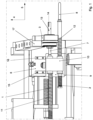
- Figure 1 a device for alternately inserting a first ram 1 or a second ram 2 into a ram loader 3 is shown.
- the first plunger 1 and the second plunger 2 are arranged on a holding plate 6 so as to be movable in a first direction of movement 4.
- the holding plate 6 has a first rail 15 and a second rail 16.
- a carriage 9 is movable on the rails 15, 16, wherein the carriage 9 has a receptacle 10.
- the first plunger 1 and the second plunger 2 are arranged parallel to each other on the carriage 9.
- the plungers 1, 2 are arranged in the receptacle 10.
- the first plunger 1 comprises a first breakout claw head 7.
- the second plunger 2 comprises a second breakout claw head 8.
- the first plunger 1 has a first spring 11.
- the second plunger 2 has a second spring 12.
- the receptacle 10 also serves as a stop for the springs 11, 12.
- the springs 12 and 13 are coil springs, each arranged around the two plungers.
- Spring 12 is arranged around plunger 1, while spring 13 is arranged around plunger 2.
- the holding plate 6 is arranged on a functional plate 17.
- the functional plate 17 in turn serves as a stop for the tappet loader 3.
- Figure 1 is shown how the tappet loader 3 has moved towards the function plate 17.
- Figure 2 it is shown how the tappet loader 3 has moved in the second direction of movement 5 away from the functional plate 17.
- the ram loader 3 can be moved in a second direction of movement 5, wherein the first direction of movement 4 is orthogonal to the second direction of movement 5.
- the ram loader 3 has a guide sleeve 13.
- the guide sleeve 13 has a stripping claw receiving slot 14.
- the stripping claw receiving slot 14 serves to automatically accommodate stripping claws. For this purpose, the ram loader 3 is moved in the second direction of movement 5. A stripping claw is inserted into the stripping claw receiving slot 14.
- the carriage 9 is moved along the rails 15, 16 in the first direction of movement 4.
- the carriage 9 comprises a drive (not shown in detail) that can be moved in the first direction of movement 4. Furthermore, the ram loader 3 can be moved in the second direction of movement 5 by a further drive (also not shown).
Landscapes
- Life Sciences & Earth Sciences (AREA)
- Forests & Forestry (AREA)
- Engineering & Computer Science (AREA)
- Mechanical Engineering (AREA)
- Supply And Installment Of Electrical Components (AREA)
- Automatic Tool Replacement In Machine Tools (AREA)
- Automatic Assembly (AREA)
- Coating Apparatus (AREA)
- Manufacturing Of Electrical Connectors (AREA)
Description
- Die Erfindung betrifft eine Vorrichtung zum wechselnden Einschub eines ersten Stössels oder eines zweiten Stössels nach dem Oberbegriff des Anspruchs 1.
- Aus dem Stand der Technik sind verschiedene Automatisierungstechniken für das Herstellen eines Ausbrechwerkzeugs bekannt und gebräuchlich.
- In diesem Zusammenhang wird auf die
US 5,049,122 hingewiesen welche eine Automatisierung für Ausbrechstifte offenbart. - Weiter wird auf die
DE 297077921 hingewiesen, welche ebenfalls ein automatisiertes Verfahren zur Herstellung eines Ausbrechwerkzeugs offenbart, wobei auch hier Ausbrechstifte automatisiert eingesetzt werden. - In gleicher Weise wird auf die
US 5,291,652 A und dieDE 4103339 A1 hingewiesen. - Die
DE 10 2008 062 114 A1 zeigt eine Vorrichtung nach dem Oberbegriff von Anspruch 1. - Keine der Entgegenhaltungen beschreibt allerdings ein automatisiertes Herstellungsverfahren eines Ausbrechwerkzeuges, wobei nicht nur Ausbrechstifte, sondern auch flächige Ausbrechkrallen eingesetzt werden sollen.
- Die Aufgabe der vorliegenden Erfindung ist es, die Nachteile aus dem Stand der Technik zu überwinden. Insbesondere soll eine Vorrichtung bereitgestellt werden, die ein automatisiertes Herstellen eines Ausbrechwerkzeuges ermöglicht, bei dem neben den Ausbrechstiften auch Ausbrechkrallen automatisch und maschinell gesetzt werden können. Dies soll in der Weise erfolgen, dass ausserdem unterschiedliche Stössel platzsparend mit ein und demselben Stössellader einfach und schnell gesetzt werden können.
- Zur Lösung der Aufgabe führen die Merkmale nach dem Anspruch 1. Vorteilhafte Ausgestaltungen sind in den Unteransprüchen beschrieben.
- Eine erfindungsgemässe Vorrichtung dient zum wechselnden Einschub eines ersten Stössels oder eines zweiten Stössels in einen Stössellader. Zwei unterschiedliche Stössel sind hier von Vorteil, da die beiden Stössel unterschiedliche Eigenschaften haben können, um beispielsweise unterschiedliche Ausbrechkrallen in das Ausbrechwerkzeug einzusetzen. Ein entsprechender schneller Wechsel zwischen dem ersten Stössel und dem zweiten Stössel ist daher wesentlich.
- Dabei sind der erste Stössel und der zweite Stössel in einer ersten Bewegungsrichtung verfahrbar an einer Halteplatte angeordnet. Der Stössellader ist in einer zweiten Bewegungsrichtung verfahrbar ist, wobei die erste Bewegungsrichtung zur zweiten Bewegungsrichtung orthogonal liegt. Die erste Bewegungsrichtung und die zweite Bewegungsrichtung sind ausserdem reversibel. Das bedeutet, dass jede Bewegungsrichtung auch nach den Erfordernissen des Nutzers umgekehrt werden kann.
- Der erste Stössel umfasst einen ersten Ausbrechkrallenkopf und der zweite Stössel umfasst einen zweiten Ausbrechkrallenkopf.
- Der erste Stössel weist eine erste Feder auf und der zweite Stössel weist eine zweite Feder auf. Die beiden Federn können beispielsweise der Rückstellung der beiden Stössel dienen.
- Der erste Stössel und der zweite Stössel sind auf einem Schlitten parallel zueinander angeordnet. Auf dem Schlitten ist eine Aufnahme angeordnet, wobei der erste Stössel und der zweite Stössel in der Aufnahme gehalten werden. Dabei wird der Schlitten über zwei Schienen verfahren, welche auf der Halteplatte angeordnet sind. Dabei weist der Schlitten beispielsweise Nuten auf, die mit den Schienen in Wirkverbindung stehen und ein definiertes Verfahren des Schlittens erlauben.
- Der Stössellader weist eine Führungshülse auf. Die Führungshülse dient dabei der Aufnahme, der Halterung und des Einbringens der Ausbrechkralle in ein Ausbrechwerkzeug. Dazu weist die Führungshülse einen Ausbrechkrallen-Aufnahmeschlitz auf.
- Weiter ist der Schlitten durch einen Antrieb in die erste Bewegungsrichtung mobiliserbar. Der Stössellader ist ebenfalls durch einen weiteren Antrieb in die zweite Bewegungsrichtung bewegbar ist. Nachdem der Stössellader durch Verfahren in die zweite Bewegungsrichtung den ersten Ausbrechkrallenkopf freigegeben hat, kann der Schlitten beispielsweise in der ersten Bewegungsrichtung verfahren werden bis der zweite Ausbrechkrallenkopf derart positioniert ist, dass bei einem Rückfahren des Stösselladers entgegen der zweiten Bewegungsrichtung der zweite Ausbrechkrallenkopf in den Stössellader einfährt, um eine eventuell in dem Ausbrechkrallen-Aufnahmeschlitz gehalterte Ausbrechkralle beispielsweise in ein Holzbrett zu treiben, um ein Ausbrechwerkzeug herzustellen. Dieser Vorgang zum automatisierten Setzen von Ausbrechkrallen kann beliebig oft wiederholt werden.
- Die erste Bewegungsrichtung und die zweite Bewegungsrichtung sind jeweils reversibel verfahrbar.
- Weitere Vorteile, Merkmale und Einzelheiten der Erfindung ergeben sich aus der nachfolgenden Beschreibung bevorzugter Ausführungsbeispiele sowie anhand der Zeichnungen; diese zeigen in:
- Figur 1
- eine erfindungsgemässe Vorrichtung in einer ersten Lage;
- Figur 2
- die erfindungsgemässe Vorrichtung nach
Figur 1 in einer zweiten Lage. - In
Figur 1 ist eine Vorrichtung zum wechselnden Einschub eines ersten Stössels 1 oder eines zweiten Stössels 2 in einen Stössellader 3 dargestellt. - Der erste Stössel 1 und der zweite Stössel 2 sind in einer ersten Bewegungsrichtung 4 verfahrbar an einer Halteplatte 6 angeordnet.
- Dazu weist die Halteplatte 6 eine erste Schiene 15 und eine zweite Schiene 16 auf. Auf den Schienen 15, 16 ist ein Schlitten 9 verfahrbar, wobei der Schlitten 9 eine Aufnahme 10 vorhanden.
- Der erste Stössel 1 und der zweite Stössel 2 sind parallel auf dem Schlitten 9 parallel zueinander angeordnet. Dabei sind die Stössel 1, 2 in der Aufnahme 10 angeordnet.
- Der erste Stössel 1 umfasst einen ersten Ausbrechkrallenkopf 7. Der zweite Stössel 2 umfasst einen zweiten Ausbrechkrallenkopf 8. Der erste Stössel 1 weist eine erste Feder 11 auf. Der zweite Stössel 2 weist eine zweite Feder 12 auf. Die Aufnahme 10 dient auch als Anschlag für die Federn 11, 12.
- Bei den Federn 12, 13 handelt es sich um Sprungfedern, welche jeweils um die beiden Stössel herum angeordnet sind. Dabei ist die Feder 12 um den Stössel 1 herum angeordnet. Die Feder 13 ist um den Stössel 2 herum angeordnet.
- Die Halteplatte 6 ist an einer Funktionsplatte 17 angeordnet. Die Funktionsplatte 17 wiederum dient als Anschlag für den Stössellader 3. In
Figur 1 ist gezeigt, wie der Stößellader 3 an die Funktionsplatte 17 herangefahren ist. InFigur 2 ist gezeigt, wie der Stössellader 3 in der zweiten Bewegungsrichtung 5 weg von der Funktionsplatte 17 verfahren ist. - Der Stössellader 3 ist in einer zweiten Bewegungsrichtung 5 verfahrbar, wobei die erste Bewegungsrichtung 4 zur zweiten Bewegungsrichtung 5 orthogonal liegt.
- Der Stössellader 3 weist eine Führungshülse 13 auf. Dabei weist die Führungshülse 13 einen Ausbrechkrallen-Aufnahmeschlitz 14 auf. Der Ausbrechkrallen-Aufnahmeschlitz 14 dient der automatisierten Aufnahme von Ausbrechkrallen. Dazu wird der Stössellader 3 in der zweiten Bewegungsrichtung 5 verfahren. Dabei wird eine Ausbrechkralle in den Ausbrechkrallen-Aufnahmeschlitz 14 eingeschoben.
- Nachdem der Stössellader 3 entgegen der zweiten Bewegungsrichtung 5 in Richtung der Funktionsplatte 17 rückverfahren wird, fährt der erste Ausbrechkrallenkopf 7 oder der zweite Ausbrechkrallenkopf 8 in der Führungshülse 13 positioniert. Soll der zweite Ausbrechkrallenkopf 8 zum Einsatz gebracht werden, wird der Schlitten 9 auf den Schienen 15, 16 in die erste Bewegungsrichtung 4 verfahren.
- Der Schlitten 9 umfasst einen nicht näher gezeigten Antrieb in die erste Bewegungsrichtung 4 verfahrbar ist. Weiter ist der Stössellader 3 durch einen ebenfalls nicht gezeigten weiteren Antrieb in die zweite Bewegungsrichtung 5 bewegbar ist.
-
1 Erster Stössel 34 2 Zweiter Stössel 35 3 Stössellader 36 4 Erste Bewegungsrichtung 37 5 Zweite Bewegungsrichtung 38 6 Halteplatte 39 7 Erster Ausbrechkrallenkopf 40 8 Zweiter Ausbrechkrallenkopf 41 9 Schlitten 42 10 Aufnahme 43 11 Erste Feder 44 12 Zweite Feder 45 13 Führungshülse 46 14 Ausbrechkrallen-Aufnahmeschlitz 47 15 Erste Schiene 48 16 Zweite Schiene 49 17 Funktionsplatte 50 18 51 19 52 20 53 21 54 22 55 23 56 24 57 25 58 26 59 27 60 28 61 29 62 30 63 31 64 32 65 33 66
Claims (8)
- Vorrichtung zum wechselnden Einschub eines ersten Stössels (1) oder eines zweiten Stössels (2) in einen Stössellader (3), wobei der erste Stössel (1) und der zweite Stössel (2) in einer ersten Bewegungsrichtung (4) verfahrbar an einer Halteplatte (6) angeordnet sind, wobei der Stössellader (3) in einer zweiten Bewegungsrichtung (5) verfahrbar ist, wobei die erste Bewegungsrichtung (4) zur zweiten Bewegungsrichtung (5) orthogonal liegt, dadurch gekennzeichnet, dass
der Stössellader (3) eine Führungshülse (13) aufweist, die einen Ausbrechkrallen-Aufnahmeschlitz (14) aufweist. - Vorrichtung nach Anspruch 1, dadurch gekennzeichnet, dass der erste Stössel (1) einen ersten Ausbrechkrallenkopf (7) umfasst und der zweite Stössel (2) einen zweiten Ausbrechkrallenkopf (8) umfasst.
- Vorrichtung nach Anspruch 1 oder 2, dadurch gekennzeichnet, dass der erste Stössel (1) eine erste Feder (11) aufweist und der zweite Stössel (2) eine zweite Feder (12) aufweist.
- Vorrichtung nach einem der vorigen Ansprüche, dadurch gekennzeichnet, dass der erste Stössel (1) und der zweite Stössel (2) auf einem Schlitten (9) parallel zueinander angeordnet sind.
- Vorrichtung nach Anspruch 4, dadurch gekennzeichnet, dass auf dem Schlitten (9) eine Aufnahme (10) angeordnet, wobei der erste Stössel (1) und der zweite Stössel (2) in der Aufnahme (10) gehalten werden.
- Vorrichtung nach Anspruch 5, dadurch gekennzeichnet, dass die Aufnahme (10) als Anschlag für die erste Feder (11) und die zweite Feder (12) dient.
- Vorrichtung nach einem der vorigen Ansprüche, dadurch gekennzeichnet, dass der Schlitten (9) durch einen Antrieb in die erste Bewegungsrichtung (4) ist.
- Vorrichtung nach einem der vorigen Ansprüche, dadurch gekennzeichnet, dass der Stössellader (3) durch einen weiteren Antrieb in die zweite Bewegungsrichtung (5) bewegbar ist.
Applications Claiming Priority (2)
| Application Number | Priority Date | Filing Date | Title |
|---|---|---|---|
| DE102017100957.4A DE102017100957A1 (de) | 2017-01-18 | 2017-01-18 | Vorrichtung zum wechselnden Einschub eines ersten Stössels oder eines zweiten Stössels |
| PCT/EP2018/050918 WO2018134163A1 (de) | 2017-01-18 | 2018-01-16 | Vorrichtung zum wechselnden einschub eines ersten stössels oder eines zweiten stössels |
Publications (3)
| Publication Number | Publication Date |
|---|---|
| EP3571029A1 EP3571029A1 (de) | 2019-11-27 |
| EP3571029B1 true EP3571029B1 (de) | 2025-06-04 |
| EP3571029C0 EP3571029C0 (de) | 2025-06-04 |
Family
ID=61003014
Family Applications (1)
| Application Number | Title | Priority Date | Filing Date |
|---|---|---|---|
| EP18700668.9A Active EP3571029B1 (de) | 2017-01-18 | 2018-01-16 | Vorrichtung zum wechselnden einschub eines ersten stössels oder eines zweiten stössels |
Country Status (6)
| Country | Link |
|---|---|
| US (1) | US11618179B2 (de) |
| EP (1) | EP3571029B1 (de) |
| CN (1) | CN110191787B (de) |
| DE (1) | DE102017100957A1 (de) |
| ES (1) | ES3032316T3 (de) |
| WO (1) | WO2018134163A1 (de) |
Citations (2)
| Publication number | Priority date | Publication date | Assignee | Title |
|---|---|---|---|---|
| US5291652A (en) * | 1987-10-13 | 1994-03-08 | Meurer Nonfood Product Gmbh | Apparatus for the production of a device for detaching portions of plate-like workpieces |
| DE102008062114A1 (de) * | 2008-12-16 | 2010-06-17 | Joachim Jakob | Vorrichtung zum Einsetzen eines Ausbrechstiftes in ein Ausbrechwerkzeug |
Family Cites Families (30)
| Publication number | Priority date | Publication date | Assignee | Title |
|---|---|---|---|---|
| US4139941A (en) * | 1977-09-22 | 1979-02-20 | Clopay Corporation | Window shade cutter |
| FR2610375A1 (fr) * | 1987-01-30 | 1988-08-05 | Prospection & Inventions | Tampon de fixation de panneau |
| US5049122A (en) | 1989-09-19 | 1991-09-17 | Marguip, Inc. | Apparatus for stripping scrap from die cut blanks |
| DE4103339A1 (de) | 1991-02-05 | 1992-09-03 | Naumann Spezialwerkzeug Gmbh | Ausbrechwerkzeug |
| JP3290292B2 (ja) * | 1994-03-29 | 2002-06-10 | 株式会社ニフコ | 留め具 |
| DE29603683U1 (de) * | 1996-02-29 | 1996-08-01 | Meurer Nonfood Product GmbH, 78315 Radolfzell | Vorrichtung zum Bearbeiten von Kartonbogen o.dgl. Flächenstücken |
| DE19617688A1 (de) | 1996-05-03 | 1997-11-13 | Juergen Kara | Verfahren und Ausbrechwerkzeug zum Ausbrechen von Stanzabfällen bei der Herstellung von Zuschnitten aus einem Bogen |
| US5844142A (en) * | 1997-04-30 | 1998-12-01 | Ethicon, Inc. | Pull test apparatus for permanently attached sutures |
| DE29707921U1 (de) | 1997-05-02 | 1997-07-10 | CD Cartondruck GmbH, 74182 Obersulm | Verpackungsvorrichtung für Waren |
| DE10023896A1 (de) * | 2000-05-17 | 2001-11-22 | Meurer Stanztechnologie Gmbh | Vorrichtung und Verfahren zum Einsetzen eines Ausbrechstiftes |
| US6557878B2 (en) * | 2001-02-22 | 2003-05-06 | Giant Manufacturing Co., Ltd. | Locking device for releasably locking a seat post relative to a seat tube of a bicycle frame |
| US7922213B2 (en) * | 2003-10-17 | 2011-04-12 | Twin Bay Medical, Inc. | Barb clamp with smooth bore |
| US7484919B2 (en) * | 2006-01-24 | 2009-02-03 | Illinois Tool Works Inc. | Fastener assembly |
| US20080226420A1 (en) * | 2007-03-12 | 2008-09-18 | Joker Industrial Co., Ltd. | Adjusting screw for door frames and window casings |
| DE202007017069U1 (de) * | 2007-06-26 | 2008-05-29 | Heidelberger Druckmaschinen Ag | Werkzeug für Bogenstanz- und -prägemaschine |
| DE202008012789U1 (de) * | 2008-09-25 | 2010-03-04 | Silcoplan Engineering Gmbh | Vorrichtung zum Einsetzen von Ausbrechstiften |
| CN201346593Y (zh) * | 2008-12-09 | 2009-11-18 | 天津市天锻压力机有限公司 | 一种瓦棱板压制冲孔液压模具 |
| US9321095B2 (en) * | 2010-06-30 | 2016-04-26 | General Electric Company | Apparatuses and methods for cutting porous substrates |
| US8961063B2 (en) * | 2010-12-02 | 2015-02-24 | Coupling Corporation Of America, Inc. | Hub clamp assembly |
| CN202070894U (zh) * | 2011-04-12 | 2011-12-14 | 重庆宗申发动机制造有限公司 | 一种锁夹压机 |
| DE102012103858B4 (de) | 2011-12-05 | 2024-01-25 | Boxplan Gmbh | Vorrichtung und Verfahren zum Herstellen eines Ausbrechwerkzeuges |
| JP5788829B2 (ja) * | 2012-04-06 | 2015-10-07 | 株式会社山田製作所 | ステアリング装置 |
| CN103372613B (zh) | 2012-04-18 | 2015-09-23 | 珠海格力电器股份有限公司 | 冲铆装置 |
| NO337229B1 (no) * | 2012-07-12 | 2016-02-15 | Ace Oil Tools As | Festeanordning for ei rørstamme forsynt med ett eller flere aksielt utragende funksjonselement innrettet til anvendelse på et nedihulls rørlegeme, samt rørstreng omfattende flere rørlegemer |
| CN102862047B (zh) * | 2012-09-25 | 2015-08-05 | 浙江华奔机械制造有限公司 | 一种拆销钉机结构 |
| CN203124577U (zh) * | 2012-12-24 | 2013-08-14 | 宁波德诚工具有限公司 | 一种自动冲压磁缸装置 |
| CN105881437A (zh) * | 2014-11-25 | 2016-08-24 | 常州市沁惠机械厂 | 全自动螺丝刀架 |
| CN205703184U (zh) * | 2016-04-21 | 2016-11-23 | 深圳创维-Rgb电子有限公司 | 一种交替式高效打螺钉装置 |
| DE102016108880A1 (de) * | 2016-05-13 | 2017-11-16 | Joachim Jakob | Hybridsetter |
| US10189151B2 (en) * | 2016-11-14 | 2019-01-29 | Snap-On Incorporated | Compact head body hammer |
-
2017
- 2017-01-18 DE DE102017100957.4A patent/DE102017100957A1/de active Pending
-
2018
- 2018-01-16 ES ES18700668T patent/ES3032316T3/es active Active
- 2018-01-16 CN CN201880007241.5A patent/CN110191787B/zh active Active
- 2018-01-16 WO PCT/EP2018/050918 patent/WO2018134163A1/de not_active Ceased
- 2018-01-16 US US16/475,346 patent/US11618179B2/en active Active
- 2018-01-16 EP EP18700668.9A patent/EP3571029B1/de active Active
Patent Citations (2)
| Publication number | Priority date | Publication date | Assignee | Title |
|---|---|---|---|---|
| US5291652A (en) * | 1987-10-13 | 1994-03-08 | Meurer Nonfood Product Gmbh | Apparatus for the production of a device for detaching portions of plate-like workpieces |
| DE102008062114A1 (de) * | 2008-12-16 | 2010-06-17 | Joachim Jakob | Vorrichtung zum Einsetzen eines Ausbrechstiftes in ein Ausbrechwerkzeug |
Also Published As
| Publication number | Publication date |
|---|---|
| EP3571029A1 (de) | 2019-11-27 |
| CN110191787B (zh) | 2021-11-30 |
| ES3032316T3 (en) | 2025-07-17 |
| CN110191787A (zh) | 2019-08-30 |
| US20190337182A1 (en) | 2019-11-07 |
| WO2018134163A1 (de) | 2018-07-26 |
| US11618179B2 (en) | 2023-04-04 |
| EP3571029C0 (de) | 2025-06-04 |
| DE102017100957A1 (de) | 2018-07-19 |
Similar Documents
| Publication | Publication Date | Title |
|---|---|---|
| DE102015212541A1 (de) | Bearbeitungsvorrichtung | |
| DE102015218814A1 (de) | Bearbeitungsvorrichtung | |
| EP3370892B1 (de) | Greifersystem für eine biegepresse | |
| DE202009004913U1 (de) | Vorrichtung zum Verdrillen von Leitungen | |
| EP3240123B1 (de) | Crimpwerkzeug-austauschvorrichtung und verfahren zum austauschen eines an einer prozessposition in einer crimppresse angeordneten ersten crimpwerkzeuges gegen ein anderes zweites crimpwerkzeug | |
| DE202008012789U1 (de) | Vorrichtung zum Einsetzen von Ausbrechstiften | |
| DE1955193A1 (de) | Verfahren und Vorrichtung zum Werkzeugwechsel an einer Maschine mit hin- und hergehender Arbeitsbewegung | |
| EP3793816B1 (de) | Keiltrieb mit justierbarer führungsvorrichtung | |
| DE102015110115A1 (de) | Vorrichtung zum Bearbeiten eines Werkstücks | |
| DE29716104U1 (de) | Spannvorrichtung, insbesondere Maschinenschraubstock | |
| DE102014222423A1 (de) | Spannvorrichtung | |
| DE19824741C2 (de) | Verfahren und Vorrichtung zur Herstellung von Bundlagern | |
| DE202016103652U1 (de) | Werkstückklemmvorrichtung mit veränderbarem Klemmwinkel | |
| EP3242131B1 (de) | Einspannvorrichtung für eine probenvorbereitung | |
| EP3571029B1 (de) | Vorrichtung zum wechselnden einschub eines ersten stössels oder eines zweiten stössels | |
| DE102016203286A1 (de) | Verfahren zur Montage einer Stiftleiste mit mehreren Stiften an einer Leiterplatte, Leiterplatte mit einer Stiftleiste mit mehreren Stiften und Vorrichtung zur Montage einer Stiftleiste mit mehreren Stiften auf einer Leiterplatte | |
| EP3065223A1 (de) | Reihenklemme | |
| DE102018001438A1 (de) | Vorrichtung zur Bearbeitung mindestens eines Werkstücks | |
| DE102018126018A1 (de) | Werkstückabstützung zur Abstützung von Rohrmaterial in einer Rohrbearbeitungsmaschine und Rohrbearbeitungsmaschine | |
| EP3511131A1 (de) | Vorrichtung und verfahren zum handhaben von brillengläsern sowie verfahren zur herstellung von brillengläsern | |
| EP3372320A1 (de) | Vorrichtung und verfahren zur herstellung mäanderförmiger kühlkörper | |
| EP2487009B1 (de) | Spannvorrichtung für eine Werkzeugmaschine | |
| DE102009052747A1 (de) | Positioniervorrichtung für ein Spannsystem | |
| DE102018125869A1 (de) | Vorrichtung zum Abstützen wenigstens eines Bauteils | |
| BE1025998B1 (de) | Werkstückspannvorrichtung und Bürstenherstellungsmaschine |
Legal Events
| Date | Code | Title | Description |
|---|---|---|---|
| STAA | Information on the status of an ep patent application or granted ep patent |
Free format text: STATUS: UNKNOWN |
|
| STAA | Information on the status of an ep patent application or granted ep patent |
Free format text: STATUS: THE INTERNATIONAL PUBLICATION HAS BEEN MADE |
|
| PUAI | Public reference made under article 153(3) epc to a published international application that has entered the european phase |
Free format text: ORIGINAL CODE: 0009012 |
|
| STAA | Information on the status of an ep patent application or granted ep patent |
Free format text: STATUS: REQUEST FOR EXAMINATION WAS MADE |
|
| 17P | Request for examination filed |
Effective date: 20190812 |
|
| AK | Designated contracting states |
Kind code of ref document: A1 Designated state(s): AL AT BE BG CH CY CZ DE DK EE ES FI FR GB GR HR HU IE IS IT LI LT LU LV MC MK MT NL NO PL PT RO RS SE SI SK SM TR |
|
| AX | Request for extension of the european patent |
Extension state: BA ME |
|
| DAV | Request for validation of the european patent (deleted) | ||
| DAX | Request for extension of the european patent (deleted) | ||
| STAA | Information on the status of an ep patent application or granted ep patent |
Free format text: STATUS: EXAMINATION IS IN PROGRESS |
|
| 17Q | First examination report despatched |
Effective date: 20200907 |
|
| RAP3 | Party data changed (applicant data changed or rights of an application transferred) |
Owner name: BOXPLAN GMBH |
|
| GRAP | Despatch of communication of intention to grant a patent |
Free format text: ORIGINAL CODE: EPIDOSNIGR1 |
|
| STAA | Information on the status of an ep patent application or granted ep patent |
Free format text: STATUS: GRANT OF PATENT IS INTENDED |
|
| GRAS | Grant fee paid |
Free format text: ORIGINAL CODE: EPIDOSNIGR3 |
|
| INTG | Intention to grant announced |
Effective date: 20250326 |
|
| GRAA | (expected) grant |
Free format text: ORIGINAL CODE: 0009210 |
|
| STAA | Information on the status of an ep patent application or granted ep patent |
Free format text: STATUS: THE PATENT HAS BEEN GRANTED |
|
| AK | Designated contracting states |
Kind code of ref document: B1 Designated state(s): AL AT BE BG CH CY CZ DE DK EE ES FI FR GB GR HR HU IE IS IT LI LT LU LV MC MK MT NL NO PL PT RO RS SE SI SK SM TR |
|
| REG | Reference to a national code |
Ref country code: GB Ref legal event code: FG4D Free format text: NOT ENGLISH |
|
| REG | Reference to a national code |
Ref country code: CH Ref legal event code: EP |
|
| REG | Reference to a national code |
Ref country code: DE Ref legal event code: R096 Ref document number: 502018015852 Country of ref document: DE |
|
| REG | Reference to a national code |
Ref country code: IE Ref legal event code: FG4D Free format text: LANGUAGE OF EP DOCUMENT: GERMAN |
|
| REG | Reference to a national code |
Ref country code: ES Ref legal event code: FG2A Ref document number: 3032316 Country of ref document: ES Kind code of ref document: T3 Effective date: 20250717 |
|
| U01 | Request for unitary effect filed |
Effective date: 20250620 |
|
| U07 | Unitary effect registered |
Designated state(s): AT BE BG DE DK EE FI FR IT LT LU LV MT NL PT RO SE SI Effective date: 20250701 |
|
| PG25 | Lapsed in a contracting state [announced via postgrant information from national office to epo] |
Ref country code: NO Free format text: LAPSE BECAUSE OF FAILURE TO SUBMIT A TRANSLATION OF THE DESCRIPTION OR TO PAY THE FEE WITHIN THE PRESCRIBED TIME-LIMIT Effective date: 20250904 Ref country code: GR Free format text: LAPSE BECAUSE OF FAILURE TO SUBMIT A TRANSLATION OF THE DESCRIPTION OR TO PAY THE FEE WITHIN THE PRESCRIBED TIME-LIMIT Effective date: 20250905 |
|
| PG25 | Lapsed in a contracting state [announced via postgrant information from national office to epo] |
Ref country code: PL Free format text: LAPSE BECAUSE OF FAILURE TO SUBMIT A TRANSLATION OF THE DESCRIPTION OR TO PAY THE FEE WITHIN THE PRESCRIBED TIME-LIMIT Effective date: 20250604 |
|
| PG25 | Lapsed in a contracting state [announced via postgrant information from national office to epo] |
Ref country code: HR Free format text: LAPSE BECAUSE OF FAILURE TO SUBMIT A TRANSLATION OF THE DESCRIPTION OR TO PAY THE FEE WITHIN THE PRESCRIBED TIME-LIMIT Effective date: 20250604 |
|
| PG25 | Lapsed in a contracting state [announced via postgrant information from national office to epo] |
Ref country code: RS Free format text: LAPSE BECAUSE OF FAILURE TO SUBMIT A TRANSLATION OF THE DESCRIPTION OR TO PAY THE FEE WITHIN THE PRESCRIBED TIME-LIMIT Effective date: 20250904 |
|
| PG25 | Lapsed in a contracting state [announced via postgrant information from national office to epo] |
Ref country code: IS Free format text: LAPSE BECAUSE OF FAILURE TO SUBMIT A TRANSLATION OF THE DESCRIPTION OR TO PAY THE FEE WITHIN THE PRESCRIBED TIME-LIMIT Effective date: 20251004 |
|
| PG25 | Lapsed in a contracting state [announced via postgrant information from national office to epo] |
Ref country code: SM Free format text: LAPSE BECAUSE OF FAILURE TO SUBMIT A TRANSLATION OF THE DESCRIPTION OR TO PAY THE FEE WITHIN THE PRESCRIBED TIME-LIMIT Effective date: 20250604 |
|
| PG25 | Lapsed in a contracting state [announced via postgrant information from national office to epo] |
Ref country code: SK Free format text: LAPSE BECAUSE OF FAILURE TO SUBMIT A TRANSLATION OF THE DESCRIPTION OR TO PAY THE FEE WITHIN THE PRESCRIBED TIME-LIMIT Effective date: 20250604 |
|
| REG | Reference to a national code |
Ref country code: CH Ref legal event code: U11 Free format text: ST27 STATUS EVENT CODE: U-0-0-U10-U11 (AS PROVIDED BY THE NATIONAL OFFICE) Effective date: 20260201 |
|
| U20 | Renewal fee for the european patent with unitary effect paid |
Year of fee payment: 9 Effective date: 20260129 |
|
| PGFP | Annual fee paid to national office [announced via postgrant information from national office to epo] |
Ref country code: ES Payment date: 20260227 Year of fee payment: 9 |
|
| PLBE | No opposition filed within time limit |
Free format text: ORIGINAL CODE: 0009261 |
|
| STAA | Information on the status of an ep patent application or granted ep patent |
Free format text: STATUS: NO OPPOSITION FILED WITHIN TIME LIMIT |
|
| REG | Reference to a national code |
Ref country code: CH Ref legal event code: L10 Free format text: ST27 STATUS EVENT CODE: U-0-0-L10-L00 (AS PROVIDED BY THE NATIONAL OFFICE) Effective date: 20260416 |
|
| PGFP | Annual fee paid to national office [announced via postgrant information from national office to epo] |
Ref country code: TR Payment date: 20260115 Year of fee payment: 9 |
|
| PGFP | Annual fee paid to national office [announced via postgrant information from national office to epo] |
Ref country code: CH Payment date: 20260201 Year of fee payment: 9 Ref country code: CZ Payment date: 20260114 Year of fee payment: 9 |
|
| U1N | Appointed representative for the unitary patent procedure changed after the registration of the unitary effect |
Representative=s name: MARKS & CLERK LLP; GB |