EP3571033B1 - Procédé de la fabrication d'une - Google Patents
Procédé de la fabrication d'une Download PDFInfo
- Publication number
- EP3571033B1 EP3571033B1 EP17701995.7A EP17701995A EP3571033B1 EP 3571033 B1 EP3571033 B1 EP 3571033B1 EP 17701995 A EP17701995 A EP 17701995A EP 3571033 B1 EP3571033 B1 EP 3571033B1
- Authority
- EP
- European Patent Office
- Prior art keywords
- emc
- plastic
- electronics
- shielding housing
- potting compound
- Prior art date
- Legal status (The legal status is an assumption and is not a legal conclusion. Google has not performed a legal analysis and makes no representation as to the accuracy of the status listed.)
- Not-in-force
Links
Images

Classifications
-
- B—PERFORMING OPERATIONS; TRANSPORTING
- B29—WORKING OF PLASTICS; WORKING OF SUBSTANCES IN A PLASTIC STATE IN GENERAL
- B29C—SHAPING OR JOINING OF PLASTICS; SHAPING OF MATERIAL IN A PLASTIC STATE, NOT OTHERWISE PROVIDED FOR; AFTER-TREATMENT OF THE SHAPED PRODUCTS, e.g. REPAIRING
- B29C45/00—Injection moulding, i.e. forcing the required volume of moulding material through a nozzle into a closed mould; Apparatus therefor
- B29C45/14—Injection moulding, i.e. forcing the required volume of moulding material through a nozzle into a closed mould; Apparatus therefor incorporating preformed parts or layers, e.g. injection moulding around inserts or for coating articles
- B29C45/14639—Injection moulding, i.e. forcing the required volume of moulding material through a nozzle into a closed mould; Apparatus therefor incorporating preformed parts or layers, e.g. injection moulding around inserts or for coating articles for obtaining an insulating effect, e.g. for electrical components
-
- B—PERFORMING OPERATIONS; TRANSPORTING
- B29—WORKING OF PLASTICS; WORKING OF SUBSTANCES IN A PLASTIC STATE IN GENERAL
- B29C—SHAPING OR JOINING OF PLASTICS; SHAPING OF MATERIAL IN A PLASTIC STATE, NOT OTHERWISE PROVIDED FOR; AFTER-TREATMENT OF THE SHAPED PRODUCTS, e.g. REPAIRING
- B29C45/00—Injection moulding, i.e. forcing the required volume of moulding material through a nozzle into a closed mould; Apparatus therefor
- B29C45/0013—Injection moulding, i.e. forcing the required volume of moulding material through a nozzle into a closed mould; Apparatus therefor using fillers dispersed in the moulding material, e.g. metal particles
-
- B—PERFORMING OPERATIONS; TRANSPORTING
- B29—WORKING OF PLASTICS; WORKING OF SUBSTANCES IN A PLASTIC STATE IN GENERAL
- B29C—SHAPING OR JOINING OF PLASTICS; SHAPING OF MATERIAL IN A PLASTIC STATE, NOT OTHERWISE PROVIDED FOR; AFTER-TREATMENT OF THE SHAPED PRODUCTS, e.g. REPAIRING
- B29C45/00—Injection moulding, i.e. forcing the required volume of moulding material through a nozzle into a closed mould; Apparatus therefor
- B29C45/14—Injection moulding, i.e. forcing the required volume of moulding material through a nozzle into a closed mould; Apparatus therefor incorporating preformed parts or layers, e.g. injection moulding around inserts or for coating articles
- B29C45/14819—Injection moulding, i.e. forcing the required volume of moulding material through a nozzle into a closed mould; Apparatus therefor incorporating preformed parts or layers, e.g. injection moulding around inserts or for coating articles the inserts being completely encapsulated
-
- H—ELECTRICITY
- H05—ELECTRIC TECHNIQUES NOT OTHERWISE PROVIDED FOR
- H05K—PRINTED CIRCUITS; CASINGS OR CONSTRUCTIONAL DETAILS OF ELECTRIC APPARATUS; MANUFACTURE OF ASSEMBLAGES OF ELECTRICAL COMPONENTS
- H05K9/00—Screening of apparatus or components against electric or magnetic fields
- H05K9/0007—Casings
- H05K9/0047—Casings being rigid plastic containers having conductive particles, fibres or mesh embedded therein
-
- H—ELECTRICITY
- H05—ELECTRIC TECHNIQUES NOT OTHERWISE PROVIDED FOR
- H05K—PRINTED CIRCUITS; CASINGS OR CONSTRUCTIONAL DETAILS OF ELECTRIC APPARATUS; MANUFACTURE OF ASSEMBLAGES OF ELECTRICAL COMPONENTS
- H05K9/00—Screening of apparatus or components against electric or magnetic fields
- H05K9/0073—Shielding materials
- H05K9/0081—Electromagnetic shielding materials, e.g. EMI, RFI shielding
- H05K9/009—Electromagnetic shielding materials, e.g. EMI, RFI shielding comprising electro-conductive fibres, e.g. metal fibres, carbon fibres, metallised textile fibres, electro-conductive mesh, woven, non-woven mat, fleece, cross-linked
Definitions
- the present invention relates to a method for producing an EMC shielding housing for electronics.
- EMC shielding housings are used to ensure the electromagnetic compatibility (EMC) of electronic devices, i.e. to reduce the electromagnetic radiation of electronic devices and to protect electronic devices against electromagnetic radiation.
- the electronic devices that require such EMC shielding include, for example, electric motors, drive elements, control devices, etc., for example in electronic household devices.
- plastic housings are often preferred, particularly for reasons of weight and price.
- EMC-effective plastic housing it is known, for example, to provide the plastic housing with an EMC-effective coating (metallic vapor deposition, conductive lacquer, etc.) or to use electrically conductive plastics for the housing.
- thermoplastic semifinished product for shielding against electromagnetic radiation can have a reinforcement material made of reinforcement fibers or reinforcement textile and conductive fibers, fiber sections or reinforcement textile which are impregnated with a thermoplastic matrix (e.g.
- the DE 10 2014 202 393 A1 describes an electrical circuit module with an electrical assembly which is embedded in an electrically non-conductive plastic molded body in which a molded body carrier made of metal is located for electrical shielding.
- the DE 195 28 731 A1 discloses a method for protecting electrical components in which the components are encased using an injection molding process with a potting compound made of thermoplastic material, in which conductive particles can also be provided for EMC shielding.
- the invention is based on the object of creating a simple manufacturing process for producing an EMC shielding housing made of plastic for electronics.
- the method according to the invention for producing an EMC shielding housing includes the steps of placing the electronics in a mold; inserting an EMC-effective fabric in the form of a prepreg 22, ie a fabric impregnated with a plastic material, into the mold in such a way that the EMC-effective fabric encloses the electronics at a distance therefrom; injecting a plastic component to form a potting compound for encapsulating the electronics in the mold, the plastic component for the potting compound at least partially penetrating the EMC-effective fabric; the injection of a first plastic component for Forming a plastic molded part of the EMC shielding housing adjacent to the EMC-effective fabric and the plastic component for the potting compound in the mold; and injecting a second plastic component for the plastic molded part of the EMC shielding housing into the mold adjoining the first plastic component for the plastic molded part of the EMC shielding housing.
- a plastic housing can be produced in a simple manner, which has EMC-shielding properties.
- the integration of the EMC-effective fabric during the molding process means that no additional process steps are required to subsequently provide a plastic housing with EMC shielding properties.
- the use of an EMC shielding fabric also does not restrict the design options for the shielding housing.
- the electronics can be integrated into the EMC shielding housing in a single production step with several sequential or parallel injection molding processes in a mold.
- the shielding housing can be a housing which completely or partially surrounds one or more electronic components.
- the housing can be closed or have one or more housing openings.
- the shielding housing can have various other special properties, such as, for example, thermal conductivity, at least partial transparency, and the like.
- the molding tool is basically any desired molding tool that is suitable for an injection molding process.
- the molding tool can in particular have one or more cavities, have one or more injection nozzles, be provided with one or more movable parts, and the like.
- the plastic components are basically any plastic material that is suitable for processing in an injection molding process.
- the first and second plastic components for the plastic molded part can consist of the same plastic material or of different plastic materials.
- the plastic component for the potting compound is preferably electrically non-conductive.
- the plastic component for the potting compound and the first plastic component for the molded part preferably each have a thermally conductive plastic material.
- the EMC-effective tissue is basically any tissue that can shield electromagnetic radiation.
- the shielding effect can in particular be achieved through the material properties and the configuration of the fabric.
- the fabric can preferably be formed from metal, plastic and / or textile threads.
- the term “fabric” is intended to encompass all types of woven, knitted, crocheted, braided, non-woven fabrics. Fabrics are easy to process and shape. The porosity of the tissue allows easy penetration with the plastic material and thus good integration.
- the EMC-effective fabric is placed in the mold in the form of a prepreg.
- a prepreg is an elastic piece of fabric that is saturated with a liquid plastic material so that it can be shaped and then stabilized by curing the plastic material (preferably by means of temperature and / or pressure).
- the plastic material is preferably a thermoset.
- the second plastic component for the plastic molded part of the EMC shielding housing has a thermoplastic.
- This variant is particularly advantageous when using a prepreg, since the plastic material in the prepreg is made up of the thermoplastic sufficient temperature and pressure is applied to allow it to harden. A subsequent separate curing step can thus be omitted.
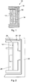
- FIG 1 shows the basic structure of an EMC shielding housing 10 according to an embodiment of the invention.
- the EMC shielding housing 10 is used for EMC-effective shielding of electronics 12 which are at least partially enclosed by the EMC shielding housing 10.
- the electronics 12 have, for example, a circuit board with electronic components of an electronic device such as an electric motor, drive element, control device, etc.
- the electronics 12 with the EMC shielding housing can be used, for example, in electronic household appliances such as laundry treatment appliances, hobs, stoves, microwave ovens, dishwashers, and the like.
- the EMC shielding housing 10 has a plastic molded part 14 made of one or more plastic components, which has been molded by an injection molding process.
- An EMC-effective fabric 16 is integrated in this plastic molded part 14. The integration takes place, for example, by at least partially encapsulating the fabric 16 with at least one plastic component of the plastic molded part, as described below.
- the electronics 12 are encapsulated in a potting compound 18.
- the potting compound 18 is preferably formed from a plastic component and is preferably thermally conductive. In addition to heat dissipation and mechanical protection of the electronics 12, the potting compound 18 can also serve to electrically insulate the electronics 12.
- the electronics 12 with the potting compound 18 are integrated with the plastic molded part 14 by means of a common injection molding process.
- the EMC shielding effect is integrated into the plastic molded part 14 of the EMC shielding housing 10 by means of composite injection molding or inline in the injection molding process.
- the electronics 12 are integrated into the EMC shielding housing 10 in a single production step with a plurality of sequential or parallel injection molding processes in a molding tool 20.
- the electronics 12 are placed in the molding tool 20.
- a plastic component 28 is then injected to form the potting compound 18.
- the EMC-effective fabric 16 in the form of a prepreg 22, ie a fabric (for example made of metal, plastic and / or textile threads) impregnated with a plastic material (eg a thermosetting plastic) is placed in the molding tool.
- a first plastic component 24 for forming the plastic molded part 14 is then first injected adjacent to the plastic component 28 for the potting compound 18.
- the first plastic component 24 preferably comprises a thermally conductive plastic material.
- the plastic components 24 and 28 merge with one another in their transition area.
- the prepreg 22 of the EMC-effective fabric 16 is back-injected with a second plastic component 26 for the plastic molded part 14.
- the second plastic component 26 is injected between the first plastic component 24 for the molded part 14 and the prepreg 22 and in the process also penetrates the prepreg 22.
- the plastic components 24 and 26 fuse with one another.
- the second plastic component 26 preferably has an elastomer whose temperature and pressure effect when the molded part 14 hardens also hardens the plastic material in the prepreg 22 and a subsequent hardening process can be dispensed with.
- the EMC-effective fabric 16 is ultimately located in the outer region of the plastic molded part 14 of the EMC shielding housing 10.
- the electronics 12 are also integrated into the EMC shielding housing 10 in a single production step with a plurality of sequential or parallel injection molding processes in a mold 20.
- the prepreg 22 encloses the electronics 12 at a certain distance from it.
- a plastic component 28 is then injected to form the potting compound 18.
- This plastic component 28 is preferably electrically non-conductive, so that it isolates the electronics 12 from the EMC-effective tissue 16.
- the plastic component 28 for the potting compound 18 penetrates the prepreg 22 at least partially.
- a first plastic component 24 for forming the plastic molded part 14 is first injected into the mold 20 adjacent to the prepreg 22 and the plastic component 28 for the potting compound 18.
- the plastic component 28 for the potting compound 18 and the first plastic component 24 for the molded part 14 each preferably have a thermally conductive plastic material.
- a second plastic component 26 for the molded part 14 is then injected adjacent to the first plastic component 24 for the molded part 14.
- the second plastic component 26 preferably has an elastomer whose temperature and pressure effect when the molded part 14 hardens also hardens the plastic material in the prepreg 22 and a subsequent hardening process can be dispensed with.
- the EMC-effective fabric 16 is ultimately located between the potting compound 18 encapsulating the electronics 12 and the plastic molded part 14 of the EMC shielding housing 10, the potting compound 18 and the molded part 14 being integrated with one another by the injection molding process.
- the plastic molded part 14 is formed from two plastic components 24, 26.
- the molded part 14 can also be formed from more than two plastic components.
- the second plastic component 26 for the molded part 14 is made of an elastomer whose temperature and pressure also cause the plastic material in the prepreg 22 to harden. If other plastic materials are used for the second plastic component 26, the plastic material in the prepreg 22 may have to be cured in a separate curing process.
- the EMC shielding housing 10 encloses the electronics 12 in the variant of FIG Fig. 3 only partially.
- the molded part 14 of the EMC shielding housing 10 can also completely enclose the electronics 12. Electrical connections of the electronics are then passed through the plastic components 24-26 of the EMC shielding housing 10, for example.
Landscapes
- Engineering & Computer Science (AREA)
- Manufacturing & Machinery (AREA)
- Mechanical Engineering (AREA)
- Microelectronics & Electronic Packaging (AREA)
- Textile Engineering (AREA)
- Physics & Mathematics (AREA)
- Electromagnetism (AREA)
- Chemical & Material Sciences (AREA)
- Dispersion Chemistry (AREA)
- Shielding Devices Or Components To Electric Or Magnetic Fields (AREA)
- Injection Moulding Of Plastics Or The Like (AREA)
Claims (4)
- Procédé de fabrication d'un boîtier de blindage CEM (10) destiné à une électronique (12), le procédé comprenant les étapes suivantes :placer l'électronique (12) dans un outil de moulage (20) ;insérer un tissu CEM-efficace (16) se présentant sous la forme d'un préimprégné (22), c'est-à-dire un tissu imprégné d'une matière synthétique, dans l'outil de moulage (20) de telle manière que le tissu CEM-efficace (16) enferme l'électronique (12) à distance de celle-ci ;injecter un composant de matière synthétique (28) pour former un composé d'enrobage (18) destiné à encapsuler l'électronique (12) dans l'outil de moulage (20), le composant de matière synthétique (28) destiné au composé d'enrobage (18) pénétrant au moins partiellement dans le tissu CEM-efficace (16) ;injecter un premier composant de matière synthétique (24), destiné à former une partie moulée (14) en matière synthétique du boîtier de CEM-blindage (10) de manière adjacente au tissu CEM-efficace (16), et le composant de matière synthétique (28) destiné au composé d'enrobage (18) dans l'outil de moulage (20) ; etinjecter un deuxième composant de matière synthétique (26) destiné à la partie moulée (14) en matière synthétique du boîtier de CEM-blindage (10) dans l'outil de moulage (20) de manière adjacente au premier composant de matière synthétique (24) destiné à la partie moulée (14) en matière synthétique du boîtier de CEM-blindage (10).
- Procédé selon la revendication 1, dans lequel
le composant de matière synthétique (28) destiné au composé d'enrobage (18) est électriquement non conducteur. - Procédé selon l'une des revendications précédentes, dans lequel
le composant de matière synthétique (28) destiné au composé d'enrobage (18) et le premier composant de matière synthétique (24) destiné à la pièce moulée (14) comportent chacun une matière synthétique thermoconductrice. - Procédé selon l'une des revendications précédentes, dans lequel
le deuxième composant de matière synthétique (26) destiné à la partie moulée (14) en matière synthétique du boîtier de CEM-blindage (10) comprend une matière thermoplastique.
Applications Claiming Priority (1)
| Application Number | Priority Date | Filing Date | Title |
|---|---|---|---|
| PCT/EP2017/000060 WO2018133911A1 (fr) | 2017-01-19 | 2017-01-19 | Procédé de fabrication d'un boîtier de blindage cem et boîtier de blindage cem |
Publications (2)
| Publication Number | Publication Date |
|---|---|
| EP3571033A1 EP3571033A1 (fr) | 2019-11-27 |
| EP3571033B1 true EP3571033B1 (fr) | 2020-12-23 |
Family
ID=57914929
Family Applications (1)
| Application Number | Title | Priority Date | Filing Date |
|---|---|---|---|
| EP17701995.7A Not-in-force EP3571033B1 (fr) | 2017-01-19 | 2017-01-19 | Procédé de la fabrication d'une |
Country Status (4)
| Country | Link |
|---|---|
| US (1) | US20190329467A1 (fr) |
| EP (1) | EP3571033B1 (fr) |
| CN (1) | CN110198824B (fr) |
| WO (1) | WO2018133911A1 (fr) |
Family Cites Families (11)
| Publication number | Priority date | Publication date | Assignee | Title |
|---|---|---|---|---|
| US4939027A (en) * | 1988-07-08 | 1990-07-03 | Chisso Corporation | Electroconductive thermoplastic resin sheets and molded articles |
| JP2713059B2 (ja) * | 1992-10-07 | 1998-02-16 | 三菱電機株式会社 | 電子部品または電子機器を収納する箱または蓋からなる筺体の製造方法。 |
| DE19528731C2 (de) * | 1995-08-04 | 2000-06-08 | Hirschmann Richard Gmbh Co | Verfahren zum Schützen von Bauteilen |
| US20020180108A1 (en) * | 2001-04-16 | 2002-12-05 | Kiyofumi Koshiba | Electromagnetic shielding box and method of manufacturing the same |
| DE102009001373A1 (de) * | 2009-03-06 | 2010-09-09 | Robert Bosch Gmbh | Verfahren zum Einbetten einer elektrischen Baugruppe |
| KR20110058179A (ko) * | 2009-11-26 | 2011-06-01 | 삼성전자주식회사 | 사출 성형품 및 이를 제조하는 방법 |
| DE102010064351A1 (de) * | 2010-08-23 | 2012-03-08 | Robert Bosch Gmbh | Verbindungselement und Verfahren zum Herstellen des Verbindungselements |
| EP2427038A1 (fr) * | 2010-09-01 | 2012-03-07 | LANXESS Deutschland GmbH | Composant structurel hybride en tôle organique synthétique à force électromotrice (EMF) blindée |
| US9179538B2 (en) * | 2011-06-09 | 2015-11-03 | Apple Inc. | Electromagnetic shielding structures for selectively shielding components on a substrate |
| DE102014202393A1 (de) * | 2014-02-11 | 2015-08-13 | Robert Bosch Gmbh | Verfahren zum Herstellen eines thermoplastischen Kunststoffhalbzeugs zur Abschirmung von elektromagnetischer Strahlung und thermoplastisches Kunststoffhalbzeug zur Abschirmung von elektromagnetischer Strahlung |
| CN205058467U (zh) * | 2015-08-03 | 2016-03-02 | 东莞劲胜精密组件股份有限公司 | 一种碳纤维和塑胶一体结构的电子产品外壳 |
-
2017
- 2017-01-19 EP EP17701995.7A patent/EP3571033B1/fr not_active Not-in-force
- 2017-01-19 WO PCT/EP2017/000060 patent/WO2018133911A1/fr not_active Ceased
- 2017-01-19 CN CN201780084047.2A patent/CN110198824B/zh not_active Expired - Fee Related
-
2019
- 2019-07-11 US US16/508,750 patent/US20190329467A1/en not_active Abandoned
Non-Patent Citations (1)
| Title |
|---|
| None * |
Also Published As
| Publication number | Publication date |
|---|---|
| CN110198824B (zh) | 2021-07-06 |
| WO2018133911A1 (fr) | 2018-07-26 |
| CN110198824A (zh) | 2019-09-03 |
| EP3571033A1 (fr) | 2019-11-27 |
| US20190329467A1 (en) | 2019-10-31 |
Similar Documents
| Publication | Publication Date | Title |
|---|---|---|
| EP2742549B1 (fr) | Partie de boîtier d'accumulateur destinée à intercepter le rayonnement électromagnétique, pour un boîtier d'accumulateur d'un accumulateur de traction d'un véhicule électrique, ainsi que procédé de fabrication de la partie de boîtier d'accumulateur | |
| DE10212794A1 (de) | Elektrische Komponente beinhaltendes Kunststoffspitzgussteil, insbesondere Kraftfahrzeugtürgriff | |
| DE102013227135A1 (de) | Elektronisches Steuergerät für Fahrzeug, welches Umspritzung verwendet, und Herstellungsverfahren davon | |
| DE102011086101A1 (de) | Verfahren zur automatisierten Herstellung eines Faserverbundbauteils mit integriertem Blitzschutz sowie Faserverbundbauteil | |
| EP4179719B1 (fr) | Élément moulé pour un terminal mobile comprenant un dispositif d'émission et/ou de réception en matière plastique renforcée par des fibres de carbone | |
| DE112010003624T5 (de) | Gehäusebauteil für eine Türschlossbaugruppe und Verfahren zu deren Herstellung | |
| EP3507862A1 (fr) | Dispositif de poignée de porte de véhicule à moteur comprenant un espace de montage électronique étanche | |
| EP3507861A1 (fr) | Dispositif de poignée de porte de véhicule à moteur doté d'un système pour faciliter le montage | |
| EP3102412B1 (fr) | Procédé de fabrication d'un composite stratifié servant au blindage contre le rayonnement électromagnétique et composite stratifié servant au blindage contre le rayonnement électromagnétique | |
| WO2014180624A1 (fr) | Procédé permettant de fabriquer une unité modulaire électronique et machine de moulage par injection | |
| WO2018133911A1 (fr) | Procédé de fabrication d'un boîtier de blindage cem et boîtier de blindage cem | |
| EP4029131A1 (fr) | Module électronique de puissance doté d'une gaine d'étanchéité fixée par l'intermédiaire d'un agent d'adhérence, machine d'entraînement électrique et procédé de production | |
| DE102021103497B3 (de) | Verbundbauteil und Verfahren zur Herstellung eines Verbundbauteils | |
| DE102013114000A1 (de) | Verfahren zur Herstellung eines Türaußengriffs | |
| DE102015224952A1 (de) | Verfahren zur Bearbeitung eines aus einem Faser-Kunststoff-Verbund gebildeten Bauteils | |
| EP0633718A1 (fr) | Méthode de la fabrication de blindage pour éléments appareils ou équipement électriques ou électroniques, et dispositif de blindage fabriqué de ladite méthode | |
| DE102012010693A1 (de) | Tragendes Fahrzeugbauteil und Verfahren zu dessen Herstellung | |
| EP3507438A1 (fr) | Ensemble poignée de porte de véhicule à moteur doté d'une antenne | |
| EP2031356B1 (fr) | Capteur | |
| DE102017208075A1 (de) | Bauteil mit EMV Schutz für elektronische Platine | |
| DE102008003372B4 (de) | Verfahren zur Herstellung eines mehrlagigen zwei- oder dreidimensionalen Schaltungsträgers | |
| EP2958409B1 (fr) | Répartiteur électrique et procédé de moulage par injection de matière synthétique pour sa fabrication | |
| DE19837552C1 (de) | Füllstandsgeber für eine Betriebsflüssigkeit in einem Kraftfahrzeug, insbesondere Ölfüllstandsgeber | |
| DE2728487C2 (de) | Verfahren zum Ummanteln eines Gehäuses eines elektrischen Bauelements mit Isolierstoff | |
| DE102016226143A1 (de) | Verbundbauteil und Verwendung eines Verbundbauteils |
Legal Events
| Date | Code | Title | Description |
|---|---|---|---|
| STAA | Information on the status of an ep patent application or granted ep patent |
Free format text: STATUS: UNKNOWN |
|
| STAA | Information on the status of an ep patent application or granted ep patent |
Free format text: STATUS: THE INTERNATIONAL PUBLICATION HAS BEEN MADE |
|
| PUAI | Public reference made under article 153(3) epc to a published international application that has entered the european phase |
Free format text: ORIGINAL CODE: 0009012 |
|
| STAA | Information on the status of an ep patent application or granted ep patent |
Free format text: STATUS: REQUEST FOR EXAMINATION WAS MADE |
|
| 17P | Request for examination filed |
Effective date: 20190703 |
|
| AK | Designated contracting states |
Kind code of ref document: A1 Designated state(s): AL AT BE BG CH CY CZ DE DK EE ES FI FR GB GR HR HU IE IS IT LI LT LU LV MC MK MT NL NO PL PT RO RS SE SI SK SM TR |
|
| AX | Request for extension of the european patent |
Extension state: BA ME |
|
| DAV | Request for validation of the european patent (deleted) | ||
| DAX | Request for extension of the european patent (deleted) | ||
| GRAP | Despatch of communication of intention to grant a patent |
Free format text: ORIGINAL CODE: EPIDOSNIGR1 |
|
| STAA | Information on the status of an ep patent application or granted ep patent |
Free format text: STATUS: GRANT OF PATENT IS INTENDED |
|
| INTG | Intention to grant announced |
Effective date: 20200903 |
|
| GRAS | Grant fee paid |
Free format text: ORIGINAL CODE: EPIDOSNIGR3 |
|
| GRAA | (expected) grant |
Free format text: ORIGINAL CODE: 0009210 |
|
| STAA | Information on the status of an ep patent application or granted ep patent |
Free format text: STATUS: THE PATENT HAS BEEN GRANTED |
|
| AK | Designated contracting states |
Kind code of ref document: B1 Designated state(s): AL AT BE BG CH CY CZ DE DK EE ES FI FR GB GR HR HU IE IS IT LI LT LU LV MC MK MT NL NO PL PT RO RS SE SI SK SM TR |
|
| REG | Reference to a national code |
Ref country code: GB Ref legal event code: FG4D Free format text: NOT ENGLISH |
|
| REG | Reference to a national code |
Ref country code: DE Ref legal event code: R096 Ref document number: 502017008749 Country of ref document: DE |
|
| REG | Reference to a national code |
Ref country code: AT Ref legal event code: REF Ref document number: 1347303 Country of ref document: AT Kind code of ref document: T Effective date: 20210115 |
|
| REG | Reference to a national code |
Ref country code: IE Ref legal event code: FG4D Free format text: LANGUAGE OF EP DOCUMENT: GERMAN |
|
| PG25 | Lapsed in a contracting state [announced via postgrant information from national office to epo] |
Ref country code: FI Free format text: LAPSE BECAUSE OF FAILURE TO SUBMIT A TRANSLATION OF THE DESCRIPTION OR TO PAY THE FEE WITHIN THE PRESCRIBED TIME-LIMIT Effective date: 20201223 Ref country code: GR Free format text: LAPSE BECAUSE OF FAILURE TO SUBMIT A TRANSLATION OF THE DESCRIPTION OR TO PAY THE FEE WITHIN THE PRESCRIBED TIME-LIMIT Effective date: 20210324 Ref country code: RS Free format text: LAPSE BECAUSE OF FAILURE TO SUBMIT A TRANSLATION OF THE DESCRIPTION OR TO PAY THE FEE WITHIN THE PRESCRIBED TIME-LIMIT Effective date: 20201223 Ref country code: NO Free format text: LAPSE BECAUSE OF FAILURE TO SUBMIT A TRANSLATION OF THE DESCRIPTION OR TO PAY THE FEE WITHIN THE PRESCRIBED TIME-LIMIT Effective date: 20210323 |
|
| REG | Reference to a national code |
Ref country code: NL Ref legal event code: MP Effective date: 20201223 |
|
| PG25 | Lapsed in a contracting state [announced via postgrant information from national office to epo] |
Ref country code: SE Free format text: LAPSE BECAUSE OF FAILURE TO SUBMIT A TRANSLATION OF THE DESCRIPTION OR TO PAY THE FEE WITHIN THE PRESCRIBED TIME-LIMIT Effective date: 20201223 Ref country code: BG Free format text: LAPSE BECAUSE OF FAILURE TO SUBMIT A TRANSLATION OF THE DESCRIPTION OR TO PAY THE FEE WITHIN THE PRESCRIBED TIME-LIMIT Effective date: 20210323 Ref country code: LV Free format text: LAPSE BECAUSE OF FAILURE TO SUBMIT A TRANSLATION OF THE DESCRIPTION OR TO PAY THE FEE WITHIN THE PRESCRIBED TIME-LIMIT Effective date: 20201223 |
|
| PG25 | Lapsed in a contracting state [announced via postgrant information from national office to epo] |
Ref country code: NL Free format text: LAPSE BECAUSE OF FAILURE TO SUBMIT A TRANSLATION OF THE DESCRIPTION OR TO PAY THE FEE WITHIN THE PRESCRIBED TIME-LIMIT Effective date: 20201223 Ref country code: HR Free format text: LAPSE BECAUSE OF FAILURE TO SUBMIT A TRANSLATION OF THE DESCRIPTION OR TO PAY THE FEE WITHIN THE PRESCRIBED TIME-LIMIT Effective date: 20201223 |
|
| REG | Reference to a national code |
Ref country code: LT Ref legal event code: MG9D |
|
| PG25 | Lapsed in a contracting state [announced via postgrant information from national office to epo] |
Ref country code: SK Free format text: LAPSE BECAUSE OF FAILURE TO SUBMIT A TRANSLATION OF THE DESCRIPTION OR TO PAY THE FEE WITHIN THE PRESCRIBED TIME-LIMIT Effective date: 20201223 Ref country code: PT Free format text: LAPSE BECAUSE OF FAILURE TO SUBMIT A TRANSLATION OF THE DESCRIPTION OR TO PAY THE FEE WITHIN THE PRESCRIBED TIME-LIMIT Effective date: 20210423 Ref country code: RO Free format text: LAPSE BECAUSE OF FAILURE TO SUBMIT A TRANSLATION OF THE DESCRIPTION OR TO PAY THE FEE WITHIN THE PRESCRIBED TIME-LIMIT Effective date: 20201223 Ref country code: SM Free format text: LAPSE BECAUSE OF FAILURE TO SUBMIT A TRANSLATION OF THE DESCRIPTION OR TO PAY THE FEE WITHIN THE PRESCRIBED TIME-LIMIT Effective date: 20201223 Ref country code: LT Free format text: LAPSE BECAUSE OF FAILURE TO SUBMIT A TRANSLATION OF THE DESCRIPTION OR TO PAY THE FEE WITHIN THE PRESCRIBED TIME-LIMIT Effective date: 20201223 Ref country code: EE Free format text: LAPSE BECAUSE OF FAILURE TO SUBMIT A TRANSLATION OF THE DESCRIPTION OR TO PAY THE FEE WITHIN THE PRESCRIBED TIME-LIMIT Effective date: 20201223 Ref country code: CZ Free format text: LAPSE BECAUSE OF FAILURE TO SUBMIT A TRANSLATION OF THE DESCRIPTION OR TO PAY THE FEE WITHIN THE PRESCRIBED TIME-LIMIT Effective date: 20201223 |
|
| PG25 | Lapsed in a contracting state [announced via postgrant information from national office to epo] |
Ref country code: PL Free format text: LAPSE BECAUSE OF FAILURE TO SUBMIT A TRANSLATION OF THE DESCRIPTION OR TO PAY THE FEE WITHIN THE PRESCRIBED TIME-LIMIT Effective date: 20201223 |
|
| REG | Reference to a national code |
Ref country code: CH Ref legal event code: PL |
|
| REG | Reference to a national code |
Ref country code: DE Ref legal event code: R097 Ref document number: 502017008749 Country of ref document: DE |
|
| PG25 | Lapsed in a contracting state [announced via postgrant information from national office to epo] |
Ref country code: IS Free format text: LAPSE BECAUSE OF FAILURE TO SUBMIT A TRANSLATION OF THE DESCRIPTION OR TO PAY THE FEE WITHIN THE PRESCRIBED TIME-LIMIT Effective date: 20210423 Ref country code: LU Free format text: LAPSE BECAUSE OF NON-PAYMENT OF DUE FEES Effective date: 20210119 Ref country code: MC Free format text: LAPSE BECAUSE OF FAILURE TO SUBMIT A TRANSLATION OF THE DESCRIPTION OR TO PAY THE FEE WITHIN THE PRESCRIBED TIME-LIMIT Effective date: 20201223 |
|
| REG | Reference to a national code |
Ref country code: BE Ref legal event code: MM Effective date: 20210131 |
|
| PG25 | Lapsed in a contracting state [announced via postgrant information from national office to epo] |
Ref country code: IT Free format text: LAPSE BECAUSE OF FAILURE TO SUBMIT A TRANSLATION OF THE DESCRIPTION OR TO PAY THE FEE WITHIN THE PRESCRIBED TIME-LIMIT Effective date: 20201223 Ref country code: AL Free format text: LAPSE BECAUSE OF FAILURE TO SUBMIT A TRANSLATION OF THE DESCRIPTION OR TO PAY THE FEE WITHIN THE PRESCRIBED TIME-LIMIT Effective date: 20201223 |
|
| PLBE | No opposition filed within time limit |
Free format text: ORIGINAL CODE: 0009261 |
|
| STAA | Information on the status of an ep patent application or granted ep patent |
Free format text: STATUS: NO OPPOSITION FILED WITHIN TIME LIMIT |
|
| GBPC | Gb: european patent ceased through non-payment of renewal fee |
Effective date: 20210323 |
|
| PG25 | Lapsed in a contracting state [announced via postgrant information from national office to epo] |
Ref country code: CH Free format text: LAPSE BECAUSE OF NON-PAYMENT OF DUE FEES Effective date: 20210131 Ref country code: DK Free format text: LAPSE BECAUSE OF FAILURE TO SUBMIT A TRANSLATION OF THE DESCRIPTION OR TO PAY THE FEE WITHIN THE PRESCRIBED TIME-LIMIT Effective date: 20201223 Ref country code: LI Free format text: LAPSE BECAUSE OF NON-PAYMENT OF DUE FEES Effective date: 20210131 |
|
| 26N | No opposition filed |
Effective date: 20210924 |
|
| PG25 | Lapsed in a contracting state [announced via postgrant information from national office to epo] |
Ref country code: IE Free format text: LAPSE BECAUSE OF NON-PAYMENT OF DUE FEES Effective date: 20210119 Ref country code: GB Free format text: LAPSE BECAUSE OF NON-PAYMENT OF DUE FEES Effective date: 20210323 Ref country code: FR Free format text: LAPSE BECAUSE OF NON-PAYMENT OF DUE FEES Effective date: 20210223 Ref country code: ES Free format text: LAPSE BECAUSE OF FAILURE TO SUBMIT A TRANSLATION OF THE DESCRIPTION OR TO PAY THE FEE WITHIN THE PRESCRIBED TIME-LIMIT Effective date: 20201223 |
|
| PG25 | Lapsed in a contracting state [announced via postgrant information from national office to epo] |
Ref country code: SI Free format text: LAPSE BECAUSE OF FAILURE TO SUBMIT A TRANSLATION OF THE DESCRIPTION OR TO PAY THE FEE WITHIN THE PRESCRIBED TIME-LIMIT Effective date: 20201223 |
|
| PG25 | Lapsed in a contracting state [announced via postgrant information from national office to epo] |
Ref country code: IS Free format text: LAPSE BECAUSE OF FAILURE TO SUBMIT A TRANSLATION OF THE DESCRIPTION OR TO PAY THE FEE WITHIN THE PRESCRIBED TIME-LIMIT Effective date: 20210423 |
|
| PG25 | Lapsed in a contracting state [announced via postgrant information from national office to epo] |
Ref country code: BE Free format text: LAPSE BECAUSE OF NON-PAYMENT OF DUE FEES Effective date: 20210131 |
|
| REG | Reference to a national code |
Ref country code: AT Ref legal event code: MM01 Ref document number: 1347303 Country of ref document: AT Kind code of ref document: T Effective date: 20220119 |
|
| PG25 | Lapsed in a contracting state [announced via postgrant information from national office to epo] |
Ref country code: AT Free format text: LAPSE BECAUSE OF NON-PAYMENT OF DUE FEES Effective date: 20220119 |
|
| PG25 | Lapsed in a contracting state [announced via postgrant information from national office to epo] |
Ref country code: CY Free format text: LAPSE BECAUSE OF FAILURE TO SUBMIT A TRANSLATION OF THE DESCRIPTION OR TO PAY THE FEE WITHIN THE PRESCRIBED TIME-LIMIT Effective date: 20201223 |
|
| PG25 | Lapsed in a contracting state [announced via postgrant information from national office to epo] |
Ref country code: HU Free format text: LAPSE BECAUSE OF FAILURE TO SUBMIT A TRANSLATION OF THE DESCRIPTION OR TO PAY THE FEE WITHIN THE PRESCRIBED TIME-LIMIT; INVALID AB INITIO Effective date: 20170119 |
|
| PG25 | Lapsed in a contracting state [announced via postgrant information from national office to epo] |
Ref country code: MK Free format text: LAPSE BECAUSE OF FAILURE TO SUBMIT A TRANSLATION OF THE DESCRIPTION OR TO PAY THE FEE WITHIN THE PRESCRIBED TIME-LIMIT Effective date: 20201223 |
|
| PGFP | Annual fee paid to national office [announced via postgrant information from national office to epo] |
Ref country code: DE Payment date: 20240321 Year of fee payment: 8 |
|
| PG25 | Lapsed in a contracting state [announced via postgrant information from national office to epo] |
Ref country code: MT Free format text: LAPSE BECAUSE OF FAILURE TO SUBMIT A TRANSLATION OF THE DESCRIPTION OR TO PAY THE FEE WITHIN THE PRESCRIBED TIME-LIMIT Effective date: 20201223 |
|
| REG | Reference to a national code |
Ref country code: DE Ref legal event code: R119 Ref document number: 502017008749 Country of ref document: DE |
|
| PG25 | Lapsed in a contracting state [announced via postgrant information from national office to epo] |
Ref country code: DE Free format text: LAPSE BECAUSE OF NON-PAYMENT OF DUE FEES Effective date: 20250801 |
|
| PG25 | Lapsed in a contracting state [announced via postgrant information from national office to epo] |
Ref country code: TR Free format text: LAPSE BECAUSE OF FAILURE TO SUBMIT A TRANSLATION OF THE DESCRIPTION OR TO PAY THE FEE WITHIN THE PRESCRIBED TIME-LIMIT Effective date: 20201223 |