EP3571402B1 - Nacelle d'éolienne - Google Patents
Nacelle d'éolienne Download PDFInfo
- Publication number
- EP3571402B1 EP3571402B1 EP18700128.4A EP18700128A EP3571402B1 EP 3571402 B1 EP3571402 B1 EP 3571402B1 EP 18700128 A EP18700128 A EP 18700128A EP 3571402 B1 EP3571402 B1 EP 3571402B1
- Authority
- EP
- European Patent Office
- Prior art keywords
- nacelle
- cooling
- housing
- component
- cooling fin
- Prior art date
- Legal status (The legal status is an assumption and is not a legal conclusion. Google has not performed a legal analysis and makes no representation as to the accuracy of the status listed.)
- Not-in-force
Links
Images

Classifications
-
- F—MECHANICAL ENGINEERING; LIGHTING; HEATING; WEAPONS; BLASTING
- F03—MACHINES OR ENGINES FOR LIQUIDS; WIND, SPRING, OR WEIGHT MOTORS; PRODUCING MECHANICAL POWER OR A REACTIVE PROPULSIVE THRUST, NOT OTHERWISE PROVIDED FOR
- F03D—WIND MOTORS
- F03D80/00—Details, components or accessories not provided for in groups F03D1/00 - F03D17/00
- F03D80/60—Cooling or heating of wind motors
-
- F—MECHANICAL ENGINEERING; LIGHTING; HEATING; WEAPONS; BLASTING
- F05—INDEXING SCHEMES RELATING TO ENGINES OR PUMPS IN VARIOUS SUBCLASSES OF CLASSES F01-F04
- F05B—INDEXING SCHEME RELATING TO WIND, SPRING, WEIGHT, INERTIA OR LIKE MOTORS, TO MACHINES OR ENGINES FOR LIQUIDS COVERED BY SUBCLASSES F03B, F03D AND F03G
- F05B2240/00—Components
- F05B2240/10—Stators
- F05B2240/14—Casings, housings, nacelles, gondels or the like, protecting or supporting assemblies there within
-
- F—MECHANICAL ENGINEERING; LIGHTING; HEATING; WEAPONS; BLASTING
- F05—INDEXING SCHEMES RELATING TO ENGINES OR PUMPS IN VARIOUS SUBCLASSES OF CLASSES F01-F04
- F05B—INDEXING SCHEME RELATING TO WIND, SPRING, WEIGHT, INERTIA OR LIKE MOTORS, TO MACHINES OR ENGINES FOR LIQUIDS COVERED BY SUBCLASSES F03B, F03D AND F03G
- F05B2260/00—Function
- F05B2260/20—Heat transfer, e.g. cooling
- F05B2260/221—Improvement of heat transfer
- F05B2260/224—Improvement of heat transfer by increasing the heat transfer surface
- F05B2260/2241—Improvement of heat transfer by increasing the heat transfer surface using fins or ribs
-
- Y—GENERAL TAGGING OF NEW TECHNOLOGICAL DEVELOPMENTS; GENERAL TAGGING OF CROSS-SECTIONAL TECHNOLOGIES SPANNING OVER SEVERAL SECTIONS OF THE IPC; TECHNICAL SUBJECTS COVERED BY FORMER USPC CROSS-REFERENCE ART COLLECTIONS [XRACs] AND DIGESTS
- Y02—TECHNOLOGIES OR APPLICATIONS FOR MITIGATION OR ADAPTATION AGAINST CLIMATE CHANGE
- Y02E—REDUCTION OF GREENHOUSE GAS [GHG] EMISSIONS, RELATED TO ENERGY GENERATION, TRANSMISSION OR DISTRIBUTION
- Y02E10/00—Energy generation through renewable energy sources
- Y02E10/70—Wind energy
- Y02E10/72—Wind turbines with rotation axis in wind direction
Definitions
- the invention relates to a nacelle of a wind power plant, the nacelle comprising at least one housing with an outside and an inside and at least one component that is arranged inside the housing and is to be cooled.
- the invention also relates to a wind power plant with the nacelle and a use.
- a wind energy system can comprise one or more wind turbines that are connected to an (offshore) transformer station, for example.
- a wind turbine generally includes a rotor with a hub and with a plurality of rotor blades (e.g. three).
- the rotor is connected to a nacelle (also called a machine nacelle).
- the gondola is usually rotatably mounted on a tower.
- the nacelle has a housing.
- the housing can comprise at least one component to be cooled, such as an electrical component and / or a mechanical component.
- an electrical component is a component that is operated with an electrical variable and / or generates an electrical variable.
- the nacelle can comprise at least one transformer as an electrical component.
- This is usually provided with a housing or arranged in a transformer housing, which in turn is arranged in the housing of the nacelle.
- the same applies to other components to be cooled. Due to the losses or power loss, such a transformer must be cooled.
- Complex cooling systems for cooling the at least one component are installed in prior art nacelles.
- the known cooling systems have in common that they are active cooling systems. Active cooling systems are characterized by the fact that they transport the heat away from the component to be cooled with the help of a fan or a pump.
- the invention is therefore based on the object of providing a nacelle for a wind power plant which enables sufficient, in particular improved, cooling of at least one electrical component of the nacelle in a simpler manner.
- the object is achieved by a nacelle of a wind power plant according to claim 1.
- the nacelle comprises at least one housing with an outside and an inside.
- the nacelle comprises at least one component that is arranged within the housing and is to be cooled.
- the gondola is characterized in that at least one cooling rib is arranged on the outside of the housing.
- the nacelle according to the invention has at least one cooling rib, preferably a plurality of cooling ribs, on the outside. provided in order to provide an improved heat dissipation of the heat which is caused by the at least one component arranged in the nacelle and to be cooled. Adequate cooling can be made available in a simpler manner; complex active cooling systems in the nacelle can be designed at least less complex and, in particular, can be omitted. The maintenance and repair effort and thus the corresponding costs can be significantly reduced.
- a wind turbine has a nacelle that is arranged on the tower.
- a rotor with a hub and rotor blades is attached to the nacelle.
- the nacelle with the rotor is aligned depending on the current wind direction.
- a wind direction tracking device can be provided for this purpose.
- the nacelle has a housing.
- the housing comprises an outer side or outer wall and an inner side or inner wall.
- the housing is made of metal.
- In the interior of the housing there is at least one component, in particular two or more components, which have to be cooled due to the heat generated during operation of the at least one component.
- the invention provides for at least one cooling rib (also called a radiator fin) to be arranged on the outside of the housing.
- at least one cooling rib also called a radiator fin
- cooling of the at least one component to be cooled is essentially only necessary during operation of the wind power plant. Since it can be assumed during operation of the wind power plant that there is a wind or air movement with a sufficient wind strength, this air flow can be used not only to drive the rotor but, according to the invention, at the same time for cooling. In particular, it has been recognized that the higher the wind force, the higher the heat generated by the at least one component implemented in the housing and, at the same time, the higher the cooling capacity.
- a cooling fin can be made of a metal (with good thermal conductivity) and, for example, be formed flat.
- the side profile of a cooling fin can be planar or flat.
- a cooling fin can be attached to the outside by welding, riveting, screwing, etc., for example.
- the at least one cooling rib can be arranged parallel to the rotor axis.
- two or more cooling fins can be arranged parallel to the rotor axis.
- the rotor axis is to be understood as the axis of rotation of the rotor attached to the nacelle. This rotor axis is a substantially horizontal axis. In comparison to a vertical alignment of the cooling fins, improved cooling can be achieved.
- the at least one cooling rib can be inclined at an angle of inclination in relation to the rotor axis.
- an inclination is to be understood in particular to mean that a cooling fin is not aligned parallel to the rotor axis, but rather at an angle of inclination to this axis.
- the angle of inclination can be between 2 ° and 85 °, in particular between 5 ° and 65 °, particularly preferably between 5 ° and 20 °. Tests have shown that an alignment that is not parallel to the rotor axis, but with an angle of inclination between 5 ° and 20 ° between a higher cooling capacity - compared to a horizontal alignment of the cooling fins - can be achieved.
- a plurality of cooling fins can preferably be arranged essentially parallel to one another. In other words, these cooling fins can have the same angle of inclination.
- the distance between two cooling fins can preferably between 1 to 10 cm. Lie. Such a design offers good cooling performance.
- the angle of inclination is in particular the angle between the rotor axis and the inclination (or pitch) averaged over the length of the cooling fin.
- a plurality of inclined cooling fins can be staggered in height (from small to large) from the perspective of the rotor.
- at least two cooling fins can be arranged on the outside of the housing.
- the first cooling fin (of the at least two cooling fins) can have a smaller distance from a rotor arranged on the nacelle in comparison to the at least one further cooling fin (of the at least two cooling fins).
- the height of the first cooling fin can be at least less than the height of the at least one further cooling fin.
- the further cooling fin can be formed at least 5%, preferably 8%, higher than the first cooling fin. This enables an even better cooling performance by the wind.
- all of the arranged cooling fins can have different heights.
- the cooling fin located downstream of a cooling fin (as seen from the rotor) can have a greater height.
- the at least one component to be cooled can be at least one mechanical component.
- the mechanical component can be a transmission.
- the at least one component to be cooled can be an electrical component.
- Exemplary electrical components are transformers or generators.
- a generator can be connected to the rotor via a gearbox in order to convert the kinetic energy of the wind into electrical energy or power.
- the transformer provided in the housing can be used to increase the power produced to transform a predetermined voltage level.
- Corresponding components must be cooled during their operation. It goes without saying that further components to be cooled and / or not to be cooled can be integrated in the housing of the nacelle.
- a heat conduction can be formed between an inside of the housing and the at least one component to be cooled.
- a heat conduction can be formed between the at least one component of the component to be cooled, which forms the (main) heat source, and the inside of the housing. The heat generated can then be dissipated by the wind from the inside of the housing via the outside and the at least one cooling fin arranged thereon.
- the heat conduction is formed by a gas connection.
- the component to be cooled can be arranged in the housing in such a way that an air connection exists between the inside and the component to be cooled.
- at least one opening can be provided within the housing, which allows air to flow between the component to be cooled and the inside.
- a plurality of openings can preferably be provided in order to provide a circulated flow of cooling air.
- the heated air can be directed in the direction of the inside via a first air duct and the cooled air can be directed (back) to the component to be cooled via at least one further air duct.
- a fan can be provided according to one embodiment.
- a component to be cooled is at least not completely enclosed.
- a transformer can be arranged in the housing without a housing.
- a component to be cooled makes contact with the inside of the housing of the nacelle at least partially directly (or via a thermal connection, e.g. in the form of a metal connection). With a corresponding arrangement of a component to be cooled, the resulting heat can be dissipated particularly well via the at least one cooling fin.
- the wind turbine can be part of a wind energy system or wind park.
- the wind turbine can preferably be an offshore wind turbine.
- the wind turbine can also be an onshore wind turbine.
- Yet another aspect of the invention is a use according to claim 12.
- the use according to the invention enables improved cooling and / or a (partial) waiver of active and complex cooling systems within the housing of the nacelle.
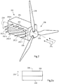
- Figure 1 shows a schematic view of an embodiment of a wind power plant 100 according to the present application with an embodiment of a nacelle 101 according to the present application.
- the wind power plant 100 is in particular an offshore wind power plant 100.
- the illustrated wind power installation 100 has a tower 120 which is arranged on a foundation 122.
- the nacelle 101 is rotatably attached to the tower 120 via a wind direction tracking device 118.
- the wind direction tracking device 118 is set up in particular to align the nacelle 101 and the rotor 106 arranged thereon, comprising a hub 108 and rotor blades 110, depending on the current wind direction for an optimal power yield.
- the wind direction tracking device 118 can comprise at least one servomotor for aligning the nacelle 101.
- the wind power plant 100 can have a measuring device (not shown) (eg wind direction transmitter) in order to measure at least the current wind direction and provide it to the wind direction tracking device 118.
- the nacelle 101 comprises a housing 104 with an outer side 105 and an inner side.
- a multiplicity of components 112, 114, 116 to be cooled can be arranged in the interior of the housing 101.
- a transmission 112, a generator 114 and a transformer 116 are arranged. Because of the heat generated during the operation of these mechanical and / or electrical components 112, 114, 116, cooling of the components 112, 114, 116 is necessary.
- a plurality of cooling fins 102 are arranged in particular on the outside 105 for cooling (only two cooling fins 102 are shown for a better overview).
- the cooling fins 102 are arranged horizontally in the present exemplary embodiment.
- the cooling fins 102 are arranged parallel to the rotor axis 126.
- a cooling fin 102 can preferably be formed from a metal and, for example, can be materially bonded (for example by a welded connection) to the outside 105 of the housing 104.
- a heat conduction is formed from the respective component 112, 114, 116 to the inside of the housing 104.
- the heat conducted to the inside can then be dissipated via the at least one cooling fin 102 arranged on the outside 105 by the air flow / wind.
- the heat conduction can be established in different ways.
- at least one gas connection (preferably air connection) is formed between the component 112, 114, 116 to be cooled and the inside of the housing 104.
- one or more breakthroughs / openings can be provided in the housing 104 of the nacelle 101 in order to direct an air flow from the component 112, 114, 116 to the inside (and back again) to be cooled allow.
- a component 112, 114, 116 to be cooled does not need to be completely enclosed.
- the air flow can be additionally supported by active means (e.g. fan).
- the arrangement of the components 112, 114, 116 in the housing 104 can be changed compared to the prior art.
- the at least one component which represents a heat source of a component 112, 114, 116 to be cooled, can be arranged in the vicinity of the inside of the housing 104.
- the inside of the housing 104 can be contacted by this component directly (or via, for example, a metallic heat conductor). In this way, particularly good heat conduction to the cooling fins 102 can be established.
- the Figure 2 schematically shows a further, particularly preferred embodiment of a gondola 201 according to the present application.
- the at least one component which is arranged in the housing 204 of the nacelle 201 and is to be cooled has not been shown. However, as described above, this can have heat conduction to the inside of the housing 204.
- a plurality of cooling fins 202.1 to 202.6 are attached to the outside 205 of the housing 204. It goes without saying that, according to other variants of the application, further cooling fins (not shown) can be arranged on a further area of the outside 205 of the housing 204. The selection of the areas of the outside on which one or more cooling fins are arranged can depend on the proximity of the components to be cooled arranged in the housing 204 and / or on further components arranged on the outside 205, such as measuring device (s).
- the arrangement of the cooling fins 202.1 to 202.6 shown schematically provides a particularly good cooling effect.
- the cooling fins 202.1 to 202.6 are at an angle of inclination compared to the (horizontal) rotor axis 226 228 inclined.
- all of the cooling fins 202.1 to 202.6 are aligned essentially parallel to one another.
- the angle of inclination 228 is preferably between 5 ° and 20 °.
- a staggered arrangement (from small to large) of the cooling fins 202.1 to 202.6 is preferably also provided.
- a first cooling fin 202.1 in particular has a lower height 230 compared to a further cooling fin 202.2 to 202.6.
- the height 230 of the cooling fin 202.2 is less than the height 230 of the cooling fins 202.3 to 202.6
- the height 230 of the cooling fin 202.3 is less than the height 230 of the cooling fins 202.4 to 202.6
- the height 230 of the cooling fin 202.4 is less than the height 230 of the Cooling fins 202.5 to 202.6
- the height 230 of the cooling fin 202.5 less than the height 230 of the cooling fin 202.6.
- FIG. 3 shows a side view of an exemplary cooling fin 202.
- the cooling fin 200 shown is formed flat. In the present case it has a planar or flat side profile. In principle, other forms are also conceivable.
- the height of the cooling fin 202 is denoted by the reference number 230 and the length of the cooling fin 202 is denoted by the reference number 232.
- the center 234 of the length 232 is denoted by the reference numeral 234.
- the height 230 of the first cooling fin 202.1 is lower in comparison to the further cooling fin 202.2.
- the distance between the rotor 206, in particular the plane spanned by the rotor blades 210, and the first cooling fin 202.1, in particular the center 234 of the length 232 of the first cooling fin 202.1 is less than the distance between the rotor 206, in particular the plane spanned by the rotor blades 210 and the further (directly adjacent) cooling rib 202.2, in particular the center 234 of the length 232 of the further cooling rib 202.2.
- a staggered arrangement can preferably be present.
- the height 230 of the cooling fins 202.1 to 202.6 can increase with increasing distance (e.g. continuously).
- the cooling fin 202.6 with the greatest distance from the rotor 206 can have the greatest height 230 and the cooling fin 202.1 with the smallest distance from the rotor 206 can have the lowest height 230, which are preferably between 20% and 50% of the maximum height 230 of the cooling fin 202.6 can.
- the air flow or wind can be used optimally for cooling the components to be cooled which are arranged in the housing.
Landscapes
- Engineering & Computer Science (AREA)
- Physics & Mathematics (AREA)
- Thermal Sciences (AREA)
- Life Sciences & Earth Sciences (AREA)
- Sustainable Development (AREA)
- Sustainable Energy (AREA)
- Chemical & Material Sciences (AREA)
- Combustion & Propulsion (AREA)
- Mechanical Engineering (AREA)
- General Engineering & Computer Science (AREA)
- Wind Motors (AREA)
Claims (12)
- Nacelle (101, 201) d'éolienne (100), comprenant :- au moins un boîtier (104, 204) présentant une face extérieure (105, 205) et une face intérieure, et- au moins un composant (112, 114, 116) disposé à l'intérieur du boîtier (104, 204) et devant être refroidi,- où au moins deux ailettes de refroidissement (102, 202, 202.1, 202.2, 202.3, 202.4, 202.5, 202.6) sont disposées au niveau de la face extérieure (105, 205) du boîtier (104, 204),- au moins deux ailettes de refroidissement (102, 202, 202. 1, 202.2, 202.3, 202.4, 202.5, 202.6) sont disposées parallèlement à l'axe du rotor (126, 226) ou au moins une ailette de refroidissement (102, 202, 202.1, 202.2, 202.3, 202.4, 202.5, 202.6) est inclinée par rapport à l'axe du rotor (126, 226) d'un angle d'inclinaison (228), l'angle d'inclinaison (228) étant compris entre 2° et 85°,
caractérisée- en ce qu'une première ailette de refroidissement (102, 202, 202.1, 202.2, 202.3, 202.4, 202.5, 202.6) a une distance plus faible par rapport à un rotor (106, 206) disposé au niveau de la nacelle (101, 201) que l'au moins une autre ailette de refroidissement (102, 202, 202.1, 202.2, 202.3, 202.4, 202.5, 202.6),- et la hauteur (230) de la première ailette de refroidissement (102, 202, 202.1, 202.2, 202.3, 202.4, 202.5, 202.6) est au moins inférieure à la hauteur (230) de l'au moins une autre ailette de refroidissement (102, 202, 202.1, 202.2, 202.3, 202.4, 202.5, 202.6). - Nacelle (101, 201) selon la revendication 1, caractérisée en ce que l'angle d'inclinaison (228) est compris entre 5° et 65°.
- Nacelle (101, 201) selon la revendication 2, caractérisée en ce que l'angle d'inclinaison est compris entre 5° et 20°.
- Nacelle (101, 201) selon la revendication 1, 2 ou 3, caractérisée en ce qu'une pluralité d'ailettes de refroidissement (102, 202, 202.1, 202.2, 202.3, 202.4, 202.5, 202.6) sont inclinées par rapport à l'axe du rotor (126, 226) du même angle d'inclinaison (228).
- Nacelle (101, 201) selon l'une des revendications précédentes, caractérisée en ce que- l'au moins un composant (112, 114, 116) à refroidir est au moins un composant mécanique (112),
et/ou- l'au moins un composant (112, 114, 116) à refroidir est au moins un composant électrique (114, 116). - Nacelle (101, 201) selon la revendication 5, caractérisée en ce que le composant mécanique (112) est une transmission (112).
- Nacelle (101, 201) selon la revendication 5, caractérisée en ce que le composant électrique (114, 116) est un transformateur (116) ou un générateur (114).
- Nacelle (101, 201) selon l'une des revendications précédentes, caractérisée en ce qu'une conduction thermique est formée entre une face intérieure du boîtier (104, 204) et l'au moins un composant (112, 114, 116) à refroidir.
- Nacelle (101, 201) selon la revendication 8, caractérisée en ce que la conduction thermique est formée par une connexion gazeuse.
- Installation éolienne (100) comprenant une nacelle (101, 201) selon l'une des revendications précédentes.
- Installation éolienne (100) selon la revendication 10, caractérisée en ce que l'installation éolienne (100) est une installation éolienne offshore (100).
- Utilisation d'au moins deux ailettes de refroidissement (102, 202, 202.1, 202.2, 202.3, 202.4, 202.5, 202.6) disposées sur une face extérieure (105, 205) d'un boîtier (104, 204) d'une nacelle (101, 201) d'une éolienne (100) pour refroidir au moins un composant (112, 114, 116) à refroidir disposé dans le boîtier (104, 204), où une première ailette de refroidissement (102, 202, 202.1, 202.2, 202.3, 202.4, 202.5, 202.6) a une distance plus faible par rapport à un rotor (106, 206) disposé au niveau de la nacelle (101, 201) que l'au moins une autre ailette de refroidissement (102, 202, 202.1, 202.2, 202.3, 202.4, 202.5, 202.6), la hauteur (230) de la première ailette de refroidissement (102, 202, 202.1, 202.2, 202.3, 202.4, 202.5, 202.6) est au moins inférieure à la hauteur (230) de l'au moins une autre ailette de refroidissement (102, 202, 202.1, 202.2, 202.3, 202.4, 202.5, 202.6), où au moins deux ailettes de refroidissement (102, 202, 202.1, 202.2, 202.3, 202.4, 202.5, 202. 6) sont disposées parallèlement à l'axe du rotor (126, 226) ou au moins une ailette de refroidissement (102, 202, 202.1, 202.2, 202.3, 202.4, 202.5, 202.6) est inclinée par rapport à l'axe du rotor (126, 226) d'un angle d'inclinaison (228), l'angle d'inclinaison (228) étant compris entre 2° et 85°.
Priority Applications (1)
| Application Number | Priority Date | Filing Date | Title |
|---|---|---|---|
| PL18700128T PL3571402T3 (pl) | 2017-01-23 | 2018-01-09 | Gondola elektrowni wiatrowej |
Applications Claiming Priority (2)
| Application Number | Priority Date | Filing Date | Title |
|---|---|---|---|
| DE102017101207.9A DE102017101207A1 (de) | 2017-01-23 | 2017-01-23 | Gondel einer windkraftanlage |
| PCT/EP2018/050452 WO2018134083A1 (fr) | 2017-01-23 | 2018-01-09 | Nacelle d'éolienne |
Publications (2)
| Publication Number | Publication Date |
|---|---|
| EP3571402A1 EP3571402A1 (fr) | 2019-11-27 |
| EP3571402B1 true EP3571402B1 (fr) | 2021-03-03 |
Family
ID=60937784
Family Applications (1)
| Application Number | Title | Priority Date | Filing Date |
|---|---|---|---|
| EP18700128.4A Not-in-force EP3571402B1 (fr) | 2017-01-23 | 2018-01-09 | Nacelle d'éolienne |
Country Status (5)
| Country | Link |
|---|---|
| EP (1) | EP3571402B1 (fr) |
| DE (1) | DE102017101207A1 (fr) |
| ES (1) | ES2863455T3 (fr) |
| PL (1) | PL3571402T3 (fr) |
| WO (1) | WO2018134083A1 (fr) |
Family Cites Families (8)
| Publication number | Priority date | Publication date | Assignee | Title |
|---|---|---|---|---|
| DE10124268B4 (de) * | 2001-05-18 | 2006-02-09 | Wobben, Aloys, Dipl.-Ing. | Generatorkühlung |
| DE10351844A1 (de) * | 2003-11-06 | 2005-06-09 | Alstom | Windkraftanlage |
| US7345376B2 (en) * | 2004-11-30 | 2008-03-18 | Distributed Energy Systems Corporation | Passively cooled direct drive wind turbine |
| CN101627208A (zh) * | 2006-12-22 | 2010-01-13 | 高技术投资公司 | 多发电机式风轮机 |
| ITMI20081122A1 (it) * | 2008-06-19 | 2009-12-20 | Rolic Invest Sarl | Generatore eolico provvisto di un impianto di raffreddamento |
| US8403638B2 (en) * | 2010-06-30 | 2013-03-26 | Mitsubishi Heavy Industries, Ltd. | Wind power generator |
| CN104379926A (zh) * | 2012-01-13 | 2015-02-25 | 尤文能量有限公司 | 一种风力涡轮机的冷却系统 |
| KR101434443B1 (ko) * | 2012-12-27 | 2014-08-28 | 삼성중공업 주식회사 | 열 교환기를 이용한 공랭식 나셀 냉각장치 |
-
2017
- 2017-01-23 DE DE102017101207.9A patent/DE102017101207A1/de not_active Withdrawn
-
2018
- 2018-01-09 PL PL18700128T patent/PL3571402T3/pl unknown
- 2018-01-09 EP EP18700128.4A patent/EP3571402B1/fr not_active Not-in-force
- 2018-01-09 ES ES18700128T patent/ES2863455T3/es active Active
- 2018-01-09 WO PCT/EP2018/050452 patent/WO2018134083A1/fr not_active Ceased
Non-Patent Citations (1)
| Title |
|---|
| None * |
Also Published As
| Publication number | Publication date |
|---|---|
| DE102017101207A1 (de) | 2018-07-26 |
| EP3571402A1 (fr) | 2019-11-27 |
| ES2863455T3 (es) | 2021-10-11 |
| WO2018134083A1 (fr) | 2018-07-26 |
| PL3571402T3 (pl) | 2021-09-13 |
Similar Documents
| Publication | Publication Date | Title |
|---|---|---|
| EP1200733B2 (fr) | Eolienne a circuit de refroidissement ferme | |
| DE19932394C2 (de) | Windenergieanlage mit einem geschlossenen Kühlkreislauf | |
| DE10000370A1 (de) | Windenergieanlage mit einem geschlossenen Kühlkreislauf | |
| WO1999030031A1 (fr) | Eolienne et procede de refroidissement d'un generateur d'une eolienne | |
| WO2002095222A1 (fr) | Dispositif de refroidissement conçu pour un aerogenerateur | |
| DE102017004800A1 (de) | Gondelkomponente für eine Windenergieanlage und Verfahren zum Montieren einer Gondelkomponente | |
| DE102011053978B4 (de) | Kühlstruktur für eine segmentierte Statorbaugruppe | |
| EP3397859B1 (fr) | Éolienne et dispositif de refroidissement d'une éolienne | |
| EP3472462B1 (fr) | Eolienne à structure modulaire | |
| EP2990644A1 (fr) | Éolienne | |
| EP3308449B1 (fr) | Anneau de stator pour générateur électrique et générateur et éolienne équipé de celui-ci | |
| EP4015818B1 (fr) | Éolienne | |
| EP3571402B1 (fr) | Nacelle d'éolienne | |
| EP3317533B1 (fr) | Éolienne et dispositif de refroidissement pour une éolienne | |
| WO2005124799A2 (fr) | Dispositif de refroidissement de composants d'installations eoliennes | |
| EP3560051B1 (fr) | Sous-station, procédé et dispositif pour sous-station | |
| WO2016203035A1 (fr) | Tour d'éolienne et éolienne | |
| DE102018202691A1 (de) | Stromgeneratoranordnung mit Kühlsystem | |
| EP3837163A1 (fr) | Dispositif d'entraînement pour un navire et procédé de fonctionnement d'un tel dispositif d'entraînement | |
| DE112014000368T5 (de) | Windturbinengeneratorsystem | |
| EP4067650A1 (fr) | Dispositif de refroidissement d'air, générateur, dispositif de guidage d'air, éolienne et procédé de fabrication d'un générateur et d'une éolienne | |
| DE102013205966A1 (de) | Stator für eine elektrische Maschine | |
| WO2017037109A1 (fr) | Éolienne et procédé de commande du refroidissement d'une éolienne | |
| DE102012102876A1 (de) | Windkraftanlage mit zwei Rotoren | |
| DE102019208619A1 (de) | Wärmetauscher, Verfahren zum Herstellen eines Wärmetauschers sowie Kraftwerk mit einem solchen Wärmetauscher |
Legal Events
| Date | Code | Title | Description |
|---|---|---|---|
| STAA | Information on the status of an ep patent application or granted ep patent |
Free format text: STATUS: UNKNOWN |
|
| STAA | Information on the status of an ep patent application or granted ep patent |
Free format text: STATUS: THE INTERNATIONAL PUBLICATION HAS BEEN MADE |
|
| PUAI | Public reference made under article 153(3) epc to a published international application that has entered the european phase |
Free format text: ORIGINAL CODE: 0009012 |
|
| STAA | Information on the status of an ep patent application or granted ep patent |
Free format text: STATUS: REQUEST FOR EXAMINATION WAS MADE |
|
| 17P | Request for examination filed |
Effective date: 20190517 |
|
| AK | Designated contracting states |
Kind code of ref document: A1 Designated state(s): AL AT BE BG CH CY CZ DE DK EE ES FI FR GB GR HR HU IE IS IT LI LT LU LV MC MK MT NL NO PL PT RO RS SE SI SK SM TR |
|
| GRAP | Despatch of communication of intention to grant a patent |
Free format text: ORIGINAL CODE: EPIDOSNIGR1 |
|
| STAA | Information on the status of an ep patent application or granted ep patent |
Free format text: STATUS: GRANT OF PATENT IS INTENDED |
|
| INTG | Intention to grant announced |
Effective date: 20200804 |
|
| RAP1 | Party data changed (applicant data changed or rights of an application transferred) |
Owner name: RWE RENEWABLES GMBH |
|
| GRAS | Grant fee paid |
Free format text: ORIGINAL CODE: EPIDOSNIGR3 |
|
| GRAA | (expected) grant |
Free format text: ORIGINAL CODE: 0009210 |
|
| STAA | Information on the status of an ep patent application or granted ep patent |
Free format text: STATUS: THE PATENT HAS BEEN GRANTED |
|
| AK | Designated contracting states |
Kind code of ref document: B1 Designated state(s): AL AT BE BG CH CY CZ DE DK EE ES FI FR GB GR HR HU IE IS IT LI LT LU LV MC MK MT NL NO PL PT RO RS SE SI SK SM TR |
|
| REG | Reference to a national code |
Ref country code: GB Ref legal event code: FG4D Free format text: NOT ENGLISH |
|
| REG | Reference to a national code |
Ref country code: AT Ref legal event code: REF Ref document number: 1367477 Country of ref document: AT Kind code of ref document: T Effective date: 20210315 Ref country code: CH Ref legal event code: EP |
|
| REG | Reference to a national code |
Ref country code: DE Ref legal event code: R096 Ref document number: 502018004125 Country of ref document: DE |
|
| REG | Reference to a national code |
Ref country code: IE Ref legal event code: FG4D Free format text: LANGUAGE OF EP DOCUMENT: GERMAN |
|
| REG | Reference to a national code |
Ref country code: LT Ref legal event code: MG9D |
|
| PG25 | Lapsed in a contracting state [announced via postgrant information from national office to epo] |
Ref country code: NO Free format text: LAPSE BECAUSE OF FAILURE TO SUBMIT A TRANSLATION OF THE DESCRIPTION OR TO PAY THE FEE WITHIN THE PRESCRIBED TIME-LIMIT Effective date: 20210603 Ref country code: LT Free format text: LAPSE BECAUSE OF FAILURE TO SUBMIT A TRANSLATION OF THE DESCRIPTION OR TO PAY THE FEE WITHIN THE PRESCRIBED TIME-LIMIT Effective date: 20210303 Ref country code: HR Free format text: LAPSE BECAUSE OF FAILURE TO SUBMIT A TRANSLATION OF THE DESCRIPTION OR TO PAY THE FEE WITHIN THE PRESCRIBED TIME-LIMIT Effective date: 20210303 Ref country code: FI Free format text: LAPSE BECAUSE OF FAILURE TO SUBMIT A TRANSLATION OF THE DESCRIPTION OR TO PAY THE FEE WITHIN THE PRESCRIBED TIME-LIMIT Effective date: 20210303 Ref country code: GR Free format text: LAPSE BECAUSE OF FAILURE TO SUBMIT A TRANSLATION OF THE DESCRIPTION OR TO PAY THE FEE WITHIN THE PRESCRIBED TIME-LIMIT Effective date: 20210604 Ref country code: BG Free format text: LAPSE BECAUSE OF FAILURE TO SUBMIT A TRANSLATION OF THE DESCRIPTION OR TO PAY THE FEE WITHIN THE PRESCRIBED TIME-LIMIT Effective date: 20210603 |
|
| REG | Reference to a national code |
Ref country code: NL Ref legal event code: MP Effective date: 20210303 |
|
| PG25 | Lapsed in a contracting state [announced via postgrant information from national office to epo] |
Ref country code: SE Free format text: LAPSE BECAUSE OF FAILURE TO SUBMIT A TRANSLATION OF THE DESCRIPTION OR TO PAY THE FEE WITHIN THE PRESCRIBED TIME-LIMIT Effective date: 20210303 Ref country code: LV Free format text: LAPSE BECAUSE OF FAILURE TO SUBMIT A TRANSLATION OF THE DESCRIPTION OR TO PAY THE FEE WITHIN THE PRESCRIBED TIME-LIMIT Effective date: 20210303 Ref country code: RS Free format text: LAPSE BECAUSE OF FAILURE TO SUBMIT A TRANSLATION OF THE DESCRIPTION OR TO PAY THE FEE WITHIN THE PRESCRIBED TIME-LIMIT Effective date: 20210303 |
|
| PG25 | Lapsed in a contracting state [announced via postgrant information from national office to epo] |
Ref country code: NL Free format text: LAPSE BECAUSE OF FAILURE TO SUBMIT A TRANSLATION OF THE DESCRIPTION OR TO PAY THE FEE WITHIN THE PRESCRIBED TIME-LIMIT Effective date: 20210303 |
|
| REG | Reference to a national code |
Ref country code: ES Ref legal event code: FG2A Ref document number: 2863455 Country of ref document: ES Kind code of ref document: T3 Effective date: 20211011 |
|
| PG25 | Lapsed in a contracting state [announced via postgrant information from national office to epo] |
Ref country code: EE Free format text: LAPSE BECAUSE OF FAILURE TO SUBMIT A TRANSLATION OF THE DESCRIPTION OR TO PAY THE FEE WITHIN THE PRESCRIBED TIME-LIMIT Effective date: 20210303 Ref country code: CZ Free format text: LAPSE BECAUSE OF FAILURE TO SUBMIT A TRANSLATION OF THE DESCRIPTION OR TO PAY THE FEE WITHIN THE PRESCRIBED TIME-LIMIT Effective date: 20210303 Ref country code: SM Free format text: LAPSE BECAUSE OF FAILURE TO SUBMIT A TRANSLATION OF THE DESCRIPTION OR TO PAY THE FEE WITHIN THE PRESCRIBED TIME-LIMIT Effective date: 20210303 |
|
| PG25 | Lapsed in a contracting state [announced via postgrant information from national office to epo] |
Ref country code: IS Free format text: LAPSE BECAUSE OF FAILURE TO SUBMIT A TRANSLATION OF THE DESCRIPTION OR TO PAY THE FEE WITHIN THE PRESCRIBED TIME-LIMIT Effective date: 20210703 Ref country code: PT Free format text: LAPSE BECAUSE OF FAILURE TO SUBMIT A TRANSLATION OF THE DESCRIPTION OR TO PAY THE FEE WITHIN THE PRESCRIBED TIME-LIMIT Effective date: 20210705 Ref country code: SK Free format text: LAPSE BECAUSE OF FAILURE TO SUBMIT A TRANSLATION OF THE DESCRIPTION OR TO PAY THE FEE WITHIN THE PRESCRIBED TIME-LIMIT Effective date: 20210303 Ref country code: RO Free format text: LAPSE BECAUSE OF FAILURE TO SUBMIT A TRANSLATION OF THE DESCRIPTION OR TO PAY THE FEE WITHIN THE PRESCRIBED TIME-LIMIT Effective date: 20210303 |
|
| REG | Reference to a national code |
Ref country code: DE Ref legal event code: R097 Ref document number: 502018004125 Country of ref document: DE |
|
| PLBE | No opposition filed within time limit |
Free format text: ORIGINAL CODE: 0009261 |
|
| STAA | Information on the status of an ep patent application or granted ep patent |
Free format text: STATUS: NO OPPOSITION FILED WITHIN TIME LIMIT |
|
| PG25 | Lapsed in a contracting state [announced via postgrant information from national office to epo] |
Ref country code: AL Free format text: LAPSE BECAUSE OF FAILURE TO SUBMIT A TRANSLATION OF THE DESCRIPTION OR TO PAY THE FEE WITHIN THE PRESCRIBED TIME-LIMIT Effective date: 20210303 Ref country code: DK Free format text: LAPSE BECAUSE OF FAILURE TO SUBMIT A TRANSLATION OF THE DESCRIPTION OR TO PAY THE FEE WITHIN THE PRESCRIBED TIME-LIMIT Effective date: 20210303 |
|
| 26N | No opposition filed |
Effective date: 20211206 |
|
| PG25 | Lapsed in a contracting state [announced via postgrant information from national office to epo] |
Ref country code: SI Free format text: LAPSE BECAUSE OF FAILURE TO SUBMIT A TRANSLATION OF THE DESCRIPTION OR TO PAY THE FEE WITHIN THE PRESCRIBED TIME-LIMIT Effective date: 20210303 |
|
| PGFP | Annual fee paid to national office [announced via postgrant information from national office to epo] |
Ref country code: GB Payment date: 20220125 Year of fee payment: 5 Ref country code: DE Payment date: 20220120 Year of fee payment: 5 |
|
| PG25 | Lapsed in a contracting state [announced via postgrant information from national office to epo] |
Ref country code: IS Free format text: LAPSE BECAUSE OF FAILURE TO SUBMIT A TRANSLATION OF THE DESCRIPTION OR TO PAY THE FEE WITHIN THE PRESCRIBED TIME-LIMIT Effective date: 20210703 |
|
| PGFP | Annual fee paid to national office [announced via postgrant information from national office to epo] |
Ref country code: IT Payment date: 20220124 Year of fee payment: 5 Ref country code: FR Payment date: 20220120 Year of fee payment: 5 Ref country code: ES Payment date: 20220216 Year of fee payment: 5 |
|
| PG25 | Lapsed in a contracting state [announced via postgrant information from national office to epo] |
Ref country code: MC Free format text: LAPSE BECAUSE OF FAILURE TO SUBMIT A TRANSLATION OF THE DESCRIPTION OR TO PAY THE FEE WITHIN THE PRESCRIBED TIME-LIMIT Effective date: 20210303 |
|
| PGFP | Annual fee paid to national office [announced via postgrant information from national office to epo] |
Ref country code: PL Payment date: 20211228 Year of fee payment: 5 |
|
| REG | Reference to a national code |
Ref country code: CH Ref legal event code: PL |
|
| REG | Reference to a national code |
Ref country code: BE Ref legal event code: MM Effective date: 20220131 |
|
| PG25 | Lapsed in a contracting state [announced via postgrant information from national office to epo] |
Ref country code: LU Free format text: LAPSE BECAUSE OF NON-PAYMENT OF DUE FEES Effective date: 20220109 |
|
| PG25 | Lapsed in a contracting state [announced via postgrant information from national office to epo] |
Ref country code: BE Free format text: LAPSE BECAUSE OF NON-PAYMENT OF DUE FEES Effective date: 20220131 |
|
| PG25 | Lapsed in a contracting state [announced via postgrant information from national office to epo] |
Ref country code: LI Free format text: LAPSE BECAUSE OF NON-PAYMENT OF DUE FEES Effective date: 20220131 Ref country code: CH Free format text: LAPSE BECAUSE OF NON-PAYMENT OF DUE FEES Effective date: 20220131 |
|
| PG25 | Lapsed in a contracting state [announced via postgrant information from national office to epo] |
Ref country code: IE Free format text: LAPSE BECAUSE OF NON-PAYMENT OF DUE FEES Effective date: 20220109 |
|
| REG | Reference to a national code |
Ref country code: DE Ref legal event code: R119 Ref document number: 502018004125 Country of ref document: DE |
|
| GBPC | Gb: european patent ceased through non-payment of renewal fee |
Effective date: 20230109 |
|
| PG25 | Lapsed in a contracting state [announced via postgrant information from national office to epo] |
Ref country code: GB Free format text: LAPSE BECAUSE OF NON-PAYMENT OF DUE FEES Effective date: 20230109 Ref country code: DE Free format text: LAPSE BECAUSE OF NON-PAYMENT OF DUE FEES Effective date: 20230801 |
|
| PG25 | Lapsed in a contracting state [announced via postgrant information from national office to epo] |
Ref country code: FR Free format text: LAPSE BECAUSE OF NON-PAYMENT OF DUE FEES Effective date: 20230131 |
|
| PG25 | Lapsed in a contracting state [announced via postgrant information from national office to epo] |
Ref country code: IT Free format text: LAPSE BECAUSE OF NON-PAYMENT OF DUE FEES Effective date: 20230109 |
|
| REG | Reference to a national code |
Ref country code: ES Ref legal event code: FD2A Effective date: 20240229 |
|
| REG | Reference to a national code |
Ref country code: AT Ref legal event code: MM01 Ref document number: 1367477 Country of ref document: AT Kind code of ref document: T Effective date: 20230109 |
|
| PG25 | Lapsed in a contracting state [announced via postgrant information from national office to epo] |
Ref country code: ES Free format text: LAPSE BECAUSE OF NON-PAYMENT OF DUE FEES Effective date: 20230110 |
|
| PG25 | Lapsed in a contracting state [announced via postgrant information from national office to epo] |
Ref country code: AT Free format text: LAPSE BECAUSE OF NON-PAYMENT OF DUE FEES Effective date: 20230109 |
|
| PG25 | Lapsed in a contracting state [announced via postgrant information from national office to epo] |
Ref country code: MK Free format text: LAPSE BECAUSE OF FAILURE TO SUBMIT A TRANSLATION OF THE DESCRIPTION OR TO PAY THE FEE WITHIN THE PRESCRIBED TIME-LIMIT Effective date: 20210303 Ref country code: ES Free format text: LAPSE BECAUSE OF NON-PAYMENT OF DUE FEES Effective date: 20230110 Ref country code: CY Free format text: LAPSE BECAUSE OF FAILURE TO SUBMIT A TRANSLATION OF THE DESCRIPTION OR TO PAY THE FEE WITHIN THE PRESCRIBED TIME-LIMIT Effective date: 20210303 Ref country code: AT Free format text: LAPSE BECAUSE OF NON-PAYMENT OF DUE FEES Effective date: 20230109 |
|
| PG25 | Lapsed in a contracting state [announced via postgrant information from national office to epo] |
Ref country code: PL Free format text: LAPSE BECAUSE OF NON-PAYMENT OF DUE FEES Effective date: 20230109 Ref country code: HU Free format text: LAPSE BECAUSE OF FAILURE TO SUBMIT A TRANSLATION OF THE DESCRIPTION OR TO PAY THE FEE WITHIN THE PRESCRIBED TIME-LIMIT; INVALID AB INITIO Effective date: 20180109 |
|
| PG25 | Lapsed in a contracting state [announced via postgrant information from national office to epo] |
Ref country code: MT Free format text: LAPSE BECAUSE OF FAILURE TO SUBMIT A TRANSLATION OF THE DESCRIPTION OR TO PAY THE FEE WITHIN THE PRESCRIBED TIME-LIMIT Effective date: 20210303 |
|
| PG25 | Lapsed in a contracting state [announced via postgrant information from national office to epo] |
Ref country code: TR Free format text: LAPSE BECAUSE OF FAILURE TO SUBMIT A TRANSLATION OF THE DESCRIPTION OR TO PAY THE FEE WITHIN THE PRESCRIBED TIME-LIMIT Effective date: 20210303 |
|
| PGFP | Annual fee paid to national office [announced via postgrant information from national office to epo] |
Ref country code: AT Payment date: 20260410 Year of fee payment: 5 |