EP3571864B1 - Verfahren und vorrichtung zum senden einer dateneinheit verfahren und vorrichtung zum empfangen einer dateneinheit - Google Patents
Verfahren und vorrichtung zum senden einer dateneinheit verfahren und vorrichtung zum empfangen einer dateneinheit Download PDFInfo
- Publication number
- EP3571864B1 EP3571864B1 EP18741068.3A EP18741068A EP3571864B1 EP 3571864 B1 EP3571864 B1 EP 3571864B1 EP 18741068 A EP18741068 A EP 18741068A EP 3571864 B1 EP3571864 B1 EP 3571864B1
- Authority
- EP
- European Patent Office
- Prior art keywords
- mac
- pdu
- subheader
- sdu
- data unit
- Prior art date
- Legal status (The legal status is an assumption and is not a legal conclusion. Google has not performed a legal analysis and makes no representation as to the accuracy of the status listed.)
- Active
Links
Images






Classifications
-
- H—ELECTRICITY
- H04—ELECTRIC COMMUNICATION TECHNIQUE
- H04W—WIRELESS COMMUNICATION NETWORKS
- H04W28/00—Network traffic management; Network resource management
- H04W28/02—Traffic management, e.g. flow control or congestion control
- H04W28/06—Optimizing the usage of the radio link, e.g. header compression, information sizing, discarding information
- H04W28/065—Optimizing the usage of the radio link, e.g. header compression, information sizing, discarding information using assembly or disassembly of packets
-
- H—ELECTRICITY
- H04—ELECTRIC COMMUNICATION TECHNIQUE
- H04W—WIRELESS COMMUNICATION NETWORKS
- H04W72/00—Local resource management
- H04W72/50—Allocation or scheduling criteria for wireless resources
- H04W72/54—Allocation or scheduling criteria for wireless resources based on quality criteria
- H04W72/542—Allocation or scheduling criteria for wireless resources based on quality criteria using measured or perceived quality
-
- H—ELECTRICITY
- H04—ELECTRIC COMMUNICATION TECHNIQUE
- H04L—TRANSMISSION OF DIGITAL INFORMATION, e.g. TELEGRAPHIC COMMUNICATION
- H04L5/00—Arrangements affording multiple use of the transmission path
- H04L5/003—Arrangements for allocating sub-channels of the transmission path
- H04L5/0053—Allocation of signalling, i.e. of overhead other than pilot signals
-
- H—ELECTRICITY
- H04—ELECTRIC COMMUNICATION TECHNIQUE
- H04W—WIRELESS COMMUNICATION NETWORKS
- H04W4/00—Services specially adapted for wireless communication networks; Facilities therefor
- H04W4/30—Services specially adapted for particular environments, situations or purposes
- H04W4/40—Services specially adapted for particular environments, situations or purposes for vehicles, e.g. vehicle-to-pedestrians [V2P]
- H04W4/46—Services specially adapted for particular environments, situations or purposes for vehicles, e.g. vehicle-to-pedestrians [V2P] for vehicle-to-vehicle communication [V2V]
-
- H—ELECTRICITY
- H04—ELECTRIC COMMUNICATION TECHNIQUE
- H04W—WIRELESS COMMUNICATION NETWORKS
- H04W4/00—Services specially adapted for wireless communication networks; Facilities therefor
- H04W4/70—Services for machine-to-machine communication [M2M] or machine type communication [MTC]
-
- H—ELECTRICITY
- H04—ELECTRIC COMMUNICATION TECHNIQUE
- H04W—WIRELESS COMMUNICATION NETWORKS
- H04W72/00—Local resource management
- H04W72/20—Control channels or signalling for resource management
- H04W72/23—Control channels or signalling for resource management in the downlink direction of a wireless link, i.e. towards a terminal
-
- H—ELECTRICITY
- H04—ELECTRIC COMMUNICATION TECHNIQUE
- H04L—TRANSMISSION OF DIGITAL INFORMATION, e.g. TELEGRAPHIC COMMUNICATION
- H04L1/00—Arrangements for detecting or preventing errors in the information received
- H04L1/0078—Avoidance of errors by organising the transmitted data in a format specifically designed to deal with errors, e.g. location
- H04L1/0079—Formats for control data
-
- H—ELECTRICITY
- H04—ELECTRIC COMMUNICATION TECHNIQUE
- H04L—TRANSMISSION OF DIGITAL INFORMATION, e.g. TELEGRAPHIC COMMUNICATION
- H04L45/00—Routing or path finding of packets in data switching networks
- H04L45/74—Address processing for routing
-
- H—ELECTRICITY
- H04—ELECTRIC COMMUNICATION TECHNIQUE
- H04L—TRANSMISSION OF DIGITAL INFORMATION, e.g. TELEGRAPHIC COMMUNICATION
- H04L5/00—Arrangements affording multiple use of the transmission path
- H04L5/0091—Signalling for the administration of the divided path, e.g. signalling of configuration information
-
- H—ELECTRICITY
- H04—ELECTRIC COMMUNICATION TECHNIQUE
- H04W—WIRELESS COMMUNICATION NETWORKS
- H04W4/00—Services specially adapted for wireless communication networks; Facilities therefor
- H04W4/90—Services for handling of emergency or hazardous situations, e.g. earthquake and tsunami warning systems [ETWS]
Definitions
- the present invention relates to a wireless communication system, and more particularly, to a method for transmitting or receiving a data unit and an apparatus therefor.
- LTE 3rd Generation Partnership Project Long Term Evolution
- FIG. 1 is a view schematically illustrating a network structure of an E-UMTS as an exemplary radio communication system.
- An Evolved Universal Mobile Telecommunications System (E-UMTS) is an advanced version of a conventional Universal Mobile Telecommunications System (UMTS) and basic standardization thereof is currently underway in the 3GPP.
- E-UMTS may be generally referred to as a Long Term Evolution (LTE) system.
- LTE Long Term Evolution
- the E-UMTS includes a User Equipment (UE), eNode Bs (eNBs), and an Access Gateway (AG) which is located at an end of the network (E-UTRAN) and connected to an external network.
- the eNBs may simultaneously transmit multiple data streams for a broadcast service, a multicast service, and/or a unicast service.
- One or more cells may exist per eNB.
- the cell is set to operate in one of bandwidths such as 1.25, 2.5, 5, 10, 15, and 20 MHz and provides a downlink (DL) or uplink (UL) transmission service to a plurality of UEs in the bandwidth. Different cells may be set to provide different bandwidths.
- the eNB controls data transmission or reception to and from a plurality of UEs.
- the eNB transmits DL scheduling information of DL data to a corresponding UE so as to inform the UE of a time/frequency domain in which the DL data is supposed to be transmitted, coding, a data size, and hybrid automatic repeat and request (HARQ)-related information.
- HARQ hybrid automatic repeat and request
- the eNB transmits UL scheduling information of UL data to a corresponding UE so as to inform the UE of a time/frequency domain which may be used by the UE, coding, a data size, and HARQ-related information.
- An interface for transmitting user traffic or control traffic may be used between eNBs.
- a core network (CN) may include the AG and a network node or the like for user registration of UEs.
- the AG manages the mobility of a UE on a tracking area (TA) basis.
- One TA includes a plurality of cells.
- WCDMA wideband code division multiple access
- next-generation RAT which takes into account such advanced mobile broadband communication, massive MTC (mMCT), and ultra-reliable and low latency communication (URLLC), is being discussed.
- mMCT massive MTC
- URLLC ultra-reliable and low latency communication
- EP3319252 A1 falls under Article 54(3) EPC and it is therefore not relevant to the question of inventive step.
- the 3GPP Draft No. R2-166824, entitled “Placement of RLC/MAC headers” discusses placement of MAC and RLC headers in a MAC PDU.
- the number of user equipments (UEs) to which a BS should provide a service in a prescribed resource region increases and the amount of data and control information that the BS should transmit to the UEs increases. Since the amount of resources available to the BS for communication with the UE(s) is limited, a new method in which the BS efficiently receives/transmits uplink/downlink data and/or uplink/downlink control information using the limited radio resources is needed.
- a transmitting device in an aspect of the present invention, provided herein is a method of transmitting, by a transmitting device, a data unit in a wireless communication system as set forth in the appended claims.
- a method of receiving, by a receiving device, a data unit in a wireless communication system as set forth in the appended claims.
- a transmitting device in a wireless communication system as set forth in the appended claims.
- a receiving device in a wireless communication system as set forth in the appended claims.
- radio communication signals can be efficiently transmitted/received. Therefore, overall throughput of a radio communication system can be improved.
- a low cost/complexity UE can perform communication with a base station (BS) at low cost while maintaining compatibility with a legacy system.
- BS base station
- the UE can be implemented at low cost/complexity.
- the UE and the BS can perform communication with each other at a narrowband.
- delay/latency occurring during communication between a user equipment and a BS may be reduce.
- a transmitting side can process medium access control (MAC) service data units (SDUs) for transmission without waiting for the MAC control element (CE) construction, thereby facilitating the fast MAC PDU processing in the transmitting side.
- MAC medium access control
- SDUs service data units
- CE MAC control element
- a receiving side can easily identify a MAC CE by processing a MAC protocol data unit (PDU) from the end to start of the MAC PDU, and this will facilitate the fast MAC CE processing in the receiving side.
- PDU MAC protocol data unit
- signals in a new radio access technology system can be transmitted/received effectively.
- CDMA code division multiple access
- FDMA frequency division multiple access
- TDMA time division multiple access
- OFDMA orthogonal frequency division multiple access
- SC-FDMA single carrier frequency division multiple access
- MC-FDMA multicarrier frequency division multiple access
- CDMA may be embodied through radio technology such as universal terrestrial radio access (UTRA) or CDMA2000.
- TDMA may be embodied through radio technology such as global system for mobile communications (GSM), general packet radio service (GPRS), or enhanced data rates for GSM evolution (EDGE).
- GSM global system for mobile communications
- GPRS general packet radio service
- EDGE enhanced data rates for GSM evolution
- OFDMA may be embodied through radio technology such as institute of electrical and electronics engineers (IEEE) 802.11 (Wi-Fi), IEEE 802.16 (WiMAX), IEEE 802.20, or evolved UTRA (E-UTRA).
- UTRA is a part of a universal mobile telecommunications system (UMTS).
- 3rd generation partnership project (3GPP) long term evolution (LTE) is a part of evolved UMTS (E-UMTS) using E-UTRA.
- 3GPP LTE employs OFDMA in DL and SC-FDMA in UL.
- LTE-advanced (LTE-A) is an evolved version of 3GPP LTE. For convenience of description, it is assumed that the present invention is applied to 3GPP LTE/LTE-A.
- the present invention is applicable to contention based communication such as Wi-Fi as well as non-contention based communication as in the 3GPP LTE/ LTE-A system in which an eNB allocates a DL/UL time/frequency resource to a UE and the UE receives a DL signal and transmits a UL signal according to resource allocation of the eNB.
- an access point (AP) or a control node for controlling the AP allocates a resource for communication between the UE and the AP
- a communication resource is occupied through contention between UEs which desire to access the AP.
- CSMA carrier sense multiple access
- CSMA refers to a probabilistic media access control (MAC) protocol for confirming, before a node or a communication device transmits traffic on a shared transmission medium (also called a shared channel) such as a frequency band, that there is no other traffic on the same shared transmission medium.
- MAC media access control
- a transmitting device determines whether another transmission is being performed before attempting to transmit traffic to a receiving device. In other words, the transmitting device attempts to detect presence of a carrier from another transmitting device before attempting to perform transmission. Upon sensing the carrier, the transmitting device waits for another transmission device which is performing transmission to finish transmission, before performing transmission thereof.
- CSMA can be a communication scheme based on the principle of "sense before transmit” or “listen before talk".
- a scheme for avoiding collision between transmitting devices in the contention based communication system using CSMA includes carrier sense multiple access with collision detection (CSMA/CD) and/or carrier sense multiple access with collision avoidance (CSMA/CA).
- CSMA/CD is a collision detection scheme in a wired local area network (LAN) environment.
- a personal computer (PC) or a server which desires to perform communication in an Ethernet environment first confirms whether communication occurs on a network and, if another device carries data on the network, the PC or the server waits and then transmits data. That is, when two or more users (e.g.
- CSMA/CD is a scheme for flexibly transmitting data by monitoring collision.
- a transmitting device using CSMA/CD adjusts data transmission thereof by sensing data transmission performed by another device using a specific rule.
- CSMA/CA is a MAC protocol specified in IEEE 802.11 standards.
- a wireless LAN (WLAN) system conforming to IEEE 802.11 standards does not use CSMA/CD which has been used in IEEE 802.3 standards and uses CA, i.e. a collision avoidance scheme.
- Transmission devices always sense carrier of a network and, if the network is empty, the transmission devices wait for determined time according to locations thereof registered in a list and then transmit data.
- Various methods are used to determine priority of the transmission devices in the list and to reconfigure priority.
- collision may occur and, in this case, a collision sensing procedure is performed.
- a transmission device using CSMA/CA avoids collision between data transmission thereof and data transmission of another transmission device using a specific rule.
- the term “assume” may mean that a subject to transmit a channel transmits the channel in accordance with the corresponding "assumption.” This may also mean that a subject to receive the channel receives or decodes the channel in a form conforming to the "assumption,” on the assumption that the channel has been transmitted according to the "assumption.”
- a user equipment may be a fixed or mobile device.
- the UE include various devices that transmit and receive user data and/or various kinds of control information to and from a base station (BS).
- the UE may be referred to as a terminal equipment (TE), a mobile station (MS), a mobile terminal (MT), a user terminal (UT), a subscriber station (SS), a wireless device, a personal digital assistant (PDA), a wireless modem, a handheld device, etc.
- a BS generally refers to a fixed station that performs communication with a UE and/or another BS, and exchanges various kinds of data and control information with the UE and another BS.
- the BS may be referred to as an advanced base station (ABS), a node-B (NB), an evolved node-B (eNB), a base transceiver system (BTS), an access point (AP), a processing server (PS), etc.
- ABS advanced base station
- NB node-B
- eNB evolved node-B
- BTS base transceiver system
- AP access point
- PS processing server
- a BS of the UMTS is referred to as a NB
- a BS of the EPC/LTE is referred to as an eNB
- a BS of the new radio (NR) system is referred to as a gNB.
- a BS will be referred to as an eNB.
- a node refers to a fixed point capable of transmitting/ receiving a radio signal through communication with a UE.
- Various types of eNBs may be used as nodes irrespective of the terms thereof.
- a BS, a node B (NB), an e-node B (eNB), a pico-cell eNB (PeNB), a home eNB (HeNB), a relay, a repeater, etc. may be a node.
- the node may not be an eNB.
- the node may be a radio remote head (RRH) or a radio remote unit (RRU).
- the RRH or RRU generally has a lower power level than a power level of an eNB.
- RRH/RRU Since the RRH or RRU (hereinafter, RRH/RRU) is generally connected to the eNB through a dedicated line such as an optical cable, cooperative communication between RRH/ RRU and the eNB can be smoothly performed in comparison with cooperative communication between eNBs connected by a radio line.
- At least one antenna is installed per node.
- the antenna may mean a physical antenna or mean an antenna port or a virtual antenna.
- a cell refers to a prescribed geographical area to which one or more nodes provide a communication service. Accordingly, in the present invention, communicating with a specific cell may mean communicating with an eNB or a node which provides a communication service to the specific cell.
- a DL/UL signal of a specific cell refers to a DL/UL signal from/to an eNB or a node which provides a communication service to the specific cell.
- a node providing UL/DL communication services to a UE is called a serving node and a cell to which UL/DL communication services are provided by the serving node is especially called a serving cell.
- a 3GPP LTE/LTE-A system uses the concept of a cell in order to manage radio resources and a cell associated with the radio resources is distinguished from a cell of a geographic region.
- a "cell” of a geographic region may be understood as coverage within which a node can provide service using a carrier and a "cell" of a radio resource is associated with bandwidth (BW) which is a frequency range configured by the carrier. Since DL coverage, which is a range within which the node is capable of transmitting a valid signal, and UL coverage, which is a range within which the node is capable of receiving the valid signal from the UE, depends upon a carrier carrying the signal, the coverage of the node may be associated with coverage of the "cell" of a radio resource used by the node. Accordingly, the term "cell" may be used to indicate service coverage of the node sometimes, a radio resource at other times, or a range that a signal using a radio resource can reach with valid strength at other times.
- the 3GPP LTE-A standard uses the concept of a cell to manage radio resources.
- the "cell" associated with the radio resources is defined by combination of downlink resources and uplink resources, that is, combination of DL component carrier (CC) and UL CC.
- the cell may be configured by downlink resources only, or may be configured by downlink resources and uplink resources.
- linkage between a carrier frequency of the downlink resources (or DL CC) and a carrier frequency of the uplink resources (or UL CC) may be indicated by system information.
- SIB2 system information block type 2
- the carrier frequency means a center frequency of each cell or CC.
- a cell operating on a primary frequency may be referred to as a primary cell (Pcell) or PCC
- a cell operating on a secondary frequency may be referred to as a secondary cell (Scell) or SCC.
- the carrier corresponding to the Pcell on downlink will be referred to as a downlink primary CC (DL PCC)
- the carrier corresponding to the Pcell on uplink will be referred to as an uplink primary CC (UL PCC).
- a Scell means a cell that may be configured after completion of radio resource control (RRC) connection establishment and used to provide additional radio resources.
- the Scell may form a set of serving cells for the UE together with the Pcell in accordance with capabilities of the UE.
- RRC radio resource control
- the carrier corresponding to the Scell on the downlink will be referred to as downlink secondary CC (DL SCC), and the carrier corresponding to the Scell on the uplink will be referred to as uplink secondary CC (UL SCC).
- DL SCC downlink secondary CC
- UL SCC uplink secondary CC
- the UE is in RRC-CONNECTED state, if it is not configured by carrier aggregation or does not support carrier aggregation, a single serving cell configured by the Pcell only exists.
- PDCCH refers to a PDCCH, an EPDCCH (in subframes when configured), a MTC PDCCH (MPDCCH), for an RN with R-PDCCH configured and not suspended, to the R-PDCCH or, for NB-IoT to the narrowband PDCCH (NPDCCH).
- MPDCCH MTC PDCCH
- NPDCCH narrowband PDCCH
- monitoring a channel implies attempting to decode the channel.
- monitoring a PDCCH implies attempting to decode PDCCH(s) (or PDCCH candidates).
- the term "special Cell” refers to the PCell of the master cell group (MCG) or the PSCell of the secondary cell group (SCG), otherwise the term Special Cell refers to the PCell.
- the MCG is a group of serving cells associated with a master eNB (MeNB) which terminates at least S1-MME
- the SCG is a group of serving cells associated with a secondary eNB (SeNB) that is providing additional radio resources for the UE but is not the MeNB.
- the SCG is comprised of a primary SCell (PSCell) and optionally one or more SCells.
- PSCell primary SCell
- two MAC entities are configured in the UE: one for the MCG and one for the SCG.
- Each MAC entity is configured by RRC with a serving cell supporting PUCCH transmission and contention based Random Access.
- the term SpCell refers to such cell, whereas the term SCell refers to other serving cells.
- the term SpCell either refers to the PCell of the MCG or the PSCell of the SCG depending on if the MAC entity is associated to the MCG or the SCG, respectively.
- C-RNTI refers to a cell RNTI
- SI-RNTI refers to a system information RNTI
- P-RNTI refers to a paging RNTI
- RA-RNTI refers to a random access RNTI
- SC-RNTI refers to a single cell RNTI
- SL-RNTI refers to a sidelink RNTI
- SPS C-RNTI refers to a semi-persistent scheduling C-RNTI.
- 3GPP LTE/LTE-A standard documents for example, 3GPP TS 36.211, 3GPP TS 36.212, 3GPP TS 36.213, 3GPP TS 36.300, 3GPP TS 36.321, 3GPP TS 36.322, 3GPP TS 36.323 and 3GPP TS 36.331, and 3GPP NR standard documents, for example, 38.xxx series may be referenced.
- FIG. 2 is a block diagram illustrating network structure of an evolved universal mobile telecommunication system (E-UMTS).
- E-UMTS may be also referred to as an LTE system.
- the communication network is widely deployed to provide a variety of communication services such as voice (VoIP) through IMS and packet data.
- VoIP voice
- IMS packet data
- the E-UMTS network includes an evolved UMTS terrestrial radio access network (E-UTRAN), an Evolved Packet Core (EPC) and one or more user equipment.
- the E-UTRAN may include one or more evolved NodeB (eNodeB) 20, and a plurality of user equipment (UE) 10 may be located in one cell.
- eNodeB evolved NodeB
- UE user equipment
- MME mobility management entity
- downlink refers to communication from eNB 20 to UE 10
- uplink refers to communication from the UE to an eNB.
- FIG. 3 is a block diagram depicting architecture of a typical E-UTRAN and a typical EPC.
- an eNB 20 provides end points of a user plane and a control plane to the UE 10.
- MME/SAE gateway 30 provides an end point of a session and mobility management function for UE 10.
- the eNB and MME/SAE gateway may be connected via an S1 interface.
- the eNB 20 is generally a fixed station that communicates with a UE 10, and may also be referred to as a base station (BS) or an access point.
- BS base station
- One eNB 20 may be deployed per cell.
- An interface for transmitting user traffic or control traffic may be used between eNBs 20.
- the MME provides various functions including NAS signaling to eNBs 20, NAS signaling security, AS Security control, Inter CN node signaling for mobility between 3GPP access networks, Idle mode UE Reachability (including control and execution of paging retransmission), Tracking Area list management (for UE in idle and active mode), PDN GW and Serving GW selection, MME selection for handovers with MME change, SGSN selection for handovers to 2G or 3G 3GPP access networks, roaming, authentication, bearer management functions including dedicated bearer establishment, support for PWS (which includes ETWS and CMAS) message transmission.
- the SAE gateway host provides assorted functions including Per-user based packet filtering (by e.g.
- MME/SAE gateway 30 will be referred to herein simply as a "gateway,” but it is understood that this entity includes both an MME and an SAE gateway.
- a plurality of nodes may be connected between eNB 20 and gateway 30 via the S1 interface.
- the eNBs 20 may be connected to each other via an X2 interface and neighboring eNBs may have a meshed network structure that has the X2 interface.
- eNB 20 may perform functions of selection for gateway 30, routing toward the gateway during a Radio Resource Control (RRC) activation, scheduling and transmitting of paging messages, scheduling and transmitting of Broadcast Channel (BCCH) information, dynamic allocation of resources to UEs 10 in both uplink and downlink, configuration and provisioning of eNB measurements, radio bearer control, radio admission control (RAC), and connection mobility control in LTE_ACTIVE state.
- gateway 30 may perform functions of paging origination, LTE-IDLE state management, ciphering of the user plane, System Architecture Evolution (SAE) bearer control, and ciphering and integrity protection of Non-Access Stratum (NAS) signaling.
- SAE System Architecture Evolution
- NAS Non-Access Stratum
- the EPC includes a mobility management entity (MME), a serving-gateway (S-GW), and a packet data network-gateway (PDN-GW).
- MME mobility management entity
- S-GW serving-gateway
- PDN-GW packet data network-gateway
- FIG. 4 is a diagram showing a control plane and a user plane of a radio interface protocol between a UE and an E-UTRAN based on a 3GPP radio access network standard.
- the control plane refers to a path used for transmitting control messages used for managing a call between the UE and the E-UTRAN.
- the user plane refers to a path used for transmitting data generated in an application layer, e.g., voice data or Internet packet data.
- Layer 1 (i.e. L1) of the LTE/LTE-A system is corresponding to a physical layer.
- a physical (PHY) layer of a first layer (Layer 1 or L1) provides an information transfer service to a higher layer using a physical channel.
- the PHY layer is connected to a medium access control (MAC) layer located on the higher layer via a transport channel. Data is transported between the MAC layer and the PHY layer via the transport channel. Data is transported between a physical layer of a transmitting side and a physical layer of a receiving side via physical channels.
- the physical channels use time and frequency as radio resources.
- the physical channel is modulated using an orthogonal frequency division multiple access (OFDMA) scheme in downlink and is modulated using a single carrier frequency division multiple access (SC-FDMA) scheme in uplink.
- OFDMA orthogonal frequency division multiple access
- SC-FDMA single carrier frequency division multiple access
- Layer 2 (i.e. L2) of the LTE/LTE-A system is split into the following sublayers: Medium Access Control (MAC), Radio Link Control (RLC) and Packet Data Convergence Protocol (PDCP).
- the MAC layer of a second layer (Layer 2 or L2) provides a service to a radio link control (RLC) layer of a higher layer via a logical channel.
- the RLC layer of the second layer supports reliable data transmission.
- a function of the RLC layer may be implemented by a functional block of the MAC layer.
- a packet data convergence protocol (PDCP) layer of the second layer performs a header compression function to reduce unnecessary control information for efficient transmission of an Internet protocol (IP) packet such as an IP version 4 (IPv4) packet or an IP version 6 (IPv6) packet in a radio interface having a relatively small bandwidth.
- IP Internet protocol
- Layer 3 of the LTE/LTE-A system includes the following sublayers: Radio Resource Control (RRC) and Non Access Stratum (NAS).
- RRC Radio Resource Control
- NAS Non Access Stratum
- a radio resource control (RRC) layer located at the bottom of a third layer is defined only in the control plane.
- the RRC layer controls logical channels, transport channels, and physical channels in relation to configuration, re-configuration, and release of radio bearers (RBs).
- An RB refers to a service that the second layer provides for data transmission between the UE and the E-UTRAN.
- the RRC layer of the UE and the RRC layer of the E-UTRAN exchange RRC messages with each other.
- the non-access stratum (NAS) layer positioned over the RRC layer performs functions such as session management and mobility management.
- Radio bearers are roughly classified into (user) data radio bearers (DRBs) and signaling radio bearers (SRBs). SRBs are defined as radio bearers (RBs) that are used only for the transmission of RRC and NAS messages.
- DRBs data radio bearers
- SRBs signaling radio bearers
- One cell of the eNB is set to operate in one of bandwidths such as 1.25, 2.5, 5, 10, 15, and 20 MHz and provides a downlink or uplink transmission service to a plurality of UEs in the bandwidth. Different cells may be set to provide different bandwidths.
- Downlink transport channels for transmission of data from the E-UTRAN to the UE include a broadcast channel (BCH) for transmission of system information, a paging channel (PCH) for transmission of paging messages, and a downlink shared channel (SCH) for transmission of user traffic or control messages.
- BCH broadcast channel
- PCH paging channel
- SCH downlink shared channel
- Traffic or control messages of a downlink multicast or broadcast service may be transmitted through the downlink SCH and may also be transmitted through a separate downlink multicast channel (MCH).
- MCH downlink multicast channel
- Uplink transport channels for transmission of data from the UE to the E-UTRAN include a random access channel (RACH) for transmission of initial control messages and an uplink SCH for transmission of user traffic or control messages.
- Logical channels that are defined above the transport channels and mapped to the transport channels include a broadcast control channel (BCCH), a paging control channel (PCCH), a common control channel (CCCH), a multicast control channel (MCCH), and a multicast traffic channel (MTCH).
- BCCH broadcast control channel
- PCCH paging control channel
- CCCH common control channel
- MCCH multicast control channel
- MTCH multicast traffic channel
- FIG. 5 is a view showing an example of a physical channel structure used in an E-UMTS system.
- a physical channel includes several subframes on a time axis and several subcarriers on a frequency axis.
- one subframe includes a plurality of symbols on the time axis.
- One subframe includes a plurality of resource blocks and one resource block includes a plurality of symbols and a plurality of subcarriers.
- each subframe may use certain subcarriers of certain symbols (e.g., a first symbol) of a subframe for a physical downlink control channel (PDCCH), that is, an L1/L2 control channel.
- the PDCCH carries scheduling assignments and other control information.
- PDCCH physical downlink control channel
- an L1/L2 control information transmission area (PDCCH) and a data area (PDSCH) are shown.
- a radio frame of 10ms is used and one radio frame includes 10 subframes.
- one subframe includes two consecutive slots. The length of one slot may be 0.5ms.
- one subframe includes a plurality of OFDM symbols and a portion (e.g., a first symbol) of the plurality of OFDM symbols may be used for transmitting the L1/L2 control information.
- a time interval in which one subframe is transmitted is defined as a transmission time interval (TTI).
- Time resources may be distinguished by a radio frame number (or radio frame index), a subframe number (or subframe index), a slot number (or slot index), and the like.
- TTI refers to an interval during which data may be scheduled. For example, in the current LTE/LTE-A system, an opportunity of transmission of an UL grant or a DL grant is present every 1 ms, and the UL/DL grant opportunity does not exists several times in less than 1 ms. Therefore, the TTI in the legacy LTE/LTE-A system is 1ms.
- a base station and a UE mostly transmit/receive data via a PDSCH, which is a physical channel, using a DL-SCH which is a transmission channel, except a certain control signal or certain service data.
- a certain PDCCH is CRC-masked with a radio network temporary identity (RNTI) "A" and information about data is transmitted using a radio resource "B" (e.g., a frequency location) and transmission format information "C" (e.g., a transmission block size, modulation, coding information or the like) via a certain subframe.
- RNTI radio network temporary identity
- C transmission format information
- one or more UEs located in a cell monitor the PDCCH using its RNTI information.
- a specific UE with RNTI "A” reads the PDCCH and then receive the PDSCH indicated by B and C in the PDCCH information.
- a PDCCH addressed to a certain RNTI means that the PDCCH is CRC-masked with the certain RNTI.
- a UE may attempt to decode a PDCCH using the certain RNTI if the UE is monitoring a PDCCH addressed to the certain RNTI.
- FIG. 6 is a diagram for medium access control (MAC) structure overview in a UE side.
- MAC medium access control
- the MAC layer supports the following functions: mapping between logical channels and transport channels; multiplexing of MAC SDUs from one or different logical channels onto transport blocks (TB) to be delivered to the physical layer on transport channels; demultiplexing of MAC SDUs from one or different logical channels from transport blocks (TB) delivered from the physical layer on transport channels; scheduling information reporting (e.g. scheduling request, buffer status reporting); error correction through HARQ; priority handling between UEs by means of dynamic scheduling; priority handling between logical channels of one MAC entity; Logical Channel Prioritization (LCP); transport format selection; and radio resource selection for sidelink (SL).
- mapping between logical channels and transport channels multiplexing of MAC SDUs from one or different logical channels onto transport blocks (TB) to be delivered to the physical layer on transport channels
- scheduling information reporting e.g. scheduling request, buffer status reporting
- error correction through HARQ HARQ
- the MAC provides services to the RLC in the form of logical channels.
- a logical channel is defined by the type of information it carries and is generally classified as a control channel, used for transmission of control and configuration information necessary for operating an LTE system, or as a traffic channel, used for the user data.
- the set of logical channel types specified for LTE includes broadcast control channel (BCCH), paging control channel (PCCH), common control channel (CCCH), dedicated control channel (DCCH), multicast control channel (MCCH), dedicated traffic channel (DTCH), multicast traffic channel (MTCH).
- BCCH broadcast control channel
- PCCH paging control channel
- CCCH common control channel
- DCCH dedicated control channel
- MCCH multicast control channel
- DTCH dedicated traffic channel
- MTCH multicast traffic channel
- the MAC layer uses services in the form of transport channels.
- a transport channel is defined by how and with what characteristics the information is transmitted over the radio interface. Data on a transport channel is organized into transport blocks. In each transmission time interval (TTI), at most one transport block of dynamic size is transmitted over the radio interface to/from a terminal in the absence of spatial multiplexing. In the case of spatial multiplexing (MIMO), there can be up to two transport blocks per TTI.
- TTI transmission time interval
- MIMO spatial multiplexing
- transport format Associated with each transport block is a transport format (TF), specifying how the transport block is to be transmitted over the radio interface.
- the transport format includes information about the transport-block size, the modulation-and-coding scheme, and the antenna mapping. By varying the transport format, the MAC layer can thus realize different data rates. Rate control is therefore also known as transport-format selection.
- each logical channel has its own RLC entity
- the MAC layer handles the corresponding demultiplexing and forwards the RLC PDUs to their respective RLC entity for in-sequence delivery and the other functions handled by the RLC.
- a MAC is used.
- To each RLC PDU there is an associated sub-header in the MAC header.
- the sub-header contains the identity of the logical channel (LCID) from which the RLC PDU originated and the length of the PDU in bytes. There is also a flag indicating whether this is the last sub-header or not.
- the MAC layer can also insert the so-called MAC control elements into the transport blocks to be transmitted over the transport channels.
- a MAC control element is used for inband control signaling - for example, timing-advance commands and random-access response. Control elements are identified with reserved values in the LCID field, where the LCID value indicates the type of control information.
- the length field in the sub-header is removed for control elements with a fixed length.
- the MAC multiplexing functionality is also responsible for handling of multiple component carriers in the case of carrier aggregation.
- the basic principle for carrier aggregation is independent processing of the component carriers in the physical layer, including control signaling, scheduling and hybrid-ARQ retransmissions, while carrier aggregation is invisible to RLC and PDCP.
- Carrier aggregation is therefore mainly seen in the MAC layer, where logical channels, including any MAC control elements, are multiplexed to form one (two in the case of spatial multiplexing) transport block(s) per component carrier with each component carrier having its own hybrid-ARQ entity.
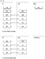
- FIG. 7 is a diagram for a MAC PDU structure used in the LTE/LTE-A system.
- FIG. 8 are examples of MAC subheaders used in the LTE/LTE-A system.
- a MAC PDU is a bit string that is byte aligned (i.e. multiple of 8 bits) in length.
- bit strings are represented by tables in which the most significant bit is the leftmost bit of the first line of the table, the least significant bit is the rightmost bit on the last line of the table, and more generally the bit string is to be read from left to right and then in the reading order of the lines.
- the bit order of each parameter field within a MAC PDU is represented with the first and most significant bit in the leftmost bit and the last and least significant bit in the rightmost bit.
- MAC SDUs are bit strings that are byte aligned (i.e. multiple of 8 bits) in length. An SDU is included into a MAC PDU from the first bit onward. The MAC entity shall ignore the value of reserved bits in downlink MAC PDUs.
- a MAC PDU consists of a MAC header, zero or more MAC service data units (MAC SDUs), zero, or more MAC control elements (MAC CEs), and optionally padding, as described in FIG. 7 . Both the MAC header and the MAC SDUs are of variable sizes.
- a MAC PDU header consists of one or more MAC PDU subheaders; each subheader corresponds to either a MAC SDU, a MAC control element or padding.
- a MAC PDU subheader consists of the five or six header fields R/ F2/E/LCID/(F)/L but for the last subheader in the MAC PDU and for fixed sized MAC control elements.
- the last subheader in the MAC PDU and subheaders for fixed sized MAC control elements consist solely of the four header fields R/F2/E/LCID.
- a MAC PDU subheader corresponding to padding consists of the four header fields R/ F2/E/LCID.
- MAC PDU subheaders have the same order as the corresponding MAC SDUs, MAC control elements and padding.
- MAC control elements are always placed before any MAC SDU.
- Padding occurs at the end of the MAC PDU, except when single-byte or two-byte padding is required. Padding may have any value and the MAC entity shall ignore it. When padding is performed at the end of the MAC PDU, zero or more padding bytes are allowed. In the LTE/LTE-A system, when single-byte or two-byte padding is required, one or two MAC PDU subheaders corresponding to padding are placed at the beginning of the MAC PDU before any other MAC PDU subheader. A maximum of one MAC PDU can be transmitted per TB per MAC entity. A maximum of one MCH MAC PDU can be transmitted per TTI.
- a fully mobile and connected society is expected in the near future, which will be characterized by a tremendous amount of growth in connectivity, traffic volume and a much broader range of usage scenarios. Some typical trends include explosive growth of data traffic, great increase of connected devices and continuous emergence of new services. Besides the market requirements, the mobile communication society itself also requires a sustainable development of the eco-system, which produces the needs to further improve system efficiencies, such as spectrum efficiency, energy efficiency, operational efficiency and cost efficiency. To meet the above ever-increasing requirements from market and mobile communication society, next generation access technologies are expected to emerge in the near future.
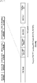
- FIG. 9 illustrates an overall procedure of the MAC PDU construction process in the LTE/LTE-A system.
- a MAC PDU construction process at a UE starts when a UL grant is received, as follows.
- the MAC PDU construction process in the LTE/LTE-A system has the following problems and/or redundancies.
- a UE can start the MAC PDU construction process only after the UE receives a UL grant.
- RLC segmentation and concatenation process starts only after the MAC entity indicates the RLC PDU size to the RLC entity, which takes long time before MAC PDU construction. Due to the variable length nature of MAC SDU and MAC subheaders, determining a RLC PDU size for each RLC entity is very complex. A MAC PDU cannot be delivered to the PHY until whole the MAC PDU is constructed, because all the MAC subheaders should be collected together and put into the front of the MAC PDU.
- a PDCP SN is already included in a RLC SDU, and adding another SN in the RLC is redundant.
- the same function is spread over two layers (MAC and RLC), which is redundant and inefficient, since the RLC includes a LI field to indicate the length of RLC SDU (segment), and the MAC includes a L field to indicate the length of MAC SDU. Therefore, the present invention propose a new MAC PDU construction process for the NR system.
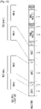
- FIG. 10 illustrates an example of a MAC PDU construction process for the NR system according to the present invention.
- a MAC at a transmitting side attaches a MAC subheader right after the end of a corresponding MAC SDU or MAC CE.
- MAC subheader interleaved with a corresponding MAC SDU or MAC CE, it is expected that MAC delivers the generated part of MAC PDU to PHY immediately after attaching a MAC subheader to a corresponding generated MAC SDU or MAC CE, even before generating whole MAC PDU, so that the PHY can start processing of the received part of MAC PDU quickly.
- a MAC at a receiving side can process the MAC PDU from the end of the MAC PDU to obtain MAC CE(s) and then process the remaining part of the MAC PDU to obtain MAC SDU(s).
- a BS e.g. gNB
- the MAC SDUs would be obtained in reverse order of the construction order of the MAC PDU, which would lead to out-of-order PDU reception in RLC.
- the out-of-order PDU reception in RLC may not be a big problem because PDCP would anyway perform reordering.
- the present invention is described using an example where a UE is a transmitting side and a BS or network is a receiving side, but the present invention is also applied in the same or similar manner even when a BS or network is a transmitting side and a UE is a receiving side, except that a UE should receive a UL grant used for MAC PDU transmission while a BS does not have to receive a DL grant used for MAC PDU transmission but can allocate it for itself.
- the UE attaches a MAC subheader at the end of a corresponding MAC SDU or MAC CE.
- the UE constructs a MAC PDU by concatenating multiple sets of 'MAC SDU + MAC subheader' and/or 'MAC CE + MAC subheader', and transmits the MAC PDU using the received UL grant.
- the MAC subheader may include a logical channel ID (LCID) field which identifies the logical channel (or RLC entity) to which the corresponding MAC SDU belongs or identifies the type of MAC CE, and a length (L) field which indicates the length of the corresponding MAC SDU or MAC CE.
- LCID logical channel ID
- L length
- the UE when the UE constructs the MAC PDU, the UE may include MAC CE(s) at the end of the MAC PDU. That is, the UE includes MAC SDU(s) first, and then includes MAC CE(s) in the MAC PDU. In a UE, some MAC CEs such as BSR or PHR need to reflect the latest UE status before transmission.
- BSR MAC CE is placed at the beginning of MAC PDU as in the LTE/LTE-A system, the MAC at the UE can only deliver the MAC PDU after a complete MAC PDU is generated, because a BSR MAC can only be generated after placing all MAC SDUs, and the PHY needs to receive MAC PDU in order, i.e., from the beginning part, for the PHY layer processing.
- Placing the MAC CE at the end of a MAC PDU enables partial MAC PDU delivery to physical layer while gives more time to reflect the latest UE status in the MAC CE.
- the placement of MAC CEs does not affect receiving process as the receiving process would start only after receiving a whole transport block.
- the receiving side especially if the receiving side is a scheduler, what is important is how fast the receiver identifies the placement of MAC CEs. It is because the receiving side could identify MAC CEs at the end of the MAC PDU even before receiving a whole transport block and perform scheduling fast based on the MAC CEs if the MAC CEs are not placed in the middle of the MAC PDU but placed at the end of the MAC CE.
- MAC CEs There are multiple types of MAC CEs defined, e.g., buffer status report (BSR) MAC CE, power headroom report (PHR) MAC CE, DRX Command MAC CE, activation/ deactivation MAC CE, etc.
- BSR buffer status report
- PHR power headroom report
- DRX Command MAC CE
- activation/ deactivation MAC CE etc.
- the placement order between MAC CEs are arbitrary, or defined by relative priority order for the LCP procedure (e.g. see the document 36.321 at section 5.4.3.1).
- the overall MAC PDU construction process in the UE may be explained as follows.
- the transmitting side e.g. UE
- a receiving side e.g. BS
- the present invention also applies to DL data transmission where the transmitting side is a BS and the receiving side is a UE.
- FIG. 11 is a block diagram illustrating elements of a transmitting device 100 and a receiving device 200 for implementing the present invention.
- the transmitting device 100 and the receiving device 200 respectively include Radio Frequency (RF) units 13 and 23 capable of transmitting and receiving radio signals carrying information, data, signals, and/or messages, memories 12 and 22 for storing information related to communication in a wireless communication system, and processors 11 and 21 operationally connected to elements such as the RF units 13 and 23 and the memories 12 and 22 to control the elements and configured to control the memories 12 and 22 and/or the RF units 13 and 23 so that a corresponding device may perform at least one of the above-described embodiments of the present invention.
- RF Radio Frequency
- the memories 12 and 22 may store programs for processing and controlling the processors 11 and 21 and may temporarily store input/output information.
- the memories 12 and 22 may be used as buffers.
- the processors 11 and 21 generally control the overall operation of various modules in the transmitting device and the receiving device. Especially, the processors 11 and 21 may perform various control functions to implement the present invention.
- the processors 11 and 21 may be referred to as controllers, microcontrollers, microprocessors, or microcomputers.
- the processors 11 and 21 may be implemented by hardware, firmware, software, or a combination thereof. In a hardware configuration, application specific integrated circuits (ASICs), digital signal processors (DSPs), digital signal processing devices (DSPDs), programmable logic devices (PLDs), or field programmable gate arrays (FPGAs) may be included in the processors 11 and 21.
- ASICs application specific integrated circuits
- DSPs digital signal processors
- DSPDs digital signal processing devices
- PLDs programmable logic devices
- FPGAs field programmable gate arrays
- firmware or software may be configured to include modules, procedures, functions, etc. performing the functions or operations of the present invention.
- Firmware or software configured to perform the present invention may be included in the processors 11 and 21 or stored in the memories 12 and 22 so as to be driven by the processors 11 and 21.
- the processor 11 of the transmitting device 100 performs predetermined coding and modulation for a signal and/or data scheduled to be transmitted to the outside by the processor 11 or a scheduler connected with the processor 11, and then transfers the coded and modulated data to the RF unit 13.
- the processor 11 converts a data stream to be transmitted into K layers through demultiplexing, channel coding, scrambling, and modulation.
- the coded data stream is also referred to as a codeword and is equivalent to a transport block which is a data block provided by a MAC layer.
- One transport block (TB) is coded into one codeword and each codeword is transmitted to the receiving device in the form of one or more layers.
- the RF unit 13 may include an oscillator.
- the RF unit 13 may include N t (where N t is a positive integer) transmit antennas.
- a signal processing process of the receiving device 200 is the reverse of the signal processing process of the transmitting device 100.
- the RF unit 23 of the receiving device 200 receives radio signals transmitted by the transmitting device 100.
- the RF unit 23 may include N r (where N r is a positive integer) receive antennas and frequency down-converts each signal received through receive antennas into a baseband signal.
- the processor 21 decodes and demodulates the radio signals received through the receive antennas and restores data that the transmitting device 100 intended to transmit.
- the RF units 13 and 23 include one or more antennas.
- An antenna performs a function for transmitting signals processed by the RF units 13 and 23 to the exterior or receiving radio signals from the exterior to transfer the radio signals to the RF units 13 and 23.
- the antenna may also be called an antenna port.
- Each antenna may correspond to one physical antenna or may be configured by a combination of more than one physical antenna element.
- the signal transmitted from each antenna cannot be further deconstructed by the receiving device 200.
- An RS transmitted through a corresponding antenna defines an antenna from the view point of the receiving device 200 and enables the receiving device 200 to derive channel estimation for the antenna, irrespective of whether the channel represents a single radio channel from one physical antenna or a composite channel from a plurality of physical antenna elements including the antenna.
- an antenna is defined such that a channel carrying a symbol of the antenna can be obtained from a channel carrying another symbol of the same antenna.
- An RF unit supporting a MIMO function of transmitting and receiving data using a plurality of antennas may be connected to two or more antennas.
- a UE operates as the transmitting device 100 in UL and as the receiving device 200 in DL.
- an eNB operates as the receiving device 200 in UL and as the transmitting device 100 in DL.
- a processor, an RF unit, and a memory included in the UE will be referred to as a UE processor, a UE RF unit, and a UE memory, respectively, and a processor, an RF unit, and a memory included in the eNB will be referred to as an eNB processor, an eNB RF unit, and an eNB memory, respectively.
- the UE processor can be configured to operate according to the present invention, or control the UE RF unit to receive or transmit signals according to the present invention.
- the eNB processor can be configured to operate according to the present invention, or control the eNB RF unit to receive or transmit signals according to the present invention.
- a processor of a transmitting device generates a medium access control (MAC) protocol data unit (PDU) according to present invention.
- the processor of the transmitting device controls the RF unit to transmit the MAC PDU.
- the processor of the transmitting device may generate or construct the MAC PDU such that the MAC PDU includes at least a MAC service data unit (SDU) and a first MAC subheader of the MAC SDU which is attached immediately after the end of the MAC SDU, or a MAC control element (CE) and a second MAC subheader of the MAC CE which is attached immediately after the end of the MAC CE.
- SDU MAC service data unit
- CE MAC control element
- the processor of the transmitting device may include, in the first MAC subheader, a logical channel identity (LCID) field which identifies a logical channel or radio link control (RLC) entity to which the MAC SDU belongs, and a length (L) field which indicates a length of the MAC SDU.
- the processor of the transmitting device may include, in the second MAC subheader, a LCID field which identifies a type of the MAC CE.
- the processor of the transmitting device may further include, in the second MAC subheader, a L field which indicates a length of the MAC CE.
- the processor of the transmitting device may include, in the second MAC subheader, the LCID after the L field.
- the processor of the transmitting device may generate or construct the MAC PDU such that the MAC PDU includes the MAC SDU and the first MAC subheader before the MAC CE and the second MAC subheader.
- the processor of the transmitting device may generate or construct the MAC PDU such that the MAC PDU includes the MAC CE and the second MAC subheader in the end of the MAC PDU.
- the transmitting device is a UE, the processor of the transmitting device generates the MAC PDU based on a UL grant received from a receiving side (e.g. BS), and controls the RF unit of the transmitting device to transmit the MAC PDU using the UL grant.
- the processor of the transmitting device may control the RF unit of the transmitting device to transmit a DL grant and control the RF unit of the transmitting device to transmit the MAC PDU using the DL grant.
- a processor of a receiving device controls a RF unit of the receiving device to receive a MAC PDU, and process the MAC PDU according to the present invention.
- the MAC PDU includes at least a MAC SDU and a first MAC subheader of the MAC SDU which is attached immediately after the end of the MAC SDU, or a MAC CE and a second MAC subheader of the MAC CE which is attached immediately after the end of the MAC CE.
- the processor of the receiving device may process the MAC PDU from the end of the MAC PDU toward the start of the MAC PDU.
- the processor of the receiving device may process the MAC SDU based on the first MAC subheader, where the first MAC subheader includes a LCID field which identifies a logical channel or RLC entity to which the MAC SDU belongs, and a L field which indicates a length of the MAC SDU.
- the processor of the receiving device may process the MAC CE based on the second MAC subheader, where the second MAC subheader includes a LCID field which identifies a type of the MAC CE.
- the second MAC subheader may or may not include a L field, which indicates a length of the MAC CE, according to the type of the MAC CE.
- the second MAC subheader may include the LCID after the L field, and the processor of the receiving device may determine the presence or absence of the L field based on the LCID of the MAC CE.
- the processor of the receiving device may process the MAC PDU on the assumption that the MAC PDU includes the MAC SDU and the first MAC subheader before the MAC CE and the second MAC subheader.
- the processor of the receiving device may process the MAC PDU on the assumption that the MAC PDU includes the MAC CE and the second MAC subheader in the end of the MAC PDU.
- the processor of the receiving device may transmit the RF unit of the receiving device to transmit a UL grant to a UE and control the RF unit of the receiving device to receive a MAC PDU using the UL grant. If the receiving device is a UE, the processor of the receiving device may control the RF unit of the receiving device to receive a DL grant and control the RF unit of the receiving device to a MAC PDU using the DL grant.
- the embodiments of the present invention are applicable to a network node (e.g., BS), a UE, or other devices in a wireless communication system.
- a network node e.g., BS
- UE User Equipment
Landscapes
- Engineering & Computer Science (AREA)
- Signal Processing (AREA)
- Computer Networks & Wireless Communication (AREA)
- Quality & Reliability (AREA)
- Mobile Radio Communication Systems (AREA)
Claims (15)
- Verfahren zum Übertragen, durch eine Übertragungsvorrichtung (100), einer Dateneinheit in einem Drahtloskommunikationssystem, wobei das Verfahren umfasst:Erzeugen, durch die Übertragungsvorrichtung (100), einer Medienzugangssteuerung-Protokolldateneinheit, MAC-PDU; undÜbertragen, durch die Übertragungsvorrichtung (100), der MAC-PDU,wobei das Verfahren dadurch gekennzeichnet ist, dass:
die MAC-PDU zumindest beinhaltet:i) eine MAC-Dienstdateneinheit, SDU, und einen ersten MAC-Subheader der MAC-SDU, der unmittelbar nach dem Ende der MAC-SDU angehängt ist, undii) ein MAC-Steuerelement, CE, und einen zweiten MAC-Subheader des MAC-CE, der unmittelbar nach dem Ende des MAC-CE angehängt ist. - Verfahren zum Empfangen, durch eine Empfangsvorrichtung (200), einer Dateneinheit in einem Drahtloskommunikationssystem, wobei das Verfahren umfasst:Empfangen, durch die Empfangsvorrichtung (200), einer Medienzugangssteuerung-Protokolldateneinheit, MAC-PDU; undVerarbeiten, durch die Empfangsvorrichtung (200), der MAC-PDU,wobei das Verfahren dadurch gekennzeichnet ist, dass:
die MAC-PDU zumindest beinhaltet:i) eine MAC-Dienstdateneinheit, SDU, und einen ersten MAC-Subheader der MAC-SDU, der unmittelbar nach dem Ende der MAC-SDU angehängt ist, undii) ein MAC-Steuerelement, CE, und einen zweiten MAC-Subheader des MAC-CE, der unmittelbar nach dem Ende des MAC-CE angehängt ist. - Verfahren nach Anspruch 2, wobei das Verarbeiten der MAC-PDU umfasst:
Verarbeiten der MAC-PDU vom Ende der MAC-PDU zu dem Start der MAC-PDU. - Verfahren nach einem der Ansprüche 1 bis 3,
wobei der erste MAC-Subheader i) ein Logikkanalidentität, LCID, -Feld, das eine Logikkanal- oder Funklinksteuerung, RLC, -Entität identifiziert, zu der die MAC-SDU gehört, und ii) ein Längen, L, -Feld, das eine Länge der MAC-SDU angibt, beinhaltet. - Verfahren nach einem der Ansprüche 1 bis 4,
wobei der zweite MAC-Subheader ein LCID-Feld beinhaltet, das einen Typ des MAC-CE identifiziert. - Verfahren nach Anspruch 5,wobei der zweite MAC-Subheader ein L-Feld beinhaltet, das eine Länge des MAC-CE angibt, undwobei der zweite MAC-Subheader das LCID-Feld nach dem L-Feld beinhaltet.
- Verfahren nach einem der Ansprüche 1 bis 6,
wobei die MAC-PDU die MAC-SDU und den ersten MAC-Subheader vor dem MAC-CE und dem zweiten MAC-Subheader beinhaltet. - Verfahren nach einem der Ansprüche 1 bis 7,
wobei die MAC-PDU das MAC-CE und den zweiten MAC-Subheader am Ende der MAC-PDU beinhaltet. - Vorrichtung (100), die zum Übertragen einer Dateneinheit in einem Drahtloskommunikationssystem konfiguriert ist, wobei die Vorrichtung (100) umfasst:einen Hochfrequenz, HF -Sendeempfänger (13);einen Prozessor (11) undeinen Speicher (12), der mindestens ein Programm speichert, das bewirkt, dass der Prozessor (11) Operationen durchführt, die umfassen:Erzeugen einer Medienzugangssteuerung-Protokolldateneinheit, MAC-PDU; undÜbertragen, über den HF-Sendeempfänger (13), der MAC-PDU,wobei die Vorrichtung (100) dadurch gekennzeichnet ist, dass:
die MAC-PDU zumindest beinhaltet:i) eine MAC-Dienstdateneinheit, SDU, und einen ersten MAC-Subheader der MAC-SDU, der unmittelbar nach dem Ende der MAC-SDU angehängt ist, undii) ein MAC-Steuerelement, CE, und einen zweiten MAC-Subheader des MAC-CE, der unmittelbar nach dem Ende des MAC-CE angehängt ist. - Vorrichtung (200), die zum Empfangen einer Dateneinheit in einem Drahtloskommunikationssystem konfiguriert ist, wobei die Vorrichtung (200) umfasst:einen Hochfrequenz, HF, -Sendeempfänger (23);einen Prozessor (21) undeinen Speicher (22), der mindestens ein Programm speichert, das bewirkt, dass der Prozessor (21) Operationen durchführt, die umfassen:Empfangen, über den HF-Sendeempfänger (23), einer Medienzugangssteuerung-Protokolldateneinheit, MAC-PDU; undVerarbeiten der MAC-PDU,wobei die Vorrichtung (200) dadurch gekennzeichnet ist, dass:
die MAC-PDU zumindest beinhalteti) eine MAC-Dienstdateneinheit, SDU, und einen ersten MAC-Subheader der MAC-SDU, der unmittelbar nach dem Ende der MAC-SDU angehängt ist, undii) ein MAC-Steuerelement, CE, und einen zweiten MAC-Subheader des MAC-CE, der unmittelbar nach dem Ende des MAC-CE angehängt ist. - Vorrichtung (200) nach Anspruch 10, wobei das Verarbeiten der MAC-PDU umfasst:
Verarbeiten der MAC-PDU vom Ende der MAC-PDU zu dem Start der MAC-PDU. - Vorrichtung (100, 200) nach einem der Ansprüche 9 bis 11,
wobei der erste MAC-Subheader i) ein Logikkanalidentitä, LCID, -Feld, das eine Logikkanal- oder Funklinksteuerung, RLC, -Entität identifiziert, zu der die MAC-SDU gehört, und ii) ein Längen, L, -Feld, das eine Länge der MAC-SDU angibt, beinhaltet. - Vorrichtung (100, 200) nach einem der Ansprüche 9 bis 12,wobei der zweite MAC-Subheader ein LCID-Feld beinhaltet, das einen Typ des MAC-CE identifiziert, undwobei der zweite MAC-Subheader ein L-Feld beinhaltet, das eine Länge des MAC-CE angibt, und der zweite MAC-Subheader das LCID-Feld nach dem L-Feld beinhaltet.
- Vorrichtung (100, 200) nach einem der Ansprüche 9 bis 13,
wobei die MAC-PDU die MAC-SDU und den ersten MAC-Subheader vor dem MAC-CE und dem zweiten MAC-Subheader beinhaltet. - Vorrichtung (100, 200) nach einem der Ansprüche 9 bis 14,
wobei die MAC-PDU das MAC-CE und den zweiten MAC-Subheader am Ende der MAC-PDU beinhaltet.
Applications Claiming Priority (2)
| Application Number | Priority Date | Filing Date | Title |
|---|---|---|---|
| US201762447881P | 2017-01-18 | 2017-01-18 | |
| PCT/KR2018/000841 WO2018135875A1 (en) | 2017-01-18 | 2018-01-18 | Method and device for transmitting data unit, and method and device for receiving data unit |
Publications (3)
| Publication Number | Publication Date |
|---|---|
| EP3571864A1 EP3571864A1 (de) | 2019-11-27 |
| EP3571864A4 EP3571864A4 (de) | 2020-10-07 |
| EP3571864B1 true EP3571864B1 (de) | 2022-09-21 |
Family
ID=62909142
Family Applications (1)
| Application Number | Title | Priority Date | Filing Date |
|---|---|---|---|
| EP18741068.3A Active EP3571864B1 (de) | 2017-01-18 | 2018-01-18 | Verfahren und vorrichtung zum senden einer dateneinheit verfahren und vorrichtung zum empfangen einer dateneinheit |
Country Status (4)
| Country | Link |
|---|---|
| US (1) | US10827509B2 (de) |
| EP (1) | EP3571864B1 (de) |
| CN (1) | CN110169120B (de) |
| WO (1) | WO2018135875A1 (de) |
Families Citing this family (8)
| Publication number | Priority date | Publication date | Assignee | Title |
|---|---|---|---|---|
| AU2018402429B2 (en) * | 2018-01-12 | 2022-11-24 | Ntt Docomo, Inc. | User terminal and radio communication method |
| US11432306B2 (en) | 2020-08-05 | 2022-08-30 | International Business Machines Corporation | Overtaking anticipation and proactive DTCH adjustment |
| US12588027B2 (en) * | 2021-02-26 | 2026-03-24 | Lg Electronics Inc. | Method and apparatus for transmitting data unit based on control uplink grant in wireless communication system |
| CN115473605A (zh) * | 2021-06-10 | 2022-12-13 | 华为技术有限公司 | 通信方法和装置 |
| CN115720125A (zh) * | 2021-08-24 | 2023-02-28 | 中国移动通信有限公司研究院 | 数据传输方法、装置、相关设备及存储介质 |
| US12058724B2 (en) * | 2022-01-20 | 2024-08-06 | Qualcomm Incorporated | PHY-layer handling of multiple relayed transport blocks by an AF/DF-relay UE in sidelink |
| WO2025208460A1 (en) * | 2024-04-03 | 2025-10-09 | Apple Inc. | Medium access control layer data transmission in ambient internet-of-things communications |
| WO2025097839A1 (en) * | 2024-07-18 | 2025-05-15 | Lenovo (Beijing) Limited | Mac pdu structure in a-iot system |
Family Cites Families (14)
| Publication number | Priority date | Publication date | Assignee | Title |
|---|---|---|---|---|
| US7206581B2 (en) * | 2003-11-05 | 2007-04-17 | Interdigital Technology Corporation | Method and apparatus for processing data blocks during soft handover |
| US8406179B2 (en) * | 2007-08-07 | 2013-03-26 | Samsung Electronics Co., Ltd. | Method and apparatus for performing random access procedure in a mobile communication system |
| US9215731B2 (en) * | 2007-12-19 | 2015-12-15 | Qualcomm Incorporated | Method and apparatus for transfer of a message on a common control channel for random access in a wireless communication network |
| EP2094038B1 (de) * | 2008-02-20 | 2015-11-04 | Amazon Technologies, Inc. | Vorrichtung und Verfahren zum Konstruieren eines Datenelements, das einen Pufferstatusbericht beinhaltet |
| CN101873577B (zh) * | 2009-04-27 | 2017-03-22 | 电信科学技术研究院 | 通知ue变更成员载波监听的方法、系统及装置 |
| KR101165642B1 (ko) * | 2009-09-02 | 2012-07-16 | 엘지전자 주식회사 | 압축 mac 헤더를 이용한 mac pdu 송수신 방법 및 장치 |
| BR112012004798B1 (pt) * | 2009-09-02 | 2021-09-21 | Apple Inc | Construção de unidade de dados de pacote de mac para sistemas sem fio |
| CN111065074B (zh) * | 2014-01-16 | 2023-06-09 | 三星电子株式会社 | 电子设备及其方法 |
| US10396942B2 (en) * | 2016-03-29 | 2019-08-27 | Samsung Electronics Co., Ltd. | Method and apparatus for transmitting and receiving data in a communication system |
| WO2017211417A1 (en) * | 2016-06-09 | 2017-12-14 | Nokia Solutions And Networks Oy | Real-time segmentation |
| WO2018053692A1 (zh) * | 2016-09-20 | 2018-03-29 | 北京小米移动软件有限公司 | 数据传输方法、装置及系统 |
| US20180124843A1 (en) * | 2016-11-01 | 2018-05-03 | Sharp Laboratories Of America, Inc. | Configurable radio link controller frame structure |
| EP3319252A1 (de) * | 2016-11-04 | 2018-05-09 | Panasonic Intellectual Property Corporation of America | Effizientes multiplexing von steuerungsinformationen in einem transportblock |
| US20180176344A1 (en) * | 2016-12-20 | 2018-06-21 | Qualcomm Incorporated | Media access control transport block design |
-
2018
- 2018-01-18 EP EP18741068.3A patent/EP3571864B1/de active Active
- 2018-01-18 CN CN201880006196.1A patent/CN110169120B/zh active Active
- 2018-01-18 US US16/349,937 patent/US10827509B2/en active Active
- 2018-01-18 WO PCT/KR2018/000841 patent/WO2018135875A1/en not_active Ceased
Also Published As
| Publication number | Publication date |
|---|---|
| EP3571864A4 (de) | 2020-10-07 |
| CN110169120A (zh) | 2019-08-23 |
| US20190342894A1 (en) | 2019-11-07 |
| EP3571864A1 (de) | 2019-11-27 |
| CN110169120B (zh) | 2023-09-19 |
| WO2018135875A1 (en) | 2018-07-26 |
| US10827509B2 (en) | 2020-11-03 |
Similar Documents
| Publication | Publication Date | Title |
|---|---|---|
| US11197187B2 (en) | Method and device for transmitting data unit | |
| EP3469829B1 (de) | Verfahren und vorrichtung zur übertragung einer dateneinheit | |
| EP3571864B1 (de) | Verfahren und vorrichtung zum senden einer dateneinheit verfahren und vorrichtung zum empfangen einer dateneinheit | |
| EP3619910B1 (de) | Verfahren und vorrichtung zur übertragung einer dateneinheit | |
| US20200205224A1 (en) | Method and device for receiving data unit | |
| EP4117387A1 (de) | Ressourcenverwaltung in einem drahtloskommunikationssystem | |
| US20180014284A1 (en) | Method and user equipment for receiving downlink signal | |
| EP3679757B1 (de) | Verfahren und benutzervorrichtung zur übertragung von uplink-signalen | |
| EP3539317B1 (de) | Verfahren und vorrichtung zum senden einer dateneinheit, und verfahren und vorrichtung zum empfangen einer dateneinheit | |
| US11197313B2 (en) | Method and user equipment for transmitting data unit | |
| US11082889B2 (en) | Method and device for receiving data unit | |
| US11115837B2 (en) | Method and device for transmitting data unit, and method and device for receiving data unit | |
| US20190306918A1 (en) | Method for handling sdap entity in wireless communication system and apparatus therefor | |
| US11252605B2 (en) | Method and device for transmitting data unit | |
| EP3777311B1 (de) | Verfahren und vorrichtung zur übertragung von signalen durch eine tm-rlc-instanz eines übertragungsendes in einem drahtlosen kommunikationssystem | |
| HK40011962A (en) | Method and device for transmitting data unit |
Legal Events
| Date | Code | Title | Description |
|---|---|---|---|
| STAA | Information on the status of an ep patent application or granted ep patent |
Free format text: STATUS: THE INTERNATIONAL PUBLICATION HAS BEEN MADE |
|
| PUAI | Public reference made under article 153(3) epc to a published international application that has entered the european phase |
Free format text: ORIGINAL CODE: 0009012 |
|
| STAA | Information on the status of an ep patent application or granted ep patent |
Free format text: STATUS: REQUEST FOR EXAMINATION WAS MADE |
|
| 17P | Request for examination filed |
Effective date: 20190614 |
|
| AK | Designated contracting states |
Kind code of ref document: A1 Designated state(s): AL AT BE BG CH CY CZ DE DK EE ES FI FR GB GR HR HU IE IS IT LI LT LU LV MC MK MT NL NO PL PT RO RS SE SI SK SM TR |
|
| AX | Request for extension of the european patent |
Extension state: BA ME |
|
| DAV | Request for validation of the european patent (deleted) | ||
| DAX | Request for extension of the european patent (deleted) | ||
| A4 | Supplementary search report drawn up and despatched |
Effective date: 20200908 |
|
| RIC1 | Information provided on ipc code assigned before grant |
Ipc: H04W 28/06 20090101AFI20200902BHEP |
|
| GRAP | Despatch of communication of intention to grant a patent |
Free format text: ORIGINAL CODE: EPIDOSNIGR1 |
|
| STAA | Information on the status of an ep patent application or granted ep patent |
Free format text: STATUS: GRANT OF PATENT IS INTENDED |
|
| INTG | Intention to grant announced |
Effective date: 20220426 |
|
| GRAS | Grant fee paid |
Free format text: ORIGINAL CODE: EPIDOSNIGR3 |
|
| GRAA | (expected) grant |
Free format text: ORIGINAL CODE: 0009210 |
|
| STAA | Information on the status of an ep patent application or granted ep patent |
Free format text: STATUS: THE PATENT HAS BEEN GRANTED |
|
| AK | Designated contracting states |
Kind code of ref document: B1 Designated state(s): AL AT BE BG CH CY CZ DE DK EE ES FI FR GB GR HR HU IE IS IT LI LT LU LV MC MK MT NL NO PL PT RO RS SE SI SK SM TR |
|
| REG | Reference to a national code |
Ref country code: GB Ref legal event code: FG4D |
|
| REG | Reference to a national code |
Ref country code: CH Ref legal event code: EP |
|
| REG | Reference to a national code |
Ref country code: DE Ref legal event code: R096 Ref document number: 602018040904 Country of ref document: DE |
|
| REG | Reference to a national code |
Ref country code: IE Ref legal event code: FG4D |
|
| REG | Reference to a national code |
Ref country code: AT Ref legal event code: REF Ref document number: 1520576 Country of ref document: AT Kind code of ref document: T Effective date: 20221015 |
|
| REG | Reference to a national code |
Ref country code: LT Ref legal event code: MG9D |
|
| REG | Reference to a national code |
Ref country code: NL Ref legal event code: MP Effective date: 20220921 |
|
| PG25 | Lapsed in a contracting state [announced via postgrant information from national office to epo] |
Ref country code: SE Free format text: LAPSE BECAUSE OF FAILURE TO SUBMIT A TRANSLATION OF THE DESCRIPTION OR TO PAY THE FEE WITHIN THE PRESCRIBED TIME-LIMIT Effective date: 20220921 Ref country code: RS Free format text: LAPSE BECAUSE OF FAILURE TO SUBMIT A TRANSLATION OF THE DESCRIPTION OR TO PAY THE FEE WITHIN THE PRESCRIBED TIME-LIMIT Effective date: 20220921 Ref country code: NO Free format text: LAPSE BECAUSE OF FAILURE TO SUBMIT A TRANSLATION OF THE DESCRIPTION OR TO PAY THE FEE WITHIN THE PRESCRIBED TIME-LIMIT Effective date: 20221221 Ref country code: LV Free format text: LAPSE BECAUSE OF FAILURE TO SUBMIT A TRANSLATION OF THE DESCRIPTION OR TO PAY THE FEE WITHIN THE PRESCRIBED TIME-LIMIT Effective date: 20220921 Ref country code: LT Free format text: LAPSE BECAUSE OF FAILURE TO SUBMIT A TRANSLATION OF THE DESCRIPTION OR TO PAY THE FEE WITHIN THE PRESCRIBED TIME-LIMIT Effective date: 20220921 Ref country code: FI Free format text: LAPSE BECAUSE OF FAILURE TO SUBMIT A TRANSLATION OF THE DESCRIPTION OR TO PAY THE FEE WITHIN THE PRESCRIBED TIME-LIMIT Effective date: 20220921 |
|
| REG | Reference to a national code |
Ref country code: AT Ref legal event code: MK05 Ref document number: 1520576 Country of ref document: AT Kind code of ref document: T Effective date: 20220921 |
|
| PG25 | Lapsed in a contracting state [announced via postgrant information from national office to epo] |
Ref country code: HR Free format text: LAPSE BECAUSE OF FAILURE TO SUBMIT A TRANSLATION OF THE DESCRIPTION OR TO PAY THE FEE WITHIN THE PRESCRIBED TIME-LIMIT Effective date: 20220921 Ref country code: GR Free format text: LAPSE BECAUSE OF FAILURE TO SUBMIT A TRANSLATION OF THE DESCRIPTION OR TO PAY THE FEE WITHIN THE PRESCRIBED TIME-LIMIT Effective date: 20221222 |
|
| PG25 | Lapsed in a contracting state [announced via postgrant information from national office to epo] |
Ref country code: SM Free format text: LAPSE BECAUSE OF FAILURE TO SUBMIT A TRANSLATION OF THE DESCRIPTION OR TO PAY THE FEE WITHIN THE PRESCRIBED TIME-LIMIT Effective date: 20220921 Ref country code: RO Free format text: LAPSE BECAUSE OF FAILURE TO SUBMIT A TRANSLATION OF THE DESCRIPTION OR TO PAY THE FEE WITHIN THE PRESCRIBED TIME-LIMIT Effective date: 20220921 Ref country code: PT Free format text: LAPSE BECAUSE OF FAILURE TO SUBMIT A TRANSLATION OF THE DESCRIPTION OR TO PAY THE FEE WITHIN THE PRESCRIBED TIME-LIMIT Effective date: 20230123 Ref country code: ES Free format text: LAPSE BECAUSE OF FAILURE TO SUBMIT A TRANSLATION OF THE DESCRIPTION OR TO PAY THE FEE WITHIN THE PRESCRIBED TIME-LIMIT Effective date: 20220921 Ref country code: CZ Free format text: LAPSE BECAUSE OF FAILURE TO SUBMIT A TRANSLATION OF THE DESCRIPTION OR TO PAY THE FEE WITHIN THE PRESCRIBED TIME-LIMIT Effective date: 20220921 Ref country code: AT Free format text: LAPSE BECAUSE OF FAILURE TO SUBMIT A TRANSLATION OF THE DESCRIPTION OR TO PAY THE FEE WITHIN THE PRESCRIBED TIME-LIMIT Effective date: 20220921 |
|
| PG25 | Lapsed in a contracting state [announced via postgrant information from national office to epo] |
Ref country code: SK Free format text: LAPSE BECAUSE OF FAILURE TO SUBMIT A TRANSLATION OF THE DESCRIPTION OR TO PAY THE FEE WITHIN THE PRESCRIBED TIME-LIMIT Effective date: 20220921 Ref country code: PL Free format text: LAPSE BECAUSE OF FAILURE TO SUBMIT A TRANSLATION OF THE DESCRIPTION OR TO PAY THE FEE WITHIN THE PRESCRIBED TIME-LIMIT Effective date: 20220921 Ref country code: IS Free format text: LAPSE BECAUSE OF FAILURE TO SUBMIT A TRANSLATION OF THE DESCRIPTION OR TO PAY THE FEE WITHIN THE PRESCRIBED TIME-LIMIT Effective date: 20230121 Ref country code: EE Free format text: LAPSE BECAUSE OF FAILURE TO SUBMIT A TRANSLATION OF THE DESCRIPTION OR TO PAY THE FEE WITHIN THE PRESCRIBED TIME-LIMIT Effective date: 20220921 |
|
| REG | Reference to a national code |
Ref country code: DE Ref legal event code: R097 Ref document number: 602018040904 Country of ref document: DE |
|
| PG25 | Lapsed in a contracting state [announced via postgrant information from national office to epo] |
Ref country code: NL Free format text: LAPSE BECAUSE OF FAILURE TO SUBMIT A TRANSLATION OF THE DESCRIPTION OR TO PAY THE FEE WITHIN THE PRESCRIBED TIME-LIMIT Effective date: 20220921 Ref country code: AL Free format text: LAPSE BECAUSE OF FAILURE TO SUBMIT A TRANSLATION OF THE DESCRIPTION OR TO PAY THE FEE WITHIN THE PRESCRIBED TIME-LIMIT Effective date: 20220921 |
|
| PLBE | No opposition filed within time limit |
Free format text: ORIGINAL CODE: 0009261 |
|
| STAA | Information on the status of an ep patent application or granted ep patent |
Free format text: STATUS: NO OPPOSITION FILED WITHIN TIME LIMIT |
|
| PG25 | Lapsed in a contracting state [announced via postgrant information from national office to epo] |
Ref country code: DK Free format text: LAPSE BECAUSE OF FAILURE TO SUBMIT A TRANSLATION OF THE DESCRIPTION OR TO PAY THE FEE WITHIN THE PRESCRIBED TIME-LIMIT Effective date: 20220921 |
|
| 26N | No opposition filed |
Effective date: 20230622 |
|
| PG25 | Lapsed in a contracting state [announced via postgrant information from national office to epo] |
Ref country code: SI Free format text: LAPSE BECAUSE OF FAILURE TO SUBMIT A TRANSLATION OF THE DESCRIPTION OR TO PAY THE FEE WITHIN THE PRESCRIBED TIME-LIMIT Effective date: 20220921 |
|
| REG | Reference to a national code |
Ref country code: CH Ref legal event code: PL |
|
| PG25 | Lapsed in a contracting state [announced via postgrant information from national office to epo] |
Ref country code: LU Free format text: LAPSE BECAUSE OF NON-PAYMENT OF DUE FEES Effective date: 20230118 |
|
| REG | Reference to a national code |
Ref country code: BE Ref legal event code: MM Effective date: 20230131 |
|
| PG25 | Lapsed in a contracting state [announced via postgrant information from national office to epo] |
Ref country code: LI Free format text: LAPSE BECAUSE OF NON-PAYMENT OF DUE FEES Effective date: 20230131 Ref country code: CH Free format text: LAPSE BECAUSE OF NON-PAYMENT OF DUE FEES Effective date: 20230131 |
|
| PG25 | Lapsed in a contracting state [announced via postgrant information from national office to epo] |
Ref country code: FR Free format text: LAPSE BECAUSE OF NON-PAYMENT OF DUE FEES Effective date: 20230131 Ref country code: BE Free format text: LAPSE BECAUSE OF NON-PAYMENT OF DUE FEES Effective date: 20230131 |
|
| PG25 | Lapsed in a contracting state [announced via postgrant information from national office to epo] |
Ref country code: IE Free format text: LAPSE BECAUSE OF NON-PAYMENT OF DUE FEES Effective date: 20230118 |
|
| PG25 | Lapsed in a contracting state [announced via postgrant information from national office to epo] |
Ref country code: IT Free format text: LAPSE BECAUSE OF FAILURE TO SUBMIT A TRANSLATION OF THE DESCRIPTION OR TO PAY THE FEE WITHIN THE PRESCRIBED TIME-LIMIT Effective date: 20220921 |
|
| PG25 | Lapsed in a contracting state [announced via postgrant information from national office to epo] |
Ref country code: MC Free format text: LAPSE BECAUSE OF FAILURE TO SUBMIT A TRANSLATION OF THE DESCRIPTION OR TO PAY THE FEE WITHIN THE PRESCRIBED TIME-LIMIT Effective date: 20220921 |
|
| PG25 | Lapsed in a contracting state [announced via postgrant information from national office to epo] |
Ref country code: MC Free format text: LAPSE BECAUSE OF FAILURE TO SUBMIT A TRANSLATION OF THE DESCRIPTION OR TO PAY THE FEE WITHIN THE PRESCRIBED TIME-LIMIT Effective date: 20220921 |
|
| PG25 | Lapsed in a contracting state [announced via postgrant information from national office to epo] |
Ref country code: BG Free format text: LAPSE BECAUSE OF FAILURE TO SUBMIT A TRANSLATION OF THE DESCRIPTION OR TO PAY THE FEE WITHIN THE PRESCRIBED TIME-LIMIT Effective date: 20220921 |
|
| PG25 | Lapsed in a contracting state [announced via postgrant information from national office to epo] |
Ref country code: BG Free format text: LAPSE BECAUSE OF FAILURE TO SUBMIT A TRANSLATION OF THE DESCRIPTION OR TO PAY THE FEE WITHIN THE PRESCRIBED TIME-LIMIT Effective date: 20220921 |
|
| PG25 | Lapsed in a contracting state [announced via postgrant information from national office to epo] |
Ref country code: CY Free format text: LAPSE BECAUSE OF FAILURE TO SUBMIT A TRANSLATION OF THE DESCRIPTION OR TO PAY THE FEE WITHIN THE PRESCRIBED TIME-LIMIT; INVALID AB INITIO Effective date: 20180118 |
|
| PG25 | Lapsed in a contracting state [announced via postgrant information from national office to epo] |
Ref country code: HU Free format text: LAPSE BECAUSE OF FAILURE TO SUBMIT A TRANSLATION OF THE DESCRIPTION OR TO PAY THE FEE WITHIN THE PRESCRIBED TIME-LIMIT; INVALID AB INITIO Effective date: 20180118 |
|
| PG25 | Lapsed in a contracting state [announced via postgrant information from national office to epo] |
Ref country code: TR Free format text: LAPSE BECAUSE OF FAILURE TO SUBMIT A TRANSLATION OF THE DESCRIPTION OR TO PAY THE FEE WITHIN THE PRESCRIBED TIME-LIMIT Effective date: 20220921 |
|
| PGFP | Annual fee paid to national office [announced via postgrant information from national office to epo] |
Ref country code: GB Payment date: 20251208 Year of fee payment: 9 |
|
| PGFP | Annual fee paid to national office [announced via postgrant information from national office to epo] |
Ref country code: DE Payment date: 20251208 Year of fee payment: 9 |