EP3572193A1 - Système et procédé de commande d'un bras robotique - Google Patents
Système et procédé de commande d'un bras robotique Download PDFInfo
- Publication number
- EP3572193A1 EP3572193A1 EP19175355.7A EP19175355A EP3572193A1 EP 3572193 A1 EP3572193 A1 EP 3572193A1 EP 19175355 A EP19175355 A EP 19175355A EP 3572193 A1 EP3572193 A1 EP 3572193A1
- Authority
- EP
- European Patent Office
- Prior art keywords
- robotic arm
- environment
- path
- determining
- orientation
- Prior art date
- Legal status (The legal status is an assumption and is not a legal conclusion. Google has not performed a legal analysis and makes no representation as to the accuracy of the status listed.)
- Ceased
Links
Images





Classifications
-
- B—PERFORMING OPERATIONS; TRANSPORTING
- B23—MACHINE TOOLS; METAL-WORKING NOT OTHERWISE PROVIDED FOR
- B23P—METAL-WORKING NOT OTHERWISE PROVIDED FOR; COMBINED OPERATIONS; UNIVERSAL MACHINE TOOLS
- B23P6/00—Restoring or reconditioning objects
- B23P6/002—Repairing turbine components, e.g. moving or stationary blades, rotors
-
- B—PERFORMING OPERATIONS; TRANSPORTING
- B25—HAND TOOLS; PORTABLE POWER-DRIVEN TOOLS; MANIPULATORS
- B25J—MANIPULATORS; CHAMBERS PROVIDED WITH MANIPULATION DEVICES
- B25J18/00—Arms
- B25J18/02—Arms extensible
-
- B—PERFORMING OPERATIONS; TRANSPORTING
- B25—HAND TOOLS; PORTABLE POWER-DRIVEN TOOLS; MANIPULATORS
- B25J—MANIPULATORS; CHAMBERS PROVIDED WITH MANIPULATION DEVICES
- B25J9/00—Program-controlled manipulators
- B25J9/16—Program controls
- B25J9/1602—Program controls characterised by the control system, structure, architecture
-
- B—PERFORMING OPERATIONS; TRANSPORTING
- B25—HAND TOOLS; PORTABLE POWER-DRIVEN TOOLS; MANIPULATORS
- B25J—MANIPULATORS; CHAMBERS PROVIDED WITH MANIPULATION DEVICES
- B25J9/00—Program-controlled manipulators
- B25J9/16—Program controls
- B25J9/1656—Program controls characterised by programming, planning systems for manipulators
- B25J9/1664—Program controls characterised by programming, planning systems for manipulators characterised by motion, path, trajectory planning
-
- B—PERFORMING OPERATIONS; TRANSPORTING
- B25—HAND TOOLS; PORTABLE POWER-DRIVEN TOOLS; MANIPULATORS
- B25J—MANIPULATORS; CHAMBERS PROVIDED WITH MANIPULATION DEVICES
- B25J9/00—Program-controlled manipulators
- B25J9/16—Program controls
- B25J9/1656—Program controls characterised by programming, planning systems for manipulators
- B25J9/1664—Program controls characterised by programming, planning systems for manipulators characterised by motion, path, trajectory planning
- B25J9/1666—Avoiding collision or forbidden zones
-
- B—PERFORMING OPERATIONS; TRANSPORTING
- B25—HAND TOOLS; PORTABLE POWER-DRIVEN TOOLS; MANIPULATORS
- B25J—MANIPULATORS; CHAMBERS PROVIDED WITH MANIPULATION DEVICES
- B25J9/00—Program-controlled manipulators
- B25J9/16—Program controls
- B25J9/1679—Program controls characterised by the tasks executed
-
- G—PHYSICS
- G05—CONTROLLING; REGULATING
- G05B—CONTROL OR REGULATING SYSTEMS IN GENERAL; FUNCTIONAL ELEMENTS OF SUCH SYSTEMS; MONITORING OR TESTING ARRANGEMENTS FOR SUCH SYSTEMS OR ELEMENTS
- G05B2219/00—Program-control systems
- G05B2219/30—Nc systems
- G05B2219/40—Robotics, robotics mapping to robotics vision
- G05B2219/40234—Snake arm, flexi-digit robotic manipulator, a hand at each end
-
- G—PHYSICS
- G05—CONTROLLING; REGULATING
- G05B—CONTROL OR REGULATING SYSTEMS IN GENERAL; FUNCTIONAL ELEMENTS OF SUCH SYSTEMS; MONITORING OR TESTING ARRANGEMENTS FOR SUCH SYSTEMS OR ELEMENTS
- G05B2219/00—Program-control systems
- G05B2219/30—Nc systems
- G05B2219/40—Robotics, robotics mapping to robotics vision
- G05B2219/40371—Control trajectory to avoid joint limit as well as obstacle collision
-
- G—PHYSICS
- G05—CONTROLLING; REGULATING
- G05B—CONTROL OR REGULATING SYSTEMS IN GENERAL; FUNCTIONAL ELEMENTS OF SUCH SYSTEMS; MONITORING OR TESTING ARRANGEMENTS FOR SUCH SYSTEMS OR ELEMENTS
- G05B2219/00—Program-control systems
- G05B2219/30—Nc systems
- G05B2219/40—Robotics, robotics mapping to robotics vision
- G05B2219/40476—Collision, planning for collision free path
-
- G—PHYSICS
- G05—CONTROLLING; REGULATING
- G05B—CONTROL OR REGULATING SYSTEMS IN GENERAL; FUNCTIONAL ELEMENTS OF SUCH SYSTEMS; MONITORING OR TESTING ARRANGEMENTS FOR SUCH SYSTEMS OR ELEMENTS
- G05B2219/00—Program-control systems
- G05B2219/30—Nc systems
- G05B2219/40—Robotics, robotics mapping to robotics vision
- G05B2219/40518—Motion and task planning
-
- G—PHYSICS
- G05—CONTROLLING; REGULATING
- G05B—CONTROL OR REGULATING SYSTEMS IN GENERAL; FUNCTIONAL ELEMENTS OF SUCH SYSTEMS; MONITORING OR TESTING ARRANGEMENTS FOR SUCH SYSTEMS OR ELEMENTS
- G05B2219/00—Program-control systems
- G05B2219/30—Nc systems
- G05B2219/40—Robotics, robotics mapping to robotics vision
- G05B2219/40519—Motion, trajectory planning
-
- Y—GENERAL TAGGING OF NEW TECHNOLOGICAL DEVELOPMENTS; GENERAL TAGGING OF CROSS-SECTIONAL TECHNOLOGIES SPANNING OVER SEVERAL SECTIONS OF THE IPC; TECHNICAL SUBJECTS COVERED BY FORMER USPC CROSS-REFERENCE ART COLLECTIONS [XRACs] AND DIGESTS
- Y10—TECHNICAL SUBJECTS COVERED BY FORMER USPC
- Y10S—TECHNICAL SUBJECTS COVERED BY FORMER USPC CROSS-REFERENCE ART COLLECTIONS [XRACs] AND DIGESTS
- Y10S901/00—Robots
- Y10S901/02—Arm motion controller
- Y10S901/09—Closed loop, sensor feedback controls arm movement
Definitions
- the present subject matter relates generally to a system and method for controlling a robotic arm through an environment.
- At least certain gas turbine engines include, in serial flow arrangement, a compressor section including a low pressure compressor and a high-pressure compressor for compressing air flowing through the engine, a combustor for mixing fuel with the compressed air such that the mixture may be ignited, and a turbine section including a high pressure turbine and a low pressure turbine for providing power to the compressor section.
- the gas turbine engine Throughout the life of the gas turbine engine, it generally becomes necessary to inspect and/or repair one or more components of the gas turbine engine.
- the gas turbine engine must be uninstalled from a wing of an aircraft with which it is utilized and/or disassembled to expose the part needing inspection and/or repair.
- such may be a relatively costly and time consuming process.
- robotic arms may be used to inspect and/or repair certain components within the gas turbine engine without necessitating an un-installation or disassembly of the gas turbine engine.
- these robotic arms determine the path along which it travels incrementally as it passes through an environment, such as the gas turbine engine.
- the inventors of the present disclosure have discovered that such a control methodology may result in a difficulty in achieving certain task-based processes. Accordingly, an improved method for controlling a robotic arm would be useful.
- a method for controlling a robotic arm assembly through an environment includes a robotic arm, a base, and a utility member, the robotic arm extending between a root end attached to the base and a distal end including the utility member.
- the method includes: determining a position of the base, the root end, or both relative to the environment; determining a task position and orientation for the utility member within the environment; determining a three-dimensional constraint of the environment; and determining a path for the robotic arm through the environment based on each of the position of the base, the root end, or both relative to the environment, the task position and orientation for the utility member within the environment, and the three-dimensional constraint of the environment.
- the method further includes directing the robotic arm through the environment along the path determined for the robotic arm through the environment.
- directing the robotic arm through the environment along the path determined for the robotic arm includes directing the robotic arm through the environment along the path using a tip following sequence.
- the environment is a gas turbine engine, and wherein determining the three-dimensional constraint of the environment includes determining the three-dimensional constraint the environment using a three-dimensional electronic representation or model of the gas turbine engine.
- the method further includes determining a set of operability limitations of the robotic arm, and wherein determining the path for the robotic arm through the environment includes determining the path for the robotic arm through the environment further based on the set of operability limitations of the robotic arm.
- determining the set of operability limitations of the robotic arm includes determining a set of joint limitations of the robotic arm, a set of geometric limitations for a plurality of segments of the robotic arm, or both.
- the determined task position and orientation for the utility member is a first task position and orientation for the utility member, wherein the path for the robotic arm through the environment is a first path for the robotic arm through the environment.
- the method may further include determining a second task position and orientation for the utility member within the environment; and determining a second path for the robotic arm through the environment based on each of the position of the base, the root end, or both relative to the environment, the second task position and orientation for the utility member within the environment, and the three-dimensional constraint of the environment.
- the method may further include determining a transitional movement of the robotic arm from the first path to the second path.
- determining the transitional movement of the robotic arm from the first path to the second path includes interpolating one or more transitional paths between the first path and the second path.
- the first task position and orientation for utility member within the environment is a starting point of a task
- the second task position and orientation for the utility member within the environment is an ending point of the task
- the path for the robotic arm through the environment includes a plurality of sequential vectors for the robotic arm to follow.
- a computer implemented method for controlling a robotic arm assembly through a gas turbine engine includes a robotic arm, a base, and a utility member, the robotic arm extending between a root end attached to the base and a distal end including the utility member.
- the method includes: determining, by one or more computing devices, a position of the base, the root end, or both relative to the gas turbine engine; determining, by the one or more computing devices, a task position and orientation for the utility member within the gas turbine engine; determining, by the one or more computing devices, a three-dimensional constraint of the gas turbine engine; and determining, by the one or more computing devices, a path for the robotic arm through the gas turbine engine based on each of the position of the base, the root end, or both relative to the gas turbine engine, the task position and orientation for the utility member within the gas turbine engine, and the three-dimensional constraint of the gas turbine engine.
- the method may further include directing, by the one or more computing devices, the robotic arm through the gas turbine engine along the path determined for the robotic arm through the gas turbine engine.
- determining, by the one or more computing devices, the three-dimensional constraint of the gas turbine engine includes determining, by the one or more computing devices, the three-dimensional constraint the gas turbine engine using a CAD file of the gas turbine engine.
- the method may further include determining, by the one or more computing devices, a set of operability limitations of the robotic arm, and wherein determining, by the one or more computing devices, the path for the robotic arm through the gas turbine engine includes determining, by the one or more computing devices, the path for the robotic arm through the gas turbine engine further based on the set of operability limitations of the robotic arm.
- determining, by the one or more computing devices, the set of operability limitations of the robotic arm includes determining, by the one or more computing devices, a set of joint limitations of the robotic arm, a set of geometric limitations for a plurality of segments of the robotic arm, or both.
- the determined task position and orientation for the utility member is a first task position and orientation for the utility member, wherein the path for the robotic arm through the environment is a first path for the robotic arm through the gas turbine engine.
- the method may further include: determining, by the one or more computing devices, a second task position and orientation for the utility member within the gas turbine engine; and determining, by the one or more computing devices, a second path for the robotic arm through the gas turbine engine based on each of the position of the base, the root end, or both relative to the gas turbine engine, the second task position and orientation for the utility member within the gas turbine engine, and the three-dimensional constraint of the gas turbine engine.
- the method further includes determining, by the one or more computing devices, a transitional movement of the robotic arm from the first path to the second path.
- a robotic arm assembly in another exemplary embodiment of the present disclosure, includes a base; a utility member; a robotic arm extending between a root end and a distal end, the root end of the robotic arm coupled to the base and the distal end including the utility member; and a controller operable with the base, the robotic arm, or both.
- the controller includes one or more processors and memory, the memory storing data, the data including instructions that when executed by the one or more processors cause the robotic arm assembly to perform functions.
- the functions include: determining a position of the base, the root end, or both relative to an environment; determining a task position and orientation for the utility member within the environment; determining a three-dimensional constraint of the environment; and determining a path for the robotic arm through the environment based on each of the position of the base, the root end, or both relative to the environment, the task position and orientation for the utility member within the environment, and the three-dimensional constraint of the environment.
- the instructions further include directing the robotic arm through the environment along the path determined for the robotic arm through the environment.
- first, second, and third may be used interchangeably to distinguish one component from another and are not intended to signify location or importance of the individual components.
- forward and aft refer to relative positions within a gas turbine engine or vehicle, and refer to the normal operational attitude of the gas turbine engine or vehicle.
- forward refers to a position closer to an engine inlet and aft refers to a position closer to an engine nozzle or exhaust.
- upstream and downstream refer to the relative direction with respect to fluid flow in a fluid pathway.
- upstream refers to the direction from which the fluid flows
- downstream refers to the direction to which the fluid flows.
- Coupled refers to both direct coupling, fixing, or attaching, as well as indirect coupling, fixing, or attaching through one or more intermediate components or features, unless otherwise specified herein.
- Approximating language is applied to modify any quantitative representation that could permissibly vary without resulting in a change in the basic function to which it is related. Accordingly, a value modified by a term or terms, such as “about”, “approximately”, and “substantially”, are not to be limited to the precise value specified. In at least some instances, the approximating language may correspond to the precision of an instrument for measuring the value, or the precision of the methods or machines for constructing or manufacturing the components and/or systems. For example, the approximating language may refer to being within a 10 percent margin.
- Fig. 1 is a schematic cross-sectional view of a gas turbine engine in accordance with an exemplary embodiment of the present disclosure. More particularly, for the embodiment of Fig. 1 , the gas turbine engine is a high-bypass turbofan jet engine 10, referred to herein as "turbofan engine 10." As shown in Fig. 1 , the turbofan engine 10 defines an axial direction A (extending parallel to a longitudinal centerline 12 provided for reference) and a radial direction R. The turbofan engine 10 also defines a circumferential direction C (see, e.g., Fig. 2 ) extending circumferentially about the axial direction A. In general, the turbofan 10 includes a fan section 14 and a turbomachine 16 disposed downstream from the fan section 14.
- the exemplary turbomachine 16 depicted is generally enclosed within a substantially tubular outer casing 18 that defines an annular inlet 20 and an annular exhaust 21.
- the outer casing 18 encases, in serial flow relationship, a compressor section including a booster or low pressure (LP) compressor 22 and a high pressure (HP) compressor 24; a combustion section 26; a turbine section including a high pressure (HP) turbine 28 and a low pressure (LP) turbine 30; and a jet exhaust nozzle section 32.
- a high pressure (HP) shaft or spool 34 drivingly connects the HP turbine 28 to the HP compressor 24.
- a low pressure (LP) shaft or spool 36 drivingly connects the LP turbine 30 to the LP compressor 22.
- the compressor section, combustion section 26, turbine section, and nozzle section 32 together define a core air flowpath 37 therethrough.
- the fan section 14 includes a fixed pitch fan 38 having a plurality of fan blades 40.
- the fan blades 40 are each attached to a disk 42, with the fan blades 40 and disk 42 together rotatable about the longitudinal axis 12 by the LP shaft 36.
- the turbofan engine 10 is a direct drive turbofan engine, such that the LP shaft 36 drives the fan 38 of the fan section 14 directly, without use of a reduction gearbox.
- the fan 38 may instead be a variable pitch fan, and the turbofan engine 10 may include a reduction gearbox, in which case the LP shaft 36 may drive the fan 38 of the fan section 14 across the gearbox.
- the disk 42 is covered by rotatable front hub 48 aerodynamically contoured to promote an airflow through the plurality of fan blades 40.
- the exemplary turbofan engine 10 includes an annular nacelle assembly 50 that circumferentially surrounds the fan 38 and/or at least a portion of the turbomachine 16.
- the nacelle assembly 50 is supported relative to the turbomachine 16 by a plurality of circumferentially-spaced outlet guide vanes 52.
- a downstream section 54 of the nacelle assembly 50 extends over an outer portion of the casing 18 so as to define a bypass airflow passage 56 therebetween.
- the ratio between a first portion of air through the bypass airflow passage 56 and a second portion of air through the inlet 20 of the turbomachine 16, and through the core air flowpath 37, is commonly known as a bypass ratio.
- turbofan engine 10 depicted in Fig. 1 is by way of example only, and that in other exemplary embodiments, the turbofan engine 10 may have any other suitable configuration, including, for example, any other suitable number of shafts or spools, turbines, compressors, etc. Additionally, or alternatively, in other exemplary embodiments, any other suitable turbine engine may be provided.
- the turbine engine may not be a turbofan engine, and instead may be configured as a turboshaft engine, a turboprop engine, turbojet engine, etc.
- Fig. 2 provides a plan view of a section of the LP compressor 22 of the exemplary turbomachine 16 of Fig. 1 along the axial and circumferential directions A, C
- Fig. 3 provides a schematic view of a portion of the LP compressor 22 of the exemplary turbomachine 16 of Fig. 1 along the axial and radial directions A, R.
- the LP compressor 22 includes a plurality of stages of LP compressor rotor blades 60, which are configured to rotate about the axial direction A of the turbofan engine 10 (i.e., along the circumferential direction C) during operation of the turbofan engine 10. More specifically, for the embodiment depicted in Fig. 2 , the LP compressor 22 includes a first stage 62 of LP compressor rotor blades 60 and a second stage 64 of LP compressor rotor blades 60. The LP compressor 22 further includes a plurality of stages of LP compressor stator vanes 66, and more specifically, a first stage 68 of LP compressor stator vanes 66 and a second stage 70 of LP compressor stator vanes 66.
- Each of the plurality of LP compressor stator vanes 66 generally remain stationary during operation of the turbofan engine 10.
- a three-dimensional path 74 must be traversed through the first and second stages 62, 64 of LP compressor rotor blades 60 and the first stage of LP compressor stator vanes 66.
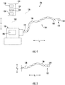
- the robot arm assembly 100 generally defines a vertical direction V, a longitudinal direction L1, and a lateral direction L2 (see Fig. 5 ), and further generally includes a base 102, a robotic arm 104, and a utility member 122.
- the base 102 includes one or more motors 106 operable with the robotic arm 104 to actuate the robotic arm 104.
- the robotic arm 104 includes a plurality of segments 108 (also referred to as "links") sequentially arranged and extending from the base 102 between a root end 110 and a distal end 112, e.g., generally along the longitudinal direction L1 of the robot arm assembly 100 for the embodiment shown.
- the robotic arm 104 is, for the embodiment depicted, coupled to the base 102 at its root end 110.
- each segment 108 may be movable relative to a forward-adjacent segment 108 (i.e., a segment 108 immediately forward of the segment 108/towards the distal end 112) and aft-adjacent segment 108 (i.e., a segment 108 immediately aft of the segment 108/towards the root end 110) along at least two degrees of operation, as is depicted to form the two-dimensional shape of the robotic arm 104 in Fig. 4 .
- each segment 108 may be movable up or down relative to the forward-adjacent and aft-adjacent segments 108 along the vertical direction V of the robot arm assembly 100.
- each segment 108 is further movable relative to a respective forward-adjacent and aft-adjacent segment 108 along at least four degrees of operation.
- each segment 108 may also be movable along a lateral direction L2 relative to the forward-adjacent and aft-adjacent segments 108.
- the robotic arm 104 may generally be movable to form various three-dimensional shapes.
- the one or more motors 106 of the base 102 may generally pull on various wires (not shown) extending through the robotic arm 104 and terminating at individual segments 108 of the robotic arm 104. By pulling on these various wires, the one or more motors 106 of the base 102 may control a movement of the segments 108 of the robotic arm 104.
- any other suitable configuration may be provided for controlling the robotic arm 104.
- the robotic arm 104 defines a set of operability limitations.
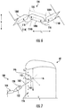
- a close-up view of a segment 108 of the exemplary robotic arm 104 of Figs. 4 and 5 is provided.
- Fig. 6 provides a close-up view of a first segment 108A of the robotic arm 104, along with a second segment 108 B located immediately forward of the first segment 108 A (i.e., a forward-adjacent segment) and a third segment 108 C located immediately aft of the first segment 108 A (i.e., an aft-adjacent segment).
- the first segment 108A generally extends along a first local axis 114, and similarly, the second segment 108B extends along a second local axis 114B and the third segment 108C extends along a third local axis 114C.
- the first local axis 114A of the first segment 108A defines a forward bend angle 116 with the second local axis 114B of the second segment 108B, and further defines an aft bend angle 118 with the third local axis 114C of the third segment 108C.
- the forward bend angle 116 depicted represents a maximum bend angle between two segments 108 of the robotic arm 104
- the aft bend angle 118 depicted represents a minimum bend angle between two segments 108 of the robotic arm 104.
- each of the segments 108 defines a length 120 (measured as a linear distance between a forward and aft joint with the forward and aft segments 108, respectively).
- the minimum and maximum bend angles and lengths 120 of the segments 108 of the robotic arm 104 may be the same for each of the plurality of segments 108 of the robotic arm 104, or alternatively, certain of the segments 108 may define, e.g., increased or decreased maximum bend angles, increased or decreased minimum bend angles, varying lengths, varying degrees of movement/freedom, etc. These parameters may be referred to as a set of operability limitations for the robotic arm 104. Specifically, these parameters may generally dictate the available three-dimensional shapes that the robotic arm 104 may form.
- the robotic arm 104 may further define additional sets of operability limitations.
- the robotic arm 104 may define load limitations (e.g., an amount of weight the robotic arm 104 may carry for a given distance from the base 102), torque limitations, etc.
- the operability limitations of the robotic arm 104 may include information regarding available movement of the base 102 and/ or root end 110 of the robotic arm 104.
- the base 102 and/or root end 110 of the robotic arm 104 may be mounted on another robot or joint(s) that allow for the modification of a position and/or an orientation of the base 102 and/or root end 110 of the robotic arm 104 (e.g., one or both may be moveable along one or more of the longitudinal direction L1, lateral direction L2, and vertical direction V, and/or moveable about one or more of the longitudinal direction L1, lateral direction L2, and/or vertical direction V. Such may increase an operability of the robotic arm 104.
- the robotic arm assembly 100 additionally includes the utility head 122 attached to, or integrated with the robotic arm 104 at the distal end 112 of the robotic arm 104.
- the utility head 122 may be removable/interchangeable, or alternatively, may be fixed to the robotic arm 104.
- the utility head 122 may have one or more sensors embedded therein, such as one or more proximity sensors, cameras, etc. Additionally, or alternatively, the utility head 122 may have one or more tools/implements, such as a laser cutting tool, a welding tool, etc.
- the robot arm assembly 100 further includes a controller 124 operable with the base 102, the robotic arm 104, or both.
- the controller 124 is depicted as being positioned physically separate from the base 102 of the robotic arm assembly 100, in other embodiments, the controller 124 may be positioned, or otherwise integrated into, the base 102 of the robotic arm assembly 100. Additionally, or alternatively, the controller 124 may be integrated into, and/or operable with, any other suitable system.
- the controller 124 generally includes a network interface 126.
- the network interface 126 may be operable with any suitable wired or wireless communications network for communicating data with other components of, e.g., the robotic arm assembly 100, and/or other components or systems not depicted. As depicted using phantom lines in Fig. 4 , for the embodiment depicted, the network interface 126 utilizes a wireless communication network 128 to communicate data with other components.
- the controller 124 is operably coupled to the base 102 of the robotic arm assembly 100, and more specifically, is operably coupled to the one or more motors 106 of the base 102 of the robotic arm assembly 100.
- the controller 124 may control operation of the robotic arm 104 by controlling operation of the one or more motors 106. Also through the network interface 126 and wireless communications network 128, the controller 124 is operably coupled to the utility head 122. In such a manner, the controller 124 may receive data from, e.g., one or more sensors positioned within the utility head 122 and/or may control the one or more implements of the utility head 122.
- the network interface 126 utilizes the wireless communication network 128 for the embodiment of Fig. 4 , in other embodiments, the network interface 126 may instead utilized a wired communication network, or a combination of wired and wireless communication networks.
- the controller 124 further includes one or more processors 130 and memory 132.
- the memory 132 stores data 134 accessible by the one or more processors 130.
- the one or more processor(s) 130 can include any suitable processing device, such as a microprocessor, microcontroller, integrated circuit, logic device, and/or other suitable processing device.
- the one or more memory device(s) 132 can include one or more computer-readable media, including, but not limited to, non-transitory computer-readable media, RAM, ROM, hard drives, flash drives, and/or other memory devices.
- the data 134 may include instructions that when executed by the one or more processors 130 cause the robot arm assembly 100 to perform functions.
- One or more exemplary aspects of these functions may be described below with respect to the exemplary method 200 of Fig. 13 . Accordingly, it will be appreciated that the exemplary method 200 described below with reference to Fig. 13 may be a computer-implemented method.
- the instructions within the data 134 can be any set of instructions that when executed by the one or more processor(s) 130, cause the one or more processor(s) 130 to perform operations.
- the instructions within the data 134 can be software written in any suitable programming language or can be implemented in hardware. Additionally, and/or alternatively, the instructions can be executed in logically and/or virtually separate threads on processor(s) 130.
- the memory device(s) 132 can further store other data 134 that can be accessed by the processor(s) 130.
- FIG. 7 a close-up view of an LP compressor rotor blade 60 and a utility head 122 of a robotic arm assembly 100 in accordance with an exemplary embodiment of the present disclosure is provided.
- the robotic arm assembly 100, and utility head 122 may be configured in substantially the same manner as exemplary robotic arm assembly 100 described above with reference to Figs. 4 through 6 .
- the LP compressor rotor blade 60 may be configured in substantially the same manner as one or more the exemplary LP compressor rotor blades 60 described above with reference to Figs. 1 through 3 . Accordingly, the same or similar numbers refer to the same or similar parts.
- the utility head 122 of the robotic arm assembly 100 depicted is in a particular position and orientation to perform a task (i.e., a "task position and orientation").
- the exemplary LP compressor rotor blade 60 of Fig. 7 defines a plurality of cooling holes 136.
- the utility head 122 of the robotic arm 104 includes a laser implement 138 for laser drilling, and more specifically, to drill through, e.g., a clogged cooling hole 136 in the LP compressor rotor blade 60.
- a turbo fan engine 10 including an LP compressor 22 having the exemplary LP compressor rotor blades 60 defines a coordinate system.
- the coordinate system includes an axial direction A, a radial direction R, and a circumferential direction C.
- the task position and orientation includes a location along the defined coordinate system (i.e., a value along the axial direction A, along the radial direction R, and along the circumferential direction C), as well as an orientation within the coordinate system.
- the laser implement 138 defines an axis 140
- the task position and orientation defines an angular orientation of the axis 140 of the laser implement 138, such that the axis 140 of the laser implement defines a first angle 142 with the axial direction A, a second angle 144 with the radial direction R, and a third angle 146 width of the circumferential direction C.
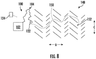
- an exemplary path 150 through an environment 148 for a robotic arm 104 of a robotic arm assembly 100 to position a utility head 122 of the robotic arm 104 at a desired task position and orientation is provided.
- the robot arm assembly 100 may be configured in substantially the same manner as exemplary robot arm assembly 100 described above, and further, the environment 148 may be configured in substantially the same manner as one or more the exemplary gas turbine engine environments described above.
- a position of a base 102, of a root end 110 of the robotic arm 104, or both relative to the environment 148 is known (relative to a coordinate system of the environment 148, which for the embodiment shown is an axial direction A, radial direction R, and circumferential direction C coordinate system).
- the position of the base 102 or root end 110 may be manually input to, e.g., a controller 124 of the robotic arm assembly 100, or alternatively may be determined by the controller 124 using, e.g., one or more sensors of the robotic arm assembly 100.
- the controller 124 may additionally know the orientation of the base 102 or root end 110. Further, the base 102 and/or root end 110 of the robotic arm 104 may be mounted on another robot or joint(s) that allow for the modification of the position and/or orientation of the base 102 and/or root end 110 of the robotic arm 104. With such a configuration, the position and/or orientation of the base 102 or root end 110 may be communicated to the controller 124, or may be controlled by the controller (and therefore known by the controller 124).
- a task position and orientation 152 for the utility member of the robotic arm 104 within the environment 148 is known.
- the task position and orientation 152 may similarly be input into the controller 124, or alternatively may be determined, e.g., as a result of an inspection of the environment 148.
- the controller 124 may note a defect through an inspection of the environment 148, and automatically determine a task position and orientation for the utility head 122 of the robotic arm assembly 100.
- a three-dimensional constraint of the environment 148 is known. The three-dimensional constraint the environment 148 may be determined by the controller 124 using, e.g., a three-dimensional electronic representation or model of the environment 148.
- the controller 124 may use a computer-aided design ("CAD") file, and/or may determine the three-dimensional constraint through inspection or scan of the environment 148.
- the environment 148 may be similar to, e.g., the LP compressor 22 described above with reference to, e.g., Figs. 2 and 3 .
- the three-dimensional constraint of the environment 148 may be determined using, e.g., one or more CAD files for the LP compressor 22 (and turbofan engine 10), a three-dimensional mapping of the LP compressor 22, or any other suitable means.
- the environment 148 may be any other suitable environment, such as any other suitable section of the gas turbine engine, or other engine or system.
- a set of operability limitations of the robotic arm 104 is known (based on an input to the controller 124, or, e.g., by sensing the operability of the robotic arm 104).
- the robotic arm assembly 100 and more specifically, the controller 124 the robotic arm assembly 100, is configured to determine the path 150 for the robotic arm 104 through the environment 148 for positioning the utility implement 122 of the robotic arm 104 in the determined task position and orientation 152 within the environment 148.
- the path 150 may be determined by starting with the known task position and orientation 152, and subsequently constraining the path 150 based on the three-dimensional constraints of the environment 148, the set of operability limitations of the robotic arm 104, and the position of the base 102, the root end 110, or both relative to the environment 148.
- the path 150 may be determined with the end goal of positioning the utility member in the desired task position and orientation 152 as a key parameter.
- Such is an improvement over simply determining the path 150 for the robotic arm 104 in real time as the robotic arm 104 is guided through the environment 148, as it may result in a more efficient path 150 for the robotic arm 104, while ensuring the desired task is achievable by planning the path 150 based on the known task position and orientation 152.
- the path 150 determined for the robotic arm 104 may include a plurality of sequential coordinates (e.g., X1, Y1, Z1; X2, Y2, Z2; X3, Y3, Z3; etc., or rather A1, R1, C1; A2, R2, C2; A3, R3, C3; etc.) for the robotic arm to follow within the three-dimensional environment 148. Additionally, it should be appreciated that the path 150 may also include orientation information for the robotic arm 104 at these positions (and/or between these positions) within the three-dimensional environment 148.
- the orientation information may include angular information for the links 108 of the robotic arm 104 at each of the coordinates relative to each axis of the coordinate system of the environment 148 (e.g., relative to the axial direction A, radial direction R, and circumferential direction C), such that the path 150 includes information for up to six degrees of movement along some or all of the path 150. For example, if a tool or utility member 122 at the distal end of the robotic arm 104 has a greater extent in one dimension than another (e.g., taller than it is wide), it may further be necessary to ensure the robotic arm 104 moves through the three dimensional environment 148 with the appropriate orientation, in addition to the appropriate position.
- determining the path 150 may include determining the path 150 further in view of certain dimensions of the utility member 122 and/or an orientation of the base 102, root end 110, or both (in addition to its position).
- the controller 124 may direct the robotic arm 104 of the robotic arm assembly 100 along the path 150 using a tip-following sequence.
- a tip-following sequence As will be appreciated, when directing the robotic arm 104 through the environment 148 along the path 150 using the tip-following sequence, sequential segments 108 of the robotic arm 104 follow the path 150 of previous segments 108 to ensure that the robotic arm 104 is inserted along the determined path 150. Such may minimize a risk of collision between the robotic arm 104 and the environment 148.
- directing the robotic arm 104 through the environment 148 along the path 150 using the tip-following sequence may include controlling the robotic arm 104 link 108 by link 108, or alternatively by controlling several links 108 as a unit (i.e., a section of the arm 104 as one) to provide for greater degrees of freedom, and/or greater bend angles, than a single joint possesses.
- an exemplary path 150 through an environment 148 for a robotic arm 104 of a robotic arm assembly 100 to position a utility head 122 of the robotic arm 104 at a desired task position and orientation 152 is provided. More specifically, the environment 148 depicted in Fig. 10 is the same environment 148 depicted in Fig. 8 . However, for the embodiment of Fig. 10 , the task position and orientation 152 for utility member is different. For example, the task position and orientation 152 of Fig. 8 may be a first task position and orientation 152A, while the task position and orientation 152 of Fig. 10 is a second task position and orientation 152B. Similarly, the path 150 of Fig. 8 may be a first path 150A, while the path 150 of Fig. 10 is a second path 150B.
- the second path 150B depicted in Fig. 10 for the robotic arm 104 of the robotic arm assembly 100 may be determined in substantially the same way as the path 150 for the robotic arm 104 depicted in Fig. 8 was determined.
- the path 150 was determined based on the second task position and orientation 152B, in addition to the position of the base, the root end, or both relative to the environment, and the three-dimensional constraint of the environment.
- the controller 124 of the robotic arm assembly 100 may determine a transitional movement of the robotic arm 104 from the first path 150A to the second path 150B, and more specifically, may determine the transitional movement by interpolating one or more transitional paths between the first path 150A the second path 150B.
- the first path 150A is depicted overlain with the second path 150B.
- the first path 150A and the second path 150B define a plurality of common points 154.
- the first path 150B defines a plurality of points 156A where the first path 150A does not overlap with the second path 150B
- the second path 150B defines a plurality of points 156B where the second path 150B does not overlap with the first path 150A.
- the controller 124 see Figs.
- the controller 124 may move the robotic arm 104 from the first path 150 to the second path 150 by positioning the joints of the robotic arm 104 sequentially at the intermediate points 158 determined.
- the robotic arm assembly 100 may relatively smoothly and efficiently move from the first task position and orientation 152A to the second task position and orientation 152B.
- the robotic arm assembly may generally include a robotic arm extending between a root end and a distal end, a base, and a utility member.
- the root end of the robotic arm may be coupled to the base, and the distal end of the robotic arm may include the utility member.
- the method 200 generally includes at (202) determining a position of the base, the root end, or both relative to the environment.
- determining the position of the base, the root end, or both relative to the environment at (202) may further include at (203) determining the position and an orientation of the base, the root end, or both relative to the environment.
- the base and/or root end of the robotic arm may be mounted on another robot or joint(s) that allow for the modification of a position and/or an orientation of the base and/or root end of the robotic arm.
- the position and/or orientation of the base or root end may be communicated to a controller of the robotic arm assembly, or may be controlled by the controller of the robotic arm assembly (and therefore known by the controller).
- the method 200 includes at (204) determining a task position and orientation for the utility member within the environment.
- the task position and orientation may generally define a location and, e.g., an angular orientation for the utility member within the environment to facilitate the utility member performing certain operations.
- the task position and orientation may be a task position and orientation to allow the utility member to, e.g., direct a laser drill towards a component to, e.g., drill a hole in the component.
- the task position and orientation may be a position and orientation for the utility member within the environment allow the utility member to, e.g., weld a component within the environment, cut a component within the environment, etc.
- the method 200 further includes at (206) determining a three-dimensional constraint of the environment.
- the environment may be a gas turbine engine.
- determining the three-dimensional constraint of the environment at (206) may include determining the three-dimensional constraint of the environment, and more specifically may include at (208) determining the three-dimensional constraint of the environment using a computer-aided design ("CAD") file of the gas turbine engine.
- CAD computer-aided design
- any other suitable means may be utilized for determining the three-dimensional constraint for the environment.
- determining the three-dimensional constraint for the environment at (206) may include scanning or inspecting the environment using one or more optical sensors or other sensors.
- the exemplary aspect of the method 200 depicted further includes at (210) determining a set of operability limitations of the robotic arm.
- determining the set of operability limitations of the robotic arm at (210) includes at (212) determining a set of joint limitations of the robotic arm (e.g., minimum and/or maximum bend angles, degrees of freedom, etc.), a set of geometric limitations for a plurality of segments of the robotic arm (e.g., lengths of the segments, shapes of the segments, etc.), a set of geometric limitations of a utility member of the robotic arm (e.g., length, width, height, etc.), or combination thereof.
- the operability limitations may further take into consideration an ability of the links of the robotic arm to move in unison, and/or work together to achieve additional degrees of freedom, increased effective bend angles, etc.
- the exemplary method 200 includes at (214) determining a path for the robotic arm through the environment based on each of the position of the base of the robotic arm relative to the environment determined at (202), the task position and orientation for utility member within the environment determined at (204), and the three-dimensional constraint of the environment determined at (206). More specifically, for the exemplary aspect depicted, determining the path for the robotic arm to the environment at (214) further includes at (215) determining the path for the environment further based on the set of operability limitations of the robotic arm determined at (210). In at least certain exemplary aspects, the path for the robotic arm through the environment may include a plurality of sequential vectors for the robotic arm to follow.
- determining the path at (214) may include determining a plurality of sequential coordinates (e.g., X1, Y1, Z1; X2, Y2, Z2; X3, Y3, Z3; etc.) for the robotic arm to follow within the three-dimensional environment. Additionally, it should be appreciated that determining the path at (214) may include determining orientation information for the robotic arm at these positions (and/or between these positions) within the three-dimensional environment. The orientation information may include angular information for the links of the robotic arm at each of the coordinates relative to each axis of the coordinate system of the environment, such that the path includes information for up to six degrees of freedom along some or all of the path.
- a plurality of sequential coordinates e.g., X1, Y1, Z1; X2, Y2, Z2; X3, Y3, Z3; etc.
- a tool at the distal end of the robotic arm may further be necessary to ensure the robotic arm moves through the three dimensional environment with the appropriate orientation, in addition to the appropriate position.
- a more efficient path may be determined for the robotic arm. More specifically, by determining the path for the robotic arm based on the resulting task position and orientation for the utility member may ensure a path for the robotic arm appropriate for the desired task is determined.
- the method 200 further includes, for the exemplary aspect depicted, controlling the snake arm based on the determined path for the snake arm at (214). More specifically, for the exemplary aspect depicted, the method 200 includes at (216) directing the robotic arm tthrough the environment along the path determined for the robotic arm at (214). More specifically, for the exemplary aspect depicted, directing the robotic arm through the environment along the path determined for the robotic arm at (216) includes at (218) directing the robotic arm through the environment along the path using a tip following sequence.
- directing the robotic arm through the environment along the path using a tip following sequence at (218) may include controlling the robotic arm link-by-link, or alternatively by controlling several links as a unit (i.e., a section of the arm as one) to provide for greater degrees of freedom, and/or greater bend angles, than a single joint possesses.
- determining the path at (214) may include determining the path prior to directing the robotic arm through the environment at (216).
- the turbofan task position and orientation for the utility member at (204) may be a first task position and orientation
- the path for the robotic arm through the environment determined at (216) may be a first path for the robotic arm through the environment
- the method 200 further includes at (220) determining a second task position and orientation for the utility member within the environment.
- the second task position and orientation for the utility member within the environment is a different task position and orientation than the first task position and orientation.
- the first task position and orientation for the utility member within the environment may be a starting point of a task
- the second task position and orientation for utility member within the environment may be an ending point of the task.
- the task may be a cutting task, a welding task, etc.
- the first task may be a first drilling hole
- the second task may be a second drilling hole.
- the method 200 further includes at (222) determining a second path for the robotic arm through the environment based on each of the position of the base, the root end, or both relative to the environment, the second task position and orientation the utility member within the environment, and the three-dimensional constraint of the environment. Moreover, the method 200 includes at (224) determining a transitional movement of the robotic arm on the first path to the second path. For the exemplary aspect depicted, determining the transitional movement of the robotic arm from the first path to the second path at (224) includes at (226) interpolating one or more transitional paths between the first path and the second path.
- the method 200 may be a computer-implemented method.
- the above-described steps may be performed by one or more computing devices, such as by the controller 124 described above with reference to Fig. 4 , or any other suitable controller or control system.
- the "environment" through which the exemplary robotic arms extend is described as a gas turbine engine, such as a turbomachine of a gas turbine engine, in other exemplary embodiments and aspects, the exemplary robotic arms described herein may extend through other suitable environments.
- robotic arms may extend through hazardous environments, such as may be found in the nuclear industry, oil drilling industry, etc. Other environments are contemplated as well.
Landscapes
- Engineering & Computer Science (AREA)
- Mechanical Engineering (AREA)
- Robotics (AREA)
- Automation & Control Theory (AREA)
- Manipulator (AREA)
Applications Claiming Priority (1)
| Application Number | Priority Date | Filing Date | Title |
|---|---|---|---|
| US15/986,952 US11084169B2 (en) | 2018-05-23 | 2018-05-23 | System and method for controlling a robotic arm |
Publications (1)
| Publication Number | Publication Date |
|---|---|
| EP3572193A1 true EP3572193A1 (fr) | 2019-11-27 |
Family
ID=66625071
Family Applications (1)
| Application Number | Title | Priority Date | Filing Date |
|---|---|---|---|
| EP19175355.7A Ceased EP3572193A1 (fr) | 2018-05-23 | 2019-05-20 | Système et procédé de commande d'un bras robotique |
Country Status (4)
| Country | Link |
|---|---|
| US (1) | US11084169B2 (fr) |
| EP (1) | EP3572193A1 (fr) |
| CN (1) | CN110524537B (fr) |
| CA (1) | CA3043720C (fr) |
Families Citing this family (26)
| Publication number | Priority date | Publication date | Assignee | Title |
|---|---|---|---|---|
| GB2601942B (en) * | 2015-06-17 | 2022-09-14 | Darkvision Tech Inc | Ultrasonic imaging device and method for wells |
| US11103994B2 (en) * | 2018-07-02 | 2021-08-31 | Teradyne, Inc. | System and method for natural tasking of one or more robots |
| US11707819B2 (en) | 2018-10-15 | 2023-07-25 | General Electric Company | Selectively flexible extension tool |
| US12194620B2 (en) | 2018-10-15 | 2025-01-14 | Oliver Crisipin Robotics Limited | Selectively flexible extension tool |
| US11034026B2 (en) * | 2019-01-10 | 2021-06-15 | General Electric Company | Utilizing optical data to dynamically control operation of a snake-arm robot |
| US11702955B2 (en) | 2019-01-14 | 2023-07-18 | General Electric Company | Component repair system and method |
| GB201903781D0 (en) * | 2019-03-20 | 2019-05-01 | Rolls Royce Plc | Probe guiding |
| US12405187B2 (en) | 2019-10-04 | 2025-09-02 | General Electric Company | Insertion apparatus for use with rotary machines |
| US11692650B2 (en) | 2020-01-23 | 2023-07-04 | General Electric Company | Selectively flexible extension tool |
| US11752622B2 (en) | 2020-01-23 | 2023-09-12 | General Electric Company | Extension tool having a plurality of links |
| US11613003B2 (en) | 2020-01-24 | 2023-03-28 | General Electric Company | Line assembly for an extension tool having a plurality of links |
| JP7375587B2 (ja) * | 2020-02-05 | 2023-11-08 | 株式会社デンソー | 軌道生成装置、多リンクシステム、及び軌道生成方法 |
| US11371437B2 (en) | 2020-03-10 | 2022-06-28 | Oliver Crispin Robotics Limited | Insertion tool |
| US12091981B2 (en) * | 2020-06-11 | 2024-09-17 | General Electric Company | Insertion tool and method |
| US12416800B2 (en) | 2021-01-08 | 2025-09-16 | General Electric Company | Insertion tool |
| US12504616B2 (en) | 2021-01-08 | 2025-12-23 | General Electric Company | Insertion tool |
| US11654547B2 (en) | 2021-03-31 | 2023-05-23 | General Electric Company | Extension tool |
| US12586226B2 (en) | 2021-07-13 | 2026-03-24 | General Electric Company | Method for inspecting an object |
| US12602808B2 (en) | 2021-07-13 | 2026-04-14 | General Electric Company | Method for inspecting an object |
| US12596076B2 (en) | 2022-11-11 | 2026-04-07 | General Electric Company | Inspection systems and methods employing different wavelength directional light for enhanced imaging |
| US12610116B2 (en) | 2022-11-11 | 2026-04-21 | General Electric Company | Inspection systems and methods employing directional light for enhanced imaging |
| US12495214B2 (en) | 2023-03-15 | 2025-12-09 | General Electric Company | Pulse illumination imaging of a target element |
| WO2024258779A1 (fr) * | 2023-06-12 | 2024-12-19 | General Electric Company | Systèmes et procédés d'inspection de moteur |
| US12593131B2 (en) | 2023-09-05 | 2026-03-31 | General Electric Company | Velocity matching imaging of a target element |
| EP4521166A1 (fr) | 2023-09-05 | 2025-03-12 | General Electric Company | Imagerie par correspondance de vitesse d'un élément cible |
| US20260104243A1 (en) | 2024-10-14 | 2026-04-16 | General Electric Company | Insertion tool for inspection |
Citations (5)
| Publication number | Priority date | Publication date | Assignee | Title |
|---|---|---|---|---|
| EP1862876A1 (fr) * | 2005-05-13 | 2007-12-05 | Toyota Jidosha Kabushiki Kaisha | Dispositif de planification de parcours |
| US20110106306A1 (en) * | 2009-11-02 | 2011-05-05 | Samsung Electronics Co., Ltd. | Path planning apparatus of robot and method and computer-readable medium thereof |
| US20110172818A1 (en) * | 2010-01-12 | 2011-07-14 | Honda Motor Co., Ltd. | Trajectory planning method, trajectory planning system and robot |
| US8972057B1 (en) * | 2013-01-09 | 2015-03-03 | The Boeing Company | Systems and methods for generating a robotic path plan in a confined configuration space |
| CN107234617A (zh) * | 2017-07-10 | 2017-10-10 | 北京邮电大学 | 一种避障任务无关人工势场引导的避障路径规划方法 |
Family Cites Families (83)
| Publication number | Priority date | Publication date | Assignee | Title |
|---|---|---|---|---|
| US4260941A (en) | 1975-10-28 | 1981-04-07 | Unimation, Inc. | Programmable automatic assembly system |
| US4118220A (en) * | 1976-07-19 | 1978-10-03 | Nichols Engineering & Research Corp. | Method for treating waste material |
| US4613269A (en) * | 1984-02-28 | 1986-09-23 | Object Recognition Systems, Inc. | Robotic acquisition of objects by means including histogram techniques |
| US4620362A (en) * | 1984-06-22 | 1986-11-04 | The Boeing Company | Changeable tooling system for robot end-effector |
| CA1234696A (fr) * | 1985-03-20 | 1988-04-05 | Grigori S. Victorovich | Procede de metallurgie iii |
| KR900008539B1 (ko) | 1985-05-30 | 1990-11-24 | 마쯔시다덴기산교 가부시기가이샤 | 로보트의 연속경로 제어방법 |
| US4975856A (en) * | 1986-02-18 | 1990-12-04 | Robotics Research Corporation | Motion controller for redundant or nonredundant linkages |
| US4937759A (en) * | 1986-02-18 | 1990-06-26 | Robotics Research Corporation | Industrial robot with controller |
| US4706324A (en) * | 1986-10-17 | 1987-11-17 | Goodspeed Byron Lester | Apparatus for automatically cleaning smelt spouts of a chemical recovery furnace |
| US4831549A (en) | 1987-07-28 | 1989-05-16 | Brigham Young University | Device and method for correction of robot inaccuracy |
| JP3211754B2 (ja) * | 1996-11-28 | 2001-09-25 | 宇部興産株式会社 | 半溶融成形用金属の製造装置 |
| US5179329A (en) | 1989-04-25 | 1993-01-12 | Shinko Electric Co., Ltd. | Travel control method, travel control device, and mobile robot for mobile robot systems |
| US5041907A (en) * | 1990-01-29 | 1991-08-20 | Technistar Corporation | Automated assembly and packaging system |
| US5310248A (en) * | 1991-07-19 | 1994-05-10 | Colorado School Of Mines | Automatic vein identifying method and follower apparatus for use in a robot mining system |
| US5237468A (en) * | 1991-10-15 | 1993-08-17 | International Business Machines Corporation | Camera and gripper assembly for an automated storage library |
| US5443354A (en) * | 1992-07-20 | 1995-08-22 | The United States Of America As Represented By The Administrator Of The National Aeronautics And Space Administration | Hazardous materials emergency response mobile robot |
| US5542650A (en) * | 1995-02-10 | 1996-08-06 | Anthony-Ross Company | Apparatus for automatically cleaning smelt spouts of a chemical recovery furnace |
| DE19708376C1 (de) * | 1997-03-01 | 1998-07-02 | Gasteier & Bilke Verfahrenstec | Verwendung eines Briketts aus Abfallmaterialien als Zuschlagstoff für Schmelzöfen einer Eisengießerei |
| DE19804195A1 (de) | 1998-02-03 | 1999-08-05 | Siemens Ag | Bahnplanungsverfahren für eine mobile Einheit zur Flächenbearbeitung |
| US20010056313A1 (en) * | 2000-05-08 | 2001-12-27 | Osborne William Joseph | Object locating and retrieving system utilizing labels |
| US6459760B1 (en) * | 2000-07-28 | 2002-10-01 | Exotic Metals Forming Company, Inc. | Apparatuses and methods for non-destructive inspection |
| GB0020461D0 (en) * | 2000-08-18 | 2000-10-11 | Oliver Crispin Consulting Ltd | Improvements in and relating to the robotic positioning of a work tool to a sensor |
| WO2002082195A2 (fr) * | 2001-04-05 | 2002-10-17 | Siemens Aktiengesellschaft | Intelligence robotique en environnement naturel |
| US8219246B2 (en) | 2001-06-13 | 2012-07-10 | Oliver Crispin Robotics Limited | System and method for controlling a robotic arm |
| US6579091B1 (en) * | 2002-01-10 | 2003-06-17 | Andritz Oy | Cleaning device for cleaning air ports of a furnace |
| US7975658B2 (en) * | 2002-05-09 | 2011-07-12 | Clyde Bergemann, Inc. | Air port and smelt spout cleaner and drop jaw tip |
| US20030212505A1 (en) * | 2002-05-13 | 2003-11-13 | Rojas Luis Paredes | System for a non-invasive online continuous measurement of phase levels in converters or pyrometallurgical furnaces |
| US7039499B1 (en) * | 2002-08-02 | 2006-05-02 | Seminet Inc. | Robotic storage buffer system for substrate carrier pods |
| JP2006504520A (ja) * | 2002-10-29 | 2006-02-09 | ミッタル スチール サウス アフリカ リミテッド | ガス浄化法とその装置 |
| US20040179924A1 (en) * | 2003-03-11 | 2004-09-16 | Lundahl Robert Dana | Robotic package unloading machine |
| US6830605B2 (en) * | 2003-03-14 | 2004-12-14 | World Resources Company | Recovery of metal values from cermet |
| KR100825975B1 (ko) * | 2003-07-29 | 2008-04-28 | 뵈스트알파인 스탈 게엠베하 | 경화 강판 부품의 제조 방법 |
| US7765780B2 (en) * | 2003-12-12 | 2010-08-03 | Vision Robotics Corporation | Agricultural robot system and method |
| US7327869B2 (en) * | 2004-06-21 | 2008-02-05 | The Boeing Company | Computer aided quality assurance software system |
| US7409263B2 (en) * | 2004-07-14 | 2008-08-05 | Applied Materials, Inc. | Methods and apparatus for repositioning support for a substrate carrier |
| US7640810B2 (en) * | 2005-07-11 | 2010-01-05 | The Boeing Company | Ultrasonic inspection apparatus, system, and method |
| US20060218680A1 (en) * | 2005-03-28 | 2006-09-28 | Bailey Andrew D Iii | Apparatus for servicing a plasma processing system with a robot |
| JP4729345B2 (ja) * | 2005-05-30 | 2011-07-20 | 博明 山口 | 移動機構、移動機構用部材及び該移動機構の制御方法 |
| US20100057254A1 (en) * | 2006-11-13 | 2010-03-04 | Salamanca Hugo P | Methods for using robotics in mining and post-mining processing |
| US7930065B2 (en) * | 2005-12-30 | 2011-04-19 | Intuitive Surgical Operations, Inc. | Robotic surgery system including position sensors using fiber bragg gratings |
| US7735435B2 (en) * | 2006-05-24 | 2010-06-15 | Diamond Power International, Inc. | Apparatus for cleaning a smelt spout of a combustion device |
| FI122899B (fi) * | 2006-10-16 | 2012-08-31 | Metso Power Oy | Soodakattilan sulakourun puhdistin |
| US7784348B2 (en) * | 2006-12-22 | 2010-08-31 | Lockheed Martin Corporation | Articulated robot for laser ultrasonic inspection |
| US7625518B2 (en) * | 2007-01-03 | 2009-12-01 | Clyde Bergemann, Inc. | Smelt spout opening cleaner, cleaning head and apparatus |
| US20090118864A1 (en) * | 2007-11-01 | 2009-05-07 | Bryce Eldridge | Method and system for finding a tool center point for a robot using an external camera |
| GB2455804A (en) * | 2007-12-21 | 2009-06-24 | Oliver Crispin Robotics Ltd | A robotic arm for use with a rotary machine |
| EP2119990A1 (fr) * | 2008-05-16 | 2009-11-18 | Siemens Aktiengesellschaft | Installation de four |
| WO2010001107A2 (fr) * | 2008-06-30 | 2010-01-07 | Oliver Crispin Robotics Limited | Procédé de commande d’un bras robotique |
| KR20110015765A (ko) | 2009-08-10 | 2011-02-17 | 삼성전자주식회사 | 로봇의 경로계획장치 및 그 방법 |
| US8340820B2 (en) | 2010-02-26 | 2012-12-25 | Agilent Technologies, Inc. | Robot arm and method of controlling robot arm to avoid collisions |
| US9149929B2 (en) * | 2010-05-26 | 2015-10-06 | The Boeing Company | Methods and systems for inspection sensor placement |
| US9031734B2 (en) * | 2010-09-29 | 2015-05-12 | Aerobotics, Inc. | Systems and methods for non-destructive inspection of airplanes |
| KR101234634B1 (ko) * | 2010-12-08 | 2013-02-19 | 현대자동차주식회사 | 레이저 용접 및 비젼 검사 겸용 그리퍼 장치 |
| US9020636B2 (en) * | 2010-12-16 | 2015-04-28 | Saied Tadayon | Robot for solar farms |
| US8706340B2 (en) * | 2011-04-19 | 2014-04-22 | Electric Power Research Institute, Inc. | Underground utility vault inspection system and method |
| KR101876380B1 (ko) | 2011-07-06 | 2018-07-11 | 삼성전자주식회사 | 매니퓰레이터 및 그 경로 생성 방법 |
| US8573076B2 (en) * | 2011-07-11 | 2013-11-05 | The Boeing Company | Non-destructive inspection systems and methods that incorporate interchangeable probes |
| US8930042B2 (en) * | 2011-07-15 | 2015-01-06 | The Boeing Company | Mobilized sensor network for structural health monitoring |
| US20150032387A1 (en) * | 2012-01-06 | 2015-01-29 | Aerobotics, Inc. | Novel systems and methods that facilitate underside inspection of crafts |
| US9539726B2 (en) * | 2012-04-20 | 2017-01-10 | Vanderbilt University | Systems and methods for safe compliant insertion and hybrid force/motion telemanipulation of continuum robots |
| US9939411B2 (en) * | 2012-07-12 | 2018-04-10 | The Boeing Company | Extended reach inspection apparatus |
| US9327401B2 (en) * | 2012-09-10 | 2016-05-03 | Fanuc America Corporation | Method of controlling a redundant robot |
| HUE043828T2 (hu) * | 2013-03-15 | 2019-09-30 | Univ Carnegie Mellon | Felügyelt autonóm robot rendszer komplex felületvizsgálathoz és feldolgozáshoz |
| SE537534C2 (sv) * | 2013-08-27 | 2015-06-02 | Cognibotics Ab | Metod och system för bestämning av åtminstone en egenskap hos en manipulator |
| US20150128717A1 (en) * | 2013-11-13 | 2015-05-14 | Gary J. May | Automated dynamic laser bond inspection system |
| KR101510336B1 (ko) * | 2013-11-14 | 2015-04-07 | 현대자동차 주식회사 | 차량용 운전자 지원 시스템의 검사 장치 |
| US9358685B2 (en) * | 2014-02-03 | 2016-06-07 | Brain Corporation | Apparatus and methods for control of robot actions based on corrective user inputs |
| DE102015204641B4 (de) * | 2014-06-03 | 2021-03-25 | ArtiMinds Robotics GmbH | Verfahren und System zur Programmierung eines Roboters |
| US9505051B2 (en) * | 2014-07-09 | 2016-11-29 | The Boeing Company | Mobile platforms for performing operations along an exterior of a fuselage assembly |
| US9873230B1 (en) * | 2014-08-19 | 2018-01-23 | The Boeing Company | Mobile system for automated layup and compaction of composite laminates |
| US9804593B1 (en) * | 2014-12-12 | 2017-10-31 | X Development Llc | Methods and systems for teaching positions to components of devices |
| CN104626206B (zh) * | 2014-12-17 | 2016-04-20 | 西南科技大学 | 一种非结构环境下机器人作业的位姿信息测量方法 |
| GB2542566A (en) * | 2015-09-22 | 2017-03-29 | Rolls Royce Plc | Apparatus, methods, computer programs, and non-transitory computer readable storage mediums for controlling movement of robotic machinery |
| US10143526B2 (en) * | 2015-11-30 | 2018-12-04 | Auris Health, Inc. | Robot-assisted driving systems and methods |
| US10213883B2 (en) * | 2016-02-22 | 2019-02-26 | General Electric Company | System and method for in situ repair of gas turbine engine casing clearance |
| US10563510B2 (en) * | 2016-03-18 | 2020-02-18 | General Electric Company | System and method for in situ repair of gas turbine engines |
| US10019566B1 (en) * | 2016-04-14 | 2018-07-10 | X Development Llc | Authorizing robot use and/or adapting physical control parameters for a robot |
| US9687983B1 (en) * | 2016-05-11 | 2017-06-27 | X Development Llc | Generating a grasp pose for grasping of an object by a grasping end effector of a robot |
| GB2551769B (en) * | 2016-06-30 | 2020-02-19 | Rolls Royce Plc | Methods, apparatus, computer programs and non-transitory computer readable storage mediums for controlling a robot within a volume |
| GB201615149D0 (en) * | 2016-09-07 | 2016-10-19 | Rolls Royce Plc | Gas shielding arrangements for gas turbine engines |
| US10371646B2 (en) * | 2016-09-19 | 2019-08-06 | The Boeing Company | Method and system for automated data collection and part validation |
| GB2557179B (en) * | 2016-11-29 | 2020-01-01 | Rolls Royce Plc | Methods, apparatus, computer programs and non-transitory computer readable storage mediums for controlling a hyper redundant manipulator |
| US10786910B2 (en) * | 2017-08-21 | 2020-09-29 | Massachusetts Institute Of Technology | Extending robotic arm |
-
2018
- 2018-05-23 US US15/986,952 patent/US11084169B2/en active Active
-
2019
- 2019-05-17 CA CA3043720A patent/CA3043720C/fr active Active
- 2019-05-20 EP EP19175355.7A patent/EP3572193A1/fr not_active Ceased
- 2019-05-22 CN CN201910430044.0A patent/CN110524537B/zh active Active
Patent Citations (5)
| Publication number | Priority date | Publication date | Assignee | Title |
|---|---|---|---|---|
| EP1862876A1 (fr) * | 2005-05-13 | 2007-12-05 | Toyota Jidosha Kabushiki Kaisha | Dispositif de planification de parcours |
| US20110106306A1 (en) * | 2009-11-02 | 2011-05-05 | Samsung Electronics Co., Ltd. | Path planning apparatus of robot and method and computer-readable medium thereof |
| US20110172818A1 (en) * | 2010-01-12 | 2011-07-14 | Honda Motor Co., Ltd. | Trajectory planning method, trajectory planning system and robot |
| US8972057B1 (en) * | 2013-01-09 | 2015-03-03 | The Boeing Company | Systems and methods for generating a robotic path plan in a confined configuration space |
| CN107234617A (zh) * | 2017-07-10 | 2017-10-10 | 北京邮电大学 | 一种避障任务无关人工势场引导的避障路径规划方法 |
Non-Patent Citations (3)
| Title |
|---|
| "Robotics", 31 December 2009, SPRINGER LONDON, London, ISBN: 978-1-84628-642-1, ISSN: 1439-2232, article BRUNO SICILIANO ET AL: "Robotics - chapters 2-4", pages: 39 - 189, XP055615186 * |
| "RoManSy 6", 1 January 1987, SPRINGER US, Boston, MA, ISBN: 978-1-4684-6915-8, article L. SCIAVICCO ET AL: "Solving the Inverse Kinematic Problem for Robotic Manipulators", pages: 107 - 114, XP055762444, DOI: 10.1007/978-1-4684-6915-8_9 * |
| DONG X ET AL: "Development of a slender continuum robotic system for on-wing inspection/repair of gas turbine engines", ROBOTICS AND COMPUTER INTEGRATED MANUFACTURING, ELSEVIER SCIENCE PUBLISHERS BV., BARKING, GB, vol. 44, 29 September 2016 (2016-09-29), pages 218 - 229, XP029830825, ISSN: 0736-5845, DOI: 10.1016/J.RCIM.2016.09.004 * |
Also Published As
| Publication number | Publication date |
|---|---|
| US20190358813A1 (en) | 2019-11-28 |
| CN110524537B (zh) | 2023-05-26 |
| CA3043720A1 (fr) | 2019-11-23 |
| US11084169B2 (en) | 2021-08-10 |
| CN110524537A (zh) | 2019-12-03 |
| CA3043720C (fr) | 2022-01-18 |
Similar Documents
| Publication | Publication Date | Title |
|---|---|---|
| CA3043720C (fr) | Systeme et procede de commande d'un bras robotique | |
| CA3120629C (fr) | Outil d'insertion et methode | |
| US12420953B2 (en) | Inspection and repair tool | |
| EP3572632B1 (fr) | Outil et procédé d'inspection | |
| US10822997B2 (en) | Inspection tool and method | |
| EP3548712A1 (fr) | Outil de maintenance de moteur à turbine à gaz | |
| EP3567214A1 (fr) | Procédé in-situ de rétablissement d'une précontrainte de la virole des aubes d'une turbine à gaz | |
| US10815783B2 (en) | In situ engine component repair | |
| EP3859126A1 (fr) | Inspection de moteur de turbine et outil de maintenance | |
| CA3101621C (fr) | Systeme et procede d'execution d'operations sur un moteur |
Legal Events
| Date | Code | Title | Description |
|---|---|---|---|
| PUAI | Public reference made under article 153(3) epc to a published international application that has entered the european phase |
Free format text: ORIGINAL CODE: 0009012 |
|
| STAA | Information on the status of an ep patent application or granted ep patent |
Free format text: STATUS: THE APPLICATION HAS BEEN PUBLISHED |
|
| AK | Designated contracting states |
Kind code of ref document: A1 Designated state(s): AL AT BE BG CH CY CZ DE DK EE ES FI FR GB GR HR HU IE IS IT LI LT LU LV MC MK MT NL NO PL PT RO RS SE SI SK SM TR |
|
| AX | Request for extension of the european patent |
Extension state: BA ME |
|
| STAA | Information on the status of an ep patent application or granted ep patent |
Free format text: STATUS: REQUEST FOR EXAMINATION WAS MADE |
|
| 17P | Request for examination filed |
Effective date: 20200527 |
|
| RBV | Designated contracting states (corrected) |
Designated state(s): AL AT BE BG CH CY CZ DE DK EE ES FI FR GB GR HR HU IE IS IT LI LT LU LV MC MK MT NL NO PL PT RO RS SE SI SK SM TR |
|
| STAA | Information on the status of an ep patent application or granted ep patent |
Free format text: STATUS: EXAMINATION IS IN PROGRESS |
|
| 17Q | First examination report despatched |
Effective date: 20210114 |
|
| STAA | Information on the status of an ep patent application or granted ep patent |
Free format text: STATUS: THE APPLICATION HAS BEEN REFUSED |
|
| 18R | Application refused |
Effective date: 20221103 |