EP3572216A1 - Dispositif de mesure et procédé de mesure de la tension de mèches en fibre de carbone - Google Patents
Dispositif de mesure et procédé de mesure de la tension de mèches en fibre de carbone Download PDFInfo
- Publication number
- EP3572216A1 EP3572216A1 EP19176047.9A EP19176047A EP3572216A1 EP 3572216 A1 EP3572216 A1 EP 3572216A1 EP 19176047 A EP19176047 A EP 19176047A EP 3572216 A1 EP3572216 A1 EP 3572216A1
- Authority
- EP
- European Patent Office
- Prior art keywords
- tension
- measurement device
- fiber tows
- readings
- carbon fiber
- Prior art date
- Legal status (The legal status is an assumption and is not a legal conclusion. Google has not performed a legal analysis and makes no representation as to the accuracy of the status listed.)
- Withdrawn
Links
Images


Classifications
-
- B—PERFORMING OPERATIONS; TRANSPORTING
- B29—WORKING OF PLASTICS; WORKING OF SUBSTANCES IN A PLASTIC STATE IN GENERAL
- B29C—SHAPING OR JOINING OF PLASTICS; SHAPING OF MATERIAL IN A PLASTIC STATE, NOT OTHERWISE PROVIDED FOR; AFTER-TREATMENT OF THE SHAPED PRODUCTS, e.g. REPAIRING
- B29C64/00—Additive manufacturing, i.e. manufacturing of three-dimensional [3D] objects by additive deposition, additive agglomeration or additive layering, e.g. by 3D printing, stereolithography or selective laser sintering
- B29C64/20—Apparatus for additive manufacturing; Details thereof or accessories therefor
- B29C64/205—Means for applying layers
- B29C64/209—Heads; Nozzles
-
- B—PERFORMING OPERATIONS; TRANSPORTING
- B25—HAND TOOLS; PORTABLE POWER-DRIVEN TOOLS; MANIPULATORS
- B25J—MANIPULATORS; CHAMBERS PROVIDED WITH MANIPULATION DEVICES
- B25J11/00—Manipulators not otherwise provided for
-
- B—PERFORMING OPERATIONS; TRANSPORTING
- B29—WORKING OF PLASTICS; WORKING OF SUBSTANCES IN A PLASTIC STATE IN GENERAL
- B29C—SHAPING OR JOINING OF PLASTICS; SHAPING OF MATERIAL IN A PLASTIC STATE, NOT OTHERWISE PROVIDED FOR; AFTER-TREATMENT OF THE SHAPED PRODUCTS, e.g. REPAIRING
- B29C64/00—Additive manufacturing, i.e. manufacturing of three-dimensional [3D] objects by additive deposition, additive agglomeration or additive layering, e.g. by 3D printing, stereolithography or selective laser sintering
- B29C64/30—Auxiliary operations or equipment
- B29C64/386—Data acquisition or data processing for additive manufacturing
- B29C64/393—Data acquisition or data processing for additive manufacturing for controlling or regulating additive manufacturing processes
-
- B—PERFORMING OPERATIONS; TRANSPORTING
- B29—WORKING OF PLASTICS; WORKING OF SUBSTANCES IN A PLASTIC STATE IN GENERAL
- B29C—SHAPING OR JOINING OF PLASTICS; SHAPING OF MATERIAL IN A PLASTIC STATE, NOT OTHERWISE PROVIDED FOR; AFTER-TREATMENT OF THE SHAPED PRODUCTS, e.g. REPAIRING
- B29C70/00—Shaping composites, i.e. plastics material comprising reinforcements, fillers or preformed parts, e.g. inserts
- B29C70/04—Shaping composites, i.e. plastics material comprising reinforcements, fillers or preformed parts, e.g. inserts comprising reinforcements only, e.g. self-reinforcing plastics
- B29C70/06—Fibrous reinforcements only
- B29C70/10—Fibrous reinforcements only characterised by the structure of fibrous reinforcements, e.g. hollow fibres
- B29C70/16—Fibrous reinforcements only characterised by the structure of fibrous reinforcements, e.g. hollow fibres using fibres of substantial or continuous length
- B29C70/20—Fibrous reinforcements only characterised by the structure of fibrous reinforcements, e.g. hollow fibres using fibres of substantial or continuous length oriented in a single direction, e.g. roofing or other parallel fibres
-
- B—PERFORMING OPERATIONS; TRANSPORTING
- B29—WORKING OF PLASTICS; WORKING OF SUBSTANCES IN A PLASTIC STATE IN GENERAL
- B29C—SHAPING OR JOINING OF PLASTICS; SHAPING OF MATERIAL IN A PLASTIC STATE, NOT OTHERWISE PROVIDED FOR; AFTER-TREATMENT OF THE SHAPED PRODUCTS, e.g. REPAIRING
- B29C70/00—Shaping composites, i.e. plastics material comprising reinforcements, fillers or preformed parts, e.g. inserts
- B29C70/04—Shaping composites, i.e. plastics material comprising reinforcements, fillers or preformed parts, e.g. inserts comprising reinforcements only, e.g. self-reinforcing plastics
- B29C70/28—Shaping operations therefor
- B29C70/30—Shaping by lay-up, i.e. applying fibres, tape or broadsheet on a mould, former or core; Shaping by spray-up, i.e. spraying of fibres on a mould, former or core
- B29C70/38—Automated lay-up, e.g. using robots, laying filaments according to predetermined patterns
- B29C70/382—Automated fiber placement [AFP]
- B29C70/384—Fiber placement heads, e.g. component parts, details or accessories
-
- B—PERFORMING OPERATIONS; TRANSPORTING
- B33—ADDITIVE MANUFACTURING TECHNOLOGY
- B33Y—ADDITIVE MANUFACTURING, i.e. MANUFACTURING OF THREE-DIMENSIONAL [3D] OBJECTS BY ADDITIVE DEPOSITION, ADDITIVE AGGLOMERATION OR ADDITIVE LAYERING, e.g. BY 3D PRINTING, STEREOLITHOGRAPHY OR SELECTIVE LASER SINTERING
- B33Y30/00—Apparatus for additive manufacturing; Details thereof or accessories therefor
-
- B—PERFORMING OPERATIONS; TRANSPORTING
- B33—ADDITIVE MANUFACTURING TECHNOLOGY
- B33Y—ADDITIVE MANUFACTURING, i.e. MANUFACTURING OF THREE-DIMENSIONAL [3D] OBJECTS BY ADDITIVE DEPOSITION, ADDITIVE AGGLOMERATION OR ADDITIVE LAYERING, e.g. BY 3D PRINTING, STEREOLITHOGRAPHY OR SELECTIVE LASER SINTERING
- B33Y50/00—Data acquisition or data processing for additive manufacturing
- B33Y50/02—Data acquisition or data processing for additive manufacturing for controlling or regulating additive manufacturing processes
-
- G—PHYSICS
- G01—MEASURING; TESTING
- G01L—MEASURING FORCE, STRESS, TORQUE, WORK, MECHANICAL POWER, MECHANICAL EFFICIENCY, OR FLUID PRESSURE
- G01L5/00—Apparatus for, or methods of, measuring force, work, mechanical power, or torque, specially adapted for specific purposes
- G01L5/0028—Force sensors associated with force applying means
-
- G—PHYSICS
- G01—MEASURING; TESTING
- G01L—MEASURING FORCE, STRESS, TORQUE, WORK, MECHANICAL POWER, MECHANICAL EFFICIENCY, OR FLUID PRESSURE
- G01L5/00—Apparatus for, or methods of, measuring force, work, mechanical power, or torque, specially adapted for specific purposes
- G01L5/04—Apparatus for, or methods of, measuring force, work, mechanical power, or torque, specially adapted for specific purposes for measuring tension in flexible members, e.g. ropes, cables, wires, threads, belts or bands
- G01L5/10—Apparatus for, or methods of, measuring force, work, mechanical power, or torque, specially adapted for specific purposes for measuring tension in flexible members, e.g. ropes, cables, wires, threads, belts or bands using electrical means
- G01L5/103—Apparatus for, or methods of, measuring force, work, mechanical power, or torque, specially adapted for specific purposes for measuring tension in flexible members, e.g. ropes, cables, wires, threads, belts or bands using electrical means using sensors fixed at one end of the flexible member
-
- B—PERFORMING OPERATIONS; TRANSPORTING
- B29—WORKING OF PLASTICS; WORKING OF SUBSTANCES IN A PLASTIC STATE IN GENERAL
- B29C—SHAPING OR JOINING OF PLASTICS; SHAPING OF MATERIAL IN A PLASTIC STATE, NOT OTHERWISE PROVIDED FOR; AFTER-TREATMENT OF THE SHAPED PRODUCTS, e.g. REPAIRING
- B29C64/00—Additive manufacturing, i.e. manufacturing of three-dimensional [3D] objects by additive deposition, additive agglomeration or additive layering, e.g. by 3D printing, stereolithography or selective laser sintering
- B29C64/10—Processes of additive manufacturing
- B29C64/141—Processes of additive manufacturing using only solid materials
-
- B—PERFORMING OPERATIONS; TRANSPORTING
- B29—WORKING OF PLASTICS; WORKING OF SUBSTANCES IN A PLASTIC STATE IN GENERAL
- B29K—INDEXING SCHEME ASSOCIATED WITH SUBCLASSES B29B, B29C OR B29D, RELATING TO MOULDING MATERIALS OR TO MATERIALS FOR MOULDS, REINFORCEMENTS, FILLERS OR PREFORMED PARTS, e.g. INSERTS
- B29K2307/00—Use of elements other than metals as reinforcement
- B29K2307/04—Carbon
-
- B—PERFORMING OPERATIONS; TRANSPORTING
- B33—ADDITIVE MANUFACTURING TECHNOLOGY
- B33Y—ADDITIVE MANUFACTURING, i.e. MANUFACTURING OF THREE-DIMENSIONAL [3D] OBJECTS BY ADDITIVE DEPOSITION, ADDITIVE AGGLOMERATION OR ADDITIVE LAYERING, e.g. BY 3D PRINTING, STEREOLITHOGRAPHY OR SELECTIVE LASER SINTERING
- B33Y10/00—Processes of additive manufacturing
Definitions
- the present disclosure concerns a measurement device, such as a tensiometer, and a method for measuring the tension in carbon fiber tows.
- a carbon fiber tow is a tape containing carbon fiber filaments disposed in an uncured resin matrix.
- the carbon fiber tows are layered atop one another until the composite component achieves the desired thickness.
- the laying of the carbon fiber tows is not continuous.
- the carbon fiber tows which are typically deposited in parallel lines, are not deposited in the space where the window will be positioned.
- the lengths of the carbon fiber tows are adjusted so that individual ones of the carbon fiber tows terminate at opposite sides of the opening.
- AFP Advanced Fiber Placement
- the tension established in each of the tows may impact the laying of each tow onto the mold or onto previously-deposited layers of carbon fiber tows. This tension may cause a "late-start” or a missing tow in the placement of the tows, causing them to be out-of-tolerance, which can impact the quality of the final composite component.
- a need has developed to rapidly and accurately measure the tension in the plurality of carbon fiber tows that are to be deposited onto a surface of a mold when fabricating a carbon fiber component using a robot.
- a measurement device for simultaneously measuring the tension in a plurality of fiber tows mounted within a deposition head of a fiber placement robot includes a plurality of load cells and a plurality of connectors. Each of the plurality of connectors is connected to a respective one of the plurality of load cells. Each of the plurality of connectors is adapted to be connected to a respective one of the plurality of fiber tows. Movement of the fiber placement robot in relation to the measurement device may generate a plurality of measured tension readings, each of the plurality of measured tension readings being associated with a respective tension in each of the plurality of fiber tows.
- the measurement device may also include at least one controller.
- the controller may receive the plurality of measured tension readings from the plurality of load cells, compare each of the plurality of measured tension readings to a predetermined tension, and output a deviation signal indicative of whether one or more of the plurality of tension readings deviates from the predetermined tension.
- the at least one controller includes a plurality of microcontrollers.
- Each of the plurality of microcontrollers may be associated with each of the plurality of load cells.
- the measurement device includes a display for displaying an output of the deviation signal if one or more of the plurality of tension readings deviates from the predetermined tension.
- the display may display an indication of a deviance of a measured tension reading from the predetermined tension.
- the deviation signal may encompass a plurality of deviation signals, each being associated with one of the plurality of tension readings.
- the indication of a deviance of a measured tension reading may be a visual indication of an out-of-tolerance condition.
- the measurement device may include a machine-readable memory unit for storing the plurality of measured tension readings.
- the machine-readable memory unit also may store the predetermined tension.
- the machine-readable memory unit may store the deviation signal.
- the plurality of load cells may simultaneously generate the plurality of measured tension readings.
- the plurality of load cells comprises sixteen load cells.
- the measurement device may include a housing, sixteen connectors, each being connected to one of the sixteen load cells, and sixteen load bars disposed in the housing between the sixteen connectors and the sixteen load cells.
- the sixteen load bars may be arranged to flex under tension and cooperate with the sixteen load cells to generate the plurality of measured tension readings.
- sixteen load bars are arranged in the housing in a first row of eight load bars and a second row of eight load bars.
- a method for determining a measured tension in each of a plurality of fiber tows at a head of a robot adapted to deposit the plurality of fiber tows onto a mold, the measured tension being determined by a measurement device comprising a plurality of load cells and a plurality of connectors each connected respectively to one of the plurality of load cells.
- the method may include, upon attachment of each of the plurality of fiber tows to a respective one of the plurality of load cells, obtaining a plurality of measured tension readings, each of the plurality of measured tension readings being associated with a respective tension in each of the plurality of fiber tows.
- the method may include comparing each of the plurality of measured tension readings to a predetermined tension value and generating at least one deviation signal indicative of whether one or more of the plurality of measured tension readings deviates from a predetermined tension value based on the comparing.
- the method may include causing adjustment to at least one parameter associated with the operation of the fiber placement robot in response to the generating of the at least one deviation signal.
- At least one controller may be connected to the measurement device.
- the controller may compare the measured tension readings with the predetermined tension value in each of the plurality of fiber tows.
- the controller may determine a deviation between the measured tension readings and the predetermined tension value for each of the plurality of fiber tows.
- the controller may be arranged to adjust the at least one operational parameter.
- embodiments of the present invention are described in connection with the manufacture of a component from a plurality of carbon fiber tows that are layered atop one another until the component acquires a suitable thickness. More specifically, the embodiments are described in connection with the layering of carbon fiber tows by an automated device, such as a fiber placement robot.
- the present invention should not be understood to be limited to the manufacture of composite components from carbon fibers tows.
- the present invention encompasses the manufacture of composite components from tows incorporating any number of materials, as should be apparent to those skilled in the art.
- some tows include one or more of aramid fibers, nylon fibers, polyester fibers, glass fibers, metal fibers, and the like. These fibers may or may not be combined with carbon fibers to create the individual tow.
- the present invention should not be understood to be limited solely to the application of carbon fiber tows from a fiber placement robot. To the contrary, an automated application device other than a fiber placement robot may be employed.
- embodiments of the present invention are discussed in connection with the fabrication of composite components that may be incorporated into an aircraft.
- the present invention is contemplated to encompass composite components manufactured for any suitable purpose and should not be understood to be limited solely to the fabrication of aircraft components.
- the present invention may be employed in the fabrication of composite components for automobiles, trains, boats, wind-vanes, etc.
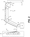
- Fig. 1 is a perspective illustration of an apparatus with which a measurement device 10 of embodiments of the present disclosure is contemplated to operate.
- a discussion of the apparatus is first provided.
- the present invention may encompass both the measurement device 10 and aspects of the apparatus as discussed herein.
- Fig. 1 illustrates a mold 12 onto which carbon fiber tows 14 are deposited to create a composite component 16.
- the component 16 is partially complete.
- the component 16 includes an opening 18 at a center thereof.
- the carbon fiber tows 14 are deposited in a manner that defines the opening 18 as layer upon layer of carbon fiber tows 14 are laid onto the surface 38 of the mold 12.
- the carbon fiber tows 14 are formed as prepreg tapes.
- a "prepreg” is a material where resin is pre-impregnated into the carbon fibers, but the resin is not yet cured.
- a prepreg therefore, may have an associated tackiness that helps the prepreg to stick to the surface 38 of the mold 12 or to previously-deposited layers of carbon fiber tows 14.
- the carbon fiber tows 14 are understood to define a width and a minimal thickness. Since the carbon fiber tows 14 are contemplated to include individual carbon fibers suspended in a resin that has not yet been cured, after all of the layers of the carbon fiber tows 14 are deposited on the mold 12 to form the composite component 16, the composite component 16 is cured 16 to form the final product. Typically, one or both of heat and pressure are applied to the carbon fiber tows 14 to cure the resin and create the final composite component 16.
- the carbon fiber tows 14 may have a predetermined width.
- the width of individual ones of the carbon fiber tows 14 is about 1 ⁇ 4 of an inch (about 6 mm).
- the present invention should not be understood to be limited solely to this particular width.
- Carbon fiber tows 14 of any suitable width may be employed.
- a fiber placement robot 20 (commonly referred to as an Advanced Fiber Placement "AFP" machine) deposits the carbon fiber tows 14 onto the mold 12 in parallel lines from a head 22 that contacts the surface 38 of the mold 12.
- the head 22 is connected to an articulated arm 24 secured on a base 26.
- Fig. 1 For the arrangement illustrated in Fig. 1 , it is contemplated that sixteen carbon fiber tows 14 are deposited simultaneously onto the surface 38 of the mold 12 in parallel. While the head 22 deposits sixteen carbon fiber tows 14 in each pass of the head 22 over the surface 38 of the mold 12, the present invention should not be understood to be limited to this construction. To the contrary, any number of carbon fiber tows 14 may be deposited by the head 22.
- the number of carbon fiber tows 14 that are deposited in each pass may differ from any other pass of the head 22 across the mold 12.
- the carbon fiber tows 14 are unraveled from spools 28 that are enclosed within a spool housing 30.
- the spool housing 30 provides a suitably stable environment to prevent the carbon fiber tows 14 from curing or partially curing prematurely. Moreover, the spool housing 30 helps to keep the carbon fiber tows 14 free from dust and contaminants before they are deposited onto the surface 38 of the mold 12.
- the carbon fiber tows 14 snake through one or more conduits 32 that extend from the spool housing 30 to the head 22 of the fiber placement robot 20.
- the conduits 32 not only direct the carbon fiber tows 14 to the head 22, the conduits 32 also help to keep the carbon fiber tows 14 free from dust and other contaminants. While two conduits 32 are shown, the apparatus may have any number of conduits 32, as required or desired.
- the fiber placement robot 20 may operate without reliance on a spool housing 30. Still further, the fiber placement robot 20 may be configured to operate without any conduits 32. For example, the spools 28 may be mounted directly onto the head 22. As should be apparent to those skilled in the art, the particular arrangement of components is not critical to operation of the present invention. The embodiments described herein are merely indicative of non-limiting examples.
- Fig. 2 is a graphical illustration of the apparatus illustrated in Fig. 1 .
- the conduit 32 includes a number of bends 34.
- the bends 34 provide a smooth transition around the joints 36 in the articulated arm 24, for example.
- the bends 34 are established dynamically by the shape and disposition of the articulated arm 24 as it moves to deposit the carbon fiber tows 14 onto the surface 38 of the mold 12.
- tension can build up within the carbon fiber tows 14. This may be due to the relatively long distance between the spool 28 and the head 22, as well as the various feeding mechanisms within the conduit 32 that enable the carbon fiber tows 14 to travel smoothly through the bends 34.
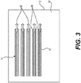
- Fig. 3 is an enlarged, graphical representation of a portion of the surface 38 of the mold 12 onto which the carbon fiber tows 14 are deposited. In this illustration, for simplicity, only five carbon fiber tows 14 are shown. Each of carbon fiber tows 14 include individual carbon fibers 40 that are grouped together, within an uncured resin, to form the carbon fiber tow 14.
- the carbon fiber tows 14 are deposited by the head 22 onto the surface 38 of the mold in the direction of the arrows 42. So that the individual carbon fiber tows 14 are distinguishable from one another in the illustrations, they are separated from one another by gaps 44. It should be understood, however, that the carbon fiber tows 14 are likely be laid next to one another with little or no gaps 44 between them.
- Fig. 4 illustrates the deposition of a first set of carbon fiber tows 46 and a second set of carbon fiber tows 48 separated from one another by a gap 50 that defines an opening, such as the opening 18 illustrated in Fig. 1 .
- the first set of carbon fiber tows 46 should terminate at a position within a given tolerance range and the second set of carbon fiber tows 48 should commence at a position within a given tolerance range.
- the head 22 presses the carbon fiber tows 14 against the mold starting at a first point 52.
- the head 22 travels to a second point 54, in the direction of the arrows 42, laying the first set of carbon fiber tows 46 onto the surface 38 of the mold 12.
- the tows 14 are cut, establishing the first side of the gap 50.
- the head 22 may be raised from the surface 38, as indicated by the arrow 56.
- the head 22 returns to the surface 38 at the third point 58, where the head 22 begins to lay the second set of carbon fiber tows 48 onto the surface 38.
- the head 22 continues until it reaches the fourth point 60, where the carbon fiber tows 14 are cut.
- the head 22 repeats this operation until all of the carbon fiber tows 14 are deposited onto the mold 12, in the order, at the angle, and to the thickness desired.
- the description of the operation of the head 22 is merely one, non-limiting example of many possible operations that may be performed by the fiber placement robot 20.
- the gap 50 may define any shape including, but not limited to, a square, a rectangle, a triangle, a polygon, a circle, an oval, an ellipse, or an amorphous shape, as required or as desired.
- the head 22 does not need to be lifted from the mold 12. Instead, the head 22 may cut and restart the application of the carbon fiber tows 14 while remaining pressed against the mold 12.
- the head 22 For the head 22 to precisely deposit the carbon fiber tows 14 onto the surface 38, it is desirable to control the tension in each of the carbon fiber tows 14 as they pass through the head 22 and are deposited onto the mold 12. More specifically, it is desirable to control the magnitude of the tension in the carbon fiber tows 14 at the point where the head 22 presses the carbon fiber tows 14 against the surface 38 of the mold 12. This point is referred to as the tip 62 of the head.
- uneven tension may develop in individual ones of the carbon fiber tows 14 during operation of the fiber placement robot 20. Uneven tension in the carbon fiber tows 14 is contemplated to impact the precision of the deposition onto the mold 12. Uneven tension can result in the carbon finer tows 14 being deposited at a position that is out-of-tolerance, or not deposited at all.
- One possible source of uneven tension may be a driver motor (not shown) responsible for feeding the carbon fiber tows 14 to the head 22 and onto the mold 12. It is contemplated that the driver motor may slip over one of the carbon fiber tows 14 having a high tension, because the driver motor is unable to overcome the high tension keeping the carbon fiber tow 14 in place. Alternatively, the driver motor may feed the carbon fiber tow 14 to the head 22 with a retard in one pass and without a retard in another pass.
- each subsequent set of carbon fiber tows 14 may be deposited unevenly.
- the total effect of these misalignments may require that the composite component 16 be rejected from service.
- the composite component 16 may have to be reworked and/or repaired by hand. In either case, a composite component 16 that is not manufactured according to specific guidelines, including uniform tension in the carbon fiber tows 14, is likely to result in a costly manufacturing process.
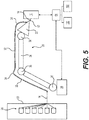
- Figs. 5-7 illustrate a measurement device 10 according to an embodiment of the present disclosure.
- While the tension in the carbon fiber tows 14 may be measured at any point along the length of the carbon fiber tows 14, the most useful measurements are taken at the tip 62 of the head 22, where the carbon fiber tows 14 are deposited onto the surface 38 of the mold 12. The further upstream from the head 22 the tension measurements are taken, the less suitable those measurements are for adjusting the operation of the fiber placement robot 20 and its associated equipment and components. It is desirable, therefore, to measure the tension in the carbon fiber tows 14 at or downstream of the tip 62 of the head 22.
- Fig. 5 illustrates the measurement device 10 in a position adjacent to the tip 62 of the head 22. In this view, all sixteen of the carbon fiber tows 14 are connected to the measurement device 10.
- the head 22 of the fiber placement robot 20 is moved to a predetermined location, as illustrated in Fig. 6 .
- the head 22 need not be the only part that is moved to the predetermined location.
- the arm 24 may be employed to move the head 22 to the predetermined location.
- the fiber placement robot 20 may be moved, in whole or in part.
- the tension in the individual tows 14 should be at a predetermined magnitude, arrived at by way of calculation, experimentation, and/or a combination of the two.
- the tension may be zero.
- the predetermined magnitude may be a tension value that should not be exceeded for the tension to be acceptable.
- any deviation from the predetermined magnitude may be assessed.
- the tension on individual ones of the carbon fiber tows 14 may be adjusted so that the tension is consistent with the predetermined magnitude. It is noted that the tension need not be the same for each carbon fiber tow 14.
- the tension in the carbon fiber tows 14 is the same at each discrete location along individual ones of the carbon fiber tows 14. Accordingly, the tension measured by the measurement device 10 is the tension that persists at the tip 62 of the head 22. As such, the measurement device 10 generates data that is very helpful when adjusting one or more components and/or variables associated with the apparatus.
- the measurement device 10 may be connected to a controller 64.
- the controller 64 may be connected, in turn, to the fiber placement robot 20 and any other equipment associated therewith.
- the controller 64 may be connected to the spools 28 via the spool housing 30.
- the controller 64 is contemplated to output a deviation signal indicative of whether one or more of the plurality of tension readings deviate from a predetermined tension value.
- the controller 64 is contemplated to adjust or cause the adjustment of one or more parameters associated with the operation of the fiber placement robot 20, the spools 28, the spool housing 30, etc., at least partly on the basis of the deviation signal.
- controller 64 The illustration and discussion of the controller 64 should not be understood to be limited to a single controller 64. It is contemplated that more than one controller 64 may be employed.
- the controller 64 may comprise a plurality of microcontrollers that are connected to load cells 74 in the measurement device 10, as discussed in greater detail below.
- the movement of the head 22 in relation to the measurement device 10 causes the generation of a plurality of measured tension readings, each of the plurality of measured tension readings being associated with a respective tension in each of the plurality of fiber tows 14.
- the controller 64 receives the plurality of measured tension readings and outputs one or more deviation signals indicative of whether one or more of the plurality of tension readings deviates from a predetermined tension value or range.
- movement of the robot 20 will result in the head 22 being moved with respect to the measurement device 10. It is equally possible that the measurement device 10 may be moved in relation to the head 22 to acquire the same measured tension values.
- Fig. 7 provides a perspective illustration of one contemplated embodiment of the measurement device 10.
- the measurement device 10 includes a housing 66 containing several load bars 68. While load bars 68 are employed in the illustrated example, load bars 68 should not be understood to limit the scope of the present invention. To the contrary, any suitable alternative may be employed.
- the load bars 68 are divided into an upper row of load bars 70 and a lower row of load bars 72. Since the measurement device 10 is contemplated to measure the tension in each of the sixteen carbon fiber tows 14 simultaneously, there are eight load bars 68 in the upper row of load bars 70 and eight load bars 68 in the lower row of load bars 72. The upper row of load bars 70 may be offset from the lower row of load bars 72 to provide additional room to attach the carbon fiber tows 14 thereto. It is understood that the measurement device 10 is not limited to 16 load bars 68 and that the measurement device 10 can have any number of load bars 68.
- each load bar 68 is contemplated to be connected to one load cell 74.
- the load bars 68 are contained within the housing 66.
- One such load cell 74 is illustrated in Fig. 7 .
- the load cells 74 generate the measured tension values in a manner known to those skilled in the art. It is noted that reliance on the load bars 68 is merely exemplary of the illustrated embodiment. Other suitable components may be employed to connect the carbon fiber tows 14 to the load cells 74.
- the load bars 68 are contemplated to be fitted with connectors 76.
- the connectors 76 are fashioned as hooks, a few of which are shown by way of example.
- One carbon fiber tow 14 is contemplated to be attached to each connector 76.
- the carbon fiber tows 14 may be provided with openings 78 to engage the connectors 76.
- the carbon fiber tows 14 may be tied to the connectors 76.
- the carbon fiber tows 14 may be affixed to the connectors 76 using adhesive tape or any other suitable fastener.
- the connectors 76 may be pulleys or eyelets, for example, through which the carbon fiber tows 14 pass before being deposited onto the mold 12.
- the measurement device 10 may take periodic measurements of the tension in the carbon fiber tows 14, for example.
- the fiber placement robot 20 is moved such that the head 22 of the robot moves in relation to the measurement device 10 so that the tension in each of the carbon fiber tows 14 may be measured.
- the load bars 68 are provided with holes 80, which help the load bars 68 to flex. The strain on the load bars 68 may then be translated, by the load cells 74, into a measured tension in the carbon fiber tows 14.
- Fig. 8 is a flowchart that illustrates one non-limiting method 82 for measuring the tension in a plurality of carbon fiber tows 14.
- the method 82 starts at step 84.
- the method 82 proceeds to step 86 where the plurality of carbon fiber tows 14 are attached to the connectors 76 on the measurement device 10. This is illustrated, for example, in Fig. 5 .
- the method 82 then proceeds to step 88.
- the carbon fiber tows 14 may be connected to the connectors 76 on a permanent or semi-permanent basis.
- step 88 the fiber placement robot 20 is reconfigured to a predetermined position, such as shown in Fig. 6 . At this predetermined position, a predetermined tension is anticipated to persist in each of the carbon fiber tows 14 for desirable operation of the apparatus.
- the method 82 then proceeds to step 90.
- step 88 may be omitted and the method 82 may commence at step 90.
- a plurality of measured tension readings are obtained by the measurement device 10.
- the measured tension values are generated by the load cells 74.
- Each of the plurality of measured tension readings are associated with a respective tension in each of the plurality of carbon fiber tows 14. The method 82 then proceeds to step 92.
- the measured tension value is compared to the predetermined tension value. This may be done by the measurement device 10, the controller 64, or another device, for example. The method 82 then proceeds to step 94.
- a deviation between the measured tension value and the predetermined tension value is determined.
- the deviation leads to the outputting of a deviation signal indicative of a deviation between the measured tension readings and the predetermined tension value. This may be done by the measurement device 10, the controller 64, or another device, for example.
- the deviation signal is indicative of whether one or more of the plurality of measured tension readings deviates from the predetermined value. The method 82 then proceeds to step 96.
- the method 82 causes adjustment of operational parameters of the fiber placement robot 20.
- one or more parameters associated with the operation of the fiber placement robot 20, the spool housing 30, the conduit 32, and/or the head 22, may be caused to be adjusted in response to the generating of the deviation signal.
- Still other parameters may be adjusted and/or caused to be adjusted.
- causing adjustment is contemplated to include displaying tension deviation readings, displaying a suggested parameter adjustment, automatically implementing some sort of adjustment, causing a shutdown of the fiber placement robot 20, etc.
- the measurement device 10, the controller 64, and/or another device may be responsible for causing the adjustment of the parameter or parameters.
- the method 82 then proceeds to step 98.
- the method 82 ends at step 98.
- the tension that is measured at step 90 may or may not comport with the predetermined tension. Any deviation between the measured tension and the predetermined tension may then be adjusted by altering one or more of the parameters associated with the apparatus.
- the controller 64 may comprise a plurality of microcontrollers. If so, it is contemplated that each of the plurality of microcontrollers will be connected to and/or associated with one of the plurality of load cells 74. Still further, one microcontrollers may be connected with several load cells 74.
- the load cells 74 and associated controller 64 output a signal indicative of whether one or more of the tension readings is out of tolerance.
- the term “deviation” is used to refer to a tension reading that is out of tolerance, deviates from or exceeds a predetermined value or range.
- the measured tension and/or the deviation may be displayed on a display 100.
- a display 100 may be a computer screen, for example.
- the display 100 should not be understood to be limited solely to a computer screen. It is contemplated that the display 100 may be as simple as a single light source that is illuminated when the deviation is greater than a predetermined value. As should be apparent to those skilled in the art, there are numerous ways in which the deviation may be displayed to a user.
- Outputting a signal indicative of whether one or more of the plurality of tension readings is out of tolerance may encompass the display a visual indication of an out-of-tolerance condition.
- a warning light may be employed to provide the visual indication.
- controller 64 is contemplated to determine if one or more of the plurality of measured tension readings is out of tolerance (and, therefore, a deviation) by comparing each of the plurality of measured tension readings to a predetermined acceptable tension value for each carbon fiber tow 14.
- the controller 64 may be connected to a non-transient machine-readable memory unit 102 for storing the plurality of measured tension readings and predetermined acceptable tension values for each of the carbon fiber tows 14.
- the machine-readable memory unit 102 also may be configured to record each deviation so that the signals indicative of whether one or more of the plurality of measured tension readings is out of tolerance may be analyzed, as required or desired.
- the measurement device 10 may be integrated into the fiber placement robot 20 so that the measurement device 10 may measure the tension in the carbon fiber tows 14 when prompted by an operator.
- the measurement device 10 may be configured to measure the tension in the carbon fiber tows 14 at periodic intervals (i.e., every fifteen minutes) during operation of the fiber placement robot 20, after the measurement device 10 is connected to the carbon fiber tows 14.
- the measurement device 10 may be integrated into the head 22 of the fiber placement robot 22.
- the measurement device 10 may take periodic measurements of the tension in the carbon fiber tows 14. Those measurements may be recorded as tension data in a memory connected to the controller 64 in one non-limiting example. When plural measurements are recorded over a period of time, the tension data may be analyzed for diagnostic and/or prognostic purposes, for example.
- the controller 64 may incorporate logic that correlates the tension data and any tension deviation with events during the motion of the fiber placement robot 20 that might be responsible for those tension deviations.
- tension deviations may result in adjustment of one or more operating parameters of the fiber placement robot 20 and associated equipment.
- the tension deviation may indicate that a conduit 32 requires replacement.
- a feeding device may be the source of the deviation.
- a spool may be responsible for the deviation, etc.
- the deviation signal is contemplated to encompass a wide variety of different signals and should not be understood to be limited solely to a signal representative of a particular tension measurement.
- the deviation signal may be associated with a minimum and/or maximum value. If so, the deviation signal may be generated under conditions when the measured tension meets or exceeds the minimum or maximum values.
- the deviation signal may be an alarm that may be visual, auditory, audio-visual, or the like.
- the deviation signal may encompass a mean value and/or a peak value.
- the deviation signal also may be the amount a reading deviates from a predetermined tension value.
- the deviation signal may encompass other suitable information and values.
Landscapes
- Engineering & Computer Science (AREA)
- Chemical & Material Sciences (AREA)
- Mechanical Engineering (AREA)
- Materials Engineering (AREA)
- Physics & Mathematics (AREA)
- Manufacturing & Machinery (AREA)
- Composite Materials (AREA)
- Robotics (AREA)
- General Physics & Mathematics (AREA)
- Analytical Chemistry (AREA)
- Optics & Photonics (AREA)
- Textile Engineering (AREA)
- Moulding By Coating Moulds (AREA)
Applications Claiming Priority (1)
| Application Number | Priority Date | Filing Date | Title |
|---|---|---|---|
| US201862675928P | 2018-05-24 | 2018-05-24 |
Publications (1)
| Publication Number | Publication Date |
|---|---|
| EP3572216A1 true EP3572216A1 (fr) | 2019-11-27 |
Family
ID=66776086
Family Applications (1)
| Application Number | Title | Priority Date | Filing Date |
|---|---|---|---|
| EP19176047.9A Withdrawn EP3572216A1 (fr) | 2018-05-24 | 2019-05-22 | Dispositif de mesure et procédé de mesure de la tension de mèches en fibre de carbone |
Country Status (2)
| Country | Link |
|---|---|
| US (1) | US20190358916A1 (fr) |
| EP (1) | EP3572216A1 (fr) |
Cited By (1)
| Publication number | Priority date | Publication date | Assignee | Title |
|---|---|---|---|---|
| EP3862173A1 (fr) * | 2020-02-05 | 2021-08-11 | Tsudakoma Kogyo Kabushiki Kaisha | Appareil de placement automatisé de faisceau de fibres |
Families Citing this family (2)
| Publication number | Priority date | Publication date | Assignee | Title |
|---|---|---|---|---|
| DE102020114894A1 (de) | 2020-06-04 | 2021-12-09 | Broetje-Automation Gmbh | Vorrichtung zur Verarbeitung von faserverstärktem Kunststoff |
| CN112161738B (zh) * | 2020-09-17 | 2022-04-08 | 五邑大学 | 气压传感器及制作方法 |
Citations (5)
| Publication number | Priority date | Publication date | Assignee | Title |
|---|---|---|---|---|
| US5766357A (en) * | 1996-09-19 | 1998-06-16 | Alliant Techsystems Inc. | Apparatus for fiber impregnation |
| GB2471319A (en) * | 2009-06-26 | 2010-12-29 | Hexcel Composites Ltd | Manufacturing composite materials containing conductive fibres |
| CN105690801A (zh) * | 2016-04-13 | 2016-06-22 | 李军利 | 一种碳纤维复合材料自动铺丝通用铺放装置 |
| EP3141378A2 (fr) * | 2015-08-12 | 2017-03-15 | General Electric Company | Système et procédé de commande d'au moins une variable au cours d'une superposition de pièce composite au moyen de positionnement de fibre automatisé |
| US9636903B2 (en) * | 2014-05-14 | 2017-05-02 | Tsudakoma Kogyo Kabushiki Kaisha | Lay-up-position correcting method for automatic lay-up machine |
Family Cites Families (1)
| Publication number | Priority date | Publication date | Assignee | Title |
|---|---|---|---|---|
| US6491773B1 (en) * | 2000-01-24 | 2002-12-10 | Alliant Techsystems Inc. | Position-controlled tensioner system |
-
2019
- 2019-05-22 EP EP19176047.9A patent/EP3572216A1/fr not_active Withdrawn
- 2019-05-22 US US16/419,803 patent/US20190358916A1/en not_active Abandoned
Patent Citations (5)
| Publication number | Priority date | Publication date | Assignee | Title |
|---|---|---|---|---|
| US5766357A (en) * | 1996-09-19 | 1998-06-16 | Alliant Techsystems Inc. | Apparatus for fiber impregnation |
| GB2471319A (en) * | 2009-06-26 | 2010-12-29 | Hexcel Composites Ltd | Manufacturing composite materials containing conductive fibres |
| US9636903B2 (en) * | 2014-05-14 | 2017-05-02 | Tsudakoma Kogyo Kabushiki Kaisha | Lay-up-position correcting method for automatic lay-up machine |
| EP3141378A2 (fr) * | 2015-08-12 | 2017-03-15 | General Electric Company | Système et procédé de commande d'au moins une variable au cours d'une superposition de pièce composite au moyen de positionnement de fibre automatisé |
| CN105690801A (zh) * | 2016-04-13 | 2016-06-22 | 李军利 | 一种碳纤维复合材料自动铺丝通用铺放装置 |
Cited By (1)
| Publication number | Priority date | Publication date | Assignee | Title |
|---|---|---|---|---|
| EP3862173A1 (fr) * | 2020-02-05 | 2021-08-11 | Tsudakoma Kogyo Kabushiki Kaisha | Appareil de placement automatisé de faisceau de fibres |
Also Published As
| Publication number | Publication date |
|---|---|
| US20190358916A1 (en) | 2019-11-28 |
Similar Documents
| Publication | Publication Date | Title |
|---|---|---|
| EP3572216A1 (fr) | Dispositif de mesure et procédé de mesure de la tension de mèches en fibre de carbone | |
| US8753458B2 (en) | Mapping tow splices in composite structures | |
| US9694546B2 (en) | Automated fiber placement compensation | |
| Nguyen et al. | Effect of automated fiber placement (AFP) manufacturing signature on mechanical performance of composite structures | |
| US11760030B2 (en) | Systems and methods for controlling additive manufacturing | |
| US7807002B2 (en) | Verification of tow cut for automatic fiber placement | |
| JP4266437B2 (ja) | ファイバ部材の複合構造の製造装置および製造方法 | |
| EP1810816B1 (fr) | Contrôle visuel de l'emplacement de fibres | |
| EP2077447B1 (fr) | Système et procédé pour déterminer la largeur de fente de remorquage cumulatif | |
| KR100967494B1 (ko) | 복합재료 물품을 제조하는 장치 | |
| CN107436590B (zh) | 由机器人铺放的丝束的检查 | |
| US20050163414A1 (en) | Rib structural system and method of manufacturing the rib structural system | |
| DE102017212068A1 (de) | Faserverbund-Ablegevorrichtung und Faserverbund-Ablegeverfahren zur Herstellung eines Faserverbundgeleges für die Bildung eines Faserverbundbauteils | |
| EP3599457A1 (fr) | Caractérisation des rapports de brins de voile fondus dans des couches de matériau fibreux | |
| Ebel et al. | Yarn damage during braiding of reinforcement fibers for composites | |
| EP4035875B1 (fr) | Procédé pour déterminer l'énergie de décollement d'un stratifié composite | |
| Assi et al. | Design and characterization of an active spool tensioner for braiding machines | |
| Böckl | Evaluation and documentation of manufacturing defects in Automated Fiber Placement | |
| Ferguson | A Manufacturing Study of Thin-Ply Composite Prepregs in Automated Fiber Placement (AFP) for Aerospace Structures | |
| Morabito et al. | Continuously extruded wrapped tow reinforced truss beams | |
| US20260110535A1 (en) | Monitoring of buffer tube shrinkage during fiber optic cable manufacturing | |
| JP6935726B2 (ja) | 識別糸付着位置の制御装置 | |
| EP4494855A1 (fr) | Système et procédés de stratification composite | |
| Maidl | Integrated Sensor System for Monitoring the Braiding Process as a Use Case for Digitalization in Composite Production Technology | |
| CN120921738A (zh) | 一种用于露天煤场覆膜的制造和牵引固定方法 |
Legal Events
| Date | Code | Title | Description |
|---|---|---|---|
| STAA | Information on the status of an ep patent application or granted ep patent |
Free format text: STATUS: UNKNOWN |
|
| PUAI | Public reference made under article 153(3) epc to a published international application that has entered the european phase |
Free format text: ORIGINAL CODE: 0009012 |
|
| STAA | Information on the status of an ep patent application or granted ep patent |
Free format text: STATUS: THE APPLICATION HAS BEEN PUBLISHED |
|
| AK | Designated contracting states |
Kind code of ref document: A1 Designated state(s): AL AT BE BG CH CY CZ DE DK EE ES FI FR GB GR HR HU IE IS IT LI LT LU LV MC MK MT NL NO PL PT RO RS SE SI SK SM TR |
|
| AX | Request for extension of the european patent |
Extension state: BA ME |
|
| STAA | Information on the status of an ep patent application or granted ep patent |
Free format text: STATUS: REQUEST FOR EXAMINATION WAS MADE |
|
| 17P | Request for examination filed |
Effective date: 20200601 |
|
| RBV | Designated contracting states (corrected) |
Designated state(s): AL AT BE BG CH CY CZ DE DK EE ES FI FR GB GR HR HU IE IS IT LI LT LU LV MC MK MT NL NO PL PT RO RS SE SI SK SM TR |
|
| STAA | Information on the status of an ep patent application or granted ep patent |
Free format text: STATUS: THE APPLICATION IS DEEMED TO BE WITHDRAWN |
|
| 18D | Application deemed to be withdrawn |
Effective date: 20211201 |