EP3572297A1 - Schubkarre mit kippschale - Google Patents
Schubkarre mit kippschale Download PDFInfo
- Publication number
- EP3572297A1 EP3572297A1 EP19175412.6A EP19175412A EP3572297A1 EP 3572297 A1 EP3572297 A1 EP 3572297A1 EP 19175412 A EP19175412 A EP 19175412A EP 3572297 A1 EP3572297 A1 EP 3572297A1
- Authority
- EP
- European Patent Office
- Prior art keywords
- tray
- wheelbarrow
- chassis
- pivot axis
- wheel
- Prior art date
- Legal status (The legal status is an assumption and is not a legal conclusion. Google has not performed a legal analysis and makes no representation as to the accuracy of the status listed.)
- Granted
Links
Images



Classifications
-
- B—PERFORMING OPERATIONS; TRANSPORTING
- B62—LAND VEHICLES FOR TRAVELLING OTHERWISE THAN ON RAILS
- B62B—HAND-PROPELLED VEHICLES, e.g. HAND CARTS OR PERAMBULATORS; SLEDGES
- B62B1/00—Hand carts having only one axis carrying one or more transport wheels; Equipment therefor
- B62B1/18—Hand carts having only one axis carrying one or more transport wheels; Equipment therefor in which the load is disposed between the wheel axis and the handles, e.g. wheelbarrows
- B62B1/24—Hand carts having only one axis carrying one or more transport wheels; Equipment therefor in which the load is disposed between the wheel axis and the handles, e.g. wheelbarrows involving tiltably-mounted containers
Definitions
- the invention relates to a wheelbarrow according to the introductory portion of claim 1.
- a wheelbarrow is known from U.S. patent 2 482 608 and from German patent application 1 724 687 .
- the tray is pivotable relative to a chassis about a pivot axis forward of the axis of rotation of the wheels.
- the tray can be caused to tip up further by tilting the chassis backward about the axis of rotation of the wheels.
- a load can be dumped from the tray very easily. Initially the tray is tipped up by tilting the whole wheelbarrow forward and subsequently the tray is tipped further by tilting the chassis of the wheelbarrow backward again.
- the second stage of tipping up is not achieved reliably, the tipping angle of the second stage is limited and/or a large force has to be exerted to achieve the second stage of tipping.
- tipping the wheelbarrow back to its transport or rest position with the tray in its load carrying position cannot reliably be achieved by just tilting the chassis backward again.
- this object is achieved by providing a wheelbarrow according to claim 1.
- the invention can also be embodied in methods according to claim 10 and 11 of using such a wheelbarrow.
- the tray is provided with a guide for allowing guided displacement of the pivot axis along the tray between a first position and a second position, the pivot axis being in the first position if the tray is in the load carrying position and the second position is rearward from the first position, the pivot axis can be displaced relative to the center of gravity of the tray and any load held therein. This allows reliably effecting either forward or backward tilting of the tray by vertical movement of the pivot axis, regardless whether or to what extent initial tipping of the tray has resulted in displacement of the load and, accordingly, of its center of gravity.
- the chassis can project relatively far forward from the axis of rotation of the wheel or wheels towards the pivot axis, so that a relatively small amount of tilting of the chassis about the axis of rotation of the wheel or wheels can result in a substantial amount of tilting of the tray.
- This also allows the chassis to extend at a relatively low level above the ground, so that the center of gravity of the wheelbarrow in transport position can be relatively low and preventing undesired tipping of the wheelbarrow requires relatively little effort.
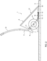
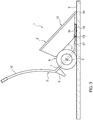
- a wheelbarrow 1 is shown in four consecutive stages of operation during dumping of a load 2 (shown in Fig. 1 only).
- the wheelbarrow 1 has a chassis 3 to which wheels 4 are mounted for rotation of the wheels 4 about a center line 5 of the wheels 4, which center line thus constitutes the axis of rotation of the wheels 4.
- the wheels 4 are thus suspended to allow rolling of the wheels 4 over a ground surface 6 while supporting the chassis 3 spaced from the ground surface 6.
- the chassis 3 has a tray support portion 7, on which a tray 8 of the wheelbarrow 1 rests when in a load carrying position relative to the chassis 3.
- the chassis 3 further has support legs 9. If the wheelbarrow 1 is in a rest position as shown in Fig. 1 , the support legs 2 are rearward of the wheels 4 and extend downwardly for resting on the ground 6 supporting the wheelbarrow 1 rearward of the wheels 4. If the wheelbarrow 1 is in a transport position, which allows rolling the wheelbarrow 1 without the support legs 9 dragging over the ground 6, the support legs 9 are also rearward of the wheels 4 but the wheelbarrow 1 is tilted slightly about the axis of rotation 5 so that the support legs are spaced from the ground 6.
- the chassis 3 may also have a single support leg or more than two support legs. If a single support leg is provided, it is advantageous for stability of the wheelbarrow 1 in its rest position, if the support leg has a foot of a substantial width in a direction transverse to the forward and rearward rolling directions of the wheel or wheels.
- the chassis 3 further has handlebars 10 which project in a direction rearward and upward from the tray support portion 7 if the wheelbarrow 1 is in the transport position.
- the tray 8 has a bottom 11 and an open top 12 for loading material to be transported into the tray 8 and dumping the transported material from the tray 8.
- a removable lid may be provided for closing off the tray 8.
- the tray 8 is coupled to the chassis 3 so as to be pivotable relative to the chassis 3 about a pivot axis 13 forwardly of the center line 5 of the wheels 4, from a load carrying position in which the bottom 11 is closely adjacent to the tray support portion 7 of the chassis 3 (see Figs. 1 and 2 ) to a dumping position in which the bottom 11 is pivoted away from the tray support portion 7 of the chassis 3 for the dumping of the transported material (see Fig. 4 ).
- the pivot axis is located forwardly of the wheels 4, which is advantageous for increasing lever arm length of the chassis 3 forwardly of the axis of rotation 5 of the wheels 4.
- the tray 8 is further provided with a guide 14 for allowing guided displacement of the pivot axis 13 along the tray 8 between a first position ( Figs. 1 and 2 ) and a second position ( Figs. 3 and 4 ).
- the pivot axis 13 is in the first position if the tray 8 is in the load carrying position.
- the second position of the pivot axis 13' is more rearward relative to the tray 8 than the first position of the pivot axis 13.
- a load of bulk material 2 or one or more items loaded into the tray 8 can be transported to location where the bulk material 2 is to be dumped.
- the wheelbarrow 1 is held in the transport position, which is slightly tilted forward compared with the rest position shown in Fig. 1 .
- the wheels 4 resting on the ground surface 6 the handle bars 10 are held by a user and the tray 8 is in the load carrying position shown in Figs. 1 and 2 .
- the wheelbarrow 1 When the destination of the transported load has been reached, the wheelbarrow 1 is tilted forward about the axis of rotation 5 of the wheels 4 by lifting the handle bars 10, preferably until a front end 15 of the wheelbarrow 1 abuts against the ground surface 6, so that a position as shown in Fig. 2 is reached. If an item, e.g. a newborn calf, is transported, it can be shifted out of the tray 8 in this position. However, in this position, the tray 8 is tipped over to some extent, but not enough to dump all bulk material 2 out of the tray 8.
- the chassis 3 is rolled backward causing the pivot axis 13 to move from the first position 13 to the second position 13', so that a position as shown in Fig. 3 is reached.
- the tray 8 will not move backward with the chassis 3, because the front end of the tray 8 rests on the ground 6, so that no special measures for preventing the tray 8 from moving backward with the chassis are required.
- the pivot axis 13' can be displaced relative to the center of gravity of the tray 8 and any load 2 held therein. This allows reliably effecting either forward or backward tilting of the tray 8 by vertical movement of the pivot axis 13, regardless whether or to what extent initial tipping of the tray 8 has resulted in displacement of the load 2 and accordingly its center of gravity. If the pivot axis 13 is in the forward first position, the tray 8 will reliably tilt in unison with the chassis 3. In contrast, if the pivot axis 13 is in the rearward second position, the tray 8 will reliably tilt in a sense opposite to the sense in which the chassis 3 is tilted.
- initial tipping of the tray 8 with the chassis 3 from a transport position and tipping back of the chassis 3 with the tray 8 to a transport position is reliably controlled by tilting the handle bars 10 with the pivot axis in the first position and subsequent tipping of the tray for emptying and tipping back after emptying is reliably controlled by tilting the handle bars 10 with the pivot axis 13 in the second position.
- the chassis 3 can be dimensioned to project relatively far forward from the axis of rotation 5 of the wheels towards the pivot axis 13, so that a relatively small amount of tilting of the chassis 3 about the axis of rotation 5 of the wheels is sufficient for obtaining a substantial amount of tipping of the tray 8 during the subsequent stage of tipping. Also, because little ground clearance is needed for allowing tilting of the chassis, the chassis 3 can be dimensioned to extend at a relatively low level above the ground 6, so that the center of gravity of the wheelbarrow 1 in transport position can be relatively low. Preventing undesired tipping of the wheelbarrow 1 then requires relatively little effort.
- a wheelbarrow Also collecting and then transporting items or bulk material is facilitated by a wheelbarrow according to the invention.
- Bulk material or an item such as a newborn calf, can be loaded into the tray particularly easily if the tray 8 is tilted away from the tray support portion 7 of the chassis 3 with the forward end wall 16 extending substantially horizontally along the ground surface 6.
- the item or bulk material does not have to be lifted more than over the thickness of the upper end of the forward end wall 16 to transfer it from the ground surface 6 into the tray 8. More in particular, the item or bulk material can generally be shoved from the ground surface 6 into the tray 8 and bulk material can also be swept into the tray.
- the pivot axis 13 is moved from the second position to the first position.
- backward tilting of the chassis 3 about the axis of rotation 5 of the wheels 4 by urging the handle bars 10 downwards until the wheelbarrow 1 is in the transport position reliably results in tipping back the tray 8 in unison with the chassis 3.
- tipping back the tray 8 into an upright position after one or more items or bulk material has been loaded into the tray 8 in a forward tipped position can easily be carried out by operating the handle bars 10 and no separate operation of tipping back the tray 8 is required.
- the second position is also downward from the first position.
- This allows moving the pivot axis between the first and second positions, while the tray is in the forward tipped position, with relatively little tilting of the chassis.
- such an inclined orientation of the guide trajectory along which the pivot axis is guided ensures that the pivot axis reliably stays in the first position if the wheelbarrow is in the transport position, even when riding over bumps or suddenly accelerating or decelerating.
- the forward end wall 16 of the tray 8 extends outwardly inclined from its bottom end to its top end. Because forward end wall 16 is outwardly inclined tipping over a relatively small angle is sufficient for tipping the tray 8 between, on the one hand, an upright position and, on the other hand, a sloping position for dumping bulk material or a position about parallel to the ground surface 6 for easy loading of one or more items or bulk material.
- the forward end wall 16 is inclined and positioned such that, seen in side view, a downward continuation of an outer surface of the forward end wall 16 extends closely along an outer circumference of the wheels 4.
- the forward end wall 16 is parallel to the ground surface 6, which facilitates loading of one or more items or bulk material into the tray 8.
- the guide and the tray this may involve a slight tilting of the chassis, but in the wheelbarrow according to the present example tilting of the chassis is not required for bringing the tray 8 into the load carrying position relative to the chassis 3, because the guide 14 for allowing guided displacement of the pivot axis 13 extends substantially parallel to the forward end wall 16.
- the guide 14 for allowing guided displacement of the pivot axis 13 is mounted to outside of the forward end wall 16
- the guide 14 can be mounted to the tray 8 in a simple manner and a robust support for the forward end wall 16 is provided.
- the chassis 3 has a front end 17 extending to the pivot axis 13 along the outside of the forward end wall 16 when the tray 8 is in its transport position.
- the wheelbarrow 1 has two wheels 4 on opposite sides of the tray 8 and the chassis 3 and rotatable about a common axis of rotation 5. This is advantageous for stability when navigating the wheelbarrow 1, in particular when transporting a heavy load 2 and allows the provision of large wheels without accordingly raising the ride height of the tray 8 above the ground 6.
- a wheelbarrow may also be provided with a single wheel only or with more than two wheels, e.g. additional wheels at lower ends of the support legs wheels and/or additional wheels between the front wheels for reducing track formation in soft ground.
- the guides 64 for allowing guided displacement of the pivot axis 63 along the tray 58 is in the form of a pair of webs 69 each extending in a longitudinal direction along the forward end wall 66 of the tray 58 and each projecting transversely (in this example perpendicularly) from the forward end wall 66 of the tray 58.
- a guide slot 70 is provided in which a pivot member 71 of the chassis 53 is received.
- the pivot member is a bar 71 oriented parallel to the axis of rotation 55 of the wheels 54.
- other forms of pivot members such as knobs projecting through the slot with heads or flanges for keeping the knobs in engagement with the webs, are also conceivable.
- the webs 69 are integrally formed with the tray 58. It is however also possible to provide the webs in the form of a web of a profile mounted to the tray, for instance by fasteners and/or by locking engagement with engagement portions on the outside of the forward end wall of the tray.
- the slots 70 for guiding displacement of the pivot axis 63 along the tray 58 extend substantially parallel to the forward end wall 66.
- the guide slots 70 substantially parallel to the forward end wall 66 can be oriented at a slight angle of preferably less than 10° relative to the forward end wall 66. In order of increasing preference, this angle is smaller than 8° or 6° and for instance 4° as in the present example.
- anti-pivot guides 72 project from the webs 69 at the sides of the webs where the pivot members 71 and front end arms 67 of the chassis 53 extending to the pivot members 71 are located.
- the anti-pivot guides 72 preferably end in downward and backward direction at approximately 10 to 30 % of the length of the guides 64 so as to engage the pivot member 71 or the front end arms 67 of the chassis 53 unless the pivot axis 63 has been moved nearly completely towards rearward and bottom ends of the guide slots 70.
- the anti-pivot guides prevent the tray 58 from tilting forwardly relative to chassis 53 unless the pivot axis 63 has been moved nearly completely towards the rearward and bottom ends of the guide slots 70.
- the anti-pivot guides are provided in the form of flanges 72 that each extend from near the lower bottom end of the associated guide slot 72 to the upper forward end of the associated guide slot 70.
- the flanges 72 keep the pivot members 71 clear from a ground surface on which wheelbarrow rests if the wheelbarrow is tilted forward. This avoids jamming of the pivot member 71 against terrain bumps or obstacles like stones on the ground when shifting the chassis 53 relative to a forwardly tilted tray 58, in particular when shifting the chassis 53 from the rearward position as shown in Fig. 3 to the forward position as shown in Fig. 2 .
- supports 73 project beyond a lower rearward end of the forward end wall 66. These supports 73 counteract rearward tilting of the tray 58 when it is being filled while resting on a ground surface in a forwardly tilted orientation with the chassis rearwardly retracted as shown in Fig. 3 .
- the guide slots 70 are provided with notches 74, 75 shaped and dimensioned for at least partially receiving at least the pivot member 71. Because the slots 71 are each provided with two of these notches, the pivot member 71 can be held in two different positions in the slots 70 during tilting, for allowing a choice between, in a light load discharging mode, quick tilting over a large angle or, in a heavy load discharging mode, slower tilting over a smaller angle requiring less force to be exerted on the chassis 53 than tilting in the light load mode.
Landscapes
- Engineering & Computer Science (AREA)
- Chemical & Material Sciences (AREA)
- Combustion & Propulsion (AREA)
- Transportation (AREA)
- Mechanical Engineering (AREA)
- Handcart (AREA)
Applications Claiming Priority (1)
| Application Number | Priority Date | Filing Date | Title |
|---|---|---|---|
| NL2020961A NL2020961B9 (en) | 2018-05-18 | 2018-05-18 | Wheelbarrow with tip up tray |
Publications (2)
| Publication Number | Publication Date |
|---|---|
| EP3572297A1 true EP3572297A1 (de) | 2019-11-27 |
| EP3572297B1 EP3572297B1 (de) | 2022-04-27 |
Family
ID=64744891
Family Applications (1)
| Application Number | Title | Priority Date | Filing Date |
|---|---|---|---|
| EP19175412.6A Active EP3572297B1 (de) | 2018-05-18 | 2019-05-20 | Schubkarre mit kippschale |
Country Status (2)
| Country | Link |
|---|---|
| EP (1) | EP3572297B1 (de) |
| NL (1) | NL2020961B9 (de) |
Citations (7)
| Publication number | Priority date | Publication date | Assignee | Title |
|---|---|---|---|---|
| US1727271A (en) * | 1928-10-08 | 1929-09-03 | Burns John | Wheelbarrow |
| US1804404A (en) * | 1929-04-13 | 1931-05-12 | Francis J Dowling | Wheeled carrier |
| US1804403A (en) * | 1928-03-05 | 1931-05-12 | Francis J Dowling | Loading wheelbarrow |
| US2037222A (en) * | 1935-09-03 | 1936-04-14 | Ogden S Farrar | Automatic dumping wheelbarrow |
| US2482608A (en) | 1945-01-24 | 1949-09-20 | Antonia Rea | Dumpcart |
| DE1724687U (de) | 1956-03-24 | 1956-06-21 | Willy Braun | Kippkarre. |
| US20130062844A1 (en) * | 2011-09-12 | 2013-03-14 | George W. Stevens | Wheelbarrow Configuration |
-
2018
- 2018-05-18 NL NL2020961A patent/NL2020961B9/en not_active IP Right Cessation
-
2019
- 2019-05-20 EP EP19175412.6A patent/EP3572297B1/de active Active
Patent Citations (7)
| Publication number | Priority date | Publication date | Assignee | Title |
|---|---|---|---|---|
| US1804403A (en) * | 1928-03-05 | 1931-05-12 | Francis J Dowling | Loading wheelbarrow |
| US1727271A (en) * | 1928-10-08 | 1929-09-03 | Burns John | Wheelbarrow |
| US1804404A (en) * | 1929-04-13 | 1931-05-12 | Francis J Dowling | Wheeled carrier |
| US2037222A (en) * | 1935-09-03 | 1936-04-14 | Ogden S Farrar | Automatic dumping wheelbarrow |
| US2482608A (en) | 1945-01-24 | 1949-09-20 | Antonia Rea | Dumpcart |
| DE1724687U (de) | 1956-03-24 | 1956-06-21 | Willy Braun | Kippkarre. |
| US20130062844A1 (en) * | 2011-09-12 | 2013-03-14 | George W. Stevens | Wheelbarrow Configuration |
Also Published As
| Publication number | Publication date |
|---|---|
| EP3572297B1 (de) | 2022-04-27 |
| NL2020961B9 (en) | 2019-12-18 |
| NL2020961B1 (en) | 2019-11-25 |
Similar Documents
| Publication | Publication Date | Title |
|---|---|---|
| CA2513748C (en) | Easy dumping cart | |
| EP0889818B1 (de) | Umwandelbarer schubwagen zum laden am bodenniveau | |
| US4921305A (en) | Wheel barrow | |
| US20060119164A1 (en) | Tipping mechanism | |
| US6715980B2 (en) | Tiltable container | |
| US20020113389A1 (en) | Tipping wheelbarrow | |
| US7438300B1 (en) | Hand truck with pivotal retainer | |
| US4068751A (en) | Gravity feed-return pallet storage rack | |
| US3160439A (en) | Hand dump truck | |
| EP3572297B1 (de) | Schubkarre mit kippschale | |
| US11859358B2 (en) | Sleigh shovel | |
| US3233764A (en) | Transporting devices | |
| US2240585A (en) | Wheelbarrow | |
| US4403901A (en) | Dump bin | |
| EP1212229B1 (de) | Schaufelhandwagen ausgerüstet mit einer abschieberplatte zum abschieben von lasten von der schaufel | |
| GB2360511A (en) | Self emptying container | |
| EP3081716A1 (de) | Liegender betonkübel, dessen untergestell eine wiederaufnahme dieses kübels mit der gabel eines gabelstaplers ermöglicht | |
| US20070176380A1 (en) | Convertible barrow for ground level loading | |
| NL2019100B1 (nl) | Kruiwagen | |
| US4057161A (en) | Lifting and handling apparatus | |
| CA2557021A1 (en) | Convertible barrow for ground level loading | |
| GB2372238A (en) | Tipping wheelbarrow | |
| GB2342073A (en) | Wheelbarrow with suspension | |
| JP2008162469A (ja) | 運搬用具 | |
| GB2366771A (en) | Wheelbarrow with endless track unit |
Legal Events
| Date | Code | Title | Description |
|---|---|---|---|
| PUAI | Public reference made under article 153(3) epc to a published international application that has entered the european phase |
Free format text: ORIGINAL CODE: 0009012 |
|
| STAA | Information on the status of an ep patent application or granted ep patent |
Free format text: STATUS: THE APPLICATION HAS BEEN PUBLISHED |
|
| AK | Designated contracting states |
Kind code of ref document: A1 Designated state(s): AL AT BE BG CH CY CZ DE DK EE ES FI FR GB GR HR HU IE IS IT LI LT LU LV MC MK MT NL NO PL PT RO RS SE SI SK SM TR |
|
| AX | Request for extension of the european patent |
Extension state: BA ME |
|
| STAA | Information on the status of an ep patent application or granted ep patent |
Free format text: STATUS: REQUEST FOR EXAMINATION WAS MADE |
|
| 17P | Request for examination filed |
Effective date: 20200401 |
|
| RBV | Designated contracting states (corrected) |
Designated state(s): AL AT BE BG CH CY CZ DE DK EE ES FI FR GB GR HR HU IE IS IT LI LT LU LV MC MK MT NL NO PL PT RO RS SE SI SK SM TR |
|
| GRAP | Despatch of communication of intention to grant a patent |
Free format text: ORIGINAL CODE: EPIDOSNIGR1 |
|
| STAA | Information on the status of an ep patent application or granted ep patent |
Free format text: STATUS: GRANT OF PATENT IS INTENDED |
|
| INTG | Intention to grant announced |
Effective date: 20211126 |
|
| RAP1 | Party data changed (applicant data changed or rights of an application transferred) |
Owner name: OOSTERWIJK, JARI HERMANUS HENRICUS Owner name: OOSTERWIJK, JESSE JOHANNES GERHARDUS Owner name: OOSTERWIJK, HERMANUS HENRICUS MARIA |
|
| RIN1 | Information on inventor provided before grant (corrected) |
Inventor name: OOSTERWIJK, JARI HERMANUS HENRICUS Inventor name: OOSTERWIJK, JESSE JOHANNES GERHARDUS Inventor name: OOSTERWIJK, HERMANUS HENRICUS MARIA |
|
| GRAS | Grant fee paid |
Free format text: ORIGINAL CODE: EPIDOSNIGR3 |
|
| GRAA | (expected) grant |
Free format text: ORIGINAL CODE: 0009210 |
|
| STAA | Information on the status of an ep patent application or granted ep patent |
Free format text: STATUS: THE PATENT HAS BEEN GRANTED |
|
| AK | Designated contracting states |
Kind code of ref document: B1 Designated state(s): AL AT BE BG CH CY CZ DE DK EE ES FI FR GB GR HR HU IE IS IT LI LT LU LV MC MK MT NL NO PL PT RO RS SE SI SK SM TR |
|
| REG | Reference to a national code |
Ref country code: GB Ref legal event code: FG4D |
|
| REG | Reference to a national code |
Ref country code: CH Ref legal event code: EP |
|
| REG | Reference to a national code |
Ref country code: AT Ref legal event code: REF Ref document number: 1486745 Country of ref document: AT Kind code of ref document: T Effective date: 20220515 |
|
| REG | Reference to a national code |
Ref country code: DE Ref legal event code: R096 Ref document number: 602019014032 Country of ref document: DE |
|
| REG | Reference to a national code |
Ref country code: IE Ref legal event code: FG4D |
|
| REG | Reference to a national code |
Ref country code: NL Ref legal event code: FP |
|
| REG | Reference to a national code |
Ref country code: LT Ref legal event code: MG9D |
|
| REG | Reference to a national code |
Ref country code: AT Ref legal event code: MK05 Ref document number: 1486745 Country of ref document: AT Kind code of ref document: T Effective date: 20220427 |
|
| PG25 | Lapsed in a contracting state [announced via postgrant information from national office to epo] |
Ref country code: SE Free format text: LAPSE BECAUSE OF FAILURE TO SUBMIT A TRANSLATION OF THE DESCRIPTION OR TO PAY THE FEE WITHIN THE PRESCRIBED TIME-LIMIT Effective date: 20220427 Ref country code: PT Free format text: LAPSE BECAUSE OF FAILURE TO SUBMIT A TRANSLATION OF THE DESCRIPTION OR TO PAY THE FEE WITHIN THE PRESCRIBED TIME-LIMIT Effective date: 20220829 Ref country code: NO Free format text: LAPSE BECAUSE OF FAILURE TO SUBMIT A TRANSLATION OF THE DESCRIPTION OR TO PAY THE FEE WITHIN THE PRESCRIBED TIME-LIMIT Effective date: 20220727 Ref country code: LT Free format text: LAPSE BECAUSE OF FAILURE TO SUBMIT A TRANSLATION OF THE DESCRIPTION OR TO PAY THE FEE WITHIN THE PRESCRIBED TIME-LIMIT Effective date: 20220427 Ref country code: HR Free format text: LAPSE BECAUSE OF FAILURE TO SUBMIT A TRANSLATION OF THE DESCRIPTION OR TO PAY THE FEE WITHIN THE PRESCRIBED TIME-LIMIT Effective date: 20220427 Ref country code: GR Free format text: LAPSE BECAUSE OF FAILURE TO SUBMIT A TRANSLATION OF THE DESCRIPTION OR TO PAY THE FEE WITHIN THE PRESCRIBED TIME-LIMIT Effective date: 20220728 Ref country code: FI Free format text: LAPSE BECAUSE OF FAILURE TO SUBMIT A TRANSLATION OF THE DESCRIPTION OR TO PAY THE FEE WITHIN THE PRESCRIBED TIME-LIMIT Effective date: 20220427 Ref country code: ES Free format text: LAPSE BECAUSE OF FAILURE TO SUBMIT A TRANSLATION OF THE DESCRIPTION OR TO PAY THE FEE WITHIN THE PRESCRIBED TIME-LIMIT Effective date: 20220427 Ref country code: BG Free format text: LAPSE BECAUSE OF FAILURE TO SUBMIT A TRANSLATION OF THE DESCRIPTION OR TO PAY THE FEE WITHIN THE PRESCRIBED TIME-LIMIT Effective date: 20220727 Ref country code: AT Free format text: LAPSE BECAUSE OF FAILURE TO SUBMIT A TRANSLATION OF THE DESCRIPTION OR TO PAY THE FEE WITHIN THE PRESCRIBED TIME-LIMIT Effective date: 20220427 |
|
| PG25 | Lapsed in a contracting state [announced via postgrant information from national office to epo] |
Ref country code: RS Free format text: LAPSE BECAUSE OF FAILURE TO SUBMIT A TRANSLATION OF THE DESCRIPTION OR TO PAY THE FEE WITHIN THE PRESCRIBED TIME-LIMIT Effective date: 20220427 Ref country code: PL Free format text: LAPSE BECAUSE OF FAILURE TO SUBMIT A TRANSLATION OF THE DESCRIPTION OR TO PAY THE FEE WITHIN THE PRESCRIBED TIME-LIMIT Effective date: 20220427 Ref country code: LV Free format text: LAPSE BECAUSE OF FAILURE TO SUBMIT A TRANSLATION OF THE DESCRIPTION OR TO PAY THE FEE WITHIN THE PRESCRIBED TIME-LIMIT Effective date: 20220427 Ref country code: IS Free format text: LAPSE BECAUSE OF FAILURE TO SUBMIT A TRANSLATION OF THE DESCRIPTION OR TO PAY THE FEE WITHIN THE PRESCRIBED TIME-LIMIT Effective date: 20220827 |
|
| REG | Reference to a national code |
Ref country code: CH Ref legal event code: PL |
|
| REG | Reference to a national code |
Ref country code: DE Ref legal event code: R097 Ref document number: 602019014032 Country of ref document: DE |
|
| PG25 | Lapsed in a contracting state [announced via postgrant information from national office to epo] |
Ref country code: SM Free format text: LAPSE BECAUSE OF FAILURE TO SUBMIT A TRANSLATION OF THE DESCRIPTION OR TO PAY THE FEE WITHIN THE PRESCRIBED TIME-LIMIT Effective date: 20220427 Ref country code: SK Free format text: LAPSE BECAUSE OF FAILURE TO SUBMIT A TRANSLATION OF THE DESCRIPTION OR TO PAY THE FEE WITHIN THE PRESCRIBED TIME-LIMIT Effective date: 20220427 Ref country code: RO Free format text: LAPSE BECAUSE OF FAILURE TO SUBMIT A TRANSLATION OF THE DESCRIPTION OR TO PAY THE FEE WITHIN THE PRESCRIBED TIME-LIMIT Effective date: 20220427 Ref country code: MC Free format text: LAPSE BECAUSE OF FAILURE TO SUBMIT A TRANSLATION OF THE DESCRIPTION OR TO PAY THE FEE WITHIN THE PRESCRIBED TIME-LIMIT Effective date: 20220427 Ref country code: LU Free format text: LAPSE BECAUSE OF NON-PAYMENT OF DUE FEES Effective date: 20220520 Ref country code: LI Free format text: LAPSE BECAUSE OF NON-PAYMENT OF DUE FEES Effective date: 20220531 Ref country code: EE Free format text: LAPSE BECAUSE OF FAILURE TO SUBMIT A TRANSLATION OF THE DESCRIPTION OR TO PAY THE FEE WITHIN THE PRESCRIBED TIME-LIMIT Effective date: 20220427 Ref country code: DK Free format text: LAPSE BECAUSE OF FAILURE TO SUBMIT A TRANSLATION OF THE DESCRIPTION OR TO PAY THE FEE WITHIN THE PRESCRIBED TIME-LIMIT Effective date: 20220427 Ref country code: CZ Free format text: LAPSE BECAUSE OF FAILURE TO SUBMIT A TRANSLATION OF THE DESCRIPTION OR TO PAY THE FEE WITHIN THE PRESCRIBED TIME-LIMIT Effective date: 20220427 Ref country code: CH Free format text: LAPSE BECAUSE OF NON-PAYMENT OF DUE FEES Effective date: 20220531 |
|
| PLBE | No opposition filed within time limit |
Free format text: ORIGINAL CODE: 0009261 |
|
| STAA | Information on the status of an ep patent application or granted ep patent |
Free format text: STATUS: NO OPPOSITION FILED WITHIN TIME LIMIT |
|
| PG25 | Lapsed in a contracting state [announced via postgrant information from national office to epo] |
Ref country code: AL Free format text: LAPSE BECAUSE OF FAILURE TO SUBMIT A TRANSLATION OF THE DESCRIPTION OR TO PAY THE FEE WITHIN THE PRESCRIBED TIME-LIMIT Effective date: 20220427 |
|
| 26N | No opposition filed |
Effective date: 20230130 |
|
| PG25 | Lapsed in a contracting state [announced via postgrant information from national office to epo] |
Ref country code: IE Free format text: LAPSE BECAUSE OF NON-PAYMENT OF DUE FEES Effective date: 20220520 Ref country code: FR Free format text: LAPSE BECAUSE OF NON-PAYMENT OF DUE FEES Effective date: 20220627 |
|
| PG25 | Lapsed in a contracting state [announced via postgrant information from national office to epo] |
Ref country code: SI Free format text: LAPSE BECAUSE OF FAILURE TO SUBMIT A TRANSLATION OF THE DESCRIPTION OR TO PAY THE FEE WITHIN THE PRESCRIBED TIME-LIMIT Effective date: 20220427 |
|
| GBPC | Gb: european patent ceased through non-payment of renewal fee |
Effective date: 20230520 |
|
| PG25 | Lapsed in a contracting state [announced via postgrant information from national office to epo] |
Ref country code: IT Free format text: LAPSE BECAUSE OF FAILURE TO SUBMIT A TRANSLATION OF THE DESCRIPTION OR TO PAY THE FEE WITHIN THE PRESCRIBED TIME-LIMIT Effective date: 20220427 |
|
| PG25 | Lapsed in a contracting state [announced via postgrant information from national office to epo] |
Ref country code: HU Free format text: LAPSE BECAUSE OF FAILURE TO SUBMIT A TRANSLATION OF THE DESCRIPTION OR TO PAY THE FEE WITHIN THE PRESCRIBED TIME-LIMIT; INVALID AB INITIO Effective date: 20190520 |
|
| PG25 | Lapsed in a contracting state [announced via postgrant information from national office to epo] |
Ref country code: MK Free format text: LAPSE BECAUSE OF FAILURE TO SUBMIT A TRANSLATION OF THE DESCRIPTION OR TO PAY THE FEE WITHIN THE PRESCRIBED TIME-LIMIT Effective date: 20220427 Ref country code: CY Free format text: LAPSE BECAUSE OF FAILURE TO SUBMIT A TRANSLATION OF THE DESCRIPTION OR TO PAY THE FEE WITHIN THE PRESCRIBED TIME-LIMIT Effective date: 20220427 Ref country code: GB Free format text: LAPSE BECAUSE OF NON-PAYMENT OF DUE FEES Effective date: 20230520 |
|
| PG25 | Lapsed in a contracting state [announced via postgrant information from national office to epo] |
Ref country code: TR Free format text: LAPSE BECAUSE OF FAILURE TO SUBMIT A TRANSLATION OF THE DESCRIPTION OR TO PAY THE FEE WITHIN THE PRESCRIBED TIME-LIMIT Effective date: 20220427 |
|
| PG25 | Lapsed in a contracting state [announced via postgrant information from national office to epo] |
Ref country code: MT Free format text: LAPSE BECAUSE OF FAILURE TO SUBMIT A TRANSLATION OF THE DESCRIPTION OR TO PAY THE FEE WITHIN THE PRESCRIBED TIME-LIMIT Effective date: 20220427 |
|
| PG25 | Lapsed in a contracting state [announced via postgrant information from national office to epo] |
Ref country code: BG Free format text: LAPSE BECAUSE OF FAILURE TO SUBMIT A TRANSLATION OF THE DESCRIPTION OR TO PAY THE FEE WITHIN THE PRESCRIBED TIME-LIMIT Effective date: 20220427 |
|
| PG25 | Lapsed in a contracting state [announced via postgrant information from national office to epo] |
Ref country code: BG Free format text: LAPSE BECAUSE OF FAILURE TO SUBMIT A TRANSLATION OF THE DESCRIPTION OR TO PAY THE FEE WITHIN THE PRESCRIBED TIME-LIMIT Effective date: 20220427 |
|
| PGFP | Annual fee paid to national office [announced via postgrant information from national office to epo] |
Ref country code: NL Payment date: 20250521 Year of fee payment: 7 |
|
| PGFP | Annual fee paid to national office [announced via postgrant information from national office to epo] |
Ref country code: DE Payment date: 20250521 Year of fee payment: 7 |
|
| PGFP | Annual fee paid to national office [announced via postgrant information from national office to epo] |
Ref country code: BE Payment date: 20250521 Year of fee payment: 7 |