EP3572693A1 - Dispositif d'étanchéité pour une turbomachine - Google Patents
Dispositif d'étanchéité pour une turbomachine Download PDFInfo
- Publication number
- EP3572693A1 EP3572693A1 EP18174293.3A EP18174293A EP3572693A1 EP 3572693 A1 EP3572693 A1 EP 3572693A1 EP 18174293 A EP18174293 A EP 18174293A EP 3572693 A1 EP3572693 A1 EP 3572693A1
- Authority
- EP
- European Patent Office
- Prior art keywords
- groove
- leg
- component
- contact surface
- arrangement according
- Prior art date
- Legal status (The legal status is an assumption and is not a legal conclusion. Google has not performed a legal analysis and makes no representation as to the accuracy of the status listed.)
- Withdrawn
Links
- 238000007789 sealing Methods 0.000 title claims abstract description 56
- 238000000576 coating method Methods 0.000 claims abstract description 13
- 239000011248 coating agent Substances 0.000 claims abstract description 10
- 239000000463 material Substances 0.000 claims abstract description 8
- 230000007704 transition Effects 0.000 claims description 14
- 238000011161 development Methods 0.000 description 9
- 230000018109 developmental process Effects 0.000 description 9
- 229910000851 Alloy steel Inorganic materials 0.000 description 2
- PXHVJJICTQNCMI-UHFFFAOYSA-N Nickel Chemical compound [Ni] PXHVJJICTQNCMI-UHFFFAOYSA-N 0.000 description 2
- 238000004519 manufacturing process Methods 0.000 description 2
- 230000035882 stress Effects 0.000 description 2
- 230000008646 thermal stress Effects 0.000 description 2
- 230000008719 thickening Effects 0.000 description 2
- 238000010146 3D printing Methods 0.000 description 1
- 229910001347 Stellite Inorganic materials 0.000 description 1
- 238000007792 addition Methods 0.000 description 1
- 229910045601 alloy Inorganic materials 0.000 description 1
- 239000000956 alloy Substances 0.000 description 1
- 230000008859 change Effects 0.000 description 1
- AHICWQREWHDHHF-UHFFFAOYSA-N chromium;cobalt;iron;manganese;methane;molybdenum;nickel;silicon;tungsten Chemical compound C.[Si].[Cr].[Mn].[Fe].[Co].[Ni].[Mo].[W] AHICWQREWHDHHF-UHFFFAOYSA-N 0.000 description 1
- 150000001875 compounds Chemical class 0.000 description 1
- 238000000034 method Methods 0.000 description 1
- 229910052759 nickel Inorganic materials 0.000 description 1
- 230000008569 process Effects 0.000 description 1
- 238000007581 slurry coating method Methods 0.000 description 1
- 238000005507 spraying Methods 0.000 description 1
- 239000010409 thin film Substances 0.000 description 1
- 230000001052 transient effect Effects 0.000 description 1
Images


Classifications
-
- F—MECHANICAL ENGINEERING; LIGHTING; HEATING; WEAPONS; BLASTING
- F16—ENGINEERING ELEMENTS AND UNITS; GENERAL MEASURES FOR PRODUCING AND MAINTAINING EFFECTIVE FUNCTIONING OF MACHINES OR INSTALLATIONS; THERMAL INSULATION IN GENERAL
- F16J—PISTONS; CYLINDERS; SEALINGS
- F16J15/00—Sealings
- F16J15/02—Sealings between relatively-stationary surfaces
- F16J15/06—Sealings between relatively-stationary surfaces with solid packing compressed between sealing surfaces
- F16J15/08—Sealings between relatively-stationary surfaces with solid packing compressed between sealing surfaces with exclusively metal packing
- F16J15/0806—Sealings between relatively-stationary surfaces with solid packing compressed between sealing surfaces with exclusively metal packing characterised by material or surface treatment
-
- F—MECHANICAL ENGINEERING; LIGHTING; HEATING; WEAPONS; BLASTING
- F01—MACHINES OR ENGINES IN GENERAL; ENGINE PLANTS IN GENERAL; STEAM ENGINES
- F01D—NON-POSITIVE DISPLACEMENT MACHINES OR ENGINES, e.g. STEAM TURBINES
- F01D11/00—Preventing or minimising internal leakage of working-fluid, e.g. between stages
- F01D11/003—Preventing or minimising internal leakage of working-fluid, e.g. between stages by packing rings; Mechanical seals
-
- F—MECHANICAL ENGINEERING; LIGHTING; HEATING; WEAPONS; BLASTING
- F01—MACHINES OR ENGINES IN GENERAL; ENGINE PLANTS IN GENERAL; STEAM ENGINES
- F01D—NON-POSITIVE DISPLACEMENT MACHINES OR ENGINES, e.g. STEAM TURBINES
- F01D25/00—Component parts, details, or accessories, not provided for in, or of interest apart from, other groups
- F01D25/24—Casings; Casing parts, e.g. diaphragms, casing fastenings
-
- F—MECHANICAL ENGINEERING; LIGHTING; HEATING; WEAPONS; BLASTING
- F16—ENGINEERING ELEMENTS AND UNITS; GENERAL MEASURES FOR PRODUCING AND MAINTAINING EFFECTIVE FUNCTIONING OF MACHINES OR INSTALLATIONS; THERMAL INSULATION IN GENERAL
- F16J—PISTONS; CYLINDERS; SEALINGS
- F16J15/00—Sealings
- F16J15/02—Sealings between relatively-stationary surfaces
- F16J15/06—Sealings between relatively-stationary surfaces with solid packing compressed between sealing surfaces
- F16J15/061—Sealings between relatively-stationary surfaces with solid packing compressed between sealing surfaces with positioning means
-
- F—MECHANICAL ENGINEERING; LIGHTING; HEATING; WEAPONS; BLASTING
- F05—INDEXING SCHEMES RELATING TO ENGINES OR PUMPS IN VARIOUS SUBCLASSES OF CLASSES F01-F04
- F05D—INDEXING SCHEME FOR ASPECTS RELATING TO NON-POSITIVE-DISPLACEMENT MACHINES OR ENGINES, GAS-TURBINES OR JET-PROPULSION PLANTS
- F05D2250/00—Geometry
- F05D2250/70—Shape
- F05D2250/75—Shape given by its similarity to a letter, e.g. T-shaped
Definitions
- the invention relates to a sealing arrangement comprising a first component and a second component, wherein a sealing component is arranged between the first component and the second component, wherein the sealing component is arranged in a first groove in the first component and in a second groove in the second component.
- turbomachines such as steam turbines
- the materials and the geometries of the individual components are designed such that the high temperatures and the high pressures of the steam as possible leads to no damage.
- the inflow region of a steam turbine is particularly thermally stressed.
- steam flows into the inflow area via a valve.
- special precautions must be taken so that the steam can flow smoothly into the flow channel of the steam turbine.
- the thermal stress on the components takes place in a temperature range which is comparatively high. As a result, it may happen that the thermal expansions of individual components in the inflow area have to be taken into account. Therefore, a valve with seals, which are designed to be movable, arranged on the steam turbine in the rule.
- sealing elements with which steam from the valve into the inner housing can be made vapor-tight.
- various types of sealing elements such as L-rings, I-rings, U-rings, piston rings, etc.
- the aforementioned different sealing element types are designed to the relative deformations of the components to each other at the steam transfer point in the transient even in stationary operation to compensate.
- a sealing arrangement comprising a first component and a second component, wherein between the first component and the second component, a sealing component is arranged, wherein the sealing component is arranged in a first groove in the first component and in a second groove in the second component , wherein the sealing component of a sufficiently creep-resistant high-alloy steel, z. X13CrMoCoVBNb9-2-1 or a nickel base alloy, e.g. B. Nimonic80A is formed.
- the invention proposes to improve the sealing arrangement using creep-resistant materials. Through this selection, the realization of higher steam parameters and / or longer service life (service interval extensions) possible. This is possible both under full load conditions and under partial load conditions.
- the first groove has a first contact surface, wherein the sealing component bears against the first contact surface and a first coating is arranged on the first contact surface.
- the second groove has a second contact surface, wherein the sealing component bears against the second contact surface and a second coating is arranged on the second contact surface.
- the coatings are superior to the base material in terms of wear and scaling.
- these can be hardplates of stellite as surfacing, thin-film (CrN, CrN-PVD coatings, slurry coating, thermal spray coating, ...) or even modular production of the sealing element including its coating be by 3D printing.
- a coating of the contact surfaces of the L-ring is useful, in view of the functionality of the seal assembly.
- the sealing component is seen in cross-section as an L-ring with a first leg and a second leg formed, wherein the first leg engage in the first groove and the second leg in the second groove.
- An L-ring seal is a particularly good way to connect a valve to an inner housing.
- the size of the first leg and the second leg are selected such that that caused by thermal stress expansion and the associated application-specific kinematics can be compensated.
- first leg is formed longer than the second leg.
- the first leg has a first inner contact surface, which is formed parallel to the first groove, wherein the first leg has a first end face, which is formed substantially perpendicular to the first inner contact surface, wherein the transition from the first inner contact surface to the first end face has a first inner curvature.
- the first inner contact surface is in the installed state touching in the first groove. Under normal operating conditions (internal overpressure and thermal expansion of the L-ring greater than that of the groove), the L-ring comes into contact with the outer contact surfaces (sealing surfaces). This means that the first inner contact surface is arranged more or less movable in the first groove.
- the first face normally has no contact with another component. It is possible that the temperatures occurring in operation lead to a curvature of the legs to each other and thus to a restriction between the L-ring and groove. This would result in further stress on the surface of the groove.
- the transition between the first end face and the first inner abutment surface is provided with a curvature which keeps the curvature of the legs to one another kinematically compatible in the sense of the sealing task.
- the curvature is here to be understood as a change in the transition from the end face to the first inner contact surface, which is greater than the production-related curvature.
- the first inner curvature describes a circular arc with a radius R 1, inside .
- the second limb has a second inner contact surface, which is formed parallel to the second groove, wherein the second leg has a second end face, which is formed substantially perpendicular to the second inner contact surface, wherein the transition from the second inner contact surface Contact surface to the second end face has a second inner curvature.
- the second inner curve describes a circular arc with a radius R 2, inside .
- the radius R 2 inside ⁇ L 2 , wherein L 2 is the length of the second groove.
- the first leg has a first outer contact surface, which is formed parallel to the first groove, wherein the transition from the first outer contact surface to the first end surface has a first outer curvature.
- the first outer curvature describes a circular arc with a radius R 1, outside , wherein the radius R 1, outside ⁇ L 1 , wherein L 1 is the length of the first groove
- the second leg has a second outer contact surface, which is formed parallel to the second groove, wherein the transition from the second outer contact surface to the second end surface has a second outer curvature, wherein the second outer Curvature describes a circular arc with a radius R 2, outside , where the radius R 2, outside ⁇ L 2 , where L 2 is the length of the second groove.
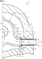
- the FIG. 1 shows a section through the inflow of a double-walled turbomachine z. B. steam turbine.
- the steam turbine 1 comprises a rotor 3 rotatably mounted about a rotation axis 2.
- an inner housing 4 which comprises an inner housing upper part 4a and an inner housing lower part 4b.
- an outer casing 5 which also includes an outer casing upper part 5a and an outer casing lower part 5b.
- a flow channel 6 is formed between the rotor 3 and the inner housing 4.
- a vapor space 7 is formed between the inner housing 4 and the outer housing 5.
- a live steam flows into the flow channel 6.
- the valve 8 comprises a diffuser 9, which is substantially tubular around an axis of symmetry 10.
- a sealing component 12 is arranged, which opens into a groove in a first component 13, which is mechanically fixedly connected to the inner housing 4 or incorporated directly into the inner housing. This compound is formed as vapor-tight as possible.
- the area indicated by the frame 14 is in the FIG. 2 shown in more detail.
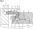
- the FIG. 2 shows the sealing component 12, which is formed as an L-ring substantially rotationally symmetrical about the axis of symmetry 10.
- the sealing component 12 comprises a first leg 15 and a second leg 16 which is at 90 degrees thereto.
- the first leg 15 and the second leg 16 are thus substantially perpendicular to one another.
- the first leg 15 is in this case arranged in a first groove 17 of a first component 3.
- the first component 13 is in this case firmly connected to the inner housing 4 or directly into the Inner housing 4 incorporated.
- the sealing component 12 can thus be moved in the first groove 17 in a direction which leads parallel to the axis of symmetry 10.
- the second leg 16 engages in a second groove 19 in a second component 20.
- the second component 20 includes a diffuser 9, wherein on an inner circumference of the diffuser 9 by means of a thread 21, a third component 22 is arranged such that the second groove 19th between the third component 22 and the diffuser 9 is formed.
- the sealing component is in this case of a sufficiently creep-resistant high-alloy steel, z. B. X13CrMoCoVBNb9-2-1 or Nimonic80A formed.
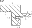
- FIG. 3 is an enlarged view of the first component 13.
- the first component 13 includes a further thread 22, which can be used to be screwed to the inner housing 4.
- the first component comprises a projection 23 which has a surface 24 which is inclined at an angle ⁇ with respect to the axis of symmetry 10.
- the first groove 17 has a first contact surface 25, against which the sealing component 12 rests and on the first contact surface 25, a first coating 26 is arranged.
- the second component 20 comprises a second contact surface 27, against which the sealing component 12 rests, wherein a second coating 28 is arranged on the second contact surface 27.
- the coatings 26 and 28 are superior to the base material in terms of wear and scaling.
- a coating of the contact surfaces of the L-ring is useful, in view of the functionality of the seal assembly.
- the first leg 15 is longer than the second leg 16.
- the FIG. 4 shows an enlarged view of the seal component 12.
- the seal component 12 is seen in cross section an L-ring.
- the first leg 15 has a first contact surface 29, which is formed parallel to the first groove 17.
- the first leg 15 further has a first end face 30, which is formed substantially perpendicular to the first inner contact surface 29.
- the transition 31 from the first inner contact surface 29 to the first end face 30 is formed with a first inner curvature 32.
- the first inner curve 32 may describe a circular arc 33 with a radius R 1 inside .
- the radius R 1, inside is smaller L 1 , where L 1 is the length of the first groove.
- the second leg 16 has a further inner contact surface 34, which is formed parallel to the second groove 19.
- the second leg 16 has a second end face 35, which is formed substantially perpendicular to the second inner contact surface 34.
- the transition 36 from the second inner contact surface 34 to the second end surface 35 has a second inner curvature 37.
- the second inner curvature 37 can be described with a circular arc with a radius R 2, inside .
- the radius R 2, inside is less than / equal to L 2 , where L 2 is the length of the second groove.
- FIG. 5 shows an alternative embodiment of the sealing component 12.
- the difference to the sealing component 12 according to FIG. 4 is that not only on the inside a curvature 39 is formed, but also outside a curvature is arranged on the end faces.
- the first leg 15 has a first outer contact surface 38, which is arranged opposite to the first inner contact surface 29.
- the first outer abutment surface 38 is also formed parallel to the first groove 17, wherein the transition from the curvature 39 from the outer abutment surface 38 to the first end surface 30 has a first outer curvature 40.
- the first outer curvature 40 may be with a circular arc a radius R 1, described outside .
- the radius R 1, outside here is greater L 1 , where L 1 is the length of the second groove.
- the second leg 16 has an outer contact surface 41, which is formed parallel to the second groove 19, wherein the transition 42 from the second outer contact surface 41 to the second end face 35 has a second outer curvature 43.
- the second outer curvature 43 can be described with a circular arc with a radius R 2, outside .
- the radius R 2, outside is smaller L 2 , where L 2 is the length of the second groove
Landscapes
- Engineering & Computer Science (AREA)
- General Engineering & Computer Science (AREA)
- Mechanical Engineering (AREA)
- Gasket Seals (AREA)
Priority Applications (1)
| Application Number | Priority Date | Filing Date | Title |
|---|---|---|---|
| EP18174293.3A EP3572693A1 (fr) | 2018-05-25 | 2018-05-25 | Dispositif d'étanchéité pour une turbomachine |
Applications Claiming Priority (1)
| Application Number | Priority Date | Filing Date | Title |
|---|---|---|---|
| EP18174293.3A EP3572693A1 (fr) | 2018-05-25 | 2018-05-25 | Dispositif d'étanchéité pour une turbomachine |
Publications (1)
| Publication Number | Publication Date |
|---|---|
| EP3572693A1 true EP3572693A1 (fr) | 2019-11-27 |
Family
ID=62386107
Family Applications (1)
| Application Number | Title | Priority Date | Filing Date |
|---|---|---|---|
| EP18174293.3A Withdrawn EP3572693A1 (fr) | 2018-05-25 | 2018-05-25 | Dispositif d'étanchéité pour une turbomachine |
Country Status (1)
| Country | Link |
|---|---|
| EP (1) | EP3572693A1 (fr) |
Citations (5)
| Publication number | Priority date | Publication date | Assignee | Title |
|---|---|---|---|---|
| US4802679A (en) * | 1987-12-31 | 1989-02-07 | Westinghouse Electric Corp. | Bell seal of improved stability for high pressure turbines |
| DE19814442A1 (de) * | 1997-03-31 | 1998-10-01 | Mitsubishi Heavy Ind Ltd | Gasturbinen-Dichtungsvorrichtung |
| EP1515003A1 (fr) * | 2003-09-11 | 2005-03-16 | Siemens Aktiengesellschaft | Turbine à gaz et dispositif d'étanchéité pour une turbine à gaz |
| WO2015176882A1 (fr) * | 2014-05-22 | 2015-11-26 | Siemens Aktiengesellschaft | Liaison amovible à bague angulaire |
| US20180087394A1 (en) * | 2016-09-29 | 2018-03-29 | General Electric Company | Turbine systems with sealing components |
-
2018
- 2018-05-25 EP EP18174293.3A patent/EP3572693A1/fr not_active Withdrawn
Patent Citations (5)
| Publication number | Priority date | Publication date | Assignee | Title |
|---|---|---|---|---|
| US4802679A (en) * | 1987-12-31 | 1989-02-07 | Westinghouse Electric Corp. | Bell seal of improved stability for high pressure turbines |
| DE19814442A1 (de) * | 1997-03-31 | 1998-10-01 | Mitsubishi Heavy Ind Ltd | Gasturbinen-Dichtungsvorrichtung |
| EP1515003A1 (fr) * | 2003-09-11 | 2005-03-16 | Siemens Aktiengesellschaft | Turbine à gaz et dispositif d'étanchéité pour une turbine à gaz |
| WO2015176882A1 (fr) * | 2014-05-22 | 2015-11-26 | Siemens Aktiengesellschaft | Liaison amovible à bague angulaire |
| US20180087394A1 (en) * | 2016-09-29 | 2018-03-29 | General Electric Company | Turbine systems with sealing components |
Similar Documents
| Publication | Publication Date | Title |
|---|---|---|
| DE2931766C2 (de) | Dichtungseinrichtung für die freien Schaufelenden eines Verstell-Leitapparates einer Gasturbine | |
| EP2158381B1 (fr) | Aube directrice pour turbine à gaz | |
| WO2002090724A1 (fr) | Anneau d'enveloppe | |
| DE102008002863A1 (de) | Dichtungsring mit Schwalbenschwanzformabschnitt | |
| EP2396516B1 (fr) | Raccordement de soupape sur une turbomachine à trois coques | |
| EP1378690B1 (fr) | Joint pour l'étanchéité de l'interstice entre deux composants | |
| EP2344730B1 (fr) | Carter intérieur pour une turbomachine | |
| DE102008061800A1 (de) | Segmentierte Dichtlippen für Labyrinthdichtungsringe | |
| DE2459425A1 (de) | Thermische turbomaschine, insbesondere dampfturbine | |
| EP2173974A1 (fr) | Segment de bouclier thermique destiné au stator d'une turbine à gaz | |
| EP1653049B1 (fr) | Couronne d'aubes directrices pour turbines à gaz et procédé pour sa modification | |
| EP2216512A1 (fr) | Turbine à vapeur à trois coques | |
| EP2112334A1 (fr) | Boîtier extérieur pour une turbomachine | |
| EP1960636B1 (fr) | Turbomachine | |
| EP2561256A1 (fr) | Garniture mécanique d'étanchéité dotée d'une contre-bague rotative à serrage défini avec précision | |
| WO2010091928A1 (fr) | Turbine à vapeur à triple coque avec vanne | |
| DE102019204544A1 (de) | Rohrbrennkammersystem und Gasturbinenanlage mit einem solchen Rohrbrennkammersystem | |
| DD141248A3 (de) | Axial verstellbare gleitringdichtung | |
| EP2101042A1 (fr) | Turbine à vapeur dotée de frettes | |
| EP3587738A2 (fr) | Agencement d'étanchéité pour composants de turbomachine | |
| WO2012022550A2 (fr) | Dispositif d'étanchéité | |
| EP2551463A1 (fr) | Raccordement de soupape sur une turbomachine | |
| EP2216514A1 (fr) | Turbine à vapeur à trois coques avec une soupape | |
| DE1030358B (de) | Befestigung eines Duesenkastens im Innengehaeuse einer Doppelgehaeuse-Hochtemperaturturbine | |
| DE102016225604B4 (de) | Dichtungsanordnung, Rotor mit einer solchen Dichtungsanordnung und Gasturbine mit einem solchen Rotor |
Legal Events
| Date | Code | Title | Description |
|---|---|---|---|
| PUAI | Public reference made under article 153(3) epc to a published international application that has entered the european phase |
Free format text: ORIGINAL CODE: 0009012 |
|
| AK | Designated contracting states |
Kind code of ref document: A1 Designated state(s): AL AT BE BG CH CY CZ DE DK EE ES FI FR GB GR HR HU IE IS IT LI LT LU LV MC MK MT NL NO PL PT RO RS SE SI SK SM TR |
|
| AX | Request for extension of the european patent |
Extension state: BA ME |
|
| STAA | Information on the status of an ep patent application or granted ep patent |
Free format text: STATUS: THE APPLICATION IS DEEMED TO BE WITHDRAWN |
|
| 18D | Application deemed to be withdrawn |
Effective date: 20200603 |