EP3572741A1 - Kühlsystem mit ölsteuerungssystem - Google Patents
Kühlsystem mit ölsteuerungssystem Download PDFInfo
- Publication number
- EP3572741A1 EP3572741A1 EP19176127.9A EP19176127A EP3572741A1 EP 3572741 A1 EP3572741 A1 EP 3572741A1 EP 19176127 A EP19176127 A EP 19176127A EP 3572741 A1 EP3572741 A1 EP 3572741A1
- Authority
- EP
- European Patent Office
- Prior art keywords
- oil
- suction line
- compressors
- refrigerant
- control valve
- Prior art date
- Legal status (The legal status is an assumption and is not a legal conclusion. Google has not performed a legal analysis and makes no representation as to the accuracy of the status listed.)
- Granted
Links
Images

Classifications
-
- F—MECHANICAL ENGINEERING; LIGHTING; HEATING; WEAPONS; BLASTING
- F25—REFRIGERATION OR COOLING; COMBINED HEATING AND REFRIGERATION SYSTEMS; HEAT PUMP SYSTEMS; MANUFACTURE OR STORAGE OF ICE; LIQUEFACTION SOLIDIFICATION OF GASES
- F25B—REFRIGERATION MACHINES, PLANTS OR SYSTEMS; COMBINED HEATING AND REFRIGERATION SYSTEMS; HEAT PUMP SYSTEMS
- F25B9/00—Compression machines, plants or systems, in which the refrigerant is air or other gas of low boiling point
- F25B9/002—Compression machines, plants or systems, in which the refrigerant is air or other gas of low boiling point characterised by the refrigerant
- F25B9/008—Compression machines, plants or systems, in which the refrigerant is air or other gas of low boiling point characterised by the refrigerant the refrigerant being carbon dioxide
-
- C—CHEMISTRY; METALLURGY
- C09—DYES; PAINTS; POLISHES; NATURAL RESINS; ADHESIVES; COMPOSITIONS NOT OTHERWISE PROVIDED FOR; APPLICATIONS OF MATERIALS NOT OTHERWISE PROVIDED FOR
- C09K—MATERIALS FOR MISCELLANEOUS APPLICATIONS, NOT PROVIDED FOR ELSEWHERE
- C09K5/00—Heat-transfer, heat-exchange or heat-storage materials, e.g. refrigerants; Materials for the production of heat or cold by chemical reactions other than by combustion
- C09K5/02—Materials undergoing a change of physical state when used
- C09K5/04—Materials undergoing a change of physical state when used the change of state being from liquid to vapour or vice versa
- C09K5/041—Materials undergoing a change of physical state when used the change of state being from liquid to vapour or vice versa for compression-type refrigeration systems
-
- F—MECHANICAL ENGINEERING; LIGHTING; HEATING; WEAPONS; BLASTING
- F25—REFRIGERATION OR COOLING; COMBINED HEATING AND REFRIGERATION SYSTEMS; HEAT PUMP SYSTEMS; MANUFACTURE OR STORAGE OF ICE; LIQUEFACTION SOLIDIFICATION OF GASES
- F25B—REFRIGERATION MACHINES, PLANTS OR SYSTEMS; COMBINED HEATING AND REFRIGERATION SYSTEMS; HEAT PUMP SYSTEMS
- F25B1/00—Compression machines, plants or systems with non-reversible cycle
- F25B1/10—Compression machines, plants or systems with non-reversible cycle with multi-stage compression
-
- F—MECHANICAL ENGINEERING; LIGHTING; HEATING; WEAPONS; BLASTING
- F25—REFRIGERATION OR COOLING; COMBINED HEATING AND REFRIGERATION SYSTEMS; HEAT PUMP SYSTEMS; MANUFACTURE OR STORAGE OF ICE; LIQUEFACTION SOLIDIFICATION OF GASES
- F25B—REFRIGERATION MACHINES, PLANTS OR SYSTEMS; COMBINED HEATING AND REFRIGERATION SYSTEMS; HEAT PUMP SYSTEMS
- F25B31/00—Compressor arrangements
- F25B31/002—Lubrication
- F25B31/004—Lubrication oil recirculating arrangements
-
- F—MECHANICAL ENGINEERING; LIGHTING; HEATING; WEAPONS; BLASTING
- F25—REFRIGERATION OR COOLING; COMBINED HEATING AND REFRIGERATION SYSTEMS; HEAT PUMP SYSTEMS; MANUFACTURE OR STORAGE OF ICE; LIQUEFACTION SOLIDIFICATION OF GASES
- F25B—REFRIGERATION MACHINES, PLANTS OR SYSTEMS; COMBINED HEATING AND REFRIGERATION SYSTEMS; HEAT PUMP SYSTEMS
- F25B43/00—Arrangements for separating or purifying gases or liquids; Arrangements for vaporising the residuum of liquid refrigerant, e.g. by heat
- F25B43/02—Arrangements for separating or purifying gases or liquids; Arrangements for vaporising the residuum of liquid refrigerant, e.g. by heat for separating lubricants from the refrigerant
-
- F—MECHANICAL ENGINEERING; LIGHTING; HEATING; WEAPONS; BLASTING
- F25—REFRIGERATION OR COOLING; COMBINED HEATING AND REFRIGERATION SYSTEMS; HEAT PUMP SYSTEMS; MANUFACTURE OR STORAGE OF ICE; LIQUEFACTION SOLIDIFICATION OF GASES
- F25B—REFRIGERATION MACHINES, PLANTS OR SYSTEMS; COMBINED HEATING AND REFRIGERATION SYSTEMS; HEAT PUMP SYSTEMS
- F25B49/00—Arrangement or mounting of control or safety devices
- F25B49/02—Arrangement or mounting of control or safety devices for compression type machines, plants or systems
-
- C—CHEMISTRY; METALLURGY
- C09—DYES; PAINTS; POLISHES; NATURAL RESINS; ADHESIVES; COMPOSITIONS NOT OTHERWISE PROVIDED FOR; APPLICATIONS OF MATERIALS NOT OTHERWISE PROVIDED FOR
- C09K—MATERIALS FOR MISCELLANEOUS APPLICATIONS, NOT PROVIDED FOR ELSEWHERE
- C09K2205/00—Aspects relating to compounds used in compression type refrigeration systems
- C09K2205/10—Components
- C09K2205/106—Carbon dioxide
-
- F—MECHANICAL ENGINEERING; LIGHTING; HEATING; WEAPONS; BLASTING
- F25—REFRIGERATION OR COOLING; COMBINED HEATING AND REFRIGERATION SYSTEMS; HEAT PUMP SYSTEMS; MANUFACTURE OR STORAGE OF ICE; LIQUEFACTION SOLIDIFICATION OF GASES
- F25B—REFRIGERATION MACHINES, PLANTS OR SYSTEMS; COMBINED HEATING AND REFRIGERATION SYSTEMS; HEAT PUMP SYSTEMS
- F25B2309/00—Gas cycle refrigeration machines
- F25B2309/06—Compression machines, plants or systems characterised by the refrigerant being carbon dioxide
-
- F—MECHANICAL ENGINEERING; LIGHTING; HEATING; WEAPONS; BLASTING
- F25—REFRIGERATION OR COOLING; COMBINED HEATING AND REFRIGERATION SYSTEMS; HEAT PUMP SYSTEMS; MANUFACTURE OR STORAGE OF ICE; LIQUEFACTION SOLIDIFICATION OF GASES
- F25B—REFRIGERATION MACHINES, PLANTS OR SYSTEMS; COMBINED HEATING AND REFRIGERATION SYSTEMS; HEAT PUMP SYSTEMS
- F25B2400/00—Component parts or details not otherwise provided for in this subclass
- F25B2400/07—Details of compressors or related parts
- F25B2400/075—Details of compressors or related parts with parallel compressors
-
- F—MECHANICAL ENGINEERING; LIGHTING; HEATING; WEAPONS; BLASTING
- F25—REFRIGERATION OR COOLING; COMBINED HEATING AND REFRIGERATION SYSTEMS; HEAT PUMP SYSTEMS; MANUFACTURE OR STORAGE OF ICE; LIQUEFACTION SOLIDIFICATION OF GASES
- F25B—REFRIGERATION MACHINES, PLANTS OR SYSTEMS; COMBINED HEATING AND REFRIGERATION SYSTEMS; HEAT PUMP SYSTEMS
- F25B2400/00—Component parts or details not otherwise provided for in this subclass
- F25B2400/23—Separators
-
- F—MECHANICAL ENGINEERING; LIGHTING; HEATING; WEAPONS; BLASTING
- F25—REFRIGERATION OR COOLING; COMBINED HEATING AND REFRIGERATION SYSTEMS; HEAT PUMP SYSTEMS; MANUFACTURE OR STORAGE OF ICE; LIQUEFACTION SOLIDIFICATION OF GASES
- F25B—REFRIGERATION MACHINES, PLANTS OR SYSTEMS; COMBINED HEATING AND REFRIGERATION SYSTEMS; HEAT PUMP SYSTEMS
- F25B2600/00—Control issues
- F25B2600/25—Control of valves
- F25B2600/2515—Flow valves
-
- F—MECHANICAL ENGINEERING; LIGHTING; HEATING; WEAPONS; BLASTING
- F25—REFRIGERATION OR COOLING; COMBINED HEATING AND REFRIGERATION SYSTEMS; HEAT PUMP SYSTEMS; MANUFACTURE OR STORAGE OF ICE; LIQUEFACTION SOLIDIFICATION OF GASES
- F25B—REFRIGERATION MACHINES, PLANTS OR SYSTEMS; COMBINED HEATING AND REFRIGERATION SYSTEMS; HEAT PUMP SYSTEMS
- F25B2700/00—Sensing or detecting of parameters; Sensors therefor
- F25B2700/03—Oil level
Definitions
- the present disclosure relates generally to a refrigeration system and more particularly to a refrigeration system that uses carbon dioxide (i.e., CO 2 ) as a refrigerant.
- CO 2 carbon dioxide
- the present disclosure relates more particularly still to a CO 2 refrigeration system with an oil control system.
- Refrigeration systems are often used to provide cooling to temperature controlled display devices (e.g. cases, merchandisers, etc.) in supermarkets and other similar facilities.
- Vapor compression refrigeration systems are a type of refrigeration system which provides such cooling by circulating a fluid refrigerant (e.g., a liquid and/or vapor) through a thermodynamic vapor compression cycle.
- the refrigerant In a vapor compression cycle, the refrigerant is typically compressed to a high temperature high pressure state (e.g., by a compressor of the refrigeration system), cooled/condensed to a lower temperature state (e.g., in a gas cooler or condenser which absorbs heat from the refrigerant), expanded to a lower pressure (e.g., through an expansion valve), and evaporated to provide cooling by absorbing heat into the refrigerant.
- CO 2 refrigeration systems are a type of vapor compression refrigeration system that use CO 2 as a refrigerant.
- Some CO 2 refrigeration systems include an oil management system which provides oil to one or more compressors of the refrigeration system.
- Oil management systems are typically either active or passive. Active oil control systems use an oil separator to remove oil from the refrigerant and then provide the oil directly to each compressor (e.g., via an oil line connecting the oil separator to each compressor). Passive oil control systems do not include an oil separator and allow the oil to remain mixed with the refrigerant throughout the refrigeration cycle.
- CO 2 refrigeration system that provides cooling for a refrigeration load using carbon dioxide (CO 2 ) as a refrigerant.
- the CO 2 refrigeration system includes a plurality of compressors configured to circulate the CO 2 refrigerant, a suction line configured to deliver the CO 2 refrigerant to the compressors, an oil separator configured to separate oil from the CO 2 refrigerant, and an oil return line configured to deliver the oil from the oil separator to the suction line.
- the oil mixes with the CO 2 refrigerant in the suction line before reaching the compressors.
- the CO 2 refrigeration system includes a plurality of oil equalization lines and a plurality of oil equalization valves.
- Each of the oil equalization lines may connect one of the compressors to the oil return line.
- Each of the oil equalization valves may be located along one of the oil equalization lines and configured to control a flow of oil through the oil equalization lines.
- the CO 2 refrigeration system includes a controller configured to periodically open and close the plurality of oil equalization valves. Opening the oil equalization valves may cause any excess oil within the compressors to flow into the oil equalization lines and equalizes an amount of oil within each of the compressors.
- the CO 2 refrigeration system includes an oil control valve located along the oil return line and configured to control a flow of oil from the oil separator to the suction line.
- the CO 2 refrigeration system includes an oil sensor configured to measure an amount of oil within the suction line.
- the CO 2 refrigeration system includes a controller configured to open and close the oil control valve based on the measured amount of oil within the suction line.
- the oil may be permitted to flow from the oil separator to the suction line when the oil control valve is open and may be prevented from flowing from the oil separator to the suction line when the oil control valve is closed.
- the controller is configured to open the oil control valve in response to a determination that the measured amount of oil within the suction line is less than an oil threshold and keep the oil control valve closed in response to a determination that the measured amount of the oil within the suction line is greater than or equal to the oil threshold.
- Another implementation of the present disclosure is a method for operating a CO 2 refrigeration system that provides cooling for a refrigeration load using carbon dioxide (CO 2 ) as a refrigerant.
- the method includes operating a plurality of compressors to circulate the CO 2 refrigerant within the CO 2 refrigeration system, delivering the CO 2 refrigerant to the compressors via a suction line coupled to an inlet of the compressors, separating oil from the CO 2 refrigerant at an oil separator coupled to an outlet of the compressors via a discharge line, and delivering the oil from the oil separator to the suction line via an oil return line, wherein the oil mixes with the CO 2 refrigerant in the suction line before reaching the compressors.
- CO 2 carbon dioxide
- the method includes returning excess oil from the plurality of compressors to the oil return line via a plurality of oil equalization lines.
- Each oil equalization line may connect one of the compressors to the oil return line.
- the method may include operating a plurality of oil equalization valves to control a flow of the excess oil through the oil equalization lines.
- Each oil equalization valve may be located along one of the oil equalization lines.
- the method includes periodically opening and closing the plurality of oil equalization valves. Opening the oil equalization valves may cause any excess oil within the compressors to flow into the oil equalization lines and may equalize an amount of oil within each of the compressors.
- the method includes operating an oil control valve located along the oil return line to control a flow of oil from the oil separator to the suction line.
- the method includes measuring an amount of oil within the suction line via an oil sensor coupled to the suction line.
- operating the oil control valve includes opening and closing the oil control valve based on the measured amount of oil within the suction line.
- the oil may be permitted to flow from the oil separator to the suction line when the oil control valve is open and may be prevented from flowing from the oil separator to the suction line when the oil control valve is closed.
- operating the oil control valve includes opening the oil control valve in response to a determination that the measured amount of oil within the suction line is less than an oil threshold and keeping the oil control valve closed in response to a determination that the measured amount of the oil within the suction line is greater than or equal to the oil threshold.
- the controller includes one or more processors and one or more non-transitory computer-readable media storing instructions. When executed by the one or more processors, cause the one or more processors to perform operations including operating a plurality of compressors to circulate the CO 2 refrigerant within the CO 2 refrigeration system and obtaining a measurement of an amount of oil within a suction line coupled to an inlet of the compressors.
- the suction line contains a mixture of oil and the CO 2 refrigerant.
- the operations include comparing the amount of oil within the suction line to an oil threshold and operating an oil control valve to control a flow of oil from an oil separator to the compressor suction line.
- the oil from the oil separator mixes with the CO 2 refrigerant in the compressor suction line before reaching the compressors.
- operating the oil control valve includes opening the oil control valve in response to a determination that the amount of oil within the suction line is less than the oil threshold and keeping the oil control valve closed in response to a determination that the amount of the oil within the suction line is greater than or equal to the oil threshold.
- the operations include obtaining a second measurement of the amount of oil within the suction line after opening the oil control valve to release oil from the oil separator into the suction line and deactivating one or more components of the CO 2 refrigeration system in response to the second measurement of the amount of oil within the suction line being less than the oil threshold.
- the operations include opening a plurality of oil equalization valves connecting the plurality of compressors to an oil return line to equalize oil within each of the compressors and closing the plurality of oil equalization valves after a predetermined amount of time has elapsed.
- opening the plurality of oil equalization valves causes any excess oil from the plurality of compressors to return to the oil return line via a plurality of oil equalization lines.
- Each oil equalization line may connect one of the compressors to the oil return line.
- the oil return line receives both the flow of oil from the oil separator and a flow of oil from the oil equalization lines and delivers oil to the suction line.
- the CO 2 refrigeration system may be a vapor compression refrigeration system which uses primarily carbon dioxide (i.e., CO 2 ) as a refrigerant.
- CO 2 carbon dioxide
- the CO 2 refrigeration system is used to provide cooling for temperature controlled display devices in a supermarket or other similar facility.
- the CO 2 refrigeration system includes an oil control system.
- the CO 2 refrigeration system and/or the oil control system include some or all of the features described in U.S. Provisional Patent Application No. 62/460,984 filed February 20, 2017 , the entire disclosure of which is incorporated by reference herein.
- the oil control system may include an oil separator configured to remove oil from the CO 2 refrigerant.
- the oil control system uses a semi-active or semi-passive oil control technique. Unlike active oil control systems that provide oil directly to individual compressors, the oil control system may provide the oil from the oil separate into a refrigerant suction line that feeds into multiple compressors of the CO 2 refrigeration system. The oil may mix with the CO 2 refrigerant in the suction line before reaching the compressors.
- the oil control system includes several oil equalization lines, each of which connects a compressor of the CO 2 refrigeration system to an oil return line.
- the oil equalization lines may connect to the compressors at connection points defining a target level of oil within each compressor.
- the oil control system may include oil equalization valves located along each oil equalization line. The oil equalization valves can be opened simultaneously to equalize the amount of oil within each compressor. When the oil equalization valves are open, any oil within the compressors above the connection points may flow into the oil equalization lines and into the oil return line, whereas any oil below the connection points may remain within the compressors.
- the oil return line may then deliver any returned oil into the compressor suction line to mix with the refrigerant.
- the oil control system may include an oil sensor configured to measure an amount or level of oil within the compressor suction line. If the measured amount of oil in the suction line is less than an oil threshold after the oil equalization procedure has been performed (e.g., two minutes later), an oil control valve may be opened to release oil from the oil separator into the oil return line, which delivers the oil to the compressor suction line. However, if the measured amount of oil in the suction line is greater than or equal to the oil threshold, the oil control valve may remain closed. If the amount of oil in the suction line does not reach the oil threshold after opening the oil control valve, an alarm may be generated and the CO 2 refrigeration system may be shutdown.
- CO 2 refrigeration system 100 may be a vapor compression refrigeration system which uses primarily carbon dioxide (CO 2 ) as a refrigerant.
- CO 2 refrigeration system 100 and is shown to include a system of pipes, conduits, or other fluid channels (e.g., fluid conduits 1, 3, 5, 7, 9, 13, 17, and 19) for transporting the CO 2 refrigerant between various components of CO 2 refrigeration system 100.
- the components of CO 2 refrigeration system 100 are shown to include a gas cooler/condenser 2, a high pressure valve 4, a receiver 6, expansion valves 11, evaporators 12, and compressors 14.
- Gas cooler/condenser 2 may be a heat exchanger or other similar device for removing heat from the CO 2 refrigerant. Gas cooler/condenser 2 is shown receiving CO 2 vapor from fluid conduit 1. In some embodiments, the CO 2 vapor in fluid conduit 1 may have a pressure within a range from approximately 45 bar to approximately 100 bar (i.e., about 640 psig to about 1420 psig), depending on ambient temperature and other operating conditions. In some embodiments, gas cooler/condenser 2 may partially or fully condense CO 2 vapor into liquid CO 2 (e.g., if system operation is in a subcritical region). The condensation process may result in fully saturated CO 2 liquid or a liquid-vapor mixture (e.g., having a thermodynamic quality between zero and one).
- gas cooler/condenser 2 may cool the CO 2 vapor (e.g., by removing superheat) without condensing the CO 2 vapor into CO 2 liquid (e.g., if system operation is in a supercritical region).
- the cooling/condensation process is an isobaric process. Gas cooler/condenser 2 is shown outputting the cooled and/or condensed CO 2 refrigerant into fluid conduit 3.
- High pressure valve 4 receives the cooled and/or condensed CO 2 refrigerant from fluid conduit 3 and outputs the CO 2 refrigerant to fluid conduit 5.
- High pressure valve 4 may control the pressure of the CO 2 refrigerant in gas cooler/condenser 2 by controlling an amount of CO 2 refrigerant permitted to pass through high pressure valve 4.
- high pressure valve 4 is a high pressure thermal expansion valve (e.g., if the pressure in fluid conduit 3 is greater than the pressure in fluid conduit 5). In such embodiments, high pressure valve 4 may allow the CO 2 refrigerant to expand to a lower pressure state.
- the expansion process may be an isenthalpic and/or adiabatic expansion process, resulting in a flash evaporation of the high pressure CO 2 refrigerant to a lower pressure, lower temperature state.
- the expansion process may produce a liquid/vapor mixture (e.g., having a thermodynamic quality between zero and one).
- the CO 2 refrigerant expands to a pressure of approximately 38 bar (e.g., about 540 psig), which corresponds to a temperature of approximately 37° F.
- the CO 2 refrigerant then flows from fluid conduit 5 into receiver 6.
- Receiver 6 collects the CO 2 refrigerant from fluid conduit 5.
- receiver 6 may be a flash tank or other fluid reservoir.
- Receiver 6 includes a CO 2 liquid portion 16 and a CO 2 vapor portion 15 and may contain a partially saturated mixture of CO 2 liquid and CO 2 vapor.
- receiver 6 separates the CO 2 liquid from the CO 2 vapor.
- the CO 2 liquid may exit receiver 6 through fluid conduit 9.
- Fluid conduit 9 may be liquid headers leading to expansion valves 11 and evaporators 12.
- the CO 2 vapor may exit receiver 6 through fluid conduit 7.
- Fluid conduit 7 is shown leading the CO 2 vapor to fluid conduit 13.
- Expansion valves 11 may be electronic expansion valves or other similar expansion valves. Expansion valves 11 are shown receiving liquid CO 2 refrigerant from fluid conduit 9 and outputting the CO 2 refrigerant to evaporators 12. Expansion valves 11 may cause the CO 2 refrigerant to undergo a rapid drop in pressure, thereby expanding the CO 2 refrigerant to a lower pressure, lower temperature state. In some embodiments, expansion valves 11 may expand the CO 2 refrigerant to a pressure of approximately 30 bar. The expansion process may be an isenthalpic and/or adiabatic expansion process.
- Evaporators 12 are shown receiving the cooled and expanded CO 2 refrigerant from expansion valves 11.
- evaporators 12 may be associated with display cases/devices (e.g., if CO 2 refrigeration system 100 is implemented in a supermarket setting).
- Evaporators 12 may be configured to facilitate the transfer of heat from the display cases/devices into the CO 2 refrigerant. The added heat may cause the CO 2 refrigerant to evaporate partially or completely.
- the CO 2 refrigerant is fully evaporated in evaporators 12.
- the evaporation process may be an isobaric process.
- Evaporators 12 are shown outputting the CO 2 refrigerant into discharge line 13, leading to a heat exchanger 20.
- Heat exchanger 20 may be positioned within receiver 6 and configured to transfer heat between the CO 2 refrigerant entering heat exchanger 20 from discharge line 13 and the CO 2 refrigerant entering receiver 6 from fluid conduit 5. In some embodiments, heat exchanger 20 precools the CO 2 refrigerant within receiver 6 by transferring heat from the CO 2 refrigerant surrounding heat exchanger 20 into the CO 2 refrigerant within heat exchanger 20. The CO 2 refrigerant exiting heat exchanger 20 may pass into suction line 17. In other embodiments, heat exchanger 20 can be omitted and discharge line 13 may connect directly to suction line 17. Suction line 17 may provide the CO 2 refrigerant to compressors 14.
- Compressors 14 may compress the CO 2 refrigerant into a superheated vapor having a pressure within a range of approximately 45 bar to approximately 100 bar.
- the output pressure from compressors 14 may vary depending on ambient temperature and other operating conditions.
- compressors 14 operate in a transcritical mode.
- the CO 2 discharge gas exits compressors 14 and flows into discharge line 19.
- Discharge line 19 is shown providing the CO 2 refrigerant to an oil separator 31, which separates oil from the CO 2 refrigerant.
- the CO 2 refrigerant may exit oil separator 31 and flow through fluid conduit 1 into gas cooler/condenser 2.
- the oil separated from the CO 2 refrigerant may flow into an oil return line 33.
- CO 2 refrigeration system 100 is shown to include a gas bypass valve 8.
- Gas bypass valve 8 may receive the CO 2 vapor from receiver 6 (via fluid conduit 7) and output the CO 2 refrigerant into discharge line 13.
- the CO 2 vapor that is bypassed through gas bypass valve 8 is mixed with the CO 2 refrigerant gas exiting evaporators 12 (e.g., via discharge line 13).
- the combined CO 2 refrigerant gas may be provided to the suction side of compressors 14.
- gas bypass valve 8 may output the CO 2 refrigerant into suction line 17.
- Compressors 14 may compress the CO 2 vapor passing through gas bypass valve 8 from a low pressure state (e.g., approximately 30 bar or lower) to a high pressure state (e.g., 45-100 bar).
- Gas bypass valve 8 may be operated to regulate or control the pressure within receiver 6 (e.g., by adjusting an amount of CO 2 refrigerant permitted to pass through gas bypass valve 8).
- gas bypass valve 8 may be adjusted (e.g., variably opened or closed) to adjust the mass flow rate, volume flow rate, or other flow rates of the CO 2 refrigerant through gas bypass valve 8.
- Gas bypass valve 8 may be opened and closed (e.g., manually, automatically, by a controller 50, etc.) as needed to regulate the pressure within receiver 6.
- gas bypass valve 8 includes a sensor for measuring a flow rate (e.g., mass flow, volume flow, etc.) of the CO 2 refrigerant through gas bypass valve 8.
- gas bypass valve 8 includes an indicator (e.g., a gauge, a dial, etc.) from which the position of gas bypass valve 8 may be determined. This position may be used to determine the flow rate of CO 2 refrigerant through gas bypass valve 8, as such quantities may be proportional or otherwise related.
- gas bypass valve 8 may be a thermal expansion valve (e.g., if the pressure on the downstream side of gas bypass valve 8 is lower than the pressure in fluid conduit 7).
- the pressure within receiver 6 is regulated by gas bypass valve 8 to a pressure of approximately 38 bar, which corresponds to about 37 °F.
- this pressure/temperature state may facilitate the use of copper tubing/piping for the downstream CO 2 lines of the system. Additionally, this pressure/temperature state may allow such copper tubing to operate in a substantially frost-free manner.
- CO 2 refrigeration system 100 is shown to include an oil control system 30.
- Oil control system 30 can be configured to monitor and control the oil delivered to compressors 14.
- the oil control performed by oil control system 30 is semi-active or semi-passive.
- Active oil control systems typically use an oil separator to remove oil from the refrigerant and then provide the oil directly to each compressor (e.g., via an oil line connecting the oil separator to each compressor).
- Passive oil control systems typically do not include an oil separator and allow the oil to remain mixed with the refrigerant throughout the refrigeration cycle.
- the semi-active or semi-passive oil control performed by oil control system 30 may remove oil from the CO 2 refrigerant, but does not provide the oil directly to each compressor 14. Rather, the oil is returned to suction line 17 via oil return line 33 and mixed with the CO 2 refrigerant before the CO 2 refrigerant is provided to compressors 14.
- Oil control system 30 is shown to include an oil separator 31.
- Oil separator 31 may be configured to separate oil from the compressed CO 2 refrigerant.
- oil separator 31 is positioned downstream of compressors 14 (as shown in FIG. 1 ) such that oil separator 31 receives the compressed CO 2 refrigerant from discharge line 19.
- Oil separator 31 may remove oil from the compressed CO 2 refrigerant and may deliver the compressed CO 2 refrigerant into fluid conduit 1.
- the oil separated from the CO 2 refrigerant is collected in oil separator 31.
- the oil can be stored in an internal reservoir within oil separator 31. In other embodiments, the oil can be stored in an external reservoir separate from oil separator 31.
- Oil separated from the CO 2 refrigerant by oil separator 31 may exit the internal or external oil reservoir via oil return line 33.
- Oil return line 33 connects oil separator 31 and/or the oil reservoir to suction line 17 where the oil mixes with the CO 2 refrigerant.
- the refrigerant/oil mixture then feeds into compressors 14.
- An oil control valve 39 (e.g., a solenoid valve) may be positioned along oil return line 33 and configured to control the flow of oil through oil return line 33.
- Oil control valve 39 can be operated by controller 50 (described in greater detail below) to control the release of oil from oil separator 31 into suction line 17.
- oil control system 30 Unlike active oil control systems that provide oil directly to individual compressors, oil control system 30 provides the oil into a refrigerant suction line 17 that feeds into multiple compressors 14 in parallel. The oil may mix with the CO 2 refrigerant in suction line 17 before reaching compressors 14. The flow of oil back to compressors 14 may be balanced such that each compressor 14 receives sufficient oil.
- oil control system 30 is shown to include several oil equalization lines 36 and oil equalization valves 37.
- Each oil equalization line 36 connects one of compressors 14 to oil return line 33 and is configured to deliver oil and/or CO 2 refrigerant from the corresponding compressor 14 into oil return line 33.
- oil equalization lines 36 are connected to the crank casings of compressors 14.
- Oil equalization lines 36 may connect to compressors 14 at connection points corresponding to the desired oil level (e.g., the maximum allowable oil level or maximum desirable oil level) within each of compressors 14.
- any oil within compressors 14 above the desired oil level can flow into oil equalization lines 36 when valves 37 are opened, whereas any oil within compressors 14 below the desired oil level (i.e., below the connection point) may remain within compressors 14 when valves 37 are opened.
- Each oil equalization valve 37 may be positioned along one of oil equalization lines 36 and can be operated (e.g., by controller 50) to control the flow of oil through the corresponding oil equalization line 36.
- oil equalization valves 37 are periodically opened and closed by controller 50 to equalize the amount of oil within each of compressors 14. For example, when compressors 14 are running, all oil equalization valves 37 may be opened simultaneously for a predetermined amount of time (e.g., ten seconds) and subsequently closed after the predetermined amount of time has elapsed. If the oil level within any of compressors 14 is above the connection point, any oil above the connection point may flow into oil equalization lines 36, through oil equalization valves 37, and into oil return line 33 while valves 37 are open.
- a predetermined amount of time e.g., ten seconds
- any such compressors 14 may return only CO 2 refrigerant gas through oil equalization lines 36 when valves 37 are opened. In this way, the level of oil within each of compressors 14 is equalized.
- the process of opening and closing oil equalization valves 37 to equalize the amount of oil within compressors 14 is referred to herein as an oil equitation procedure.
- oil control system 30 includes an oil sensor 35.
- Oil sensor 35 may be located along suction line 17 and configured to measure the amount of oil within the refrigerant/oil mixture in suction line 17.
- Oil sensor 35 can be any of a variety of sensor types (e.g., optical, capacitive, dielectrical, resonance frequency, floating bulb, etc.) configured to sense the amount of oil in the refrigerant/oil mixture in suction line 17.
- oil sensor 35 uses a frequency sweep technique to sense oil, either as a mist or as a liquid oil level, within suction line 17.
- oil sensor 35 may be a Baumer frequency sweep sensor configured to sense the amount of oil in the oil/refrigerant mixture within suction line 17.
- oil sensor 35 is used to sense the amount of oil within suction line 17 shortly after the oil equalization procedure is performed. For example, oil sensor 35 may sense the amount of oil within suction line 17 approximately two minutes (or any other amount of time) after the oil equalization procedure is performed. Controller 50 may compare the oil measurement from oil sensor 35 with a threshold oil value. If the oil measurement is greater than or equal to the threshold oil value (i.e., the amount of oil within suction line 17 is above the threshold), controller 50 may cause oil control valve 39 to remain closed.
- controller 50 may cause oil control valve 39 to open for a predetermined amount of time (e.g., five seconds) to allow oil from oil separator 31 to flow into oil return line 33.
- oil control valve 39 can be held open until the oil measurement obtained by oil sensor 35 reaches the threshold oil value rather than closing oil control valve after the predetermined amount of time has elapsed.
- controller 50 may generate an alarm indicating that insufficient oil is present within oil control system 30. Upon generating the alarm, controller 50 may automatically stop the operation of CO 2 refrigeration system 100 (e.g., by stopping compressors 14) to prevent any damage that could be caused by insufficient oil.
- Controller 50 may receive signals from one or more measurement devices (e.g., pressure sensors, temperature sensors, flow sensors, etc.) located within CO 2 refrigeration system 100. For example, controller 50 is shown receiving an oil measurement from oil sensor 35. Controller 50 may also receive a compressor state signal from one or more of compressors 14. The compressor state signals may indicate which of compressors 14 are running and which of compressors 14 are not running. Controller 50 may use the oil measurement and the compressor states to determine appropriate control actions for control devices of CO 2 refrigeration system 100 (e.g., compressors 14, valves 4, 8, 11, 37, and 39, flow diverters, power supplies, etc.).
- control devices of CO 2 refrigeration system 100 e.g., compressors 14, valves 4, 8, 11, 37, and 39, flow diverters, power supplies, etc.
- controller 50 is configured to operate gas bypass valve 8 to maintain the CO 2 pressure within receiver 6 at a desired setpoint or within a desired range.
- controller 50 operates gas bypass valve 8 based on the temperature of the CO 2 refrigerant at the outlet of gas cooler/condenser 2.
- controller 50 operates gas bypass valve 8 based a flow rate (e.g., mass flow, volume flow, etc.) of CO 2 refrigerant through gas bypass valve 8.
- Controller 50 may use a valve position of gas bypass valve 8 as a proxy for CO 2 refrigerant flow rate.
- controller 50 operates high pressure valve 4 and expansion valves 11 to regulate the flow of refrigerant in system 100.
- controller 50 operates valves 37 and 39 to regulate the flow of oil in oil control system 30.
- Controller 50 may include feedback control functionality for adaptively operating the various components of CO 2 refrigeration system 100.
- controller 50 may receive a setpoint (e.g., a temperature setpoint, a pressure setpoint, a flow rate setpoint, a power usage setpoint, etc.) and operate one or more components of system 100 to achieve the setpoint.
- the setpoint may be specified by a user (e.g., via a user input device, a graphical user interface, a local interface, a remote interface, etc.) or automatically determined by controller 50 based on a history of data measurements.
- controller 50 includes some or all of the features of the controller described in P.C.T. Patent Application No. PCT/US2016/044164 filed July 27, 2016 , and/or U.S. Provisional Patent Application No. 62/460,984 filed February 20, 2017 , the entire disclosures of which are incorporated by reference herein.
- Controller 50 may be a proportional-integral (PI) controller, a proportional-integral-derivative (PID) controller, a pattern recognition adaptive controller (PRAC), a model recognition adaptive controller (MRAC), a model predictive controller (MPC), or any other type of controller employing any type of control functionality.
- controller 50 is a local controller for CO 2 refrigeration system 100.
- controller 50 is a supervisory controller for a plurality of controlled subsystems (e.g., a refrigeration system, an AC system, a lighting system, a security system, etc.).
- controller 50 may be a controller for a comprehensive building management system incorporating CO 2 refrigeration system 100. Controller 50 may be implemented locally, remotely, or as part of a cloud-hosted suite of building management applications.
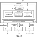
- controller 50 is shown to include a communications interface 52 and a processing circuit 60.
- Communications interface 52 can be or include wired or wireless interfaces (e.g., jacks, antennas, transmitters, receivers, transceivers, wire terminals, etc.) for conducting electronic data communications.
- communications interface 52 may be used to conduct communications with gas bypass valve 8, oil sensor 35, compressors 14, valves 11, 37, and 39, high pressure valve 4, various data acquisition devices within CO 2 refrigeration system 100 (e.g., temperature sensors, pressure sensors, flow sensors, etc.) and/or other external devices or data sources.
- Data communications may be conducted via a direct connection (e.g., a wired connection, an ad-hoc wireless connection, etc.) or a network connection (e.g., an Internet connection, a LAN, WAN, or WLAN connection, etc.).
- communications interface 52 can include an Ethernet card and port for sending and receiving data via an Ethernet-based communications link or network.
- communications interface 52 can include a Wi-Fi transceiver or a cellular or mobile phone transceiver for communicating via a wireless communications network.
- Processing circuit 60 is shown to include a processor 62 and memory 70.
- Processor 62 can be implemented as a general purpose processor, an application specific integrated circuit (ASIC), one or more field programmable gate arrays (FPGAs), a group of processing components, a microcontroller, or other suitable electronic processing components.
- Memory 70 e.g., memory device, memory unit, storage device, etc.
- Memory 70 may be one or more devices (e.g., RAM, ROM, solid state memory, hard disk storage, etc.) for storing data and/or computer code for completing or facilitating the various processes, layers and modules described in the present application.
- Memory 70 may be or include volatile memory or non-volatile memory.
- Memory 70 may include database components, object code components, script components, or any other type of information structure for supporting the various activities and information structures described in the present application. According to an exemplary embodiment, memory 70 is communicably connected to processor 62 via processing circuit 60 and includes computer code for executing (e.g., by processing circuit 60 and/or processor 62) one or more processes or control features described herein.
- controller 50 is shown to include an oil detector 72 and a compressor state detector 74.
- Oil detector 72 can be configured to detect the level or amount of oil within suction line 17 based on the oil measurement from oil sensor 35. For example, oil detector 72 can determine whether the amount or level of oil within the oil/refrigerant mixture in suction line 17 exceeds a threshold oil level.
- Compressor state detector 74 can be configured to detect the state of each of compressors 14. For example, compressor state detector 74 can determine whether each of compressors 14 is currently running or not running.
- Controller 50 is shown to include a valve controller 76.
- Valve controller 76 may receive input from oil detector 72 indicating the current oil amount or level within suction line 17.
- Valve controller 76 may also receive input from compressor state detector 74 indicating the current state of each of compressors 14.
- Valve controller 76 can generate control signals for one or more of valves 4, 8, 11, 37, and 39 based on the current oil amount/level and/or the current state of compressors 14.
- valve controller 76 causes oil equalization valves 37 to open and close periodically.
- valve controller 76 can cause oil equalization valves 37 to open for a predetermined amount of time (e.g., ten seconds) at a periodic interval (e.g., every thirty minutes).
- the predetermined amount of time and the periodic interval are adjustable and can be set to any amount of time, as may be desirable in various implementations.
- valve controller 76 causes all of oil equalization valves 37 to open simultaneously. After the predetermined amount of time has expired, valve controller 76 may cause oil equalization valves 37 to close simultaneously.
- opening and closing oil equalization valves 37 may equalize the amount of oil within each of compressors 14.
- valve controller 76 uses the oil measurement from oil sensor 35 to generate control signals for oil control valve 39. For example, valve controller 76 can compare the oil measurement from oil sensor 35 to an oil threshold. Valve controller 76 may open oil control valve 39 in response to a determination that the amount of oil within suction line 17 is less than the oil threshold. Opening oil control valve 39 may cause oil to be dispensed from oil separator 31 and flow into suction line 17 via oil return line 33. However, if the amount of oil within suction line 17 is greater than or equal to the oil threshold, valve controller 76 may cause oil control valve 39 to remain closed.
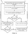
- Process 80 can be performed by one or more components of CO 2 refrigeration system 100. In some embodiments, process 80 is performed by controller 50, as described with reference to FIGS. 1-2 .
- Process 80 is shown to include opening oil equalization valves 37 connecting compressors 14 to compressor suction line 17 to equalize oil within each compressor 14 (step 81) and closing oil equalization valves 37 after a predetermined amount of time has elapsed (step 82).
- Step 81 may include opening oil equalization valves 37 simultaneously to allow oil from within each compressor 14 to flow through oil equalization lines 36 and into oil return line 33.
- oil equalization valves 37 are open, any excess oil within compressors 14 may flow into oil equalization lines 36 and into oil return line 33.
- Excess oil may include any oil within compressors 14 above the point at which oil equalization lines 37 connect to compressors 14. Any oil within compressors 14 below the connection point may remain in compressors 14.
- steps 81 and 82 are performed periodically (e.g., every ten minutes, every thirty minutes, etc.).
- the predetermined amount of time for which valves 37 are held open may be configurable and can be set to any desired value (e.g., ten seconds, five seconds, thirty seconds, etc.)
- Process 80 is shown to include measuring an amount of oil within a compressor suction line 17 containing a mixture of oil and refrigerant (step 83).
- step 83 is performed by oil sensor 35.
- Oil sensor 35 can sense the amount of oil within suction line 17 and can provide an oil measurement to controller 50.
- step 83 is performed a predetermined amount of time (e.g., two minutes) after oil equalization valves 37 are opened and closed.
- process 80 may include waiting for two minutes (or any other amount of time) after step 82 is performed before advancing to step 83. This may allow the oil within suction line 17 to equilibrate before oil sensor 35 is used to measure the amount of oil.
- Process 80 is shown to include comparing the measured amount of oil to an oil threshold (step 84). If the measured amount of oil within suction line 17 is not less than the oil threshold (i.e., the measured amount of oil is greater than or equal to the oil threshold), controller 50 may cause oil control valve 39 to remain closed (step 85) and process 80 may return to step 81 at the next equalization time (e.g., after thirty minutes). However, if the measured amount of oil within suction line 17 is less than the oil threshold, controller 50 may cause oil control valve 39 to open to release oil from oil separator 31 and into suction line 17 via oil return line 33 (step 86).
- oil control valve 39 is held open for a predetermined amount of time (e.g., five seconds, ten seconds, etc.) and then closed. In other embodiments, oil control valve 39 is held open until the measured amount of oil reaches the oil threshold.
- a predetermined amount of time e.g., five seconds, ten seconds, etc.
- step 87 is performed a predetermined amount of time (e.g., two minutes) after oil control valve 39 is opened.
- process 80 may include waiting for two minutes (or any other amount of time) after step 86 is performed before advancing to step 87. This may allow the oil within suction line 17 to equilibrate before oil sensor 35 is used to measure the amount of oil.
- controller 50 may determine that there is sufficient oil in system 100 and process 80 may return to step 81. However, if the measured amount of oil within suction line 17 is less than the oil threshold, controller 50 may generate an alarm indicating insufficient oil and may shutdown system 100 (step 88). Process 80 may be repeated again at the next equalization time (e.g., thirty minutes later or at any other periodic interval).
- Coupled means the joining of two members directly or indirectly to one another. Such joining may be stationary (e.g., permanent) or moveable (e.g., removable or releasable). Such joining may be achieved with the two members or the two members and any additional intermediate members being integrally formed as a single unitary body with one another or with the two members or the two members and any additional intermediate members being attached to one another.
- the present disclosure contemplates methods, systems and program products on memory or other machine-readable media for accomplishing various operations.
- the embodiments of the present disclosure may be implemented using existing computer processors, or by a special purpose computer processor for an appropriate system, incorporated for this or another purpose, or by a hardwired system.
- Embodiments within the scope of the present disclosure include program products or memory including machine-readable media for carrying or having machine-executable instructions or data structures stored thereon.
- Such machine-readable media can be any available media that can be accessed by a general purpose or special purpose computer or other machine with a processor.
- machine-readable media can comprise RAM, ROM, EPROM, EEPROM, CD-ROM or other optical disk storage, magnetic disk storage or other magnetic storage devices, or any other medium which can be used to carry or store desired program code in the form of machine-executable instructions or data structures and which can be accessed by a general purpose or special purpose computer or other machine with a processor. Combinations of the above are also included within the scope of machine-readable media.
- Machine-executable instructions include, for example, instructions and data which cause a general purpose computer, special purpose computer, or special purpose processing machines to perform a certain function or group of functions.
Landscapes
- Engineering & Computer Science (AREA)
- Physics & Mathematics (AREA)
- Thermal Sciences (AREA)
- General Engineering & Computer Science (AREA)
- Mechanical Engineering (AREA)
- Chemical & Material Sciences (AREA)
- Chemical Kinetics & Catalysis (AREA)
- Power Engineering (AREA)
- Analytical Chemistry (AREA)
- Combustion & Propulsion (AREA)
- Materials Engineering (AREA)
- Organic Chemistry (AREA)
- Lubricants (AREA)
Priority Applications (1)
| Application Number | Priority Date | Filing Date | Title |
|---|---|---|---|
| EP24156936.7A EP4365517A3 (de) | 2018-05-24 | 2019-05-23 | Kühlsystem mit ölsteuerungssystem |
Applications Claiming Priority (1)
| Application Number | Priority Date | Filing Date | Title |
|---|---|---|---|
| US201862675868P | 2018-05-24 | 2018-05-24 |
Related Child Applications (2)
| Application Number | Title | Priority Date | Filing Date |
|---|---|---|---|
| EP24156936.7A Division EP4365517A3 (de) | 2018-05-24 | 2019-05-23 | Kühlsystem mit ölsteuerungssystem |
| EP24156936.7A Division-Into EP4365517A3 (de) | 2018-05-24 | 2019-05-23 | Kühlsystem mit ölsteuerungssystem |
Publications (2)
| Publication Number | Publication Date |
|---|---|
| EP3572741A1 true EP3572741A1 (de) | 2019-11-27 |
| EP3572741B1 EP3572741B1 (de) | 2024-03-27 |
Family
ID=66647083
Family Applications (2)
| Application Number | Title | Priority Date | Filing Date |
|---|---|---|---|
| EP19176127.9A Active EP3572741B1 (de) | 2018-05-24 | 2019-05-23 | Kühlsystem mit ölsteuerungssystem |
| EP24156936.7A Pending EP4365517A3 (de) | 2018-05-24 | 2019-05-23 | Kühlsystem mit ölsteuerungssystem |
Family Applications After (1)
| Application Number | Title | Priority Date | Filing Date |
|---|---|---|---|
| EP24156936.7A Pending EP4365517A3 (de) | 2018-05-24 | 2019-05-23 | Kühlsystem mit ölsteuerungssystem |
Country Status (5)
| Country | Link |
|---|---|
| US (2) | US11796227B2 (de) |
| EP (2) | EP3572741B1 (de) |
| CA (1) | CA3044005A1 (de) |
| ES (1) | ES2988987T3 (de) |
| MX (2) | MX2024001272A (de) |
Cited By (2)
| Publication number | Priority date | Publication date | Assignee | Title |
|---|---|---|---|---|
| CN112113361A (zh) * | 2020-09-09 | 2020-12-22 | 北京航空航天大学 | 一种等温压缩高效制冷装置及其方法 |
| WO2023039445A1 (en) * | 2021-09-07 | 2023-03-16 | Hill Phoenix, Inc. | Oil management in refrigeration systems |
Families Citing this family (4)
| Publication number | Priority date | Publication date | Assignee | Title |
|---|---|---|---|---|
| US11788779B2 (en) | 2020-09-25 | 2023-10-17 | Carrier Corporation | Multi-compressor oil equalization |
| WO2025169218A1 (en) * | 2024-02-05 | 2025-08-14 | Indian Institute Of Science | A method and system for managing compressor oil in a carbon dioxide based cooling system |
| WO2025191565A2 (en) * | 2024-03-13 | 2025-09-18 | Lava Energy Ltd | Temperature control of a heat source or a heat sink |
| US20250362062A1 (en) * | 2024-05-21 | 2025-11-27 | Hill Phoenix, Inc. | Co2 refrigeration system with superheat control |
Citations (4)
| Publication number | Priority date | Publication date | Assignee | Title |
|---|---|---|---|---|
| US4589263A (en) * | 1984-04-12 | 1986-05-20 | Hussmann Corporation | Multiple compressor oil system |
| GB2460726A (en) * | 2008-06-13 | 2009-12-16 | Arctic Circle Ltd | Oil circulation in a refrigeration system |
| US20100199707A1 (en) * | 2009-02-11 | 2010-08-12 | Star Refrigeration Limited | Refrigeration system |
| US20110036110A1 (en) * | 2008-05-02 | 2011-02-17 | Daikin Industries, Ltd. | Refrigeration apparatus |
Family Cites Families (73)
| Publication number | Priority date | Publication date | Assignee | Title |
|---|---|---|---|---|
| US4270363A (en) | 1979-04-16 | 1981-06-02 | Schneider Metal Manufacturing Company | Refrigerating machine including energy conserving heat exchange apparatus |
| US4827789A (en) | 1984-06-26 | 1989-05-09 | Western Gear Corporation | Linear actuator |
| JPS63177684U (de) * | 1987-05-07 | 1988-11-17 | ||
| US5369958A (en) * | 1992-10-15 | 1994-12-06 | Mitsubishi Denki Kabushiki Kaisha | Air conditioner |
| US5425246A (en) | 1994-03-03 | 1995-06-20 | General Electric Company | Refrigerant flow rate control based on evaporator dryness |
| KR100343639B1 (ko) * | 1994-06-29 | 2002-11-23 | 다이킨 고교 가부시키가이샤 | 공기조화장치의균유운전제어장치 |
| US5539382A (en) | 1995-04-21 | 1996-07-23 | Carrier Corporation | System for monitoring the operation of a condenser unit |
| US6418735B1 (en) | 2000-11-15 | 2002-07-16 | Carrier Corporation | High pressure regulation in transcritical vapor compression cycles |
| US6385980B1 (en) | 2000-11-15 | 2002-05-14 | Carrier Corporation | High pressure regulation in economized vapor compression cycles |
| JP2002242833A (ja) | 2001-02-15 | 2002-08-28 | Toshiba Kyaria Kk | 冷凍サイクル装置 |
| US6415611B1 (en) | 2001-02-22 | 2002-07-09 | Praxair Technology, Inc. | Cryogenic refrigeration system using magnetic refrigerator forecooling |
| JP4108957B2 (ja) | 2001-10-19 | 2008-06-25 | 東芝キヤリア株式会社 | 冷凍装置 |
| JP3966044B2 (ja) | 2002-04-02 | 2007-08-29 | 株式会社デンソー | 空調装置 |
| US7065979B2 (en) | 2002-10-30 | 2006-06-27 | Delaware Capital Formation, Inc. | Refrigeration system |
| JP2004257694A (ja) | 2003-02-27 | 2004-09-16 | Denso Corp | 蒸気圧縮式冷凍機 |
| JP2005024210A (ja) | 2003-07-01 | 2005-01-27 | Denso Corp | 蒸気圧縮式冷凍機 |
| JP2005037093A (ja) | 2003-07-18 | 2005-02-10 | Tgk Co Ltd | 冷凍サイクル |
| CN1291196C (zh) | 2004-02-18 | 2006-12-20 | 株式会社电装 | 具有多蒸发器的喷射循环 |
| US20050217278A1 (en) | 2004-03-31 | 2005-10-06 | Mongia Rajiv K | Apparatus to use a magnetic based refrigerator in mobile computing device |
| US7010925B2 (en) | 2004-06-07 | 2006-03-14 | Carrier Corporation | Method of controlling a carbon dioxide heat pump water heating system |
| DK1794510T3 (da) | 2004-08-09 | 2012-05-21 | Carrier Corp | CO2 kølekredsløb med underkøling af det flydende kølemiddel med receiver-flashgassen samt fremgangsmåde til drift af dette |
| WO2006015629A1 (en) | 2004-08-09 | 2006-02-16 | Carrier Corporation | Flashgas removal from a receiver in a refrigeration circuit |
| JP4465686B2 (ja) | 2004-09-30 | 2010-05-19 | 株式会社前川製作所 | アンモニア/co2冷凍システム |
| DK2273214T3 (da) | 2005-02-18 | 2014-01-13 | Carrier Corp | Fremgangsmåde til styring af højtryk i et intermitterende superkritisk driftskølekredsløb |
| AU2005327954A1 (en) | 2005-02-18 | 2006-08-31 | Carrier Corporation | Refrigeration circuit with improved liquid/vapour receiver |
| EP1853856A1 (de) | 2005-02-18 | 2007-11-14 | Carrier Corporation | Co2-kältevorrichtung mit wärmerückgewinnung |
| US8011192B2 (en) | 2005-06-23 | 2011-09-06 | Hill Phoenix, Inc. | Method for defrosting an evaporator in a refrigeration circuit |
| JP4592616B2 (ja) | 2006-02-27 | 2010-12-01 | 三洋電機株式会社 | 冷凍サイクル装置 |
| US20080006044A1 (en) | 2006-07-10 | 2008-01-10 | Ziming Tan | Method for controlling temperature |
| JP2008064439A (ja) | 2006-09-11 | 2008-03-21 | Daikin Ind Ltd | 空気調和装置 |
| KR101492115B1 (ko) | 2006-10-26 | 2015-02-10 | 존슨 컨트롤스 테크놀러지 컴퍼니 | 이코노마이즈드 냉동 시스템 |
| NO327832B1 (no) | 2007-06-29 | 2009-10-05 | Sinvent As | Dampkompresjons-kjolesystem med lukket krets samt fremgangsmate for drift av systemet. |
| EP2212631B1 (de) | 2007-10-10 | 2016-12-07 | Carrier Corporation | Kühlsystem und steuerverfahren dafür |
| DK2220450T4 (da) | 2007-11-09 | 2023-02-20 | Carrier Corp | Transportkølesystem og fremgangsmåde til anvendelse deraf |
| KR101689525B1 (ko) | 2007-12-28 | 2016-12-26 | 존슨 컨트롤스 테크놀러지 컴퍼니 | 증기 압축 시스템 |
| US7913506B2 (en) | 2008-04-22 | 2011-03-29 | Hill Phoenix, Inc. | Free cooling cascade arrangement for refrigeration system |
| US9151521B2 (en) | 2008-04-22 | 2015-10-06 | Hill Phoenix, Inc. | Free cooling cascade arrangement for refrigeration system |
| US8631666B2 (en) | 2008-08-07 | 2014-01-21 | Hill Phoenix, Inc. | Modular CO2 refrigeration system |
| US20110138831A1 (en) * | 2008-08-22 | 2011-06-16 | Panasonic Corporation | Refrigeration cycle apparatus |
| CN102165276B (zh) | 2008-09-29 | 2013-03-27 | 开利公司 | 具有闪蒸罐经济器的蒸气压缩系统及其控制方法 |
| US20120055182A1 (en) | 2008-10-23 | 2012-03-08 | Dube Serge | Co2 refrigeration system |
| JP2010216685A (ja) | 2009-03-13 | 2010-09-30 | Daikin Ind Ltd | ヒートポンプシステム |
| EP2417406B1 (de) | 2009-04-09 | 2019-03-06 | Carrier Corporation | Kühlungsdampf-kompressionssystem mit heissgasumleitung |
| US10088202B2 (en) | 2009-10-23 | 2018-10-02 | Carrier Corporation | Refrigerant vapor compression system operation |
| CN102667372B (zh) | 2009-11-25 | 2015-09-09 | 开利公司 | 用于制冷剂蒸汽压缩系统的低吸入压力保护 |
| WO2011071959A2 (en) | 2009-12-08 | 2011-06-16 | Get Green Energy Corporation | Heat pump |
| EP2596302B1 (de) | 2010-07-23 | 2014-03-19 | Carrier Corporation | Ejektorzyklus |
| CA2724255C (en) | 2010-09-28 | 2011-09-13 | Serge Dube | Co2 refrigeration system for ice-playing surfaces |
| US9541311B2 (en) | 2010-11-17 | 2017-01-10 | Hill Phoenix, Inc. | Cascade refrigeration system with modular ammonia chiller units |
| US9664424B2 (en) | 2010-11-17 | 2017-05-30 | Hill Phoenix, Inc. | Cascade refrigeration system with modular ammonia chiller units |
| US9657977B2 (en) | 2010-11-17 | 2017-05-23 | Hill Phoenix, Inc. | Cascade refrigeration system with modular ammonia chiller units |
| CA2735347C (en) | 2011-03-28 | 2011-10-11 | Serge Dube | Co2 refrigeration system for ice-playing surface |
| DK177329B1 (en) | 2011-06-16 | 2013-01-14 | Advansor As | Refrigeration system |
| CN103649651B (zh) | 2011-07-05 | 2016-01-20 | 丹佛斯公司 | 用于控制亚临界和超临界模式下的蒸汽压缩系统的运行的方法 |
| WO2013030896A1 (ja) | 2011-09-01 | 2013-03-07 | 三菱電機株式会社 | 冷凍サイクル装置 |
| KR20130041640A (ko) | 2011-10-17 | 2013-04-25 | 엘지전자 주식회사 | 공기조화기 및 그 운전 방법 |
| WO2013078088A1 (en) | 2011-11-21 | 2013-05-30 | Hill Phoenix, Inc. | C02 refrigeration system with hot gas defrost |
| US9951962B2 (en) | 2011-12-06 | 2018-04-24 | Mitsubishi Electric Corporation | Heat pump heating and hot-water system |
| CA2766361A1 (en) | 2012-01-30 | 2013-07-30 | Serge Dube | Co2 refrigeration system for ice-playing surface |
| CA2771113A1 (en) | 2012-03-08 | 2012-05-22 | Serge Dube | Co2 refrigeration system for ice-playing surface |
| JP5288020B1 (ja) | 2012-03-30 | 2013-09-11 | ダイキン工業株式会社 | 冷凍装置 |
| EP2906881A4 (de) | 2012-05-11 | 2016-04-13 | Hill Phoenix Inc | Co2-kühlsystem mit integriertem klimatisierungsmodul |
| WO2014016865A1 (ja) | 2012-07-24 | 2014-01-30 | 三菱電機株式会社 | 空気調和装置 |
| CN104755858A (zh) | 2012-10-31 | 2015-07-01 | 松下知识产权经营株式会社 | 制冷装置 |
| WO2014100330A1 (en) | 2012-12-21 | 2014-06-26 | Martin J Scott | Refrigeration system with absorption cooling |
| WO2014116915A1 (en) | 2013-01-25 | 2014-07-31 | Emerson Climate Technologies Retail Solutions, Inc. | System and method for control of a transcritical refrigeration system |
| US9353980B2 (en) | 2013-05-02 | 2016-05-31 | Emerson Climate Technologies, Inc. | Climate-control system having multiple compressors |
| ES2988494T3 (es) | 2013-05-03 | 2024-11-20 | Hill Phoenix Inc | Sistemas y métodos para el control de presión en un sistema de refrigeración por CO2 |
| WO2015062676A1 (en) * | 2013-11-04 | 2015-05-07 | Carrier Corporation | Refrigeration circuit with oil separation |
| WO2017023632A1 (en) | 2015-08-03 | 2017-02-09 | Hill Phoenix, Inc. | C02 refrigeration system with direct c02 heat exchange |
| US11125483B2 (en) | 2016-06-21 | 2021-09-21 | Hill Phoenix, Inc. | Refrigeration system with condenser temperature differential setpoint control |
| US11397032B2 (en) | 2018-06-05 | 2022-07-26 | Hill Phoenix, Inc. | CO2 refrigeration system with magnetic refrigeration system cooling |
| CA3049596A1 (en) | 2018-07-27 | 2020-01-27 | Hill Phoenix, Inc. | Co2 refrigeration system with high pressure valve control based on coefficient of performance |
-
2019
- 2019-05-21 US US16/418,148 patent/US11796227B2/en active Active
- 2019-05-22 CA CA3044005A patent/CA3044005A1/en active Pending
- 2019-05-23 MX MX2024001272A patent/MX2024001272A/es unknown
- 2019-05-23 EP EP19176127.9A patent/EP3572741B1/de active Active
- 2019-05-23 MX MX2019006023A patent/MX2019006023A/es unknown
- 2019-05-23 ES ES19176127T patent/ES2988987T3/es active Active
- 2019-05-23 EP EP24156936.7A patent/EP4365517A3/de active Pending
-
2023
- 2023-09-20 US US18/470,696 patent/US20240011672A1/en active Pending
Patent Citations (4)
| Publication number | Priority date | Publication date | Assignee | Title |
|---|---|---|---|---|
| US4589263A (en) * | 1984-04-12 | 1986-05-20 | Hussmann Corporation | Multiple compressor oil system |
| US20110036110A1 (en) * | 2008-05-02 | 2011-02-17 | Daikin Industries, Ltd. | Refrigeration apparatus |
| GB2460726A (en) * | 2008-06-13 | 2009-12-16 | Arctic Circle Ltd | Oil circulation in a refrigeration system |
| US20100199707A1 (en) * | 2009-02-11 | 2010-08-12 | Star Refrigeration Limited | Refrigeration system |
Cited By (4)
| Publication number | Priority date | Publication date | Assignee | Title |
|---|---|---|---|---|
| CN112113361A (zh) * | 2020-09-09 | 2020-12-22 | 北京航空航天大学 | 一种等温压缩高效制冷装置及其方法 |
| CN112113361B (zh) * | 2020-09-09 | 2022-04-15 | 北京航空航天大学 | 一种等温压缩高效制冷装置及其方法 |
| WO2023039445A1 (en) * | 2021-09-07 | 2023-03-16 | Hill Phoenix, Inc. | Oil management in refrigeration systems |
| US12372276B2 (en) | 2021-09-07 | 2025-07-29 | Hill Phoenix, Inc. | Oil management in refrigeration systems |
Also Published As
| Publication number | Publication date |
|---|---|
| CA3044005A1 (en) | 2019-11-24 |
| US20190360727A1 (en) | 2019-11-28 |
| MX2024001272A (es) | 2024-02-15 |
| EP4365517A3 (de) | 2024-08-07 |
| US20240011672A1 (en) | 2024-01-11 |
| ES2988987T3 (es) | 2024-11-22 |
| EP4365517A2 (de) | 2024-05-08 |
| MX2019006023A (es) | 2019-11-25 |
| US11796227B2 (en) | 2023-10-24 |
| EP3572741B1 (de) | 2024-03-27 |
Similar Documents
| Publication | Publication Date | Title |
|---|---|---|
| US11674719B2 (en) | CO2 refrigeration system with automated control optimization | |
| US10502461B2 (en) | CO2 refrigeration system with direct CO2 heat exchange for building temperature control | |
| US20240011672A1 (en) | Refrigeration System with Oil Control System | |
| US11852391B2 (en) | Systems and methods for pressure control in a CO2 refrigeration system | |
| US11680738B2 (en) | CO2 refrigeration system with high pressure valve control based on coefficient of performance | |
| US10663201B2 (en) | CO2 refrigeration system with supercritical subcooling control | |
| US12055327B2 (en) | Refrigeration system with combined superheat and subcooling control | |
| US11022356B2 (en) | Refrigeration system and method for automated charging and start-up control | |
| US12571565B2 (en) | CO2 refrigeration system with external coolant control | |
| US20240110736A1 (en) | Co2 refrigeration system with multiple receivers |
Legal Events
| Date | Code | Title | Description |
|---|---|---|---|
| PUAI | Public reference made under article 153(3) epc to a published international application that has entered the european phase |
Free format text: ORIGINAL CODE: 0009012 |
|
| STAA | Information on the status of an ep patent application or granted ep patent |
Free format text: STATUS: THE APPLICATION HAS BEEN PUBLISHED |
|
| AK | Designated contracting states |
Kind code of ref document: A1 Designated state(s): AL AT BE BG CH CY CZ DE DK EE ES FI FR GB GR HR HU IE IS IT LI LT LU LV MC MK MT NL NO PL PT RO RS SE SI SK SM TR |
|
| AX | Request for extension of the european patent |
Extension state: BA ME |
|
| STAA | Information on the status of an ep patent application or granted ep patent |
Free format text: STATUS: REQUEST FOR EXAMINATION WAS MADE |
|
| 17P | Request for examination filed |
Effective date: 20200430 |
|
| RBV | Designated contracting states (corrected) |
Designated state(s): AL AT BE BG CH CY CZ DE DK EE ES FI FR GB GR HR HU IE IS IT LI LT LU LV MC MK MT NL NO PL PT RO RS SE SI SK SM TR |
|
| STAA | Information on the status of an ep patent application or granted ep patent |
Free format text: STATUS: EXAMINATION IS IN PROGRESS |
|
| 17Q | First examination report despatched |
Effective date: 20220317 |
|
| GRAP | Despatch of communication of intention to grant a patent |
Free format text: ORIGINAL CODE: EPIDOSNIGR1 |
|
| STAA | Information on the status of an ep patent application or granted ep patent |
Free format text: STATUS: GRANT OF PATENT IS INTENDED |
|
| INTG | Intention to grant announced |
Effective date: 20231016 |
|
| GRAS | Grant fee paid |
Free format text: ORIGINAL CODE: EPIDOSNIGR3 |
|
| GRAA | (expected) grant |
Free format text: ORIGINAL CODE: 0009210 |
|
| STAA | Information on the status of an ep patent application or granted ep patent |
Free format text: STATUS: THE PATENT HAS BEEN GRANTED |
|
| P01 | Opt-out of the competence of the unified patent court (upc) registered |
Effective date: 20240208 |
|
| AK | Designated contracting states |
Kind code of ref document: B1 Designated state(s): AL AT BE BG CH CY CZ DE DK EE ES FI FR GB GR HR HU IE IS IT LI LT LU LV MC MK MT NL NO PL PT RO RS SE SI SK SM TR |
|
| REG | Reference to a national code |
Ref country code: GB Ref legal event code: FG4D |
|
| REG | Reference to a national code |
Ref country code: CH Ref legal event code: EP |
|
| REG | Reference to a national code |
Ref country code: DE Ref legal event code: R096 Ref document number: 602019048885 Country of ref document: DE |
|
| REG | Reference to a national code |
Ref country code: IE Ref legal event code: FG4D |
|
| PG25 | Lapsed in a contracting state [announced via postgrant information from national office to epo] |
Ref country code: LT Free format text: LAPSE BECAUSE OF FAILURE TO SUBMIT A TRANSLATION OF THE DESCRIPTION OR TO PAY THE FEE WITHIN THE PRESCRIBED TIME-LIMIT Effective date: 20240327 |
|
| REG | Reference to a national code |
Ref country code: LT Ref legal event code: MG9D |
|
| PG25 | Lapsed in a contracting state [announced via postgrant information from national office to epo] |
Ref country code: GR Free format text: LAPSE BECAUSE OF FAILURE TO SUBMIT A TRANSLATION OF THE DESCRIPTION OR TO PAY THE FEE WITHIN THE PRESCRIBED TIME-LIMIT Effective date: 20240628 |
|
| PG25 | Lapsed in a contracting state [announced via postgrant information from national office to epo] |
Ref country code: HR Free format text: LAPSE BECAUSE OF FAILURE TO SUBMIT A TRANSLATION OF THE DESCRIPTION OR TO PAY THE FEE WITHIN THE PRESCRIBED TIME-LIMIT Effective date: 20240327 Ref country code: RS Free format text: LAPSE BECAUSE OF FAILURE TO SUBMIT A TRANSLATION OF THE DESCRIPTION OR TO PAY THE FEE WITHIN THE PRESCRIBED TIME-LIMIT Effective date: 20240627 |
|
| PG25 | Lapsed in a contracting state [announced via postgrant information from national office to epo] |
Ref country code: RS Free format text: LAPSE BECAUSE OF FAILURE TO SUBMIT A TRANSLATION OF THE DESCRIPTION OR TO PAY THE FEE WITHIN THE PRESCRIBED TIME-LIMIT Effective date: 20240627 Ref country code: NO Free format text: LAPSE BECAUSE OF FAILURE TO SUBMIT A TRANSLATION OF THE DESCRIPTION OR TO PAY THE FEE WITHIN THE PRESCRIBED TIME-LIMIT Effective date: 20240627 Ref country code: LT Free format text: LAPSE BECAUSE OF FAILURE TO SUBMIT A TRANSLATION OF THE DESCRIPTION OR TO PAY THE FEE WITHIN THE PRESCRIBED TIME-LIMIT Effective date: 20240327 Ref country code: HR Free format text: LAPSE BECAUSE OF FAILURE TO SUBMIT A TRANSLATION OF THE DESCRIPTION OR TO PAY THE FEE WITHIN THE PRESCRIBED TIME-LIMIT Effective date: 20240327 Ref country code: GR Free format text: LAPSE BECAUSE OF FAILURE TO SUBMIT A TRANSLATION OF THE DESCRIPTION OR TO PAY THE FEE WITHIN THE PRESCRIBED TIME-LIMIT Effective date: 20240628 Ref country code: FI Free format text: LAPSE BECAUSE OF FAILURE TO SUBMIT A TRANSLATION OF THE DESCRIPTION OR TO PAY THE FEE WITHIN THE PRESCRIBED TIME-LIMIT Effective date: 20240327 Ref country code: BG Free format text: LAPSE BECAUSE OF FAILURE TO SUBMIT A TRANSLATION OF THE DESCRIPTION OR TO PAY THE FEE WITHIN THE PRESCRIBED TIME-LIMIT Effective date: 20240327 |
|
| REG | Reference to a national code |
Ref country code: NL Ref legal event code: MP Effective date: 20240327 |
|
| PG25 | Lapsed in a contracting state [announced via postgrant information from national office to epo] |
Ref country code: SE Free format text: LAPSE BECAUSE OF FAILURE TO SUBMIT A TRANSLATION OF THE DESCRIPTION OR TO PAY THE FEE WITHIN THE PRESCRIBED TIME-LIMIT Effective date: 20240327 Ref country code: LV Free format text: LAPSE BECAUSE OF FAILURE TO SUBMIT A TRANSLATION OF THE DESCRIPTION OR TO PAY THE FEE WITHIN THE PRESCRIBED TIME-LIMIT Effective date: 20240327 |
|
| PG25 | Lapsed in a contracting state [announced via postgrant information from national office to epo] |
Ref country code: NL Free format text: LAPSE BECAUSE OF FAILURE TO SUBMIT A TRANSLATION OF THE DESCRIPTION OR TO PAY THE FEE WITHIN THE PRESCRIBED TIME-LIMIT Effective date: 20240327 |
|
| REG | Reference to a national code |
Ref country code: AT Ref legal event code: MK05 Ref document number: 1670277 Country of ref document: AT Kind code of ref document: T Effective date: 20240327 |
|
| PG25 | Lapsed in a contracting state [announced via postgrant information from national office to epo] |
Ref country code: NL Free format text: LAPSE BECAUSE OF FAILURE TO SUBMIT A TRANSLATION OF THE DESCRIPTION OR TO PAY THE FEE WITHIN THE PRESCRIBED TIME-LIMIT Effective date: 20240327 |
|
| PG25 | Lapsed in a contracting state [announced via postgrant information from national office to epo] |
Ref country code: IS Free format text: LAPSE BECAUSE OF FAILURE TO SUBMIT A TRANSLATION OF THE DESCRIPTION OR TO PAY THE FEE WITHIN THE PRESCRIBED TIME-LIMIT Effective date: 20240727 |
|
| PG25 | Lapsed in a contracting state [announced via postgrant information from national office to epo] |
Ref country code: PT Free format text: LAPSE BECAUSE OF FAILURE TO SUBMIT A TRANSLATION OF THE DESCRIPTION OR TO PAY THE FEE WITHIN THE PRESCRIBED TIME-LIMIT Effective date: 20240729 Ref country code: SM Free format text: LAPSE BECAUSE OF FAILURE TO SUBMIT A TRANSLATION OF THE DESCRIPTION OR TO PAY THE FEE WITHIN THE PRESCRIBED TIME-LIMIT Effective date: 20240327 |
|
| PG25 | Lapsed in a contracting state [announced via postgrant information from national office to epo] |
Ref country code: EE Free format text: LAPSE BECAUSE OF FAILURE TO SUBMIT A TRANSLATION OF THE DESCRIPTION OR TO PAY THE FEE WITHIN THE PRESCRIBED TIME-LIMIT Effective date: 20240327 Ref country code: CZ Free format text: LAPSE BECAUSE OF FAILURE TO SUBMIT A TRANSLATION OF THE DESCRIPTION OR TO PAY THE FEE WITHIN THE PRESCRIBED TIME-LIMIT Effective date: 20240327 |
|
| PG25 | Lapsed in a contracting state [announced via postgrant information from national office to epo] |
Ref country code: AT Free format text: LAPSE BECAUSE OF FAILURE TO SUBMIT A TRANSLATION OF THE DESCRIPTION OR TO PAY THE FEE WITHIN THE PRESCRIBED TIME-LIMIT Effective date: 20240327 |
|
| PG25 | Lapsed in a contracting state [announced via postgrant information from national office to epo] |
Ref country code: PL Free format text: LAPSE BECAUSE OF FAILURE TO SUBMIT A TRANSLATION OF THE DESCRIPTION OR TO PAY THE FEE WITHIN THE PRESCRIBED TIME-LIMIT Effective date: 20240327 |
|
| PG25 | Lapsed in a contracting state [announced via postgrant information from national office to epo] |
Ref country code: SK Free format text: LAPSE BECAUSE OF FAILURE TO SUBMIT A TRANSLATION OF THE DESCRIPTION OR TO PAY THE FEE WITHIN THE PRESCRIBED TIME-LIMIT Effective date: 20240327 |
|
| PG25 | Lapsed in a contracting state [announced via postgrant information from national office to epo] |
Ref country code: SM Free format text: LAPSE BECAUSE OF FAILURE TO SUBMIT A TRANSLATION OF THE DESCRIPTION OR TO PAY THE FEE WITHIN THE PRESCRIBED TIME-LIMIT Effective date: 20240327 Ref country code: SK Free format text: LAPSE BECAUSE OF FAILURE TO SUBMIT A TRANSLATION OF THE DESCRIPTION OR TO PAY THE FEE WITHIN THE PRESCRIBED TIME-LIMIT Effective date: 20240327 Ref country code: RO Free format text: LAPSE BECAUSE OF FAILURE TO SUBMIT A TRANSLATION OF THE DESCRIPTION OR TO PAY THE FEE WITHIN THE PRESCRIBED TIME-LIMIT Effective date: 20240327 Ref country code: PT Free format text: LAPSE BECAUSE OF FAILURE TO SUBMIT A TRANSLATION OF THE DESCRIPTION OR TO PAY THE FEE WITHIN THE PRESCRIBED TIME-LIMIT Effective date: 20240729 Ref country code: PL Free format text: LAPSE BECAUSE OF FAILURE TO SUBMIT A TRANSLATION OF THE DESCRIPTION OR TO PAY THE FEE WITHIN THE PRESCRIBED TIME-LIMIT Effective date: 20240327 Ref country code: IS Free format text: LAPSE BECAUSE OF FAILURE TO SUBMIT A TRANSLATION OF THE DESCRIPTION OR TO PAY THE FEE WITHIN THE PRESCRIBED TIME-LIMIT Effective date: 20240727 Ref country code: EE Free format text: LAPSE BECAUSE OF FAILURE TO SUBMIT A TRANSLATION OF THE DESCRIPTION OR TO PAY THE FEE WITHIN THE PRESCRIBED TIME-LIMIT Effective date: 20240327 Ref country code: CZ Free format text: LAPSE BECAUSE OF FAILURE TO SUBMIT A TRANSLATION OF THE DESCRIPTION OR TO PAY THE FEE WITHIN THE PRESCRIBED TIME-LIMIT Effective date: 20240327 Ref country code: AT Free format text: LAPSE BECAUSE OF FAILURE TO SUBMIT A TRANSLATION OF THE DESCRIPTION OR TO PAY THE FEE WITHIN THE PRESCRIBED TIME-LIMIT Effective date: 20240327 |
|
| REG | Reference to a national code |
Ref country code: ES Ref legal event code: FG2A Ref document number: 2988987 Country of ref document: ES Kind code of ref document: T3 Effective date: 20241122 |
|
| REG | Reference to a national code |
Ref country code: CH Ref legal event code: PL |
|
| REG | Reference to a national code |
Ref country code: DE Ref legal event code: R097 Ref document number: 602019048885 Country of ref document: DE |
|
| PG25 | Lapsed in a contracting state [announced via postgrant information from national office to epo] |
Ref country code: MC Free format text: LAPSE BECAUSE OF FAILURE TO SUBMIT A TRANSLATION OF THE DESCRIPTION OR TO PAY THE FEE WITHIN THE PRESCRIBED TIME-LIMIT Effective date: 20240327 |
|
| PG25 | Lapsed in a contracting state [announced via postgrant information from national office to epo] |
Ref country code: DK Free format text: LAPSE BECAUSE OF FAILURE TO SUBMIT A TRANSLATION OF THE DESCRIPTION OR TO PAY THE FEE WITHIN THE PRESCRIBED TIME-LIMIT Effective date: 20240327 |
|
| PG25 | Lapsed in a contracting state [announced via postgrant information from national office to epo] |
Ref country code: LU Free format text: LAPSE BECAUSE OF NON-PAYMENT OF DUE FEES Effective date: 20240523 |
|
| PG25 | Lapsed in a contracting state [announced via postgrant information from national office to epo] |
Ref country code: MC Free format text: LAPSE BECAUSE OF FAILURE TO SUBMIT A TRANSLATION OF THE DESCRIPTION OR TO PAY THE FEE WITHIN THE PRESCRIBED TIME-LIMIT Effective date: 20240327 Ref country code: LU Free format text: LAPSE BECAUSE OF NON-PAYMENT OF DUE FEES Effective date: 20240523 Ref country code: DK Free format text: LAPSE BECAUSE OF FAILURE TO SUBMIT A TRANSLATION OF THE DESCRIPTION OR TO PAY THE FEE WITHIN THE PRESCRIBED TIME-LIMIT Effective date: 20240327 Ref country code: CH Free format text: LAPSE BECAUSE OF NON-PAYMENT OF DUE FEES Effective date: 20240531 |
|
| PLBE | No opposition filed within time limit |
Free format text: ORIGINAL CODE: 0009261 |
|
| STAA | Information on the status of an ep patent application or granted ep patent |
Free format text: STATUS: NO OPPOSITION FILED WITHIN TIME LIMIT |
|
| REG | Reference to a national code |
Ref country code: BE Ref legal event code: MM Effective date: 20240531 |
|
| 26N | No opposition filed |
Effective date: 20250103 |
|
| PG25 | Lapsed in a contracting state [announced via postgrant information from national office to epo] |
Ref country code: IE Free format text: LAPSE BECAUSE OF NON-PAYMENT OF DUE FEES Effective date: 20240523 |
|
| PG25 | Lapsed in a contracting state [announced via postgrant information from national office to epo] |
Ref country code: SI Free format text: LAPSE BECAUSE OF FAILURE TO SUBMIT A TRANSLATION OF THE DESCRIPTION OR TO PAY THE FEE WITHIN THE PRESCRIBED TIME-LIMIT Effective date: 20240327 Ref country code: BE Free format text: LAPSE BECAUSE OF NON-PAYMENT OF DUE FEES Effective date: 20240531 |
|
| PGFP | Annual fee paid to national office [announced via postgrant information from national office to epo] |
Ref country code: DE Payment date: 20250528 Year of fee payment: 7 |
|
| PGFP | Annual fee paid to national office [announced via postgrant information from national office to epo] |
Ref country code: GB Payment date: 20250520 Year of fee payment: 7 Ref country code: ES Payment date: 20250611 Year of fee payment: 7 |
|
| PGFP | Annual fee paid to national office [announced via postgrant information from national office to epo] |
Ref country code: IT Payment date: 20250522 Year of fee payment: 7 |
|
| PGFP | Annual fee paid to national office [announced via postgrant information from national office to epo] |
Ref country code: FR Payment date: 20250526 Year of fee payment: 7 |
|
| PG25 | Lapsed in a contracting state [announced via postgrant information from national office to epo] |
Ref country code: CY Free format text: LAPSE BECAUSE OF FAILURE TO SUBMIT A TRANSLATION OF THE DESCRIPTION OR TO PAY THE FEE WITHIN THE PRESCRIBED TIME-LIMIT; INVALID AB INITIO Effective date: 20190523 |
|
| PG25 | Lapsed in a contracting state [announced via postgrant information from national office to epo] |
Ref country code: HU Free format text: LAPSE BECAUSE OF FAILURE TO SUBMIT A TRANSLATION OF THE DESCRIPTION OR TO PAY THE FEE WITHIN THE PRESCRIBED TIME-LIMIT; INVALID AB INITIO Effective date: 20190523 |