EP3572777B1 - Ofenschutz mit verwendung verschiedener wellenlängen - Google Patents
Ofenschutz mit verwendung verschiedener wellenlängen Download PDFInfo
- Publication number
- EP3572777B1 EP3572777B1 EP19175617.0A EP19175617A EP3572777B1 EP 3572777 B1 EP3572777 B1 EP 3572777B1 EP 19175617 A EP19175617 A EP 19175617A EP 3572777 B1 EP3572777 B1 EP 3572777B1
- Authority
- EP
- European Patent Office
- Prior art keywords
- detector
- stove guard
- detector element
- stove
- processing unit
- Prior art date
- Legal status (The legal status is an assumption and is not a legal conclusion. Google has not performed a legal analysis and makes no representation as to the accuracy of the status listed.)
- Active
Links
Images

Classifications
-
- G—PHYSICS
- G01—MEASURING; TESTING
- G01J—MEASUREMENT OF INTENSITY, VELOCITY, SPECTRAL CONTENT, POLARISATION, PHASE OR PULSE CHARACTERISTICS OF INFRARED, VISIBLE OR ULTRAVIOLET LIGHT; COLORIMETRY; RADIATION PYROMETRY
- G01J5/00—Radiation pyrometry, e.g. infrared or optical thermometry
- G01J5/02—Constructional details
- G01J5/07—Arrangements for adjusting the solid angle of collected radiation, e.g. adjusting or orienting field of view, tracking position or encoding angular position
-
- F—MECHANICAL ENGINEERING; LIGHTING; HEATING; WEAPONS; BLASTING
- F24—HEATING; RANGES; VENTILATING
- F24C—DOMESTIC STOVES OR RANGES ; DETAILS OF DOMESTIC STOVES OR RANGES, OF GENERAL APPLICATION
- F24C7/00—Stoves or ranges heated by electric energy
- F24C7/08—Arrangement or mounting of control or safety devices
- F24C7/081—Arrangement or mounting of control or safety devices on stoves
-
- G—PHYSICS
- G01—MEASURING; TESTING
- G01J—MEASUREMENT OF INTENSITY, VELOCITY, SPECTRAL CONTENT, POLARISATION, PHASE OR PULSE CHARACTERISTICS OF INFRARED, VISIBLE OR ULTRAVIOLET LIGHT; COLORIMETRY; RADIATION PYROMETRY
- G01J5/00—Radiation pyrometry, e.g. infrared or optical thermometry
- G01J5/02—Constructional details
- G01J5/06—Arrangements for eliminating effects of disturbing radiation; Arrangements for compensating changes in sensitivity
-
- F—MECHANICAL ENGINEERING; LIGHTING; HEATING; WEAPONS; BLASTING
- F24—HEATING; RANGES; VENTILATING
- F24C—DOMESTIC STOVES OR RANGES ; DETAILS OF DOMESTIC STOVES OR RANGES, OF GENERAL APPLICATION
- F24C15/00—Details
- F24C15/10—Tops, e.g. hot plates; Rings
- F24C15/102—Tops, e.g. hot plates; Rings electrically heated
- F24C15/105—Constructive details concerning the regulation of the temperature
-
- F—MECHANICAL ENGINEERING; LIGHTING; HEATING; WEAPONS; BLASTING
- F24—HEATING; RANGES; VENTILATING
- F24C—DOMESTIC STOVES OR RANGES ; DETAILS OF DOMESTIC STOVES OR RANGES, OF GENERAL APPLICATION
- F24C15/00—Details
- F24C15/20—Removing cooking fumes
- F24C15/2021—Arrangement or mounting of control or safety systems
-
- F—MECHANICAL ENGINEERING; LIGHTING; HEATING; WEAPONS; BLASTING
- F24—HEATING; RANGES; VENTILATING
- F24C—DOMESTIC STOVES OR RANGES ; DETAILS OF DOMESTIC STOVES OR RANGES, OF GENERAL APPLICATION
- F24C7/00—Stoves or ranges heated by electric energy
- F24C7/08—Arrangement or mounting of control or safety devices
- F24C7/082—Arrangement or mounting of control or safety devices on ranges, e.g. control panels, illumination
-
- F—MECHANICAL ENGINEERING; LIGHTING; HEATING; WEAPONS; BLASTING
- F24—HEATING; RANGES; VENTILATING
- F24C—DOMESTIC STOVES OR RANGES ; DETAILS OF DOMESTIC STOVES OR RANGES, OF GENERAL APPLICATION
- F24C7/00—Stoves or ranges heated by electric energy
- F24C7/08—Arrangement or mounting of control or safety devices
- F24C7/082—Arrangement or mounting of control or safety devices on ranges, e.g. control panels, illumination
- F24C7/083—Arrangement or mounting of control or safety devices on ranges, e.g. control panels, illumination on tops, hot plates
-
- G—PHYSICS
- G01—MEASURING; TESTING
- G01J—MEASUREMENT OF INTENSITY, VELOCITY, SPECTRAL CONTENT, POLARISATION, PHASE OR PULSE CHARACTERISTICS OF INFRARED, VISIBLE OR ULTRAVIOLET LIGHT; COLORIMETRY; RADIATION PYROMETRY
- G01J5/00—Radiation pyrometry, e.g. infrared or optical thermometry
- G01J5/02—Constructional details
- G01J5/08—Optical arrangements
- G01J5/0846—Optical arrangements having multiple detectors for performing different types of detection, e.g. using radiometry and reflectometry channels
-
- G—PHYSICS
- G01—MEASURING; TESTING
- G01J—MEASUREMENT OF INTENSITY, VELOCITY, SPECTRAL CONTENT, POLARISATION, PHASE OR PULSE CHARACTERISTICS OF INFRARED, VISIBLE OR ULTRAVIOLET LIGHT; COLORIMETRY; RADIATION PYROMETRY
- G01J5/00—Radiation pyrometry, e.g. infrared or optical thermometry
- G01J5/02—Constructional details
- G01J5/08—Optical arrangements
- G01J5/0896—Optical arrangements using a light source, e.g. for illuminating a surface
-
- G—PHYSICS
- G01—MEASURING; TESTING
- G01J—MEASUREMENT OF INTENSITY, VELOCITY, SPECTRAL CONTENT, POLARISATION, PHASE OR PULSE CHARACTERISTICS OF INFRARED, VISIBLE OR ULTRAVIOLET LIGHT; COLORIMETRY; RADIATION PYROMETRY
- G01J5/00—Radiation pyrometry, e.g. infrared or optical thermometry
- G01J5/60—Radiation pyrometry, e.g. infrared or optical thermometry using determination of colour temperature
-
- G—PHYSICS
- G01—MEASURING; TESTING
- G01J—MEASUREMENT OF INTENSITY, VELOCITY, SPECTRAL CONTENT, POLARISATION, PHASE OR PULSE CHARACTERISTICS OF INFRARED, VISIBLE OR ULTRAVIOLET LIGHT; COLORIMETRY; RADIATION PYROMETRY
- G01J5/00—Radiation pyrometry, e.g. infrared or optical thermometry
- G01J5/80—Calibration
-
- G—PHYSICS
- G08—SIGNALLING
- G08B—SIGNALLING SYSTEMS, e.g. PERSONAL CALLING SYSTEMS; ORDER TELEGRAPHS; ALARM SYSTEMS
- G08B17/00—Fire alarms; Alarms responsive to explosion
- G08B17/06—Electric actuation of the alarm, e.g. using a thermally-operated switch
-
- G—PHYSICS
- G08—SIGNALLING
- G08B—SIGNALLING SYSTEMS, e.g. PERSONAL CALLING SYSTEMS; ORDER TELEGRAPHS; ALARM SYSTEMS
- G08B21/00—Alarms responsive to a single specified undesired or abnormal condition and not otherwise provided for
- G08B21/18—Status alarms
- G08B21/182—Level alarms, e.g. alarms responsive to variables exceeding a threshold
Definitions
- the invention relates to stove guards for improving the operational safety of a stove. Specifically, the invention relates to utilizing a spectrum of the radiation detected by the stove guard.
- a central feature in the operation of a stove guard is an infrared, i.e. thermal radiation sensor that has a specific field of view and that receives thermal radiation emitted by objects in the field of view.
- thermal radiation sensor that has a specific field of view and that receives thermal radiation emitted by objects in the field of view.
- the prior art related to stove guards has been disclosed for example in the international patent application under publication number WO 2010/000947 A2 .
- the stove guard is a safety device, its operation should be as secure and reliable as possible.
- a prior art document JP 2008232468 discloses a temperature detector for a cooker, detecting the temperature of a cooking contained with reduced error to the utmost even when using an emissivity variable type cooking container.
- Another prior art document EP 3508793 A1 discloses a stove guard that has a data processing unit and a heat sensor arrangement, which is arranged to generate detector signals differently corresponding to the heat radiation from a central area of its field of view than to the heat radiation received from a circumferential area of the field of view.
- the object of the invention is to disclose a stove guard that is able to reliably and safely detect exceptional and dangerous situations. Another object of the invention is to disclose a stove guard that, regarding its sensors and data processing capability, offers versatile functions. Another object of the invention is to disclose a stove guard that, although being versatile and reliable, is also affordable to manufacture.
- a temperature sensor arrangement refers to the stove guard's element or elements directly related to receiving thermal radiation from objects in a specific field of view and to forming detector signals representative of the received thermal radiation.
- the temperature sensor arrangement may generally include one or more actual detector elements, and the thermal radiation directed to them may be controlled and modified by various optical elements and filters. If the detector elements and/or their optics are optimized to different wavelength ranges, it will be possible to draw more comprehensive and reliable conclusions based on the signals they output than by just using them to detect a single wavelength band.
- One alternative is to use two or more detector elements based on different technologies. Examples of such different technologies include thermopile sensors, InGaAs photodiodes, silicon photodiodes and germanium photodiodes.
- Another alternative that may be used in addition to or instead of different detector technologies involves different types of filters that restrict the spectrum of the received thermal radiation before it is caught by the actual detector element.
- one or more visible light detector elements may be used.
- the different detector elements do not necessarily have to have the same field of view.
- an optic directing thermal radiation to a first detector element from a narrower part of the field of view than to a second detector element may be used.
- This arrangement provides the special advantage that the measurement signals output by different detector elements may be interpreted by taking into consideration their different fields of view. For example, if only one of the detector elements measures a very high temperature, there may be a single very hot point in the field of view, not evenly distributed heat sources over the whole area.
- stove guard is used to describe both a device and a functionality.
- the device aspect is best understood by considering the stove guard as an accessory that may be supplied separately and installed to supplement a kitchen consisting of other devices (stove, oven, extractor hood, light fixtures etc.).
- functionality may be used when the features described in this text as improving the operational safety of a stove and the necessary components are included as an integral part in one or more other kitchen devices.
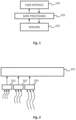
- Fig. 1 is a rough block diagram of a stove guard comprising a data processing unit 101 and a temperature sensor arrangement 102.
- the data processing unit 101 may be a single processor or microcontroller, or it may consist of a combination of several different processor circuits and additional components needed for their operation.
- a memory and other normal functions related to programmable devices are, in the block diagram of Fig. 1 , arranged in the data processing unit 101 without illustrating them in any more detail.
- the purpose of the temperature sensor arrangement 102 is to receive thermal radiation from objects in a specific field of view and to supply detector signals representative of the received thermal radiation to the data processing unit 101.
- the stove guard also comprises a user interface 103 that, in the block diagram illustrated in Fig. 1 , includes all the elements via which the stove guard receives control commands from a user and gives the user information concerning its operations.
- a simple user interface may include just one or more buttons as well as one or more indicator lights and/or sound indicator devices.
- the user interface 103 may include for example light and/or sound indicator devices via which the data processing unit 101 may give an alarm for the user.
- a more versatile user interface may, for example, be provided with a screen that may be a touch screen, and/or speech recognition and speech synthesizing features.
- the user interface 103 is also considered to include all the elements that the stove guard uses to interact directly with other technical devices. These elements encompass for example controllable relays and corresponding devices via which the stove guard may automatically switch off the functions of the stove, if such devices are included in the arrangement.
- the rough block diagram shown in Fig. 1 does not as such indicate in any way how physically separate units may make up the stove guard as a device, or in which other devices the functions described herein have been partly or fully integrated.
- One possibility is that the intelligence, computation and generation of internal commands for controlling the operations as represented by the data processing unit 101 are implemented in a current control unit located in a suitable place in the vicinity of the stove or elsewhere, but not necessarily so as to be easily accessible to the user.
- the temperature sensor arrangement 102 and the user interface 103 may in this case be located in one or two units that are physically separate from the current control unit and positioned according to their requirements (the temperature sensor arrangement 102 so that its field of view covers the central parts of the stove area; the user interface 103 so that it is easily accessible to the user), for example in a short-range wireless data connection with the current control unit.
- Yet another embodiment is one which, in addition to or instead of a user interface located in the actual stove guard device, involves the use of a wireless connection with the user's terminal device such as a smartphone or a tablet, the user interface being in this case implemented as a programmed process executed by the terminal device.
- the user's terminal device such as a smartphone or a tablet
- the stove guard is considered as a functionality, it is possible to implement one or more of the blocks illustrated in Fig. 1 by using applicable elements of another kitchen device.
- the data processing unit 101 may be fully or partly included in data processing elements that also control other functions of the stove, oven, extractor hood, light fixture or other device.
- Fig. 2 illustrates the principle of a stove guard according to the invention comprising a temperature sensor system including three or more detector elements 201, 202 and 203 having sensitivity bands located at different positions along a thermal radiation wavelength axis.
- the sensitivity band of the detector element does not normally change sharply as a function of the wavelength of radiation, such that, in a literal sense, the sensitivity band does not "begin” at any precisely indicated wavelength value or "end” at one.
- the sensitivity band usually refers to a wavelength range at which the detector element is the most useful.
- One way of defining the limits of the sensitivity band is to use so-called FWHM values (Full Width at Half Maximum), meaning those wavelength values on both sides of the maximum sensitivity at which the sensitivity is half of the maximum.
- Detector element manufacturers typically indicate the sensitivity band of their detector elements as a curve representing external quantum efficiency or the IPCE ratio (Incident Photon to Converted Electron ratio) as percent of the theoretical maximum. Knowing the capacity of other electronics utilizing the signals output by the detector element, it is possible to read from the curve, in a manner that is obvious as such, what wavelength range radiation provides relevant values as measured by this detector element, i.e. what is the utilizable sensitivity band of this detector element.
- the longest-wave detector element 203 may be for example a thermopile sensor provided with a suitable filter and having a sensitivity band of about 3 - 16 micrometres or part of it.
- the detector element 202 for medium waves may be for example an InGaAs photodiode provided with a suitable lens and having a sensitivity band of about 1 - 4 micrometres or part of it.
- the shortest-wave detector element 201 may be for example a silicon or germanium photodiode having a sensitivity band of about 700 - 1000 nanometres or part of it, for example 800 - 900 nanometres.
- thermopile sensor provided with a filter and having a sensitivity band of 6 - 16 micrometres or part of it
- second thermopile sensor provided with a filter and having a sensitivity band of 3 - 6 micrometres or part of it.
- the stove guard according to the invention comprises three or more detector elements.
- the stove guard may also comprise other optical detector elements, such as a photodiode operating in the visible light range (400 - 700 nanometres) or part of it.
- their sensitivity bands are preferably located such that they both extend to a wavelength range of over 1.2 micrometres, or such that one is limited to a wavelength range of less than 1.2 micrometres and the other extends to a wavelength range of over 1.2 micrometres but limited to less than 6 micrometres.
- the sensitivity bands of different detector elements may be located at completely different positions along the optical radiation wavelength axis, as in the example described above (for infrared sensors 3 - 16 micrometres, 1 - 4 micrometres and 700 - 1000 or 800 - 900 nanometres; for the visible light sensor 400 - 700 nanometres).
- the sensitivity bands of at least two detector elements overlie one another at least partly along the optical radiation wavelength axis. They may overlie one another for example in the area of the limit wavelength between them (for example 2-16 micrometres and 1-3 micrometres) or one of them may cover a narrower part of another one's sensitivity band (for example 3-16 micrometres and 6-10 micrometres).
- the data processing unit 101 may be programmed to compare the detector signals output by the different detector elements 201, 202 and 203 to determine the temperature of an object in the field of view, and other information on the object.
- the data processing unit 101 may, for example, detect the absolute magnitude and rate of change of the detector signal output by each detector element. If there is a small object having a quickly rising temperature in the field of view, the detector signal output by the shortest-wave detector element 201 may be assumed to change faster than the detector signals output by the other detector elements 202 and 203.
- One essential advantage in using several wavelength ranges is related to estimating the actual temperature of dishes and food, regardless of differences in other factors, which include emissivity of the surfaces, size and distances of the objects, and shadow areas.
- a cast iron pan is, in terms of its radiation properties, close to the black body of Planck's law.
- Planck's law as the temperature of a body rises, the peak of its emission spectrum moves continuously to a shorter wavelength.
- the black body refers to a body that absorbs all incident radiation without reflecting anything, such that the spectrum of radiation it emits depends only on its own temperature. Planck's law is illustrated in Fig.
- the amount of detectable infrared radiation is, however, also determined to a significant degree by emissivity of the surface of the body in the infrared range.
- the emissivity of stainless steel is markedly lower than that of cast iron.
- the emissivity of different materials may be in different ways wavelength-dependent.
- Fig. 4 illustrates a simplified situation where two bodies at 150 degrees Celsius behave as such according to Planck's law, but one of them has much higher emissivity in the whole infrared range (curve 401) than the other one (curve 402). However, the curve maxima are at the same position of the wavelength axis.
- the vertical dashed lines indicate, by way of example, some wavelength range limits of 2, 5, 13 and 16 micrometres.
- a body having a temperature rising from 50 degrees Celsius to 250 degrees Celsius such that the spectrum of infrared radiation it emits changes from that according to curve 301 to that according to curve 303.
- cf. curve 402 in the field of view of the temperature sensor arrangement of the stove guard there is initially one body at 150 degrees having a low emissivity (cf. curve 402), but another body at 150 degrees having a high emissivity (cf. curve 401) is placed in front of it.
- a stove guard according to the prior art could comprise one wide-band infrared sensor measuring some wavelength band, for example the whole wavelength band from 3 to 16 micrometres.
- the sensor would first measure the amount of radiation between curve 301 and the x-axis in the wavelength range limited by the outermost vertical dashed lines, and then the amount of radiation between curve 303 and the x-axis in the same wavelength range.
- the second example situation it would first measure the amount of radiation between curve 402 and the x-axis, and then the amount of radiation between curve 401 and the x-axis in the above-mentioned wavelength range.
- the stove guard according to the prior art would detect an increase in the measured amount of radiation, regardless of the wavelength range it would measure.
- its data processing unit would have a difficult task to conclude whether the increase in the measured amount of radiation is due to a rise of temperature or some other factor, such as a change in emissivity or distances of the objects in the field of view, or a change in shadow areas.
- the total amount, or even the rate of increase, of infrared radiation received by the stove guard does not as such reliably indicate the temperature of the object, if no other information is provided about the object.
- the stove guard comprising a temperature sensor arrangement including two detector elements may be considered by way of example.
- the sensitivity band of the first one of the detector elements is in this example located in the range of 2-5 micrometres, and the sensitivity band of the second one is located in the range of 13-16 micrometres along the wavelength axis.
- the first detector element would first measure the quite small amount of radiation between curve 301 and the x-axis in the wavelength range limited by the two leftmost vertical dashed lines.
- the second detector element would first measure the amount of radiation between curve 301 and the x-axis in the wavelength range limited by the two rightmost vertical dashed lines.
- the first detector element After the body would have heated up to 250 degrees, the first detector element would measure the much higher amount of radiation between curve 303 and the x-axis between the leftmost vertical dashed lines. Also the amount of radiation measured by the second detector element between curve 303 and the x-axis between the rightmost vertical dashed lines would have increased, but to a relatively much smaller extent.
- the stove guard according to the embodiment of the invention could easily distinguish this situation from the first example situation and conclude that the detected change in the amount of infrared radiation is this time not due to a change in temperature, but to a fact that the emissivity of the surfaces in the field of view or their distance from the detector has changed, the visible portion of the surfaces has increased, new dishes have been placed in the field of view and/or new hotplates have heated to the same temperature as the former ones.
- this critical temperature is normally ca. 240-280 degrees Celsius. Reaching of the critical temperature is a suitable time for a switch-off alarm, so that self-ignition of fat and extremely strong smoking may be prevented.
- the temperature sensor arrangement includes two detector elements, both having a sensitivity band extending to a wavelength range of over 1.2 micrometres (however, the sensitivity bands being different from one another), the comparison as described above may be performed for the suitable wavelength ranges in terms of the temperatures of interest.
- Unwanted radiation that is non-related to the intended operation of the stove guard such as sunlight and intense light from certain artificial light sources may interfere with the measurement results in the shorter and medium wavelength ranges of the temperature sensor arrangement.
- information of the shortest wavelength range or ranges may be used to cancel this interference in the medium wavelength range.
- a sensor for a wavelength range of 800-900 nanometres or a sensor for the visible light range (400-700 nanometres) may be used to detect radiation changes originating from sunlight, artificial light or other sources non-related to the temperature changes in the stove area.
- the correction may be made for example by detecting the forms of the changes in the signals and by cancelling, from the medium range sensor signal, the changes having the same form as detected in the short range signals.
- the shortest wavelength range may be only intended for correcting the medium range, such that the shortest range signal is subtracted from the medium range signal, multiplied by a suitable, possibly automatically adaptable factor.
- the short wavelength detector element a wavelength range that is close to visible light, i.e. less than 1.2 micrometres. It is advantageously located right adjacent to, or so as to slightly overlap the sensitivity band of the medium wavelength detector element.
- the lower limit of the sensitivity band is in practice about one micrometre or, at the lowest, 0.9 micrometres.
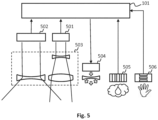
- Fig. 5 schematically presents the sensor and data processing elements of one stove guard.
- the stove guard comprises a data processing unit 101 and its temperature sensor arrangement includes a first detector element 501 and a second detector element 502. It also includes an optic generally indicated in Fig. 5 by reference numeral 503, the optic being arranged to direct, to the first detector element 501, thermal radiation of a different wavelength range than to the second detector element 502.
- This type of optic may be used as an addition or an alternative to the configuration where the detector elements 501 and 502 are based on different detector technologies.
- filtering of thermal radiation such that its spectrum is restricted is known as such, and it is therefore not necessary to discuss herein in any more detail what kinds of filters the optic 503 may possibly contain.
- the optic 503 is further arranged to direct, to the first detector element 501, thermal radiation from a narrower part of the field of view than to the second detector element 502.
- thermal radiation is directed to the first detector element 501 via a relatively directional lens arrangement and to the second detector element 502 via a wider lens arrangement, such that the field of view of the first detector element 501 forms a relatively narrow beam. It may be preferably located in the mid-area of the total field of view of the temperature sensor arrangement as a whole, but it is also possible to implement an arrangement where the field of view of the narrow-beam detector element is directed some other way.
- the detector elements for different wavelength ranges are intended to directly cancel each other's signals, it is advantageous to arrange the optic and possible limiters such that their beams and sensitivity ranges are as similar as possible.
- the conventional detector elements used for detecting thermal radiation are based on detecting the total amount of thermal radiation of a specific frequency, i.e. wavelength range (for example wavelengths of 4 - 16 micrometres) at a specific solid angle. If merely the detector signal output by the second detector element 502 was taken into consideration, it could be possible that one very hot object, such as a mistakenly switched-on hotplate, would provide a similar detector signal as a number of only reasonably hot objects over a wider area. In other words, the stove guard would not necessarily be able to reliably distinguish a dangerous situation (one overheated hotplate) from a normal situation (food being cooked on several hotplates).
- the data processing unit 101 may be programmed to compare the detector signals output by the first detector element 501 and the second detector element 502 to determine whether the temperature measured by the first detector element 501 is different from that measured by the second detector element 502. If there is a marked difference between the temperatures measured by the detector elements 501 and 502, and further the temperature of the object as measured by either one of the detector elements is higher than a predetermined threshold value, it is likely that there is, in the field of view, a hot object so small that it only falls within the field of view of either one of the detector elements.
- the data processing unit 101 may be programmed to generate an alarm in response to this type of finding. As discussed above, the data processing unit 101 may additionally or alternatively be programmed to generate an alarm in response to detecting that the amount of the received thermal radiation as measured by the first detector element 501 has changed in a markedly different proportion to that measured by the second detector element 502.
- the data processing unit 101 is generally programmed to execute algorithms, even complex ones, taking into consideration not only the momentary value of the detector signals but also the recent variation history and/or longer trends of the values and/or prior situations that resulted in alarms and the user's reactions to such situations.
- FIG. 5 Other elements illustrated as an example regarding the sensors and components of the stove guard of Fig. 5 include an optical transmitter 504, a humidity sensor 505 and a proximity sensor 506.
- the stove guard or at least its temperature sensor arrangement may be an integrated part of an extractor hood, a stove, an oven or other home appliance.
- the elements of the stove guard that would be integrated into a specific home appliance such as extractor hood may be built to the same size and shape as a light module that would be used in that home appliance to illuminate the stove and/or its vicinity.
- This arrangement provides a lighting-technical advantage, because all other elements used by the home appliance manufacturer in the assembly stage may the same, irrespective of whether an integrated stove guard or a regular light module is installed in the home appliance in question.
- the integratable stove guard may be installed in place already in connection with assembly or it may be inserted to replace a previously installed light module at a later time.
- the integratable stove guard may itself also include light sources, so the fact of whether there is only a light module or an integrated stove guard in a specific part of the home appliance does not affect the lighting of the stove and its vicinity.
- the stove guard may comprise a proximity sensor 506 arranged to measure the proximity of an object external of the stove guard and to supply object information corresponding to the measured proximity of the external object to the data processing unit 101.
- the data processing unit 101 may then be programmed to identify whether a change in radiation received from an object in the field of view takes place simultaneously with the measured proximity of the external object.
- the data processing unit 101 may be programmed to generate an alarm in response to detecting that the change in radiation received from the object in the field of view does not take place simultaneously with the measured proximity of the external object.
Landscapes
- Physics & Mathematics (AREA)
- General Physics & Mathematics (AREA)
- Engineering & Computer Science (AREA)
- Spectroscopy & Molecular Physics (AREA)
- Chemical & Material Sciences (AREA)
- Combustion & Propulsion (AREA)
- Mechanical Engineering (AREA)
- General Engineering & Computer Science (AREA)
- Business, Economics & Management (AREA)
- Emergency Management (AREA)
- Photometry And Measurement Of Optical Pulse Characteristics (AREA)
- Radiation Pyrometers (AREA)
Claims (12)
- Ofenschutz, umfassend eine Datenverarbeitungseinheit (101) und eine Temperatursensoranordnung (102) zum Empfangen von thermischer Strahlung von Objekten in einem spezifischen Gesichtsfeld und zum Bereitstellen von Detektorsignalen, die für die empfangene thermische Strahlung repräsentativ sind, an die Datenverarbeitungseinheit (101), wobei:- die Temperatursensoranordnung wenigstens drei Detektorelemente (201, 202, 203) umfasst, deren Empfindlichkeitsbänder an unterschiedlichen Positionen entlang einer optischen Strahlungswellenlängenachse lokalisiert sind, und- das Empfindlichkeitsband von einem der Detektorelemente (201, 202, 203) auf einen Wellenlängenbereich von weniger als 1,2 Mikrometer begrenzt ist;wobei die Verarbeitungseinheit (101) dazu konfiguriert ist, den Zeitpunkt zu identifizieren, wenn ein Objekt in dem Gesichtsfeld der Temperatursensoranordnung eine spezifische Absoluttemperatur überschreitet, durch Vergleichen von empfangener thermischer Strahlung in denjenigen der Empfindlichkeitsbänder, die unterschiedlichen - relativ zueinander - Wellenlängenbereichen entsprechen, die sich über 1,2 Mikrometer erstrecken, sowie ihrer relativen Änderungsraten,dadurch gekennzeichnet, dass die Verarbeitungseinheit (101) konfiguriert ist zur Verwendung von Informationen von empfangener Strahlung in dem Empfindlichkeitsband von weniger als 1,2 Mikrometer von dem Detektorelement, das ein Empfindlichkeitsband hat, das auf einen Wellenlängenbereich von weniger als 1,2 Mikrometer begrenzt ist, um eine Interferenz zu löschen, die durch unerwünschte Strahlung ohne Bezug zum Betrieb des Ofenschutzes verursacht wird, wobei die Messergebnisse von wenigstens einem der Detektorelemente ein Empfindlichkeitsband haben, das sich zu einem Wellenlängenbereich von über 1,2 Mikrometer erstreckt.
- Ofenschutz nach Anspruch 1,dadurch gekennzeichnet, dass die Detektorelemente ein Detektorelement für kurze Wellenlänge und ein Detektorelement für mittlere Wellenlänge umfassen, wobei- das Detektorelement mit dem Empfindlichkeitsband von weniger als 1,2 Mikrometer das Detektorelement für kurze Wellenlänge ist,- und wobei eines der Detektorelemente mit dem Empfindlichkeitsband, das sich über 1,2 Mikrometer erstreckt, das Detektorelement für mittlere Wellenlänge ist, wobeidas Empfindlichkeitsband des Detektorelements für mittlere Wellenlänge an das Empfindlichkeitsband des Detektorelements für kurze Wellenlänge angrenzt oder damit überlappt und sich am kürzesten Ende auf nicht kürzer als 0,9 Mikrometer erstreckt.
- Ofenschutz nach einem der Ansprüche 1 bis 3, dadurch gekennzeichnet, dass wenigstens zwei von den Detektorelementen auf unterschiedlichen Detektortechnologien basieren.
- Ofenschutz nach Anspruch 3, dadurch gekennzeichnet, dass die Detektortechnologien wenigstens zwei von den Folgenden umfassen: einen Thermosäulensensor, eine InGaAs-Fotodiode, eine Silizium-Fotodiode, eine Germanium-Fotodiode.
- Ofenschutz nach Anspruch 4, dadurch gekennzeichnet, dass die Detektortechnologien wenigstens umfassen:- einen Thermosäulensensor, der ein Empfindlichkeitsband von 3 bis 16 Mikrometer oder einen Teil davon hat, und- eine InGaAs-Fotodiode, die ein Empfindlichkeitsband von 0,9 bis 4 Mikrometer oder einen Teil davon hat.
- Ofenschutz nach Anspruch 4, dadurch gekennzeichnet, dass die Detektortechnologien wenigstens umfassen:- einen ersten Thermosäulensensor, der mit einem Filter versehen ist und ein Empfindlichkeitsband von 6 bis 16 Mikrometer oder einen Teil davon hat, und- einen zweiten Thermosäulensensor, der mit einem Filter versehen ist und ein Empfindlichkeitsband von 3 bis 6 Mikrometer oder einen Teil davon hat.
- Ofenschutz nach Anspruch 5 oder 6, dadurch gekennzeichnet, dass die Detektortechnologien ferner umfassen:- eine Silizium-Fotodiode, die ein Empfindlichkeitsband von 800 bis 900 Nanometer oder einen Teil davon hat.
- Ofenschutz nach einem der Ansprüche 5 bis 7, dadurch gekennzeichnet, dass die Detektortechnologien ferner umfassen:- eine Fotodiode für sichtbares Licht, die ein Empfindlichkeitsband von 400 bis 700 Nanometer oder einen Teil davon hat.
- Ofenschutz nach einem der vorhergehenden Ansprüche, dadurch gekennzeichnet, dass- der Ofenschutz eine Optik (503) umfasst, die dazu ausgelegt ist, optische Strahlung zu einem ersten Detektorelement (501) mit einem unterschiedlichen Wellenlängenbereich als zu einem zweiten Detektorelement (502) zu lenken.
- Ofenschutz nach einem der vorhergehenden Ansprüche, dadurch gekennzeichnet, dass die Datenverarbeitungseinheit (101) dazu programmiert ist, einen Alarm in Antwort auf eine Detektion zu generieren, dass die Temperatur eines Objekts, gemessen durch ein erstes Detektorelement (501), erheblich verschieden ist von jener, die durch ein zweites Detektorelement (502) gemessen wird, und die Temperatur des Objekts, die durch irgendeines der Detektorelemente gemessen wird, höher als ein vorbestimmter Schwellenwert ist.
- Ofenschutz nach einem der vorhergehenden Ansprüche, dadurch gekennzeichnet, dass die Datenverarbeitungseinheit (101) dazu programmiert ist, einen Alarm in Antwort auf eine Detektion zu generieren, dass die Menge der empfangenen thermischen Strahlung, die durch ein erstes Detektorelement (501) gemessen wird, sich in einem erheblich anderen Verhältnis als jene verändert hat, die durch ein zweites Detektorelement (502) gemessen wird.
- Ofenschutz nach einem der vorhergehenden Ansprüche, dadurch gekennzeichnet, dass- der Ofenschutz einen Nähesensor (506) umfasst, der dazu ausgelegt ist, die Nähe eines Objekts außerhalb des Ofenschutzes zu messen und Objektinformationen entsprechend der gemessenen Nähe des externen Objekts an die Datenverarbeitungseinheit (101) bereitzustellen,- die Datenverarbeitungseinheit (101) dazu programmiert ist zu identifizieren, ob eine Veränderung in der Strahlung, die von einem Objekt in dem Gesichtsfeld empfangen wird, gleichzeitig mit der gemessenen Nähe des externen Objekts erfolgt, und- die Datenverarbeitungseinheit (101) dazu programmiert ist, einen Alarm in Antwort auf eine Detektion zu generieren, dass die Änderung der Strahlung, die von dem Objekt in dem Gesichtsfeld empfangen wird, nicht gleichzeitig mit der gemessenen Nähe des externen Objekts erfolgt.
Applications Claiming Priority (1)
| Application Number | Priority Date | Filing Date | Title |
|---|---|---|---|
| FI20185482A FI131067B1 (fi) | 2018-05-25 | 2018-05-25 | Liesivahti, joka hyödyntää eri aallonpituuksia |
Publications (3)
| Publication Number | Publication Date |
|---|---|
| EP3572777A1 EP3572777A1 (de) | 2019-11-27 |
| EP3572777C0 EP3572777C0 (de) | 2024-10-09 |
| EP3572777B1 true EP3572777B1 (de) | 2024-10-09 |
Family
ID=66625845
Family Applications (1)
| Application Number | Title | Priority Date | Filing Date |
|---|---|---|---|
| EP19175617.0A Active EP3572777B1 (de) | 2018-05-25 | 2019-05-21 | Ofenschutz mit verwendung verschiedener wellenlängen |
Country Status (3)
| Country | Link |
|---|---|
| US (1) | US11248964B2 (de) |
| EP (1) | EP3572777B1 (de) |
| FI (1) | FI131067B1 (de) |
Families Citing this family (3)
| Publication number | Priority date | Publication date | Assignee | Title |
|---|---|---|---|---|
| JP7594186B2 (ja) * | 2021-03-19 | 2024-12-04 | 日本製鉄株式会社 | 温度測定装置及び温度測定方法 |
| JP2024518935A (ja) | 2021-05-07 | 2024-05-08 | トリナミクス ゲゼルシャフト ミット ベシュレンクテル ハフツング | 放射線放出素子の放射温度を監視する装置及び方法 |
| CN117295931A (zh) | 2021-05-07 | 2023-12-26 | 特里纳米克斯股份有限公司 | 用于监测辐射发射元件的发射温度的装置和方法 |
Family Cites Families (35)
| Publication number | Priority date | Publication date | Assignee | Title |
|---|---|---|---|---|
| US3415994A (en) * | 1966-10-28 | 1968-12-10 | Navy Usa | Dual element infrared detector |
| SE8402344L (sv) | 1984-04-30 | 1985-12-08 | Arnold Ingemar Magnusson | Overhettningsalarm |
| JPS62126589A (ja) * | 1985-11-26 | 1987-06-08 | 株式会社東芝 | 電子レンジの安全装置 |
| EP0419046B1 (de) * | 1989-08-23 | 1997-05-28 | Japan Energy Corporation | Feueralarmsystem sowie Verfahren dazu und Umgebungsmonitor |
| US6299920B1 (en) * | 1998-11-05 | 2001-10-09 | Premark Feg L.L.C. | Systems and method for non-invasive assessment of cooked status of food during cooking |
| JP3969986B2 (ja) | 2001-09-28 | 2007-09-05 | 大阪瓦斯株式会社 | クッキングヒータ装置 |
| US6618687B2 (en) * | 2001-10-16 | 2003-09-09 | The United States Of America As Represented By The Secretary Of The Navy | Temperature-based estimation of remaining absorptive capacity of a gas absorber |
| US7068177B2 (en) * | 2002-09-19 | 2006-06-27 | Honeywell International, Inc. | Multi-sensor device and methods for fire detection |
| US7745759B2 (en) * | 2003-02-06 | 2010-06-29 | Edgecraft Corporation | Apparatus for brewing beverages |
| US7265350B2 (en) * | 2004-03-03 | 2007-09-04 | Advanced Biophotonics, Inc. | Integrated multi-spectral imaging systems and methods of tissue analyses using same |
| DE102004023846A1 (de) * | 2004-05-13 | 2005-12-08 | BSH Bosch und Siemens Hausgeräte GmbH | Temperatursensor für ein Gargerät, Gargerät mit elektronischer Temperaturregelung und Verfahren zur Temperaturerfassung |
| US20050265423A1 (en) * | 2004-05-26 | 2005-12-01 | Mahowald Peter H | Monitoring system for cooking station |
| US7591583B2 (en) * | 2005-05-18 | 2009-09-22 | Federal-Mogul World Wide, Inc. | Transient defect detection algorithm |
| US20060278897A1 (en) * | 2005-06-10 | 2006-12-14 | Heller Donald F | Multispectral Energy/Power Meter For Laser Sources |
| US7239974B2 (en) * | 2005-11-21 | 2007-07-03 | Viaspace Security Inc. | Explosive device detection based on differential emissivity |
| CA2641568C (en) * | 2006-02-07 | 2014-01-28 | Matsushita Electric Industrial Co., Ltd. | Induction heating cooking device |
| JP4989264B2 (ja) * | 2007-03-16 | 2012-08-01 | 大阪瓦斯株式会社 | 加熱調理器用の温度検出装置 |
| US7771113B2 (en) * | 2007-06-29 | 2010-08-10 | Cummins Filtration Ip, Inc | Sensor rationality diagnostic |
| FI121608B (fi) | 2008-07-04 | 2011-01-31 | Safera Oy | Liesiturvajärjestelmä |
| JP5272931B2 (ja) * | 2009-07-03 | 2013-08-28 | パナソニック株式会社 | 電気湯沸かし器 |
| DE102011081303A1 (de) * | 2011-08-22 | 2013-02-28 | BSH Bosch und Siemens Hausgeräte GmbH | Überwachungsvorrichtung für Kochfelder |
| US9411137B2 (en) * | 2011-09-26 | 2016-08-09 | Raytheon Company | Ultra compact inverse telephoto optical system for use in the IR spectrum |
| US20130340500A1 (en) * | 2012-06-21 | 2013-12-26 | Craig Miller | Sensor systems and monitoring systems |
| EP2704521B1 (de) * | 2012-09-03 | 2020-10-14 | BSH Hausgeräte GmbH | Hausgerätevorrichtung |
| US9729803B2 (en) * | 2013-03-15 | 2017-08-08 | Infrared Integrated Systems, Ltd. | Apparatus and method for multispectral imaging with parallax correction |
| US20150185767A1 (en) * | 2013-12-27 | 2015-07-02 | Arvind S. | Electronic devices with integrated lenses |
| CN106157520B (zh) | 2015-04-21 | 2018-08-14 | 信泰光学(深圳)有限公司 | 主动防护系统 |
| US10554897B2 (en) * | 2015-10-16 | 2020-02-04 | Honeywell International Inc. | Method and system for adjusting the field of view of a flame detector |
| KR102311356B1 (ko) * | 2017-03-20 | 2021-10-12 | 오와이 할튼 그룹 엘티디. | 화재안전장치 방법 및 시스템 |
| US11765323B2 (en) * | 2017-05-26 | 2023-09-19 | Calumino Pty Ltd. | Apparatus and method of location determination in a thermal imaging system |
| EP3641496A4 (de) * | 2017-06-16 | 2020-06-24 | Mitsubishi Electric Corporation | Kochgerät für induktionserhitzung und sensoreinheit |
| US10810860B1 (en) * | 2018-01-03 | 2020-10-20 | Objectvideo Labs, Llc | Intelligent vent hood |
| FI127878B (fi) * | 2018-01-09 | 2019-04-30 | Safera Oy | Liesivahti, joka hyödyntää laajaa näkökenttää |
| CN108282641A (zh) * | 2018-03-22 | 2018-07-13 | 深圳市邻友通科技发展有限公司 | 监控设备、监控基站和监控系统 |
| US11517146B2 (en) * | 2019-05-21 | 2022-12-06 | Whirlpool Corporation | Cooking assistance appliance |
-
2018
- 2018-05-25 FI FI20185482A patent/FI131067B1/fi active
-
2019
- 2019-05-21 EP EP19175617.0A patent/EP3572777B1/de active Active
- 2019-05-24 US US16/422,354 patent/US11248964B2/en active Active
Also Published As
| Publication number | Publication date |
|---|---|
| EP3572777C0 (de) | 2024-10-09 |
| US11248964B2 (en) | 2022-02-15 |
| FI131067B1 (fi) | 2024-08-29 |
| EP3572777A1 (de) | 2019-11-27 |
| US20190360866A1 (en) | 2019-11-28 |
| FI20185482A1 (fi) | 2019-11-26 |
Similar Documents
| Publication | Publication Date | Title |
|---|---|---|
| EP1094688B1 (de) | Kochfeld und Überwachungssystem, versehen mit der Erfassung von Kennmerken eines Küchengeräts durch ein festes oberflächiges Kochfeld | |
| EP3572777B1 (de) | Ofenschutz mit verwendung verschiedener wellenlängen | |
| FI127878B (fi) | Liesivahti, joka hyödyntää laajaa näkökenttää | |
| US6384384B1 (en) | Boil dry detection in cooking appliances | |
| US6169486B1 (en) | Monitoring and control system for monitoring the temperature of a glass ceramic cooktop | |
| US6452136B1 (en) | Monitoring and control system and method for sensing of a vessel and other properties of a cooktop | |
| US6225607B1 (en) | Sensor-controlled cooktop with a sensor unit arranged below the cooktop plate | |
| JP3969986B2 (ja) | クッキングヒータ装置 | |
| JP5247914B1 (ja) | 加熱調理器 | |
| JP2024519730A (ja) | 放射線放出素子の放射温度を監視する装置及び方法 | |
| JP4381918B2 (ja) | 誘導加熱調理器 | |
| KR20240007148A (ko) | 복사 방출 요소의 방출 온도를 모니터링하는 디바이스 및 방법 | |
| JP5209399B2 (ja) | 誘導加熱調理器 | |
| JP4989264B2 (ja) | 加熱調理器用の温度検出装置 | |
| JP4443947B2 (ja) | 誘導加熱調理器 | |
| JP4497225B2 (ja) | 誘導加熱調理器 | |
| JP5848082B2 (ja) | 炎感知器及び炎判定方法 | |
| US20040239511A1 (en) | Fire hazard prevention system | |
| JP4356394B2 (ja) | 誘導加熱調理器 | |
| JP2008262933A (ja) | 誘導加熱調理器 | |
| EP3013121B1 (de) | Induktionsherd | |
| CN220819228U (zh) | 红外测温模组及感应烹饪器具 | |
| JP4496998B2 (ja) | 誘導加熱調理器 | |
| JP2009301878A (ja) | 誘導加熱調理器 | |
| CN111096070B (zh) | 具有温度探测器的家用电器 |
Legal Events
| Date | Code | Title | Description |
|---|---|---|---|
| PUAI | Public reference made under article 153(3) epc to a published international application that has entered the european phase |
Free format text: ORIGINAL CODE: 0009012 |
|
| STAA | Information on the status of an ep patent application or granted ep patent |
Free format text: STATUS: THE APPLICATION HAS BEEN PUBLISHED |
|
| AK | Designated contracting states |
Kind code of ref document: A1 Designated state(s): AL AT BE BG CH CY CZ DE DK EE ES FI FR GB GR HR HU IE IS IT LI LT LU LV MC MK MT NL NO PL PT RO RS SE SI SK SM TR |
|
| AX | Request for extension of the european patent |
Extension state: BA ME |
|
| STAA | Information on the status of an ep patent application or granted ep patent |
Free format text: STATUS: REQUEST FOR EXAMINATION WAS MADE |
|
| 17P | Request for examination filed |
Effective date: 20200424 |
|
| RBV | Designated contracting states (corrected) |
Designated state(s): AL AT BE BG CH CY CZ DE DK EE ES FI FR GB GR HR HU IE IS IT LI LT LU LV MC MK MT NL NO PL PT RO RS SE SI SK SM TR |
|
| STAA | Information on the status of an ep patent application or granted ep patent |
Free format text: STATUS: EXAMINATION IS IN PROGRESS |
|
| 17Q | First examination report despatched |
Effective date: 20210224 |
|
| GRAP | Despatch of communication of intention to grant a patent |
Free format text: ORIGINAL CODE: EPIDOSNIGR1 |
|
| STAA | Information on the status of an ep patent application or granted ep patent |
Free format text: STATUS: GRANT OF PATENT IS INTENDED |
|
| INTG | Intention to grant announced |
Effective date: 20240522 |
|
| GRAS | Grant fee paid |
Free format text: ORIGINAL CODE: EPIDOSNIGR3 |
|
| GRAA | (expected) grant |
Free format text: ORIGINAL CODE: 0009210 |
|
| STAA | Information on the status of an ep patent application or granted ep patent |
Free format text: STATUS: THE PATENT HAS BEEN GRANTED |
|
| AK | Designated contracting states |
Kind code of ref document: B1 Designated state(s): AL AT BE BG CH CY CZ DE DK EE ES FI FR GB GR HR HU IE IS IT LI LT LU LV MC MK MT NL NO PL PT RO RS SE SI SK SM TR |
|
| REG | Reference to a national code |
Ref country code: CH Ref legal event code: EP |
|
| REG | Reference to a national code |
Ref country code: DE Ref legal event code: R096 Ref document number: 602019059940 Country of ref document: DE |
|
| REG | Reference to a national code |
Ref country code: IE Ref legal event code: FG4D |
|
| U01 | Request for unitary effect filed |
Effective date: 20241031 |
|
| U07 | Unitary effect registered |
Designated state(s): AT BE BG DE DK EE FI FR IT LT LU LV MT NL PT RO SE SI Effective date: 20241112 |
|
| PG25 | Lapsed in a contracting state [announced via postgrant information from national office to epo] |
Ref country code: HR Free format text: LAPSE BECAUSE OF FAILURE TO SUBMIT A TRANSLATION OF THE DESCRIPTION OR TO PAY THE FEE WITHIN THE PRESCRIBED TIME-LIMIT Effective date: 20241009 Ref country code: IS Free format text: LAPSE BECAUSE OF FAILURE TO SUBMIT A TRANSLATION OF THE DESCRIPTION OR TO PAY THE FEE WITHIN THE PRESCRIBED TIME-LIMIT Effective date: 20250209 |
|
| PG25 | Lapsed in a contracting state [announced via postgrant information from national office to epo] |
Ref country code: ES Free format text: LAPSE BECAUSE OF FAILURE TO SUBMIT A TRANSLATION OF THE DESCRIPTION OR TO PAY THE FEE WITHIN THE PRESCRIBED TIME-LIMIT Effective date: 20241009 |
|
| PG25 | Lapsed in a contracting state [announced via postgrant information from national office to epo] |
Ref country code: GR Free format text: LAPSE BECAUSE OF FAILURE TO SUBMIT A TRANSLATION OF THE DESCRIPTION OR TO PAY THE FEE WITHIN THE PRESCRIBED TIME-LIMIT Effective date: 20250110 |
|
| PG25 | Lapsed in a contracting state [announced via postgrant information from national office to epo] |
Ref country code: PL Free format text: LAPSE BECAUSE OF FAILURE TO SUBMIT A TRANSLATION OF THE DESCRIPTION OR TO PAY THE FEE WITHIN THE PRESCRIBED TIME-LIMIT Effective date: 20241009 |
|
| PG25 | Lapsed in a contracting state [announced via postgrant information from national office to epo] |
Ref country code: RS Free format text: LAPSE BECAUSE OF FAILURE TO SUBMIT A TRANSLATION OF THE DESCRIPTION OR TO PAY THE FEE WITHIN THE PRESCRIBED TIME-LIMIT Effective date: 20250109 |
|
| U20 | Renewal fee for the european patent with unitary effect paid |
Year of fee payment: 7 Effective date: 20250516 |
|
| PG25 | Lapsed in a contracting state [announced via postgrant information from national office to epo] |
Ref country code: SM Free format text: LAPSE BECAUSE OF FAILURE TO SUBMIT A TRANSLATION OF THE DESCRIPTION OR TO PAY THE FEE WITHIN THE PRESCRIBED TIME-LIMIT Effective date: 20241009 |
|
| PGFP | Annual fee paid to national office [announced via postgrant information from national office to epo] |
Ref country code: GB Payment date: 20250519 Year of fee payment: 7 |
|
| PGFP | Annual fee paid to national office [announced via postgrant information from national office to epo] |
Ref country code: NO Payment date: 20250519 Year of fee payment: 7 |
|
| PG25 | Lapsed in a contracting state [announced via postgrant information from national office to epo] |
Ref country code: SK Free format text: LAPSE BECAUSE OF FAILURE TO SUBMIT A TRANSLATION OF THE DESCRIPTION OR TO PAY THE FEE WITHIN THE PRESCRIBED TIME-LIMIT Effective date: 20241009 |
|
| PG25 | Lapsed in a contracting state [announced via postgrant information from national office to epo] |
Ref country code: CZ Free format text: LAPSE BECAUSE OF FAILURE TO SUBMIT A TRANSLATION OF THE DESCRIPTION OR TO PAY THE FEE WITHIN THE PRESCRIBED TIME-LIMIT Effective date: 20241009 |
|
| PLBE | No opposition filed within time limit |
Free format text: ORIGINAL CODE: 0009261 |
|
| STAA | Information on the status of an ep patent application or granted ep patent |
Free format text: STATUS: NO OPPOSITION FILED WITHIN TIME LIMIT |
|
| 26N | No opposition filed |
Effective date: 20250710 |
|
| REG | Reference to a national code |
Ref country code: CH Ref legal event code: H13 Free format text: ST27 STATUS EVENT CODE: U-0-0-H10-H13 (AS PROVIDED BY THE NATIONAL OFFICE) Effective date: 20251223 |
|
| PG25 | Lapsed in a contracting state [announced via postgrant information from national office to epo] |
Ref country code: CH Free format text: LAPSE BECAUSE OF NON-PAYMENT OF DUE FEES Effective date: 20250531 |
|
| PG25 | Lapsed in a contracting state [announced via postgrant information from national office to epo] |
Ref country code: MC Free format text: LAPSE BECAUSE OF FAILURE TO SUBMIT A TRANSLATION OF THE DESCRIPTION OR TO PAY THE FEE WITHIN THE PRESCRIBED TIME-LIMIT Effective date: 20241009 |
|
| PG25 | Lapsed in a contracting state [announced via postgrant information from national office to epo] |
Ref country code: IE Free format text: LAPSE BECAUSE OF NON-PAYMENT OF DUE FEES Effective date: 20250521 |