EP3572823B1 - Système dissocié d'imagerie par résonance magnétique - Google Patents
Système dissocié d'imagerie par résonance magnétique Download PDFInfo
- Publication number
- EP3572823B1 EP3572823B1 EP19166735.1A EP19166735A EP3572823B1 EP 3572823 B1 EP3572823 B1 EP 3572823B1 EP 19166735 A EP19166735 A EP 19166735A EP 3572823 B1 EP3572823 B1 EP 3572823B1
- Authority
- EP
- European Patent Office
- Prior art keywords
- mri
- buttress
- magnet housing
- mri magnet
- assemblies
- Prior art date
- Legal status (The legal status is an assumption and is not a legal conclusion. Google has not performed a legal analysis and makes no representation as to the accuracy of the status listed.)
- Active
Links
Images




Classifications
-
- G—PHYSICS
- G01—MEASURING; TESTING
- G01R—MEASURING ELECTRIC VARIABLES; MEASURING MAGNETIC VARIABLES
- G01R33/00—Arrangements or instruments for measuring magnetic variables
- G01R33/20—Arrangements or instruments for measuring magnetic variables involving magnetic resonance
- G01R33/28—Details of apparatus provided for in groups G01R33/44 - G01R33/64
- G01R33/38—Systems for generation, homogenisation or stabilisation of the main or gradient magnetic field
- G01R33/3806—Open magnet assemblies for improved access to the sample, e.g. C-type or U-type magnets
-
- A—HUMAN NECESSITIES
- A61—MEDICAL OR VETERINARY SCIENCE; HYGIENE
- A61B—DIAGNOSIS; SURGERY; IDENTIFICATION
- A61B5/00—Measuring for diagnostic purposes; Identification of persons
- A61B5/05—Detecting, measuring or recording for diagnosis by means of electric currents or magnetic fields; Measuring using microwaves or radio waves
- A61B5/055—Detecting, measuring or recording for diagnosis by means of electric currents or magnetic fields; Measuring using microwaves or radio waves involving electronic [EMR] or nuclear [NMR] magnetic resonance, e.g. magnetic resonance imaging
-
- A—HUMAN NECESSITIES
- A61—MEDICAL OR VETERINARY SCIENCE; HYGIENE
- A61N—ELECTROTHERAPY; MAGNETOTHERAPY; RADIATION THERAPY; ULTRASOUND THERAPY
- A61N5/00—Radiation therapy
- A61N5/10—X-ray therapy; Gamma-ray therapy; Particle-irradiation therapy
- A61N5/1048—Monitoring, verifying, controlling systems and methods
- A61N5/1049—Monitoring, verifying, controlling systems and methods for verifying the position of the patient with respect to the radiation beam
-
- G—PHYSICS
- G01—MEASURING; TESTING
- G01R—MEASURING ELECTRIC VARIABLES; MEASURING MAGNETIC VARIABLES
- G01R33/00—Arrangements or instruments for measuring magnetic variables
- G01R33/20—Arrangements or instruments for measuring magnetic variables involving magnetic resonance
- G01R33/28—Details of apparatus provided for in groups G01R33/44 - G01R33/64
- G01R33/38—Systems for generation, homogenisation or stabilisation of the main or gradient magnetic field
- G01R33/3802—Manufacture or installation of magnet assemblies; Additional hardware for transportation or installation of the magnet assembly or for providing mechanical support to components of the magnet assembly
-
- G—PHYSICS
- G01—MEASURING; TESTING
- G01R—MEASURING ELECTRIC VARIABLES; MEASURING MAGNETIC VARIABLES
- G01R33/00—Arrangements or instruments for measuring magnetic variables
- G01R33/20—Arrangements or instruments for measuring magnetic variables involving magnetic resonance
- G01R33/28—Details of apparatus provided for in groups G01R33/44 - G01R33/64
- G01R33/38—Systems for generation, homogenisation or stabilisation of the main or gradient magnetic field
- G01R33/385—Systems for generation, homogenisation or stabilisation of the main or gradient magnetic field using gradient magnetic field coils
- G01R33/3856—Means for cooling the gradient coils or thermal shielding of the gradient coils
-
- G—PHYSICS
- G01—MEASURING; TESTING
- G01R—MEASURING ELECTRIC VARIABLES; MEASURING MAGNETIC VARIABLES
- G01R33/00—Arrangements or instruments for measuring magnetic variables
- G01R33/20—Arrangements or instruments for measuring magnetic variables involving magnetic resonance
- G01R33/44—Arrangements or instruments for measuring magnetic variables involving magnetic resonance using nuclear magnetic resonance [NMR]
- G01R33/48—NMR imaging systems
- G01R33/4808—Multimodal MR, e.g. MR combined with positron emission tomography [PET], MR combined with ultrasound or MR combined with computed tomography [CT]
-
- A—HUMAN NECESSITIES
- A61—MEDICAL OR VETERINARY SCIENCE; HYGIENE
- A61N—ELECTROTHERAPY; MAGNETOTHERAPY; RADIATION THERAPY; ULTRASOUND THERAPY
- A61N5/00—Radiation therapy
- A61N5/10—X-ray therapy; Gamma-ray therapy; Particle-irradiation therapy
- A61N5/1048—Monitoring, verifying, controlling systems and methods
- A61N5/1049—Monitoring, verifying, controlling systems and methods for verifying the position of the patient with respect to the radiation beam
- A61N2005/1055—Monitoring, verifying, controlling systems and methods for verifying the position of the patient with respect to the radiation beam using magnetic resonance imaging [MRI]
Definitions
- the present application relates to magnetic resonance imaging (MRI) systems, particularly MRI systems that include a split main magnet.
- MRI magnetic resonance imaging
- Magnetic Resonance Imaging (MRI), or nuclear magnetic resonance imaging (NMRI), is primarily a medical imaging technique most commonly used in radiology to visualize the internal structure and function of the body.
- MRI Magnetic Resonance Imaging
- NMRI nuclear magnetic resonance imaging
- MRI is described, for example, by E. MARK HAACKE ET AL., MAGNETIC RESONANCE IMAGING: PHYSICAL PRINCIPLES AND SEQUENCE DESIGN (Wiley-Liss 1999 ).
- U.S. 5,291,169 describes an open architecture Magnetic Resonance Imaging Magnet with a pair of spaced annular superconducting magnet assemblies utilizing a cantilevered main magnet coil and correction magnet coil within each assembly.
- WO 2005/081842 A2 describes a device and a process for performing high temporal- and spatial-resolution MR imaging of the anatomy of a patient during intensity modulated radiation therapy (IMRT) to directly measure and control the highly conformal ionizing radiation dose delivered to the patient for the treatment of diseases caused by proliferative tissue disorders.
- IMRT intensity modulated radiation therapy
- This invention combines the technologies of open MRI, multileaf-collimator or compensating filter-based IMRT delivery and cobalt teletherapy into a single co-registered and gantry mounted system.
- an MRI system having a split MRI configuration that can more easily be relocated and installed compared to prior split MRI systems.
- the disclosed MRI system is preferrably constructed so that it can be disassembled, moved, and then installed into existing facilities and shielded vaults.
- the present invention concerns a magnetic resonance imaging system comprising: a first main MRI magnet disposed within a first MRI magnet housing; a second main MRI magnet disposed within a second MRI magnet housing and separated from the first MRI magnet housing by a gap; a gantry positioned in the gap and supporting a radiation therapy device for delivery of radiotherapy beams; and a plurality of buttress assemblies connecting the first MRI magnet housing and the second MRI magnet housing, wherein at least one of the plurality of buttress assemblies is removably attached to at least one of the first and second MRI magnet housings, wherein the plurality of buttress assemblies extend around the outside of the radiotherapy device clearing the radiation therapy device so that there is no obstruction of the radiotherapy beams delivered by the radiation therapy device, wherein the plurality of buttress assemblies include a first buttress sub-assembly and a second buttress sub-assembly, the first buttress sub-assembly extending radially from the outer surface of the first MRI magnet housing, and the second
- the MRI system can further comprise a cooling system, which can include fluid conduit for carrying coolant for cooling the first and second main MRI magnets.
- the fluid conduit can extend from within the first MRI magnet housing to within the second MRI magnet housing via at least one of the removably attached buttress assemblies.
- the first and second MRI magnet housings can be substantially cylindrical, allowing for accommodating a patient bed within the MRI system for supporting a patient undergoing MRI imaging and/or other medical treatment involving the MRI system.
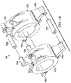
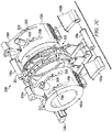
- Figures 1A through 1C show perspective views of a split-magnet MRI system 100.
- Figures 1A shows a fully assembled view of the MRI system 100
- Figure 1B shows a partially exploded view of the MRI system 100
- Figure 1C shows a further exploded view of the MRI system 100.
- the MRI system 100 has a split MRI configuration that can more easily be relocated and installed compared to prior MRI systems.
- the disclosed MRI system 100 is preferrably constructed so that it can be disassembled, moved, and then installed into existing facilities and shielded vaults.
- the MRI system 100 includes first and second cylindrical main MRI magnet housings 102a and 102b for housing respective cylindrical superconducting MRI main magnets 101a and 101b, respectively (shown in Figure 3 ).
- the MRI main magnets 101a and 101b can be operated to produce a uniform magnetic field in a Field-of-View (FOV) for imaging that is generally centered in a gap 104 between the two magnet housings 102a and 102b for imaging a patient positioned on patient bed 103.
- FOV Field-of-View
- the MRI main magnet housings 102a and 102b are supported and connected to each other by buttress assemblies 105a-105c.
- the buttress assemblies 105a-1 05c can connect the MRI main magnets 101a and 101b mechanically, thermally, and/or electronically to improve the performance of the MRI main magnets 101a and 101b and withstand the forces between the main magnets 102a and 102b.
- Buttress assemblies 105a-105c include buttress sub-assemblies 106a-106f, which extend radially out from the magnet housings 102a and 102b, and buttress connectors 108a-108c, which connect respective pairs of the buttress sub-assemblies 106a-106f. More specifically, buttress assembly 105a includes buttress sub-assemblies 106a and 106b connected by buttress connector 108a; buttress assembly 105b includes buttress sub-assemblies 106c and 106d connected by buttress connector 108b; and buttress assembly 105c includes buttress sub-assemblies 106e and 106f connected by buttress connector 108c.
- the buttress sub-assemblies 106a-106d of buttress assemblies 105a and 105b are removable from the magnet housings 102a and 102b, while buttress sub-assemblies 106e and 106f are permanently attached to magnet housings 102a and 102b.
- all three of the buttress connectors 108a-108c are removable from respective buttress sub-assemblies 106a-106f.
- the buttress sub-assemblies 106a-106d arc removably connected to magnet housings 102a and 102b using known removable connection devices, such as known connection hardware that can include, for example, screws and/or nuts and bolts.
- the buttress sub-assemblies 106e and 106f are permanently attached to the magnet housings 102a and 10b, respectively.
- the buttress sub-assemblies 106e and 106f can be welded to the respective magnet housings 102a and 102b, or alternatively attached using adhesives or other permanent attachment means.
- the buttress connectors 108a-108c are removably connected to respective pairs of buttress sub-assemblies 106a-106f using known removable connection devices, such as known connection hardware that can include, for example, screws or nuts and bolts.
- While the illustrated embodiment includes three buttress assemblies 105, of which two include pairs of removable buttress sub-assemblies 106, this is merely one of many possible embodiments.
- Alternative embodiments can include n buttress assemblies 105, where n can be any integer greater than or equal to 2, and where any number from 2 to n of the buttress assemblies 105 can include at least one removable buttress sub-assembly 106.
- alternative embodiments can include any number of buttress assemblies 105, some or all of which can include at least one removable buttress sub-assembly 106.
- the determination as to whether to construct the buttress sub-assemblies 106 to be removably attached to a housing 102 or permanently attached to a housing 102 can be based on achieving a balance among such factors as portability and ease of installation.
- the MRI system 100 can be disassembled into components that are more portable than the fully assembled MRI system 100.
- removable assemblies can add to the steps required for final assembly, so it may be desirable to permanently attach at least some buttress sub-assemblies, such as buttress sub-assemblies 106e and 106f, while making the remaining buttress sub-assemblies 106a-106d removable for improved portability.
- removing laterally-extending buttress sub-assemblies 106a and 106c may allow for the MRI housing 102a and the remaining upwardly-extending buttress sub-assembly 106e to be more easily moved through hallways and doorways of existing structures.
- MRI system 200 can include elements similar to those described in connection with MRI system 100, so like elements have retained like element numbers.
- the MRI system 200 further includes a gantry 202 positioned in the gap 104.
- the gantry 202 is used for supporting a radiation therapy device 204.
- the MRI system 200 can include, for example, a system that is capable of locating the anatomy of interest, imaging to develop a radiation treatment plan, and imaging during radiation treatment to correct the treatment application for patient motion.
- the MRI system 200 can include a radiation source, such as a Co 60 radiation sources or linear electron accelerators (LINAC), supported by a gantry 202 as disclosed in U.S.
- LINAC linear electron accelerators
- Patent Application Publication 2005/0197564 to Dempsey titled “System for Delivering Conformal Radiation Therapy While Simultaneously Imaging Soft Tissue", and/or as disclosed in U.S. Patent Application Publication 2011/0012593 to Shvartsman et al. , titled “Method and Apparatus for Shielding a Linear Accelerator and a Magnetic Resonance Imaging Device From Each Other”.
- the gantry 202 is used for supporting a radiation therapy device 204 in the gap between the pair of MRI main magnets.
- a radiation therapy device 204 positioned in the gap can deliver radiation beams to a radiation therapy isocenter inside the imaging FOV without significant attenuation by the MRI magnets.
- the buttress assemblies 105a-105c extend around the outside of the radiotherapy unit. clearing it so that there is no interference or obstruction of the radiotherapy beams.
- the gantry 202, MRI main magnet housings 102a and 102b, and buttress assemblies 105a-105c of the MRI system are constructed to be capable of being disassembled for ease of installation into existing linear accelerator or cobalt therapy vaults designed for radiation therapy. According to the invention, some or all of the buttress assemblies, or parts thereof, are removable as described above in connection with Figures 1A-1C . For example, there can be n buttress assemblies, where n can be an integer greater than or equal to 2.
- the buttress assemblies can have a cold connection or a room temperature separation support with axial suspension straps 206 to a cryostat.
- the cryostat can be slightly larger in diameter to include this suspcnsion.
- the source of radiation of the radiation therapy device 204 can be, for example, from an accelerator such as a LINAC or from a radioactive source such as Cobalt-60 (60Co).
- the radiation can be delivered in uniform beams or modulated to tailor the radiation as required by the plan. This can include directing the beam, filtering the beam, turning the beam on and off, and shaping the beam with collimators.
- the imaging can take place simultaneously to the radiation delivery to allow for gating the beam on and off to prevent delivery during motion that would compromise the quality of delivery and to volumetrically record the delivery of the radiation dose to the patient's anatomy.
- Prior MRI units with a central gap have not included a radiation treatment device and the support between their magnet halves was close to the imaging volume.
- One of the advantageous features of the disclosed MRI system is a superconducting MRI magnet with a central gap 104 to allow for radiation treatment.
- the disclosed MRI systems 100 and 200 can be configured in various embodiments where various conduits are routed through one or more of the buttress assemblies 105.
- the removable buttress assembly 105a can be used to house electrical and/or fluid conduit that extends between the first and second MRI magnet housings 102a and 102b.
- Various electrical and/or fluid conduits can additionally and/or alternatively be routed through buttress assembly 105b and/or 105c. It should be noted that while Figure 3 shows MRI system 200, the description of Figure 3 can apply equally to MRI system 100.
- the MRI system 200 can include a cooling system 302, which may include, for example, a cryostat.
- the cooling system 302 can include fluid conduit 304 that carrics coolant for cooling the main MRI magnets 101a and 101b.
- the fluid conduit 304 can include a series of connectors 306, which can include any of a variety of known fluid-conduit connectors, at various locations at or near disassembly points of the buttress assembly 105a.
- the MRI system 200 can also include a power/control system 310 that can encompass a variety of electrical and/or control systems, such as controlling the supply of electrical power to the main MRI magnets 101a and 101b during ramp up and ramp down of the MRI magnets 101a and 101b and/or communicating various other operational control signals with the main MRI magnets 101a and 101b.
- the power supply system 310 can include electrical conduit 314 that carries electricity and/or various control signals for powering and/or controlling the operation of the main MRI magnets 101a and 101b.
- the electrical conduit 314 can include a series of connectors 316, which can include any of a variety of known electrical connectors, at various locations at or near disassembly points of the buttress assembly 105a.
- conduit 314 This allows the conduit 314 to be disconnected during the removal and disassembly of the buttress assembly 105a, and then later re-connected during the re-assembly of the buttress assembly 105a and re-connection of the buttress assembly 105a to the main MRI magnet housings 102a and 102b.
- the power/control system 310 can include a single power supply that can be operated to provide electrical operating power to both of the main MRI magnets 101a and 101b.
- the power/control system 310 can include a single power supply that can be operated to provide electrical power during ramp up and ramp down of the operations of the main MRI magnets 101a and 101b.
- each MRI magnet receives electrical power from a respective power supply. During power-up, electrical power is ramped up to each of the MRI magnets most preferrably in a simultaneous manner.
- electrical power is ramped up to each of the MRI magnets most preferrably in a simultaneous manner.
- inhomogeneity in the main magnetic field of the MRI system is caused by differences in electric current to the respective main MRI magnets.
- the electric current should be the same, or very close to the same, in the MRI magnets, so shimming is performed using shim coils that produce magnetic fields for correcting the inhomogeneity in the main magnetic field.
- the present MRI system provides electrical power to both MRI magnets 101a and 101b from a single power supply 310, the differences in electrical current to the two MRI magnets 101a and 101b is greatly reduced, thereby reducing the inhomogeneity in the main magnetic field of the MRI system as compared to prior MRI systems that separately powered each of the MRI magnets. As a result, the present MRI system can be more easily shimmed.
- Embodiments of the MRI systems 100 and 200 can also include various configurations of RF and gradient coils, shown generally as coils 320.
- coils 320 Specific examples and descriptions of coils 320 are disclosed in U.S. Patent Application serial number 12/951,976 to Shvartsman et al. , titled "Self-Shielded Gradient Coil".
- the coils 320 can include gradient coils that include a gap aligned with gap 104 and gantry 202 for preventing attenuation of radiotherapy beams.
- the gradient coils also have a gap in the electronics to prevent attenuating the radiotherapy beam by conducting wires, but have a thin uniformly attenuating former to mechanically support the coils.
- the gradient coils also can have a gap in the electronics of the shield coils, but not the primary coils, to limit attenuating the radiotherapy beam by conducting wires, but can have a compensating material to produce uniform attenuation.
- the gradient coils can also have a gap in the electronics of the shield coils, but not the primary coils to limit attenuating the radiotherapy beam by conducting wires, but can have a compensating material to produce uniform attenuation and a conductor with a lower atomic number, such as Aluminum, to limit attenuation.
- the inside diameters of the main MRI magnets 101a and 101b allows for a radiation source of radiation therapy device 204 to be supported on the gantry 202 at a nominal radius of 1m, which is the preferred distance for present radiation therapy treatment systems.
- the main MRI magnets 101a and 101b can be configured such that the radiotherapy beams emitted by the radiation therapy device 204 do not impinge on the main MRI magnets 101a and 101b on entrance to the MRI system, thereby preventing attenuation and degradation of the radiotherapy beam by scattering on the MRI coils 320.
- the main MRI magnets 101a and 101b and the gradient coils 320 can be configured such that radiotherapy beams emitted by the radiation therapy device 204 do not impinge on the main MRI magnets 101a and 101b or the gradient coils 320 on entrance to the MRI system, preventing attenuation and degradation of the radiotherapy beam by scattering on the MRI coils 320 or the gradient system.
Landscapes
- Physics & Mathematics (AREA)
- Health & Medical Sciences (AREA)
- Life Sciences & Earth Sciences (AREA)
- Nuclear Medicine, Radiotherapy & Molecular Imaging (AREA)
- Condensed Matter Physics & Semiconductors (AREA)
- General Physics & Mathematics (AREA)
- Engineering & Computer Science (AREA)
- General Health & Medical Sciences (AREA)
- Radiology & Medical Imaging (AREA)
- High Energy & Nuclear Physics (AREA)
- Biomedical Technology (AREA)
- Pathology (AREA)
- Animal Behavior & Ethology (AREA)
- Public Health (AREA)
- Veterinary Medicine (AREA)
- Biophysics (AREA)
- Heart & Thoracic Surgery (AREA)
- Medical Informatics (AREA)
- Molecular Biology (AREA)
- Surgery (AREA)
- Theoretical Computer Science (AREA)
- Pulmonology (AREA)
- Magnetic Resonance Imaging Apparatus (AREA)
- Radiation-Therapy Devices (AREA)
Claims (6)
- Système d'imagerie par résonance magnétique (IRM) (100) comprenant :un premier aimant IRM principal (101a) disposé à l'intérieur d'un premier boîtier d'aimant IRM (102a) ;un second aimant IRM principal (101b) disposé à l'intérieur d'un second boîtier d'aimant IRM (102b) et séparé du premier boîtier d'aimant IRM par un espace (104) ;un portique (202) positionné dans l'espace (104) et supportant un dispositif de radiothérapie (204) pour délivrer des faisceaux de radiothérapie ;une pluralité d'ensembles de renfort (105) connectant le premier boîtier d'aimant IRM (102a) et le second boîtier d'aimant IRM (102b),dans lequel au moins l'un de la pluralité d'ensembles de renfort (105) est fixé de manière amovible à au moins l'un des premier (102a) et second (102b) boîtiers d'aimant IRM,dans lequel la pluralité d'ensembles de renfort (105) s'étendent autour de l'extérieur du dispositif de radiothérapie (204) dégageant le dispositif de radiothérapie (204) de sorte qu'il n'y a pas d'obstruction des faisceaux de radiothérapie délivrés par le dispositif de radiothérapie (204),dans lequel la pluralité d'ensembles de renfort comportent un premier sous-ensemble de renfort (106a, c ou e) et un second sous-ensemble de renfort (106b, d ou f), le premier sous-ensemble de renfort (106a, c ou e) s'étendant radialement depuis la surface externe du premier boîtier d'aimant IRM (102a), etle second sous-ensemble de renfort (106b, d ou f) s'étendant radialement depuis la surface externe du second boîtier d'aimant IRM (102b), etdans lequel la pluralité d'ensembles de renfort (105) sont configurés pour permettre le démontage du système d'IRM (100).
- Système d'IRM selon la revendication 1, dans lequel la pluralité d'ensembles de renfort (105) sont connectés de manière amovible à au moins l'un du premier boîtier d'aimant IRM (102a) ou du second boîtier d'aimant IRM (102b) pour permettre le démontage du système d'IRM.
- Système d'IRM selon la revendication 1, dans lequel la pluralité d'ensembles de renfort sont fixés à une surface externe du premier boîtier d'aimant IRM (102a) pour supporter le premier boîtier d'aimant IRM et à une surface externe du second boîtier d'aimant IRM (102b) pour supporter le second boîtier d'aimant IRM.
- Système d'IRM selon la revendication 3, dans lequel le premier sous-ensemble de renfort (106a, c ou e) est connecté de manière amovible à la surface externe du premier boîtier d'aimant IRM ;
le second sous-ensemble de renfort (106b, d ou f) est connecté à la surface externe du second boîtier d'aimant IRM; et l'ensemble de renfort comprenant en outre :
un connecteur de renfort central s'étendant entre et connectant le premier sous-ensemble de renfort et le second sous-ensemble renfort, et qui est connecté de manière amovible auxdits premier et second sous-ensembles de renfort. - Système d'IRM selon la revendication 1, comprenant en outre un système d'alimentation (310), le système d'alimentation comportant un conduit électrique pour fournir de l'énergie électrique aux premier et second aimants IRM principaux, dans lequel le conduit électrique s'étend de l'intérieur du premier boîtier d'aimant IRM jusqu'à l'intérieur du second boîtier d'aimant IRM par acheminement à travers un intérieur d'une partie amovible de la pluralité d'ensembles de renfort.
- Système d'IRM selon la revendication 1, comprenant en outre un système de refroidissement (302) comportant un conduit de fluide pour transporter un liquide de refroidissement pour refroidir le premier aimant IRM principal et le second aimant IRM principal qui traverse l'intérieur d'au moins l'un des ensembles de renfort fixés de manière amovible.
Applications Claiming Priority (3)
| Application Number | Priority Date | Filing Date | Title |
|---|---|---|---|
| US30766510P | 2010-02-24 | 2010-02-24 | |
| PCT/US2011/026073 WO2011106524A1 (fr) | 2010-02-24 | 2011-02-24 | Système dissocié d'imagerie par résonance magnétique |
| EP11748064.0A EP2538840B1 (fr) | 2010-02-24 | 2011-02-24 | Système dissocié d'imagerie par résonance magnétique |
Related Parent Applications (1)
| Application Number | Title | Priority Date | Filing Date |
|---|---|---|---|
| EP11748064.0A Division EP2538840B1 (fr) | 2010-02-24 | 2011-02-24 | Système dissocié d'imagerie par résonance magnétique |
Publications (2)
| Publication Number | Publication Date |
|---|---|
| EP3572823A1 EP3572823A1 (fr) | 2019-11-27 |
| EP3572823B1 true EP3572823B1 (fr) | 2022-04-06 |
Family
ID=44507209
Family Applications (2)
| Application Number | Title | Priority Date | Filing Date |
|---|---|---|---|
| EP19166735.1A Active EP3572823B1 (fr) | 2010-02-24 | 2011-02-24 | Système dissocié d'imagerie par résonance magnétique |
| EP11748064.0A Active EP2538840B1 (fr) | 2010-02-24 | 2011-02-24 | Système dissocié d'imagerie par résonance magnétique |
Family Applications After (1)
| Application Number | Title | Priority Date | Filing Date |
|---|---|---|---|
| EP11748064.0A Active EP2538840B1 (fr) | 2010-02-24 | 2011-02-24 | Système dissocié d'imagerie par résonance magnétique |
Country Status (7)
| Country | Link |
|---|---|
| US (3) | US8803524B2 (fr) |
| EP (2) | EP3572823B1 (fr) |
| JP (2) | JP5827250B2 (fr) |
| CN (2) | CN102781311B (fr) |
| AU (1) | AU2011220724B2 (fr) |
| CA (1) | CA2790572C (fr) |
| WO (1) | WO2011106524A1 (fr) |
Families Citing this family (39)
| Publication number | Priority date | Publication date | Assignee | Title |
|---|---|---|---|---|
| AU2005216070B2 (en) | 2004-02-20 | 2012-01-19 | University Of Florida Research Foundation, Inc. | System for delivering conformal radiation therapy while simultaneously imaging soft tissue |
| EP2443590B1 (fr) * | 2009-06-19 | 2023-06-14 | ViewRay Technologies, Inc. | Système et procédé pour réaliser la reconstruction d'images tomographiques |
| WO2011008969A1 (fr) * | 2009-07-15 | 2011-01-20 | Viewray Incorporated | Procédé et appareil pour blinder un accélérateur linéaire et un dispositif d'imagerie par résonance magnétique l'un de l'autre |
| EP3572823B1 (fr) | 2010-02-24 | 2022-04-06 | ViewRay Technologies, Inc. | Système dissocié d'imagerie par résonance magnétique |
| US8981779B2 (en) | 2011-12-13 | 2015-03-17 | Viewray Incorporated | Active resistive shimming fro MRI devices |
| US10561861B2 (en) | 2012-05-02 | 2020-02-18 | Viewray Technologies, Inc. | Videographic display of real-time medical treatment |
| EP2877089B1 (fr) | 2012-07-27 | 2022-05-18 | University Health Network | Système de radiothérapie intégrant une source de rayonnement avec un appareil d'imagerie par résonance magnétique avec des composants d'aimant mobiles |
| GB201217782D0 (en) * | 2012-10-04 | 2012-11-14 | Tesla Engineering Ltd | Magnet apparatus |
| JP6382208B2 (ja) | 2012-10-26 | 2018-08-29 | ビューレイ・テクノロジーズ・インコーポレイテッドViewRay Technologies, Inc. | システム及びコンピュータプログラム製品 |
| US9404983B2 (en) * | 2013-03-12 | 2016-08-02 | Viewray, Incorporated | Radio frequency transmit coil for magnetic resonance imaging system |
| US9675271B2 (en) * | 2013-03-13 | 2017-06-13 | Viewray Technologies, Inc. | Systems and methods for radiotherapy with magnetic resonance imaging |
| US9289626B2 (en) | 2013-03-13 | 2016-03-22 | Viewray Incorporated | Systems and methods for improved radioisotopic dose calculation and delivery |
| US9446263B2 (en) * | 2013-03-15 | 2016-09-20 | Viewray Technologies, Inc. | Systems and methods for linear accelerator radiotherapy with magnetic resonance imaging |
| CN105393133B (zh) | 2013-06-21 | 2019-06-04 | 皇家飞利浦有限公司 | 用于结合的磁共振成像和辐射治疗的低温恒温器和系统 |
| DE102013219453B8 (de) | 2013-09-26 | 2014-10-02 | Bruker Biospin Ag | DNP-Vorrichtung |
| WO2015197335A1 (fr) * | 2014-06-23 | 2015-12-30 | Koninklijke Philips N.V. | Système d'imagerie par résonance magnétique ayant un anneau détecteur de photons intégré |
| BR112017004336A2 (pt) | 2014-09-05 | 2017-12-05 | Hyperfine Res Inc | métodos e aparelhos de formação de imagem por ressonância magnética de campo baixo |
| GB2531591B (en) * | 2014-10-23 | 2017-01-11 | Elekta ltd | Combined radiotherapy and MRI apparatus |
| US10813564B2 (en) | 2014-11-11 | 2020-10-27 | Hyperfine Research, Inc. | Low field magnetic resonance methods and apparatus |
| CA2976331C (fr) | 2015-02-11 | 2024-02-27 | Viewray Technologies, Inc. | Planification et commande pour radiotherapie guidee par resonance magnetique |
| CN106298148B (zh) * | 2015-05-11 | 2019-04-23 | 通用电气公司 | 超导磁体系统及冷却件 |
| CN109310879A (zh) | 2016-03-02 | 2019-02-05 | 优瑞技术公司 | 利用磁共振成像的粒子疗法 |
| JP7098539B2 (ja) | 2016-06-22 | 2022-07-11 | ビューレイ・テクノロジーズ・インコーポレイテッド | 磁気共鳴イメージング |
| US10539637B2 (en) | 2016-11-22 | 2020-01-21 | Hyperfine Research, Inc. | Portable magnetic resonance imaging methods and apparatus |
| WO2018098141A1 (fr) | 2016-11-22 | 2018-05-31 | Hyperfine Research, Inc. | Systèmes et procédés de détection automatisée dans des images à résonance magnétique |
| US10585153B2 (en) | 2016-11-22 | 2020-03-10 | Hyperfine Research, Inc. | Rotatable magnet methods and apparatus for a magnetic resonance imaging system |
| US10627464B2 (en) | 2016-11-22 | 2020-04-21 | Hyperfine Research, Inc. | Low-field magnetic resonance imaging methods and apparatus |
| RU2019121943A (ru) | 2016-12-13 | 2021-01-15 | Вьюрэй Текнолоджиз, Инк. | Системы и способы лучевой терапии |
| US11883685B2 (en) | 2017-08-24 | 2024-01-30 | Shanghai United Imaging Healthcare Co., Ltd. | Therapeutic system and method |
| CN109420259A (zh) | 2017-08-24 | 2019-03-05 | 上海联影医疗科技有限公司 | 治疗系统和使用治疗系统的方法 |
| JP7127126B2 (ja) | 2017-12-06 | 2022-08-29 | ビューレイ・テクノロジーズ・インコーポレイテッド | 放射線治療のシステム、方法およびソフトウェア |
| GB2569184B (en) * | 2017-12-11 | 2020-02-26 | Siemens Healthcare Ltd | An assembly comprising a cylindrical structure supported by a support structure |
| US11209509B2 (en) | 2018-05-16 | 2021-12-28 | Viewray Technologies, Inc. | Resistive electromagnet systems and methods |
| EP3797307A4 (fr) | 2018-05-21 | 2022-02-16 | Hyperfine, Inc. | Méthodes et appareil à aimant b0 de système d'imagerie par résonance magnétique |
| GB2580047B (en) | 2018-12-20 | 2021-02-24 | Siemens Healthcare Ltd | Cryostat for superconductive magnet |
| CN109847194B (zh) * | 2018-12-29 | 2024-07-19 | 佛山瑞加图医疗科技有限公司 | 一种磁共振引导的放疗系统 |
| WO2021046675A1 (fr) | 2019-09-09 | 2021-03-18 | Shanghai United Imaging Healthcare Co., Ltd. | Appareil thérapeutique |
| US12332330B2 (en) | 2020-02-19 | 2025-06-17 | Shanghai United Imaging Healthcare Co., Ltd. | Systems and methods for diagnosis and image guided therapy with superconducting magnet shielding and providing heat exchange |
| CN118217545A (zh) * | 2022-12-19 | 2024-06-21 | 中核粒子医疗科技有限公司 | 一种磁共振影像引导放射治疗装置 |
Family Cites Families (50)
| Publication number | Priority date | Publication date | Assignee | Title |
|---|---|---|---|---|
| US3851729A (en) * | 1973-10-04 | 1974-12-03 | Gordon Arnold | Scaffold structure |
| JPH01227407A (ja) | 1988-03-08 | 1989-09-11 | Toshiba Corp | 磁気共鳴イメージング装置用磁石 |
| JP3112474B2 (ja) | 1989-10-21 | 2000-11-27 | 株式会社東芝 | 磁気共鳴イメージング装置 |
| EP0424808A1 (fr) | 1989-10-21 | 1991-05-02 | Kabushiki Kaisha Toshiba | Appareil d'imagerie par résonance magnétique |
| US5291169A (en) * | 1992-11-02 | 1994-03-01 | General Electric Company | Open architecture magnetic resonance imaging superconducting magnet assembly |
| US5363077A (en) | 1994-01-31 | 1994-11-08 | General Electric Company | MRI magnet having a vibration-isolated cryocooler |
| JPH10127602A (ja) | 1996-10-30 | 1998-05-19 | Hitachi Medical Corp | 超電導磁石装置 |
| EP0883143B1 (fr) | 1996-10-30 | 2008-09-17 | Hitachi Medical Corporation | Generateur supraconducteur pour produire un champ magnetique |
| US20060025348A1 (en) * | 1997-05-28 | 2006-02-02 | Pilon Aprile L | Methods and compositions for the treatment of fibrotic conditions & impaired lung function & to enhance lymphocyte production |
| US6198957B1 (en) * | 1997-12-19 | 2001-03-06 | Varian, Inc. | Radiotherapy machine including magnetic resonance imaging system |
| US6591127B1 (en) * | 1999-03-15 | 2003-07-08 | General Electric Company | Integrated multi-modality imaging system and method |
| US6289681B1 (en) * | 1999-11-17 | 2001-09-18 | General Electric Company | Superconducting magnet split cryostat interconnect assembly |
| JP2002102198A (ja) * | 2000-09-22 | 2002-04-09 | Ge Medical Systems Global Technology Co Llc | Mr装置 |
| JP3728199B2 (ja) * | 2000-11-14 | 2005-12-21 | 株式会社日立メディコ | 磁気共鳴イメージング装置 |
| US6570475B1 (en) * | 2000-11-20 | 2003-05-27 | Intermagnetics General Corp. | Split type magnetic resonance imaging magnet |
| GB2382512A (en) | 2001-07-20 | 2003-05-28 | Elekta Oncology Syst Ltd | MRI in guided radiotherapy and position verification |
| JP4065747B2 (ja) * | 2001-09-12 | 2008-03-26 | 株式会社日立製作所 | 超電導磁石及びそれを用いた磁気共鳴イメージング装置 |
| US6667676B2 (en) * | 2001-09-12 | 2003-12-23 | Hitachi, Ltd. | Superconducting magnet and magnetic resonance imaging apparatus using the same |
| CN100501438C (zh) * | 2001-12-10 | 2009-06-17 | 皇家飞利浦电子股份有限公司 | 开放式磁共振成像(mri)磁体系统 |
| JP2004267526A (ja) | 2003-03-10 | 2004-09-30 | Mitsubishi Electric Corp | 磁気共鳴イメージング装置マグネット及びその搬送組立方法 |
| JP4477859B2 (ja) | 2003-11-12 | 2010-06-09 | 株式会社日立製作所 | 永久電流スイッチ、超電導磁石及び磁気共鳴イメージング装置 |
| JP2005185318A (ja) * | 2003-12-24 | 2005-07-14 | Mitsubishi Electric Corp | 磁石装置及び磁気共鳴イメ−ジング装置 |
| AU2005216070B2 (en) * | 2004-02-20 | 2012-01-19 | University Of Florida Research Foundation, Inc. | System for delivering conformal radiation therapy while simultaneously imaging soft tissue |
| TWI279029B (en) * | 2005-07-19 | 2007-04-11 | Acer Inc | Wireless electronic device and method for controlling the wireless electronic device |
| JP5334582B2 (ja) | 2005-10-17 | 2013-11-06 | アルバータ ヘルス サービシズ | 外部ビーム放射線治療とmriとの統合システム |
| CN101438187B (zh) | 2006-03-11 | 2012-08-08 | 希固纳诺图有限责任公司 | 紧凑且便携低场脉冲nmr分散体分析器 |
| JP2009539502A (ja) | 2006-06-09 | 2009-11-19 | コーニンクレッカ フィリップス エレクトロニクス エヌ ヴィ | 生体有害物質封じ込めの用途をもつ、MRIループ・コイルに離間固定材(spacingfixtures)を加えた統合システム |
| US7487654B2 (en) | 2006-10-13 | 2009-02-10 | Fci Americas Technology, Inc. | Hydraulic tool with tactile feedback |
| US8487269B2 (en) | 2007-02-28 | 2013-07-16 | Siemens Aktiengesellschaft | Combined radiation therapy and magnetic resonance unit |
| DE102008007245B4 (de) * | 2007-02-28 | 2010-10-14 | Siemens Aktiengesellschaft | Kombiniertes Strahlentherapie- und Magnetresonanzgerät |
| US8334697B2 (en) * | 2007-04-04 | 2012-12-18 | Koninklijke Philips Electronics N.V. | Split gradient coil and PET/MRI hybrid system using the same |
| US7646272B1 (en) | 2007-10-12 | 2010-01-12 | The United States Of America As Represented By The United States Department Of Energy | Freely oriented portable superconducting magnet |
| DE102008025677B4 (de) | 2008-05-29 | 2012-09-27 | Siemens Aktiengesellschaft | Magnetresonanzgerät mit einer PET-Einheit |
| US9606206B2 (en) * | 2008-06-25 | 2017-03-28 | Koninklijke Philips Electronics N.V. | Radiation therapy system with real time magnetic resonance monitoring |
| EP2443590B1 (fr) | 2009-06-19 | 2023-06-14 | ViewRay Technologies, Inc. | Système et procédé pour réaliser la reconstruction d'images tomographiques |
| WO2011008969A1 (fr) | 2009-07-15 | 2011-01-20 | Viewray Incorporated | Procédé et appareil pour blinder un accélérateur linéaire et un dispositif d'imagerie par résonance magnétique l'un de l'autre |
| WO2011042820A1 (fr) * | 2009-10-06 | 2011-04-14 | Koninklijke Philips Electronics N.V. | Calcul rétrospectif de dose de rayonnement et planification améliorée de thérapie |
| AU2010321714B2 (en) | 2009-11-20 | 2014-10-23 | Viewray Technologies, Inc. | Self shielded gradient coil |
| EP2516001A4 (fr) * | 2009-12-24 | 2013-07-17 | Imris Inc | Appareil de traitement sous guidage irm et ultrasonore |
| EP3572823B1 (fr) | 2010-02-24 | 2022-04-06 | ViewRay Technologies, Inc. | Système dissocié d'imagerie par résonance magnétique |
| US8639006B2 (en) | 2010-08-12 | 2014-01-28 | Viewray Incorporated | Correction of saturation banding artifacts in magnetic resonance imaging |
| EP3266381B1 (fr) | 2010-12-22 | 2022-01-05 | ViewRay Technologies, Inc. | Système et procédé de guidage d'images lors de procédures médicales |
| US8981779B2 (en) | 2011-12-13 | 2015-03-17 | Viewray Incorporated | Active resistive shimming fro MRI devices |
| US10561861B2 (en) | 2012-05-02 | 2020-02-18 | Viewray Technologies, Inc. | Videographic display of real-time medical treatment |
| JP6382208B2 (ja) | 2012-10-26 | 2018-08-29 | ビューレイ・テクノロジーズ・インコーポレイテッドViewRay Technologies, Inc. | システム及びコンピュータプログラム製品 |
| US9404983B2 (en) | 2013-03-12 | 2016-08-02 | Viewray, Incorporated | Radio frequency transmit coil for magnetic resonance imaging system |
| US9289626B2 (en) | 2013-03-13 | 2016-03-22 | Viewray Incorporated | Systems and methods for improved radioisotopic dose calculation and delivery |
| US9675271B2 (en) | 2013-03-13 | 2017-06-13 | Viewray Technologies, Inc. | Systems and methods for radiotherapy with magnetic resonance imaging |
| US8952346B2 (en) | 2013-03-14 | 2015-02-10 | Viewray Incorporated | Systems and methods for isotopic source external beam radiotherapy |
| US9446263B2 (en) | 2013-03-15 | 2016-09-20 | Viewray Technologies, Inc. | Systems and methods for linear accelerator radiotherapy with magnetic resonance imaging |
-
2011
- 2011-02-24 EP EP19166735.1A patent/EP3572823B1/fr active Active
- 2011-02-24 US US13/034,377 patent/US8803524B2/en not_active Expired - Fee Related
- 2011-02-24 WO PCT/US2011/026073 patent/WO2011106524A1/fr not_active Ceased
- 2011-02-24 AU AU2011220724A patent/AU2011220724B2/en not_active Ceased
- 2011-02-24 CN CN201180011042.XA patent/CN102781311B/zh not_active Expired - Fee Related
- 2011-02-24 JP JP2012555145A patent/JP5827250B2/ja not_active Expired - Fee Related
- 2011-02-24 CA CA2790572A patent/CA2790572C/fr active Active
- 2011-02-24 EP EP11748064.0A patent/EP2538840B1/fr active Active
- 2011-02-24 CN CN201610702391.0A patent/CN106388823B/zh active Active
-
2014
- 2014-08-05 US US14/452,416 patent/US9423477B2/en active Active
-
2015
- 2015-10-15 JP JP2015203963A patent/JP6377033B2/ja active Active
-
2016
- 2016-08-19 US US15/242,452 patent/US10571536B2/en active Active
Also Published As
| Publication number | Publication date |
|---|---|
| EP2538840A4 (fr) | 2014-07-09 |
| EP2538840B1 (fr) | 2019-04-03 |
| CA2790572A1 (fr) | 2011-09-01 |
| JP2013520292A (ja) | 2013-06-06 |
| CN102781311B (zh) | 2016-09-21 |
| US20110241684A1 (en) | 2011-10-06 |
| US20140347053A1 (en) | 2014-11-27 |
| JP5827250B2 (ja) | 2015-12-02 |
| US9423477B2 (en) | 2016-08-23 |
| CN102781311A (zh) | 2012-11-14 |
| CA2790572C (fr) | 2019-05-07 |
| CN106388823A (zh) | 2017-02-15 |
| EP2538840A1 (fr) | 2013-01-02 |
| AU2011220724A1 (en) | 2012-09-06 |
| EP3572823A1 (fr) | 2019-11-27 |
| US20160356869A1 (en) | 2016-12-08 |
| US10571536B2 (en) | 2020-02-25 |
| JP2016039917A (ja) | 2016-03-24 |
| JP6377033B2 (ja) | 2018-08-22 |
| US8803524B2 (en) | 2014-08-12 |
| CN106388823B (zh) | 2019-11-29 |
| AU2011220724B2 (en) | 2014-09-18 |
| WO2011106524A1 (fr) | 2011-09-01 |
Similar Documents
| Publication | Publication Date | Title |
|---|---|---|
| CA2790572C (fr) | Systeme dissocie d'imagerie par resonance magnetique | |
| CA2728111C (fr) | Systeme de radiotherapie | |
| BR112020021872A2 (pt) | métodos e aparelhos de magneto b0 para um sistema de ressonância magnética | |
| EP3160585B1 (fr) | Thérapie à faisceau de particules chargées et imagerie par résonance magnétique | |
| CN101347656B (zh) | 组合放射治疗和磁共振设备 | |
| AU2014271351B2 (en) | Split magnetic resonance imaging system | |
| AU2018202719B2 (en) | Split magnetic resonance imaging system | |
| HK1174241A (en) | Split magnetic resonance imaging system | |
| HK1174241B (en) | Split magnetic resonance imaging system | |
| US20210103019A1 (en) | Open bore magnet for mri guided radiotherapy system | |
| HK1154360B (en) | Radiation therapy system |
Legal Events
| Date | Code | Title | Description |
|---|---|---|---|
| PUAI | Public reference made under article 153(3) epc to a published international application that has entered the european phase |
Free format text: ORIGINAL CODE: 0009012 |
|
| STAA | Information on the status of an ep patent application or granted ep patent |
Free format text: STATUS: THE APPLICATION HAS BEEN PUBLISHED |
|
| AC | Divisional application: reference to earlier application |
Ref document number: 2538840 Country of ref document: EP Kind code of ref document: P |
|
| AK | Designated contracting states |
Kind code of ref document: A1 Designated state(s): AL AT BE BG CH CY CZ DE DK EE ES FI FR GB GR HR HU IE IS IT LI LT LU LV MC MK MT NL NO PL PT RO RS SE SI SK SM TR |
|
| STAA | Information on the status of an ep patent application or granted ep patent |
Free format text: STATUS: REQUEST FOR EXAMINATION WAS MADE |
|
| 17P | Request for examination filed |
Effective date: 20200522 |
|
| RBV | Designated contracting states (corrected) |
Designated state(s): AL AT BE BG CH CY CZ DE DK EE ES FI FR GB GR HR HU IE IS IT LI LT LU LV MC MK MT NL NO PL PT RO RS SE SI SK SM TR |
|
| STAA | Information on the status of an ep patent application or granted ep patent |
Free format text: STATUS: EXAMINATION IS IN PROGRESS |
|
| 17Q | First examination report despatched |
Effective date: 20200722 |
|
| GRAP | Despatch of communication of intention to grant a patent |
Free format text: ORIGINAL CODE: EPIDOSNIGR1 |
|
| STAA | Information on the status of an ep patent application or granted ep patent |
Free format text: STATUS: GRANT OF PATENT IS INTENDED |
|
| RIC1 | Information provided on ipc code assigned before grant |
Ipc: A61B 5/055 20060101ALN20211004BHEP Ipc: A61N 5/10 20060101ALN20211004BHEP Ipc: G01R 33/38 20060101ALI20211004BHEP Ipc: G01R 33/48 20060101AFI20211004BHEP |
|
| RIC1 | Information provided on ipc code assigned before grant |
Ipc: A61B 5/055 20060101ALN20211008BHEP Ipc: A61N 5/10 20060101ALN20211008BHEP Ipc: G01R 33/38 20060101ALI20211008BHEP Ipc: G01R 33/48 20060101AFI20211008BHEP |
|
| INTG | Intention to grant announced |
Effective date: 20211105 |
|
| RIC1 | Information provided on ipc code assigned before grant |
Ipc: A61B 5/055 20060101ALN20211022BHEP Ipc: A61N 5/10 20060101ALN20211022BHEP Ipc: G01R 33/38 20060101ALI20211022BHEP Ipc: G01R 33/48 20060101AFI20211022BHEP |
|
| GRAS | Grant fee paid |
Free format text: ORIGINAL CODE: EPIDOSNIGR3 |
|
| GRAA | (expected) grant |
Free format text: ORIGINAL CODE: 0009210 |
|
| STAA | Information on the status of an ep patent application or granted ep patent |
Free format text: STATUS: THE PATENT HAS BEEN GRANTED |
|
| AC | Divisional application: reference to earlier application |
Ref document number: 2538840 Country of ref document: EP Kind code of ref document: P |
|
| AK | Designated contracting states |
Kind code of ref document: B1 Designated state(s): AL AT BE BG CH CY CZ DE DK EE ES FI FR GB GR HR HU IE IS IT LI LT LU LV MC MK MT NL NO PL PT RO RS SE SI SK SM TR |
|
| REG | Reference to a national code |
Ref country code: GB Ref legal event code: FG4D |
|
| REG | Reference to a national code |
Ref country code: CH Ref legal event code: EP |
|
| REG | Reference to a national code |
Ref country code: AT Ref legal event code: REF Ref document number: 1481845 Country of ref document: AT Kind code of ref document: T Effective date: 20220415 |
|
| REG | Reference to a national code |
Ref country code: DE Ref legal event code: R096 Ref document number: 602011072727 Country of ref document: DE |
|
| REG | Reference to a national code |
Ref country code: IE Ref legal event code: FG4D |
|
| REG | Reference to a national code |
Ref country code: NL Ref legal event code: FP |
|
| REG | Reference to a national code |
Ref country code: LT Ref legal event code: MG9D |
|
| REG | Reference to a national code |
Ref country code: AT Ref legal event code: MK05 Ref document number: 1481845 Country of ref document: AT Kind code of ref document: T Effective date: 20220406 |
|
| PG25 | Lapsed in a contracting state [announced via postgrant information from national office to epo] |
Ref country code: SE Free format text: LAPSE BECAUSE OF FAILURE TO SUBMIT A TRANSLATION OF THE DESCRIPTION OR TO PAY THE FEE WITHIN THE PRESCRIBED TIME-LIMIT Effective date: 20220406 Ref country code: PT Free format text: LAPSE BECAUSE OF FAILURE TO SUBMIT A TRANSLATION OF THE DESCRIPTION OR TO PAY THE FEE WITHIN THE PRESCRIBED TIME-LIMIT Effective date: 20220808 Ref country code: NO Free format text: LAPSE BECAUSE OF FAILURE TO SUBMIT A TRANSLATION OF THE DESCRIPTION OR TO PAY THE FEE WITHIN THE PRESCRIBED TIME-LIMIT Effective date: 20220706 Ref country code: LT Free format text: LAPSE BECAUSE OF FAILURE TO SUBMIT A TRANSLATION OF THE DESCRIPTION OR TO PAY THE FEE WITHIN THE PRESCRIBED TIME-LIMIT Effective date: 20220406 Ref country code: HR Free format text: LAPSE BECAUSE OF FAILURE TO SUBMIT A TRANSLATION OF THE DESCRIPTION OR TO PAY THE FEE WITHIN THE PRESCRIBED TIME-LIMIT Effective date: 20220406 Ref country code: GR Free format text: LAPSE BECAUSE OF FAILURE TO SUBMIT A TRANSLATION OF THE DESCRIPTION OR TO PAY THE FEE WITHIN THE PRESCRIBED TIME-LIMIT Effective date: 20220707 Ref country code: FI Free format text: LAPSE BECAUSE OF FAILURE TO SUBMIT A TRANSLATION OF THE DESCRIPTION OR TO PAY THE FEE WITHIN THE PRESCRIBED TIME-LIMIT Effective date: 20220406 Ref country code: ES Free format text: LAPSE BECAUSE OF FAILURE TO SUBMIT A TRANSLATION OF THE DESCRIPTION OR TO PAY THE FEE WITHIN THE PRESCRIBED TIME-LIMIT Effective date: 20220406 Ref country code: BG Free format text: LAPSE BECAUSE OF FAILURE TO SUBMIT A TRANSLATION OF THE DESCRIPTION OR TO PAY THE FEE WITHIN THE PRESCRIBED TIME-LIMIT Effective date: 20220706 Ref country code: AT Free format text: LAPSE BECAUSE OF FAILURE TO SUBMIT A TRANSLATION OF THE DESCRIPTION OR TO PAY THE FEE WITHIN THE PRESCRIBED TIME-LIMIT Effective date: 20220406 |
|
| PG25 | Lapsed in a contracting state [announced via postgrant information from national office to epo] |
Ref country code: RS Free format text: LAPSE BECAUSE OF FAILURE TO SUBMIT A TRANSLATION OF THE DESCRIPTION OR TO PAY THE FEE WITHIN THE PRESCRIBED TIME-LIMIT Effective date: 20220406 Ref country code: PL Free format text: LAPSE BECAUSE OF FAILURE TO SUBMIT A TRANSLATION OF THE DESCRIPTION OR TO PAY THE FEE WITHIN THE PRESCRIBED TIME-LIMIT Effective date: 20220406 Ref country code: LV Free format text: LAPSE BECAUSE OF FAILURE TO SUBMIT A TRANSLATION OF THE DESCRIPTION OR TO PAY THE FEE WITHIN THE PRESCRIBED TIME-LIMIT Effective date: 20220406 Ref country code: IS Free format text: LAPSE BECAUSE OF FAILURE TO SUBMIT A TRANSLATION OF THE DESCRIPTION OR TO PAY THE FEE WITHIN THE PRESCRIBED TIME-LIMIT Effective date: 20220806 |
|
| REG | Reference to a national code |
Ref country code: DE Ref legal event code: R097 Ref document number: 602011072727 Country of ref document: DE |
|
| PG25 | Lapsed in a contracting state [announced via postgrant information from national office to epo] |
Ref country code: SM Free format text: LAPSE BECAUSE OF FAILURE TO SUBMIT A TRANSLATION OF THE DESCRIPTION OR TO PAY THE FEE WITHIN THE PRESCRIBED TIME-LIMIT Effective date: 20220406 Ref country code: SK Free format text: LAPSE BECAUSE OF FAILURE TO SUBMIT A TRANSLATION OF THE DESCRIPTION OR TO PAY THE FEE WITHIN THE PRESCRIBED TIME-LIMIT Effective date: 20220406 Ref country code: RO Free format text: LAPSE BECAUSE OF FAILURE TO SUBMIT A TRANSLATION OF THE DESCRIPTION OR TO PAY THE FEE WITHIN THE PRESCRIBED TIME-LIMIT Effective date: 20220406 Ref country code: EE Free format text: LAPSE BECAUSE OF FAILURE TO SUBMIT A TRANSLATION OF THE DESCRIPTION OR TO PAY THE FEE WITHIN THE PRESCRIBED TIME-LIMIT Effective date: 20220406 Ref country code: DK Free format text: LAPSE BECAUSE OF FAILURE TO SUBMIT A TRANSLATION OF THE DESCRIPTION OR TO PAY THE FEE WITHIN THE PRESCRIBED TIME-LIMIT Effective date: 20220406 Ref country code: CZ Free format text: LAPSE BECAUSE OF FAILURE TO SUBMIT A TRANSLATION OF THE DESCRIPTION OR TO PAY THE FEE WITHIN THE PRESCRIBED TIME-LIMIT Effective date: 20220406 |
|
| PLBE | No opposition filed within time limit |
Free format text: ORIGINAL CODE: 0009261 |
|
| STAA | Information on the status of an ep patent application or granted ep patent |
Free format text: STATUS: NO OPPOSITION FILED WITHIN TIME LIMIT |
|
| 26N | No opposition filed |
Effective date: 20230110 |
|
| PG25 | Lapsed in a contracting state [announced via postgrant information from national office to epo] |
Ref country code: AL Free format text: LAPSE BECAUSE OF FAILURE TO SUBMIT A TRANSLATION OF THE DESCRIPTION OR TO PAY THE FEE WITHIN THE PRESCRIBED TIME-LIMIT Effective date: 20220406 |
|
| PG25 | Lapsed in a contracting state [announced via postgrant information from national office to epo] |
Ref country code: SI Free format text: LAPSE BECAUSE OF FAILURE TO SUBMIT A TRANSLATION OF THE DESCRIPTION OR TO PAY THE FEE WITHIN THE PRESCRIBED TIME-LIMIT Effective date: 20220406 |
|
| PG25 | Lapsed in a contracting state [announced via postgrant information from national office to epo] |
Ref country code: MC Free format text: LAPSE BECAUSE OF FAILURE TO SUBMIT A TRANSLATION OF THE DESCRIPTION OR TO PAY THE FEE WITHIN THE PRESCRIBED TIME-LIMIT Effective date: 20220406 |
|
| REG | Reference to a national code |
Ref country code: CH Ref legal event code: PL |
|
| REG | Reference to a national code |
Ref country code: BE Ref legal event code: MM Effective date: 20230228 |
|
| PG25 | Lapsed in a contracting state [announced via postgrant information from national office to epo] |
Ref country code: LU Free format text: LAPSE BECAUSE OF NON-PAYMENT OF DUE FEES Effective date: 20230224 Ref country code: LI Free format text: LAPSE BECAUSE OF NON-PAYMENT OF DUE FEES Effective date: 20230228 Ref country code: CH Free format text: LAPSE BECAUSE OF NON-PAYMENT OF DUE FEES Effective date: 20230228 |
|
| REG | Reference to a national code |
Ref country code: IE Ref legal event code: MM4A |
|
| PG25 | Lapsed in a contracting state [announced via postgrant information from national office to epo] |
Ref country code: IE Free format text: LAPSE BECAUSE OF NON-PAYMENT OF DUE FEES Effective date: 20230224 |
|
| PG25 | Lapsed in a contracting state [announced via postgrant information from national office to epo] |
Ref country code: BE Free format text: LAPSE BECAUSE OF NON-PAYMENT OF DUE FEES Effective date: 20230228 |
|
| PG25 | Lapsed in a contracting state [announced via postgrant information from national office to epo] |
Ref country code: BG Free format text: LAPSE BECAUSE OF FAILURE TO SUBMIT A TRANSLATION OF THE DESCRIPTION OR TO PAY THE FEE WITHIN THE PRESCRIBED TIME-LIMIT Effective date: 20220406 |
|
| PG25 | Lapsed in a contracting state [announced via postgrant information from national office to epo] |
Ref country code: BG Free format text: LAPSE BECAUSE OF FAILURE TO SUBMIT A TRANSLATION OF THE DESCRIPTION OR TO PAY THE FEE WITHIN THE PRESCRIBED TIME-LIMIT Effective date: 20220406 |
|
| PG25 | Lapsed in a contracting state [announced via postgrant information from national office to epo] |
Ref country code: CY Free format text: LAPSE BECAUSE OF FAILURE TO SUBMIT A TRANSLATION OF THE DESCRIPTION OR TO PAY THE FEE WITHIN THE PRESCRIBED TIME-LIMIT; INVALID AB INITIO Effective date: 20110224 |
|
| PG25 | Lapsed in a contracting state [announced via postgrant information from national office to epo] |
Ref country code: HU Free format text: LAPSE BECAUSE OF FAILURE TO SUBMIT A TRANSLATION OF THE DESCRIPTION OR TO PAY THE FEE WITHIN THE PRESCRIBED TIME-LIMIT; INVALID AB INITIO Effective date: 20110224 |
|
| PG25 | Lapsed in a contracting state [announced via postgrant information from national office to epo] |
Ref country code: TR Free format text: LAPSE BECAUSE OF FAILURE TO SUBMIT A TRANSLATION OF THE DESCRIPTION OR TO PAY THE FEE WITHIN THE PRESCRIBED TIME-LIMIT Effective date: 20220406 |
|
| PGFP | Annual fee paid to national office [announced via postgrant information from national office to epo] |
Ref country code: NL Payment date: 20260226 Year of fee payment: 16 |
|
| PGFP | Annual fee paid to national office [announced via postgrant information from national office to epo] |
Ref country code: GB Payment date: 20260227 Year of fee payment: 16 |
|
| PGFP | Annual fee paid to national office [announced via postgrant information from national office to epo] |
Ref country code: DE Payment date: 20260227 Year of fee payment: 16 |
|
| PGFP | Annual fee paid to national office [announced via postgrant information from national office to epo] |
Ref country code: IT Payment date: 20260219 Year of fee payment: 16 |
|
| PGFP | Annual fee paid to national office [announced via postgrant information from national office to epo] |
Ref country code: FR Payment date: 20260225 Year of fee payment: 16 |