EP3572838B1 - Dispositif radar - Google Patents
Dispositif radar Download PDFInfo
- Publication number
- EP3572838B1 EP3572838B1 EP19733388.3A EP19733388A EP3572838B1 EP 3572838 B1 EP3572838 B1 EP 3572838B1 EP 19733388 A EP19733388 A EP 19733388A EP 3572838 B1 EP3572838 B1 EP 3572838B1
- Authority
- EP
- European Patent Office
- Prior art keywords
- radar
- antennas
- received
- receiving antennas
- transmitting antennas
- Prior art date
- Legal status (The legal status is an assumption and is not a legal conclusion. Google has not performed a legal analysis and makes no representation as to the accuracy of the status listed.)
- Active
Links
Images









Classifications
-
- G—PHYSICS
- G01—MEASURING; TESTING
- G01S—RADIO DIRECTION-FINDING; RADIO NAVIGATION; DETERMINING DISTANCE OR VELOCITY BY USE OF RADIO WAVES; LOCATING OR PRESENCE-DETECTING BY USE OF THE REFLECTION OR RERADIATION OF RADIO WAVES; ANALOGOUS ARRANGEMENTS USING OTHER WAVES
- G01S7/00—Details of systems according to groups G01S13/00, G01S15/00, G01S17/00
- G01S7/02—Details of systems according to groups G01S13/00, G01S15/00, G01S17/00 of systems according to group G01S13/00
- G01S7/03—Details of HF subsystems specially adapted therefor, e.g. common to transmitter and receiver
-
- G—PHYSICS
- G01—MEASURING; TESTING
- G01S—RADIO DIRECTION-FINDING; RADIO NAVIGATION; DETERMINING DISTANCE OR VELOCITY BY USE OF RADIO WAVES; LOCATING OR PRESENCE-DETECTING BY USE OF THE REFLECTION OR RERADIATION OF RADIO WAVES; ANALOGOUS ARRANGEMENTS USING OTHER WAVES
- G01S13/00—Systems using the reflection or reradiation of radio waves, e.g. radar systems; Analogous systems using reflection or reradiation of waves whose nature or wavelength is irrelevant or unspecified
- G01S13/02—Systems using reflection of radio waves, e.g. primary radar systems; Analogous systems
- G01S13/06—Systems determining position data of a target
- G01S13/42—Simultaneous measurement of distance and other co-ordinates
- G01S13/44—Monopulse radar, i.e. simultaneous lobing
- G01S13/4454—Monopulse radar, i.e. simultaneous lobing phase comparisons monopulse, i.e. comparing the echo signals received by an interferometric antenna arrangement
-
- G—PHYSICS
- G01—MEASURING; TESTING
- G01S—RADIO DIRECTION-FINDING; RADIO NAVIGATION; DETERMINING DISTANCE OR VELOCITY BY USE OF RADIO WAVES; LOCATING OR PRESENCE-DETECTING BY USE OF THE REFLECTION OR RERADIATION OF RADIO WAVES; ANALOGOUS ARRANGEMENTS USING OTHER WAVES
- G01S13/00—Systems using the reflection or reradiation of radio waves, e.g. radar systems; Analogous systems using reflection or reradiation of waves whose nature or wavelength is irrelevant or unspecified
- G01S13/02—Systems using reflection of radio waves, e.g. primary radar systems; Analogous systems
- G01S13/06—Systems determining position data of a target
- G01S13/42—Simultaneous measurement of distance and other co-ordinates
- G01S13/44—Monopulse radar, i.e. simultaneous lobing
- G01S13/449—Combined with MTI or Doppler processing circuits
-
- G—PHYSICS
- G01—MEASURING; TESTING
- G01S—RADIO DIRECTION-FINDING; RADIO NAVIGATION; DETERMINING DISTANCE OR VELOCITY BY USE OF RADIO WAVES; LOCATING OR PRESENCE-DETECTING BY USE OF THE REFLECTION OR RERADIATION OF RADIO WAVES; ANALOGOUS ARRANGEMENTS USING OTHER WAVES
- G01S13/00—Systems using the reflection or reradiation of radio waves, e.g. radar systems; Analogous systems using reflection or reradiation of waves whose nature or wavelength is irrelevant or unspecified
- G01S13/02—Systems using reflection of radio waves, e.g. primary radar systems; Analogous systems
- G01S13/50—Systems of measurement based on relative movement of target
- G01S13/58—Velocity or trajectory determination systems; Sense-of-movement determination systems
- G01S13/583—Velocity or trajectory determination systems; Sense-of-movement determination systems using transmission of continuous unmodulated waves, amplitude-, frequency-, or phase-modulated waves and based upon the Doppler effect resulting from movement of targets
- G01S13/584—Velocity or trajectory determination systems; Sense-of-movement determination systems using transmission of continuous unmodulated waves, amplitude-, frequency-, or phase-modulated waves and based upon the Doppler effect resulting from movement of targets adapted for simultaneous range and velocity measurements
-
- G—PHYSICS
- G01—MEASURING; TESTING
- G01S—RADIO DIRECTION-FINDING; RADIO NAVIGATION; DETERMINING DISTANCE OR VELOCITY BY USE OF RADIO WAVES; LOCATING OR PRESENCE-DETECTING BY USE OF THE REFLECTION OR RERADIATION OF RADIO WAVES; ANALOGOUS ARRANGEMENTS USING OTHER WAVES
- G01S7/00—Details of systems according to groups G01S13/00, G01S15/00, G01S17/00
- G01S7/02—Details of systems according to groups G01S13/00, G01S15/00, G01S17/00 of systems according to group G01S13/00
- G01S7/35—Details of non-pulse systems
- G01S7/352—Receivers
-
- H—ELECTRICITY
- H01—ELECTRIC ELEMENTS
- H01Q—ANTENNAS, i.e. RADIO AERIALS
- H01Q1/00—Details of, or arrangements associated with, antennas
- H01Q1/27—Adaptation for use in or on movable bodies
- H01Q1/32—Adaptation for use in or on road or rail vehicles
- H01Q1/3208—Adaptation for use in or on road or rail vehicles characterised by the application wherein the antenna is used
- H01Q1/3233—Adaptation for use in or on road or rail vehicles characterised by the application wherein the antenna is used particular used as part of a sensor or in a security system, e.g. for automotive radar, navigation systems
-
- H—ELECTRICITY
- H01—ELECTRIC ELEMENTS
- H01Q—ANTENNAS, i.e. RADIO AERIALS
- H01Q21/00—Antenna arrays or systems
- H01Q21/06—Arrays of individually energised antenna units similarly polarised and spaced apart
-
- H—ELECTRICITY
- H01—ELECTRIC ELEMENTS
- H01Q—ANTENNAS, i.e. RADIO AERIALS
- H01Q21/00—Antenna arrays or systems
- H01Q21/28—Combinations of substantially independent non-interacting antenna units or systems
-
- H—ELECTRICITY
- H01—ELECTRIC ELEMENTS
- H01Q—ANTENNAS, i.e. RADIO AERIALS
- H01Q25/00—Antennas or antenna systems providing at least two radiating patterns
-
- G—PHYSICS
- G01—MEASURING; TESTING
- G01S—RADIO DIRECTION-FINDING; RADIO NAVIGATION; DETERMINING DISTANCE OR VELOCITY BY USE OF RADIO WAVES; LOCATING OR PRESENCE-DETECTING BY USE OF THE REFLECTION OR RERADIATION OF RADIO WAVES; ANALOGOUS ARRANGEMENTS USING OTHER WAVES
- G01S13/00—Systems using the reflection or reradiation of radio waves, e.g. radar systems; Analogous systems using reflection or reradiation of waves whose nature or wavelength is irrelevant or unspecified
- G01S13/02—Systems using reflection of radio waves, e.g. primary radar systems; Analogous systems
- G01S13/06—Systems determining position data of a target
- G01S13/08—Systems for measuring distance only
- G01S13/32—Systems for measuring distance only using transmission of continuous waves, whether amplitude-, frequency-, or phase-modulated, or unmodulated
- G01S13/34—Systems for measuring distance only using transmission of continuous waves, whether amplitude-, frequency-, or phase-modulated, or unmodulated using transmission of continuous, frequency-modulated waves while heterodyning the received signal, or a signal derived therefrom, with a locally-generated signal related to the contemporaneously transmitted signal
- G01S13/345—Systems for measuring distance only using transmission of continuous waves, whether amplitude-, frequency-, or phase-modulated, or unmodulated using transmission of continuous, frequency-modulated waves while heterodyning the received signal, or a signal derived therefrom, with a locally-generated signal related to the contemporaneously transmitted signal using triangular modulation
-
- G—PHYSICS
- G01—MEASURING; TESTING
- G01S—RADIO DIRECTION-FINDING; RADIO NAVIGATION; DETERMINING DISTANCE OR VELOCITY BY USE OF RADIO WAVES; LOCATING OR PRESENCE-DETECTING BY USE OF THE REFLECTION OR RERADIATION OF RADIO WAVES; ANALOGOUS ARRANGEMENTS USING OTHER WAVES
- G01S13/00—Systems using the reflection or reradiation of radio waves, e.g. radar systems; Analogous systems using reflection or reradiation of waves whose nature or wavelength is irrelevant or unspecified
- G01S13/88—Radar or analogous systems specially adapted for specific applications
- G01S13/886—Radar or analogous systems specially adapted for specific applications for alarm systems
-
- G—PHYSICS
- G01—MEASURING; TESTING
- G01S—RADIO DIRECTION-FINDING; RADIO NAVIGATION; DETERMINING DISTANCE OR VELOCITY BY USE OF RADIO WAVES; LOCATING OR PRESENCE-DETECTING BY USE OF THE REFLECTION OR RERADIATION OF RADIO WAVES; ANALOGOUS ARRANGEMENTS USING OTHER WAVES
- G01S13/00—Systems using the reflection or reradiation of radio waves, e.g. radar systems; Analogous systems using reflection or reradiation of waves whose nature or wavelength is irrelevant or unspecified
- G01S13/88—Radar or analogous systems specially adapted for specific applications
- G01S13/93—Radar or analogous systems specially adapted for specific applications for anti-collision purposes
- G01S13/931—Radar or analogous systems specially adapted for specific applications for anti-collision purposes of land vehicles
Definitions
- the present invention relates to an antenna array applied to a radar, and more particularly, to a radar device having a plurality of transmitting antennas and a plurality of receiving antennas.
- Korean Patent Registered No. 10-1736713 discloses a radar array antenna in which a plurality of power feed lines and a plurality of array structures including a plurality of radiators coupled to the plurality of power feed lines are arrayed.
- An antenna array structure of a vehicular radar device should be designed to have a concentratedly distributed surveillance region concentrating on only a region of interest, and an antenna array structure of a security radar device should be designed to have a widely distributed surveillance region.
- inventors of the present invention have studied a technique of arraying a plurality of transmitting antennas and a plurality of receiving antennas which are provided in the radar device.
- the present invention is directed to providing a radar device which is capable of implementing a virtual antenna with high spatial resolution having a two-dimensional (2D) distribution of received beams using a plurality of transmitting antennas and a plurality of receiving antennas.
- the present invention is also directed to providing a radar device which has a widely distributed surveillance region by arraying a plurality of transmitting antennas and a plurality of receiving antennas, which are provided in the radar device, to intersect with each other in the form of a curved line according to the claimed invention and in the form of a straight line according to not claimed examples.
- a not claimed example of the present disclosure is also directed to providing a radar device which has a concentratedly distributed surveillance region by arraying some antennas among a plurality of transmitting antennas and a plurality of receiving antennas, which are provided in the radar device, in the form of a straight line and arraying the remaining antennas thereamong to be alternated without arraying all of the plurality of transmitting antennas and the plurality of receiving antennas on straight lines.
- the present invention is also directed to providing a radar device which is capable of removing a grating lobe, which is an undesirable radiation lobe, by implementing a distribution interval between received beams on a received beam distribution image to be less than or equal to half of a received wavelength.
- a not claimed example of the present disclosure is also directed to providing a radar device which is capable of reducing a side lobe by allowing a distribution of received beams on a received beam distribution image to be more concentrated on a center of the received beam distribution image.
- One aspect of the present invention provides a radar device including n radar signal processors, each of which include i transmission channels and j reception channels, configured to transmit radar signals through the i transmission channels, receive the radar signals reflected from a target object through the j reception channels, and process the received radar signals, thereby calculating a range to the target object and Doppler data for each of the j reception channels; n*i physical transmitting antennas connected to the i transmission channels of each of the n radar signal processors and configured to transmit the radar signals; n*j physical receiving antennas connected to the j reception channels of each of the n radar signal processors and configured to receive the radar signals reflected from the target object; and a controller configured to control operations of the n radar signal processors and generate a virtual antenna having a two-dimensional (2D) beam distribution by driving the n*i transmitting antennas and the n*j receiving antennas with reference to antenna configuration related information.
- n radar signal processors each of which include i transmission channels and j reception channels, configured to transmit
- the antenna configuration related information defines stationary array information on the n*i transmitting antennas and the n*j receiving antennas, driving sequence information on the n*i transmitting antennas and the n*j receiving antennas, and 2D received beam distribution information of a dynamic virtual antenna according to a driving sequence of the n*i transmitting antennas and the n*j receiving antennas.
- the controller may calculate a position of the target object from virtual antenna mapping data in which the range to the target object and the Doppler data for each of the reception channels, which are calculated by the n radar signal processors, are rearranged according to a 2D received beam form of the virtual antenna with reference to the antenna configuration related information.
- the n*i transmitting antennas and the n*j receiving antennas are arrayed to intersect with each other in the form of a curved line, thereby having a widely distributes surveillance region, and according to an additional aspect of the present invention a distribution interval between received beams on a received beam distribution image may be implemented to be less than half of a received wavelength.
- some antennas among the n*i transmitting antennas and the n*j receiving antennas may be arrayed on the straight lines and the remaining antennas thereamong may be arrayed to be alternated such that some positions of the received beams formed by the radar signals which are received by the n*j receiving antennas may be represented as spaces on a received beam distribution image as well as achieving the concentratedly distributed surveillance region, and a distribution interval of the received beams on the received beam distribution image may be implemented to be less than half of a received wavelength.
- the n*i transmitting antennas may be continuously or discontinuously arrayed with respect to adjacent transmitting antennas.
- the n*j receiving antennas may be continuously or discontinuously arrayed with respect to adjacent receiving antennas.
- the controller may control the n radar signal processors whenever the n*i transmitting antennas sequentially or respectively transmit the radar signals transmits the radar signal so as to allow all of the n*j receiving antennas to collectively receive the radar signals.
- the n*i transmitting antennas and the n*j receiving antennas may be arrayed so as to allow positions of the received beams formed by the radar signals which are received by the n*j receiving antennas to not overlap on the received beam distribution image.
- a virtual antenna with high spatial resolution can be implemented to have a two-dimensional received beam distribution using a plurality of transmitting antennas and a plurality of receiving antennas. Consequently, there is an effect in that a radar device can be provided to have high spatial resolution using a smaller number of physical transmitting and receiving antennas.
- the plurality of transmitting antennas and the plurality of receiving antennas which are provided in the radar device, are arrayed to intersect with each other in the form of a curved line, thereby having a widely distributed surveillance region. Consequently, there is an effect in that the radar device can survey a wide region.
- the radar device instead of all of the plurality of transmitting antennas and the plurality of receiving antennas, which are provided in the radar device, being arrayed on straight lines, some among the plurality of transmitting antennas and the plurality of receiving antennas are arrayed in the form of a straight line and the remaining antennas thereamong are arrayed to be alternated, thereby having a concentratedly distributed surveillance region. Consequently, there is an effect in that the radar device can concentratedly survey a region of interest.
- a distribution interval between received beams on a received beam distribution image is implemented to be less than or equal to half of a received wavelength, thereby removing a grating lobe, which is an undesirable radiation lobe. Consequently, there is an effect in that performance of the radar device can be improved.
- a distribution of the received beams on the received beam distribution image is implemented to be more concentrated on a center of the received beam distribution image, thereby reducing a side lobe. Consequently, there is an effect in that the performance of the radar device can be improved.
- FIG. 1 is a block diagram illustrating a configuration of a radar device according to an embodiment of the present invention.
- a radar device 100 includes n radar signal processors 110, n*i transmitting antennas 120, n*j receiving antennas 130, and a controller 140.
- Each of the n radar signal processors 110 includes i transmission channels and j reception channels, transmits radar signals through the i transmission channels, receives the radar signals reflected from a target object (not shown) through the j reception channels, and processes the received radar signals, thereby calculating a range to the target object and Doppler data for each of the j reception channels.
- the range to the target object refers to a range in a sight direction (a radial distance) to the target object
- the Doppler data refers to a value relating to a speed in the sight direction (a radial speed).
- the n*i transmitting antennas 120 are connected to the i transmission channels of each of the n radar signal processors 110 to transmit the radar signals.
- each of the n*i transmitting antennas 120 may include a power feed line and a plurality of patches disposed along the power feed line.
- the n*j receiving antennas 130 are connected to the j reception channels of each of the n radar signal processors 110 to receive the radar signals reflected from the target object.
- each of the n*j receiving antennas 130 may include a power feed line and a plurality of patches disposed along the power feed line.
- At least one of the n*i transmitting antennas 120 or the n*j receiving antennas 130 may be non-uniformly linearly deployed.
- the n*i transmitting antennas 120 may be non-uniformly linearly deployed, whereas the n*j receiving antennas 130 may be uniformly linearly deployed.
- the n*i transmitting antennas 120 may be uniformly linearly deployed, whereas the n*j receiving antennas 130 may be non-uniformly linearly deployed. Also alternatively, both of the n*i transmitting antennas 120 and the n*j receiving antennas 130 may be non-uniformly linearly deployed.
- non-uniform linear array the term “linear” means that a plurality of antennas are deployed along a straight line or a curved line. Further, the term “non-uniform” means that an interval between a plurality of antennas is not constant.
- non-uniform linear array is defined as meaning a form in which a plurality of antennas are linearly arrayed along a straight line according to aspects not forming part of the claimed invention or a curved line according to the claimed invention at non-uniform intervals.
- a transmitting antenna array and a receiving antenna array may be arrayed to intersect with each other or - according to aspects not forming part of the claimed invention - to not intersect therewith.
- the transmitting antenna array and the receiving antenna array may include not only a one-dimensional (1D) array but also a two-dimensional (2D) array.
- a virtual antenna which has a 2D received beam distribution due to logically combining these transmitting and receiving antenna arrays has higher resolution.
- the controller 140 controls operations of the n radar signal processors 110.
- the controller 140 may be implemented to control the n radar signal processors 110 whenever the n*i transmitting antennas 120 transmit radar signals sequentially or respectively so as to allow all of the n*j receiving antennas 130 to collectively receive the radar signals.
- the controller 140 may be implemented to analyze frequency signals which are output through the transmitting antennas 120 connected to each of the n radar signal processors 110 and a frequency shift of each of the frequency signals which are received through the receiving antennas 130, thereby detecting a target object and calculating a range to the target object.
- the controller 140 may be implemented to detect the target object and calculate a range to the target object using a frequency modulated continuous wave (FMCW).
- FMCW frequency modulated continuous wave
- FIG. 2 is a diagram showing transmitted and received waveforms of FMCWs.
- a transmitted signal fix sweeps with a bandwidth B corresponding to f 0 +B at a bandwidth frequency f 0 for a period of time T m .
- a signal f 1 transmitted at time ti is observed as having a frequency shift of f d at time t 2 , and a signal transmitted at time t 2 has a frequency of f 2 .
- a bit frequency f b which is a difference between the transmitted signal f TX and a received signal f RX is detected as the following Equation 1.
- f b ⁇ TX ⁇ ⁇ RX
- the controller 140 may simply use Equation 2 to calculate a range to a stationary target object using the bit frequency f b . Since a center frequency of the received signal is shifted due to the Doppler effect when a target object is moving, two bit frequencies may be generated by a mixer 320 as in Equations 3 and 4 according to whether a transmitted signal at a predetermined time is present at an ascending slope or a descending slope of a triangle wave.
- f b 1 ⁇ R ⁇ ⁇ d
- f b 2 ⁇ R + ⁇ d
- a range to the moving target object and a relative speed with respect thereto may be calculated by Equations 5 and 6 using the bit frequencies calculated by Equations 3 and 4.
- R c ⁇ b 1 + ⁇ b 2 T m 8
- V r c ⁇ b 1 ⁇ ⁇ b 2 4 ⁇ 0
- a variable f 0 means a frequency of the transmitted signal.
- An intermediate frequency (IF) signal of the bit frequency f b is a square wave having a period of T m /2.
- the IF signal is Fourier transformed and expressed in a frequency domain, the IF signal is expressed as a sine function having a center frequency of f b .
- Equation 8 It can be seen from Equation 8 that, as a value of Tm increases or a value of the minimum modulation frequency ⁇ f decreases, the relative speed may be detected with higher resolution. Further, Equation 9 represents range detection resolution, and it can be seen that, as the bandwidth B increases, a range may be detected with higher resolution.
- the controller 140 may be implemented to realize a virtual antenna having a 2D received beam distribution by driving the n*i transmitting antennas and the n*j receiving antennas with reference to antenna configuration related information.
- the virtual antenna refers to a 2D received beam distribution formed by adding all of received beam patterns appearing while shifting physical transmitting antennas to positions of physical receiving antennas.
- a logical virtual antenna with high spatial resolution may be implemented to have a 2D received beam distribution using a plurality of physical transmitting antennas and a plurality of physical receiving antennas. Consequently, the radar device may be provided to have high spatial resolution using a smaller number of physical transmitting and receiving antennas.
- the antenna configuration related information is information defining stationary array information on the n*i transmitting antennas and the n*j receiving antennas, driving sequence information on the n*i transmitting antennas and the n*j receiving antennas, and 2D received beam form information on a dynamic virtual antenna according to a driving sequence of the n*j receiving antennas and the n*i transmitting antennas.
- the controller 140 rearranges the range to the target object and the Doppler data for each of the reception channels, which are calculated by the n radar signal processors 110, in virtual antenna mapping data according to a 2D received beam form of the virtual antenna with reference to the antenna configuration related information.
- the controller 140 calculates a position of the target object from the virtual antenna mapping data.
- the virtual antenna mapping data refers to a computable data arrangement which is rearranged according to a general radar signal processing so as to allow the position of the target object to be calculated.
- the virtual antenna mapping data may be data which reflects a virtual antenna array, i.e., in which range-Doppler data of the target object is rearranged by being mapped to the virtual antenna array, so as to allow the position of the target object to be calculated.
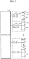
- FIG. 3 is a block diagram illustrating a configuration of a radar signal processor of a radar device according to an embodiment of the present invention. As shown in FIG. 3 , each of the n radar signal processors 110 includes a transmitting module 200 and a receiving module 300.
- the transmitting module 200 is configured to sequentially transmit radar signals through the transmitting antennas 120 connected to the i transmission channels of each of the n radar signal processors 110 and includes switches 210, a power amplifier (PA) 220, and a frequency multiplier 230.
- switches 210 switches 210, a power amplifier (PA) 220, and a frequency multiplier 230.
- PA power amplifier
- the switches 210 sequentially switch to select the transmitting antennas 120, which transmit the radar signals, so as to transmit the radar signals through the transmitting antennas 120 connected to the i transmission channels of each of the n radar signal processors 110 according to a transmission timing signal.
- the transmission timing signal for the radar signals may be transmitted from the controller 140.
- the PA 220 amplifies a frequency signal output to the transmitting antenna 210.
- the frequency multiplier 230 outputs power of an output frequency that is n (integer) times an input frequency to the PA 220.
- the receiving module 300 is configured to collectively receive the radar signals, which are transmitted sequentially through the transmitting antennas 120 connected to the i transmission channels of each of the n radar signal processors 110, through the receiving antennas 130 connected to the j reception channels of each of the n radar signal processors 110 and includes a low noise amplifier (LNA) 310 and a mixer 320.
- LNA low noise amplifier
- the LNA 310 performs low-noise amplification on weak frequency signals which are input through the receiving antennas 130 connected to the j reception channels of each of the n radar signal processors 110.
- the mixer 320 performs a frequency shift by multiplying frequency signals output from the transmitting antennas 120 by frequency signals received by the receiving antennas 130.
- the controller 140 detects the target object and calculates a position thereof using the above-described Equations from the frequency shift results obtained by the mixer 320 of each of the n radar signal processors 110.
- the plurality of transmitting antennas 120 and the plurality of receiving antennas 130 which are provided in the radar device 100, may be arrayed to have a widely distributed surveillance region.
- the n*i transmitting antennas 120 and the n*j receiving antennas 130 are arrayed to intersect with each other in a form of a straight line according to not claimed aspects or in form of a curved line according to the claimed invention, thereby having a widely distributed surveillance region, and a distribution interval between received beams on a received beam distribution image is implemented to be less than half of a received wavelength.
- the number of the transmitting antennas 120 and the number of the receiving antennas 130, which are arrayed to intersect with each other in the form of a straight or curved line increase, a more widely distributed surveillance region is achieved.
- a grating lobe which is an undesirable radiation lobe may be reduced such that performance of the radar device may be improved.
- the grating lobe occurs when the distribution interval of the received beams on the received beam distribution image is greater than or equal to half of the received wavelength.
- n*i transmitting antennas 120 and the n*j receiving antennas 130 are arrayed to intersect with each other in the form of a straight or curved line, a distribution of the received beams on the received beam distribution image are more concentrated on a center of the received beam distribution image so as to reduce a side lobe such that the performance of the radar device may be improved.
- the side lobe is increased.
- the n*i transmitting antennas 120 may be continuously or discontinuously arrayed with respect to adjacent transmitting antennas, and the n*j receiving antennas 130 may also be continuously or discontinuously arrayed with respect to adjacent receiving antennas.
- the controller 140 controls the n radar signal processors 110 whenever the n*i transmitting antennas 120 sequentially or respectively transmit radar signals so as to allow all of the n*j receiving antennas 130 to collectively receive the radar signals.
- the n*i transmitting antennas 120 and the n*j receiving antennas 130 may be arrayed so as to allow positions of the received beams formed by the radar signals which are received by the n*j receiving antennas 130 to not overlap on the received beam distribution image.
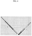
- FIG. 4 is a diagram illustrating an antenna array structure of a radar device according to a first embodiment not forming part of the claimed invention.
- FIG. 4 illustrates the first embodiment implemented such that 4*3 transmitting antennas 120 and 4*4 receiving antennas 130 are arrayed to intersect with each other at right angle in a form of straight lines which are inclined at -45 degrees/+45 degrees from the ground.
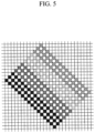
- FIG. 5 is a diagram showing a received beam distribution image obtained by the antenna array structure according to the first embodiment shown in FIG. 1 . As shown in FIG. 5 , it can be seen that a received beam distribution has an inclined rectangular shape having a size of 12*16, thereby having a widely distributed surveillance region.
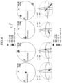
- FIG. 6 shows graphs illustrating shapes of received beams formed by the antenna array structure according to the first embodiment shown in FIG. 4 that illustrate the shapes of the received beams which are viewed from an x-axis and a z-axis by performing fast Fourier transform (FFT) on radar signals received by the receiving antennas.
- FFT fast Fourier transform
- FIG. 6 shows graphs illustrating 2D and three-dimensional (3D) received beam patterns, from a left side of FIG. 6 , when a tilt in an x-axis direction is zero degrees and a tilt in a z-axis direction is zero degrees, when the tilt in the x-axis direction is zero degrees and the tilt in the z-axis direction is 40 degrees, when the tilt in the x-axis direction is 40 degrees and the tilt in the z-axis direction is zero degrees, and when the tilt in the x-axis direction is 28 degrees and the tilt in the z-axis direction is 28 degrees.
- 3D three-dimensional
- FIG. 7 is a diagram illustrating an antenna array structure of a radar device according to a second embodiment forming part of the claimed invention.
- FIG. 7 illustrates the second embodiment implemented such that 4*3 transmitting antennas 120 and 4*4 receiving antennas 130 are arrayed to intersect with each other in a form of curved lines.
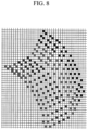
- FIG. 8 is a diagram illustrating a received beam distribution image obtained by the antenna array structure according to the second embodiment shown in FIG. 7 . As shown in FIG. 8 , it can be seen that a received beam distribution has a curved rectangular shape having a size of 12*16, thereby having a widely distributed surveillance region.
- FIG. 9 shows graphs illustrating shapes of received beams formed by the antenna array structure according to the second embodiment shown in FIG. 7 that illustrate the shapes of the received beams which are viewed from the x-axis and the z-axis by performing FFT on radar signals received by the receiving antennas.
- FIG. 9 shows graphs illustrating 2D and 3D received beam patterns, from a left side of FIG. 9 , when a tilt in an x-axis direction is zero degrees and a tilt in a z-axis direction is zero degrees, when the tilt in the x-axis direction is zero degrees and the tilt in the z-axis direction is 40 degrees, when the tilt in the x-axis direction is 40 degrees and the tilt in the z-axis direction is zero degrees, and when the tilt in the x-axis direction is 28 degrees and the tilt in the z-axis direction is 28 degrees.
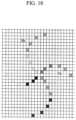
- FIG. 10 is a diagram illustrating an antenna array structure of a radar device according to a third embodiment forming part of the claimed invention.
- FIG. 10 illustrates the third embodiment implemented such that 4*3 transmitting antennas 120 and 4*4 receiving antennas 130 are arrayed to intersect with each other in a form of helical lines.
- FIG. 11 is a diagram illustrating a received beam distribution image obtained by the antenna array structure according to the third embodiment shown in FIG. 10 . As shown in FIG. 11 , it can be seen that a received beam distribution has a rectangular wave shape having a size of 12*16, thereby having a widely distributed surveillance region.
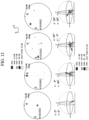
- FIG. 12 shows graphs illustrating shapes of received beams formed by the antenna array structure according to the third embodiment shown in FIG. 10 that illustrate the shapes of the received beams which are viewed from the x-axis and the z-axis by performing FFT on radar signals received by the receiving antennas.
- FIG. 12 shows graphs illustrating 2D and 3D received beam patterns, from a left side of FIG. 12 , when a tilt in an x-axis direction is zero degrees and a tilt in a z-axis direction is zero degrees, when the tilt in the x-axis direction is zero degrees and the tilt in the z-axis direction is 40 degrees, when the tilt in the x-axis direction is 40 degrees and the tilt in the z-axis direction is zero degrees, and when the tilt in the x-axis direction is 28 degrees and the tilt in the z-axis direction is 28 degrees.
- the plurality of transmitting antennas and the plurality of receiving antennas which are provided in a radar device, are arrayed to intersect with each other in the form of a curved line, thereby having a widely distributed surveillance region. Consequently, the radar device may survey a wide region. Accordingly, the radar device may be used for security and the like.
- the distribution interval between the received beams on the received beam distribution image is implemented to be less than or equal to half of the received wavelength such that a grating lobe which is an undesirable radiation lobe may be reduced. Consequently, performance of the radar device may be improved.
- a distribution of the received beams on the received beam distribution image is more concentrated on a center of the received beam distribution image, thereby reducing a side lobe. Consequently, the performance of the radar device may be improved.
- the plurality of transmitting antennas 120 and the plurality of receiving antennas 130 which are provided in the radar device 100, may be arrayed to have a concentratedly distributed surveillance region.
- n*i transmitting antennas 120 and the n*j receiving antennas 130 are arrayed on straight lines, some among the n*i transmitting antennas 120 and the n*j receiving antennas 130 are arrayed on straight lines and the remaining antennas thereamong are arrayed to be alternated.
- some positions of received beams formed by radar signals which are received by the n*j receiving antennas 130 are represented as spaces on a received beam distribution image as well as achieving a concentratedly distributed surveillance region, and a distribution interval of the received beams on the received beam distribution image is implemented to be less than half of a received wavelength.
- a grating lobe which is an undesirable radiation lobe may be reduced such that performance of the radar device may be improved.
- the grating lobe occurs when the distribution interval of the received beams on the received beam distribution image is greater than or equal to half of the received wavelength.
- the distribution of the received beams on the received beam distribution image are more concentrated on a center of the received beam distribution image to reduce the side lobe such that the performance of the radar device may be improved.
- the side lobe is decreased.
- the n*i transmitting antennas 120 may be continuously or discontinuously arrayed with respect to adjacent transmitting antennas, and the n*j receiving antennas 130 may also be continuously or discontinuously arrayed with respect to adjacent receiving antennas.
- the controller 140 controls the n radar signal processors 110 whenever the n*i transmitting antennas 120 sequentially or respectively transmit radar signals so as to allow all of the n*j receiving antennas 130 to collectively receive the radar signals.
- the n*i transmitting antennas 120 and the n*j receiving antennas 130 may be arrayed so as to allow positions of the received beams formed by the radar signals, which are received by the n*j receiving antennas 130, to not overlap on the received beam distribution image.
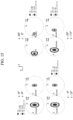
- FIG. 13 is a diagram illustrating an antenna array structure of a radar device according to a fourth embodiment not forming part of the claimed invention.
- FIG. 13 illustrates the fourth embodiment implemented such that some among 4*3 transmitting antennas 120 and 4*4 receiving antennas 130 are arrayed on straight lines and the remaining antennas thereamong are arrayed to be alternated.
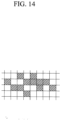
- FIG. 14 is a diagram showing a received beam distribution image obtained by the antenna array structure according to the fourth embodiment shown in FIG. 4 . As shown in FIG. 14 , it can be seen that some positions of received beams formed by radar signals, which are received by the receiving antennas, exhibit a concentrated distribution while being represented as spaces on a received beam distribution image, thereby having a concentratedly distributed surveillance region.
- FIG. 15 shows graphs illustrating shapes of received beams formed by the antenna array structure according to the fourth embodiment shown in FIG. 13 that illustrate the shapes of the received beams which are viewed from the x-axis and the z-axis by performing FFT on the radar signals received by the receiving antennas.
- Graphs on an upper left side of FIG. 15 show received beam patterns when a tilt in the x-axis direction is zero degrees and a tilt in the z-axis direction is zero degrees
- graphs on an upper right side thereof show received beam patterns when the tilt in the x-axis direction is 40 degrees and the tilt in the z-axis direction is zero degrees
- graphs on a lower left side thereof show received beam patterns when the tilt in the x-axis direction is zero degrees and the tilt in the z-axis direction is 15 degrees
- graphs on a lower right side thereof show received beam patterns when the tilt in the x-axis direction is 20 degrees and the tilt in the z-axis direction is 7.5 degrees.
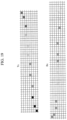
- FIG. 16 is a diagram illustrating an antenna array structure of a radar device according to a fifth embodiment not forming part of the claimed invention.
- FIG. 16 illustrates the fifth embodiment implemented such that some among 2*3 transmitting antennas 120 and 2*4 receiving antennas 130 are arrayed on straight lines and the remaining antennas thereamong are arrayed to be alternated.
- FIG. 17 is a diagram illustrating a received beam distribution image obtained by the antenna array structure according to the fifth embodiment shown in FIG. 16 . As shown in FIG. 17 , it can be seen that some positions of received beams formed by radar signals, which are received by the receiving antennas, exhibit a concentrated distribution similar to an elliptical shape while being represented as spaces on a received beam distribution image, thereby having a concentratedly distributed surveillance region.
- FIG. 18 shows graphs illustrating shapes of received beams formed by the antenna array structure according to the fifth embodiment shown in FIG. 16 that illustrate the shapes of the received beams which are viewed from an x-axis and a z-axis by performing FFT on the radar signals received by the receiving antennas.
- Graphs on an upper left side of FIG. 18 show received beam patterns when a tilt in the x-axis direction is zero degrees and a tilt in the z-axis direction is zero degrees
- graphs on an upper right side thereof show received beam patterns when the tilt in the x-axis direction is 40 degrees and the tilt in the z-axis direction is zero degrees
- graphs on a lower left side thereof show received beam patterns when the tilt in the x-axis direction is zero degrees and the tilt in the z-axis direction is 15 degrees
- graphs on a lower right side thereof show received beam patterns when the tilt in the x-axis direction is 20 degrees and the tilt in the z-axis direction is 7.5 degrees.
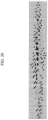
- FIG. 19 is a diagram illustrating an antenna array structure of a radar device according to a sixth embodiment not forming part of the claimed invention.
- FIG. 19 illustrates the sixth embodiment implemented such that some among 4*3 transmitting antennas 120 and 4*4 receiving antennas 130 are arrayed on straight lines and the remaining antennas thereamong are arrayed to be alternated.
- FIG. 20 is a diagram illustrating a received beam distribution image obtained by the antenna array structure according to the sixth embodiment shown in FIG. 19 . As shown in FIG. 20 , it can be seen that some positions of received beams formed by radar signals, which are received by the receiving antennas, exhibit a concentrated distribution similar to a long elliptical shape while being represented as spaces on a received beam distribution image, thereby having a concentratedly distributed surveillance region.
- FIG. 21 shows graphs illustrating shapes of received beams formed by the antenna array structure according to the sixth embodiment shown in FIG. 19 that illustrate the shapes of the received beams which are viewed from an x-axis and a z-axis by performing FFT on the radar signals received by the receiving antennas.
- Graphs on an upper left side of FIG. 21 show received beam patterns when a tilt in the x-axis direction is zero degrees and a tilt in the z-axis direction is zero degrees
- graphs on an upper right side thereof show received beam patterns when the tilt in the x-axis direction is 40 degrees and the tilt in the z-axis direction is zero degrees
- graphs on a lower left side thereof show received beam patterns when the tilt in the x-axis direction is zero degrees and the tilt in the z-axis direction is 15 degrees
- graphs on a lower right side thereof show received beam patterns when the tilt in the x-axis direction is 20 degrees and the tilt in the z-axis direction is 7.5 degrees.
- the radar device instead of all of the plurality of transmitting antennas and the plurality of receiving antennas, which are provided in the radar device, being arrayed on straight lines, some among the plurality of transmitting antennas and the plurality of receiving antennas are arrayed in the form of a straight line and the remaining antennas thereamong are arrayed to be alternated, thereby having a concentratedly distributed surveillance region. Consequently, the radar device may concentratedly survey a region of interest. Accordingly, the radar device may be used for a vehicle and the like.
- the distribution interval between the received beams on the received beam distribution image is implemented to be less than or equal to half of the received wavelength such that a grating lobe which is an undesirable radiation lobe may be reduced. Consequently, performance of the radar device may be improved.
- a distribution of the received beams on the received beam distribution image is more concentrated on a center of the received beam distribution image, thereby reducing a side lobe. Consequently, the performance of the radar device may be improved.
- a virtual antenna with high spatial resolution can be implemented to have a 2D received beam distribution using a plurality of transmitting antennas and a plurality of receiving antennas. Consequently, a radar device can be provided to have high spatial resolution using a smaller number of physical transmitting and receiving antennas.
- the plurality of transmitting antennas and the plurality of receiving antennas which are provided in the radar device, are arrayed to intersect with each other in the form of a curved line, thereby having a widely distributed surveillance region. Consequently, the radar device can survey a wide region.
- the radar device instead of all of the plurality of transmitting antennas and the plurality of receiving antennas, which are provided in the radar device, being arrayed on straight lines, some among the plurality of transmitting antennas and the plurality of receiving antennas are arrayed in the form of a straight line and the remaining antennas thereamong are arrayed to be alternated, thereby having a concentratedly distributed surveillance region. Consequently, the radar device can concentratedly survey a region of interest.
- a distribution interval between received beams on a received beam distribution image is implemented to be less than or equal to half of a received wavelength, thereby removing a grating lobe which is an undesirable radiation lobe. Consequently, performance of the radar device can be improved.
- a distributio n of the received beams on the received beam distribution image is implemented to be more concentrated on a center of the received beam distribution image, thereby reducing a side lobe. Consequently, the performance of the radar device can be improved.
- the present invention is industrially applicable in the field of radar antenna technology and application thereof.
Landscapes
- Engineering & Computer Science (AREA)
- Radar, Positioning & Navigation (AREA)
- Remote Sensing (AREA)
- Physics & Mathematics (AREA)
- Computer Networks & Wireless Communication (AREA)
- General Physics & Mathematics (AREA)
- Electromagnetism (AREA)
- Signal Processing (AREA)
- Computer Security & Cryptography (AREA)
- Radar Systems Or Details Thereof (AREA)
Claims (5)
- Dispositif radar (100) comprenant :n processeurs de signaux radar (110), chacun inclut i canaux de transmission et j canaux de réception, configurés pour transmettre des signaux radar à travers les i canaux de transmission, recevoir les signaux radar réfléchis par un objet cible à travers les j canaux de réception, et traiter les signaux radar reçus, calculant ainsi une portée par rapport à l'objet cible et des données Doppler pour chacun des j canaux de réception ;n*i antennes physiques de transmission (120) connectées aux i canaux de transmission de chacun des n processeurs de signaux radar (110) et configurées pour transmettre les signaux radar ;n*j antennes physiques de réception (130) connectées aux j canaux de réception de chacun des n processeurs de signaux radar (110) et configurées pour recevoir les signaux radar réfléchis par l'objet cible ; etun contrôleur (140) configuré pour commander les opérations des n processeurs de signaux radar (110) et générer un réseau d'antennes virtuelles ayant une distribution de faisceau bidimensionnelle (2D) en commandant les n*i antennes de transmission (120) et les n*j antennes de réception (130) en référence à des informations relatives à la configuration de l'antenne ;où n, i, j sont des nombres entiers supérieurs à un, respectivement ;dans lequel les informations relatives à la configuration de l'antenne définissent des informations sur le réseau stationnaire des n*i antennes de transmission (120) et des n*j antennes de réception (130), des informations sur la séquence de pilotage des n*i antennes de transmission (120) et des n*j antennes de réception (130), et des informations sur la distribution des faisceaux 2D sur le réseau d'antennes virtuelles dynamique selon une séquence de commande des n*i antennes de transmission (120) et des n*j antennes de réception (130) ; etcaractérisé en ce que les n*i antennes de transmission (120) sont disposées sous la forme d'une première ligne courbe et que les n*j antennes de réception (130) sont disposées sous la forme d'une deuxième ligne courbe de sorte que la première ligne courbe et la deuxième ligne courbe se croisent, ce qui permet d'obtenir une région de surveillance largement distribuée.
- Dispositif radar (100) selon la revendication 1, dans lequel le contrôleur (140) calcule une position de l'objet cible à partir des données de cartographie d'antenne virtuelle, dans lesquelles la portée de l'objet cible et les données Doppler pour chacun des canaux de réception, qui sont calculées par les n processeurs de signaux radar (110), sont réarrangées selon les informations de distribution de faisceau 2D du réseau d'antennes virtuelles en référence aux informations relatives à la configuration de l'antenne.
- Dispositif radar (100) selon la revendication 1, dans lequel :
un intervalle de distribution entre les antennes virtuelles du réseau d'antennes virtuelles est inférieur à la moitié d'une longueur d'onde reçue. - Dispositif radar (100) selon la revendication 1, dans lequel le contrôleur (140) commande les n processeurs de signaux radar (110) chaque fois que les n*i antennes de transmission (120) transmettent séquentiellement les signaux radar de manière à permettre à toutes les n*j antennes de réception (130) de recevoir collectivement les signaux radar.
- Dispositif radar (100) selon la revendication 1, dans lequel les n*i antennes de transmission (120) et les n*j antennes de réception (130) sont disposées de manière à ce que les positions des faisceaux formés par les signaux radar, qui sont reçus par les n*j antennes de réception (130), ne se chevauchent pas les unes les autres.
Applications Claiming Priority (3)
| Application Number | Priority Date | Filing Date | Title |
|---|---|---|---|
| KR1020180035462A KR102157583B1 (ko) | 2018-03-27 | 2018-03-27 | 레이더 장치 |
| KR1020180035463A KR102019171B1 (ko) | 2018-03-27 | 2018-03-27 | 레이더 장치 |
| PCT/KR2019/003543 WO2019190186A1 (fr) | 2018-03-27 | 2019-03-27 | Dispositif radar |
Publications (3)
| Publication Number | Publication Date |
|---|---|
| EP3572838A1 EP3572838A1 (fr) | 2019-11-27 |
| EP3572838A4 EP3572838A4 (fr) | 2020-04-15 |
| EP3572838B1 true EP3572838B1 (fr) | 2024-08-14 |
Family
ID=68060634
Family Applications (1)
| Application Number | Title | Priority Date | Filing Date |
|---|---|---|---|
| EP19733388.3A Active EP3572838B1 (fr) | 2018-03-27 | 2019-03-27 | Dispositif radar |
Country Status (4)
| Country | Link |
|---|---|
| US (1) | US11435435B2 (fr) |
| EP (1) | EP3572838B1 (fr) |
| CN (1) | CN110537106B (fr) |
| WO (1) | WO2019190186A1 (fr) |
Cited By (1)
| Publication number | Priority date | Publication date | Assignee | Title |
|---|---|---|---|---|
| US12405353B2 (en) * | 2022-01-26 | 2025-09-02 | Aptiv Technologies AG | Radar device |
Families Citing this family (12)
| Publication number | Priority date | Publication date | Assignee | Title |
|---|---|---|---|---|
| US11269049B2 (en) | 2019-03-18 | 2022-03-08 | Nxp Usa, Inc. | Distributed aperture automotive radar system |
| US11226397B2 (en) * | 2019-08-06 | 2022-01-18 | Waymo Llc | Slanted radomes |
| US11385325B2 (en) * | 2019-08-07 | 2022-07-12 | Waymo Llc | Corrugated radomes |
| DE102020102033A1 (de) * | 2020-01-28 | 2021-07-29 | Krohne Messtechnik Gmbh | Radar-Antennenanordnung |
| DE102020110696A1 (de) * | 2020-04-20 | 2021-10-21 | Symeo Gmbh | Radar-Verfahren und Radar-System zur phasenkohärenten Auswertung |
| EP3910365A1 (fr) * | 2020-05-14 | 2021-11-17 | Nxp B.V. | Système d'antenne et procédé de fonctionnement d'un système d'antenne |
| US11988740B2 (en) * | 2020-09-08 | 2024-05-21 | Anduril Industries, Inc. | Millimeter wavelength radar antenna for drone interception |
| US11888554B2 (en) * | 2020-09-23 | 2024-01-30 | Nxp Usa, Inc. | Automotive MIMO radar system using efficient difference co-array processor |
| US11860297B2 (en) * | 2021-03-08 | 2024-01-02 | GM Global Technology Operations LLC | High resolution unambiguous radar |
| CN114322743B (zh) * | 2022-01-05 | 2024-04-12 | 瞬联软件科技(北京)有限公司 | 一种隧道形变实时监测系统及监测方法 |
| US12189017B2 (en) * | 2022-01-27 | 2025-01-07 | Smart Radar System, Inc. | In-cabin radar apparatus |
| EP4597850A1 (fr) * | 2024-01-31 | 2025-08-06 | Turck Holding GmbH | Dispositif d'antenne bistatique |
Citations (1)
| Publication number | Priority date | Publication date | Assignee | Title |
|---|---|---|---|---|
| US20170082730A1 (en) * | 2015-09-17 | 2017-03-23 | Panasonic Corporation | Radar device |
Family Cites Families (26)
| Publication number | Priority date | Publication date | Assignee | Title |
|---|---|---|---|---|
| JP3969854B2 (ja) * | 1998-07-09 | 2007-09-05 | 三井造船株式会社 | マイクロ波を用いた二次元映像装置用アレイアンテナ |
| PT1485731E (pt) * | 2002-03-13 | 2006-08-31 | Raytheon Canada Ltd | Sistema e metodo de geracao espectral em radar |
| DE112004002165T5 (de) | 2003-11-18 | 2006-09-07 | Murata Mfg. Co., Ltd., Nagaokakyo | Radarsystem |
| US7612706B2 (en) * | 2004-07-16 | 2009-11-03 | Fujitsu Ten Limited | Monopulse radar apparatus and antenna switch |
| US7283085B2 (en) | 2005-03-24 | 2007-10-16 | Agilent Technologies, Inc. | System and method for efficient, high-resolution microwave imaging using complementary transmit and receive beam patterns |
| JP4853027B2 (ja) | 2006-01-17 | 2012-01-11 | 信越半導体株式会社 | シリコン単結晶ウエーハの製造方法 |
| JP2010071865A (ja) | 2008-09-19 | 2010-04-02 | Fujitsu Ten Ltd | 信号処理装置、及びレーダ装置。 |
| KR101325759B1 (ko) | 2009-12-16 | 2013-11-08 | 한국전자통신연구원 | 다중 입출력 레이더 장치 및 이를 이용한 무선통신 방법 |
| KR101137038B1 (ko) * | 2010-01-05 | 2012-04-19 | 주식회사 만도 | 레이더 장치, 안테나 장치 및 데이터 획득 방법 |
| DE102011113015A1 (de) | 2011-09-09 | 2013-03-14 | Astyx Gmbh | Abbildender Radarsensor mit synthetischer Vergrößerung der Antennenaperatur und zweidimensionaler Strahlschwenkung |
| DE102011113018A1 (de) | 2011-09-09 | 2013-03-14 | Astyx Gmbh | Abbildender Radarsensor mit schmaler Antennenkeule und weitem Winkel-Detektionsbereich |
| JP2013130475A (ja) | 2011-12-21 | 2013-07-04 | Mitsubishi Electric Corp | アンテナ配置算出装置 |
| KR101450333B1 (ko) * | 2013-02-07 | 2014-10-13 | 주식회사 만도 | 자동 얼라이먼트를 제공하는 방법 및 레이더 장치 |
| KR101477909B1 (ko) | 2013-06-03 | 2014-12-30 | 주식회사 만도 | 레이더 장치 및 안테나 장치 |
| KR20140144826A (ko) * | 2013-06-12 | 2014-12-22 | 주식회사 만도 | 레이더 장치 및 안테나 장치 |
| WO2015029339A1 (fr) * | 2013-08-29 | 2015-03-05 | パナソニックIpマネジメント株式会社 | Système radar et procédé de détection de cible |
| JP2015132474A (ja) | 2014-01-09 | 2015-07-23 | 株式会社村田製作所 | フェーズドアレイアンテナおよびアクティブセンサ |
| KR101736713B1 (ko) | 2014-03-20 | 2017-05-17 | 주식회사 에이스테크놀로지 | 레이더 배열 안테나 |
| US10627480B2 (en) | 2014-07-17 | 2020-04-21 | Texas Instruments Incorporated | Distributed radar signal processing in a radar system |
| JP6271032B2 (ja) * | 2014-10-30 | 2018-01-31 | 三菱電機株式会社 | アンテナ諸元推定装置及びレーダ装置 |
| US9733340B2 (en) * | 2014-11-21 | 2017-08-15 | Texas Instruments Incorporated | Techniques for high arrival angle resolution using multiple nano-radars |
| DE102014118031A1 (de) | 2014-12-05 | 2016-06-09 | Astyx Gmbh | Radarsensor, Radarsensor-System sowie Verfahren zur Bestimmung der Position eines Objekts mit horizontaler und vertikaler digitaler Strahlformung zur Vermessung von punkt- und flächenförmig reflektierenden Objekten |
| KR101553878B1 (ko) | 2015-02-06 | 2015-09-17 | 엘아이지넥스원 주식회사 | 송신 스위칭 레이더 시스템의 부엽 레벨 억제 방법 |
| KR101777015B1 (ko) * | 2015-10-23 | 2017-09-11 | 재단법인대구경북과학기술원 | 회전을 이용하여 가상 l형 안테나를 생성하는 안테나 장치 |
| EP3171453B1 (fr) * | 2015-11-17 | 2019-02-13 | VEGA Grieshaber KG | Dispositif d'antenne et procédé de fonctionnement d'un dispositif d'antenne |
| CN105932427B (zh) * | 2016-05-04 | 2018-10-09 | 西安电子工程研究所 | 一种毫米波成像雷达一维阵列天线及时序控制方法 |
-
2019
- 2019-03-27 EP EP19733388.3A patent/EP3572838B1/fr active Active
- 2019-03-27 CN CN201980001158.1A patent/CN110537106B/zh active Active
- 2019-03-27 WO PCT/KR2019/003543 patent/WO2019190186A1/fr not_active Ceased
- 2019-03-27 US US16/477,190 patent/US11435435B2/en active Active
Patent Citations (1)
| Publication number | Priority date | Publication date | Assignee | Title |
|---|---|---|---|---|
| US20170082730A1 (en) * | 2015-09-17 | 2017-03-23 | Panasonic Corporation | Radar device |
Non-Patent Citations (1)
| Title |
|---|
| BAHRAMIABARGHOUEI HADI ET AL: "Flexible 16 Antenna Array for Microwave Breast Cancer Detection", IEEE TRANSACTIONS ON BIOMEDICAL ENGINEERING, IEEE, USA, vol. 62, no. 10, 1 October 2015 (2015-10-01), pages 2516 - 2525, XP011668916, ISSN: 0018-9294, [retrieved on 20150916], DOI: 10.1109/TBME.2015.2434956 * |
Cited By (1)
| Publication number | Priority date | Publication date | Assignee | Title |
|---|---|---|---|---|
| US12405353B2 (en) * | 2022-01-26 | 2025-09-02 | Aptiv Technologies AG | Radar device |
Also Published As
| Publication number | Publication date |
|---|---|
| US20200333432A1 (en) | 2020-10-22 |
| CN110537106A (zh) | 2019-12-03 |
| US11435435B2 (en) | 2022-09-06 |
| EP3572838A1 (fr) | 2019-11-27 |
| EP3572838A4 (fr) | 2020-04-15 |
| CN110537106B (zh) | 2023-03-28 |
| WO2019190186A1 (fr) | 2019-10-03 |
Similar Documents
| Publication | Publication Date | Title |
|---|---|---|
| EP3572838B1 (fr) | Dispositif radar | |
| US11422254B2 (en) | Radar sensor apparatus for vehicle, object detecting method, and antenna apparatus therefor | |
| US10852407B2 (en) | Imaging radar sensor with narrow antenna lobe and wide angle-detection range | |
| JP6570610B2 (ja) | レーダ装置 | |
| US20220075023A1 (en) | Radar device | |
| KR102735493B1 (ko) | 레이더 장치와 물체 감지 방법 및 그를 위한 신호 처리 장치 | |
| US10816641B2 (en) | Imaging radar sensor with synthetic enlargement of the antenna aperture and two-dimensional beam sweep | |
| CN111630405B (zh) | 雷达装置 | |
| US11579283B2 (en) | Imaging radar system having a random receiving array for determining the angle of objects in two dimensions by means of a spread arrangement of the receiving antennas in one dimension | |
| US9140787B2 (en) | Radar sensor for motor vehicles, especially LCA sensor | |
| EP3961242A1 (fr) | Radar multimode avec résolution d'ambiguïté spatiale | |
| WO2022229386A1 (fr) | Radar mimo utilisant une antenne à balayage de fréquence | |
| KR102157583B1 (ko) | 레이더 장치 | |
| JP2013152201A (ja) | レーダ装置 | |
| JP7374333B2 (ja) | レーダ装置 | |
| US11150338B2 (en) | Azimuth calculation device and azimuth calculation method | |
| WO2023218632A1 (fr) | Dispositif radar et procédé de détection cible | |
| JP3780904B2 (ja) | レーダ装置 | |
| KR102019171B1 (ko) | 레이더 장치 | |
| EP3742196B1 (fr) | Dispositif radar | |
| KR102812952B1 (ko) | 차량용 레이더 장치 및 제어방법 | |
| Ogawa et al. | Development of Automotive Millimeter Wave Radars | |
| CN118091639A (zh) | 基于毫米波雷达系统的目标三维识别方法及装置 | |
| JP2006349568A (ja) | エイミング誤差推定装置 |
Legal Events
| Date | Code | Title | Description |
|---|---|---|---|
| STAA | Information on the status of an ep patent application or granted ep patent |
Free format text: STATUS: UNKNOWN |
|
| STAA | Information on the status of an ep patent application or granted ep patent |
Free format text: STATUS: THE INTERNATIONAL PUBLICATION HAS BEEN MADE |
|
| PUAI | Public reference made under article 153(3) epc to a published international application that has entered the european phase |
Free format text: ORIGINAL CODE: 0009012 |
|
| STAA | Information on the status of an ep patent application or granted ep patent |
Free format text: STATUS: REQUEST FOR EXAMINATION WAS MADE |
|
| 17P | Request for examination filed |
Effective date: 20190704 |
|
| AK | Designated contracting states |
Kind code of ref document: A1 Designated state(s): AL AT BE BG CH CY CZ DE DK EE ES FI FR GB GR HR HU IE IS IT LI LT LU LV MC MK MT NL NO PL PT RO RS SE SI SK SM TR |
|
| AX | Request for extension of the european patent |
Extension state: BA ME |
|
| STAA | Information on the status of an ep patent application or granted ep patent |
Free format text: STATUS: EXAMINATION IS IN PROGRESS |
|
| A4 | Supplementary search report drawn up and despatched |
Effective date: 20200312 |
|
| RIC1 | Information provided on ipc code assigned before grant |
Ipc: G01S 13/44 20060101ALI20200306BHEP Ipc: G01S 13/58 20060101ALI20200306BHEP Ipc: H01Q 1/32 20060101ALI20200306BHEP Ipc: H01Q 21/28 20060101ALI20200306BHEP Ipc: G01S 13/34 20060101ALI20200306BHEP Ipc: G01S 13/02 20060101AFI20200306BHEP Ipc: G01S 13/88 20060101ALI20200306BHEP Ipc: G01S 7/03 20060101ALI20200306BHEP Ipc: G01S 13/931 20200101ALI20200306BHEP Ipc: H01Q 21/06 20060101ALI20200306BHEP |
|
| 17Q | First examination report despatched |
Effective date: 20200325 |
|
| DAV | Request for validation of the european patent (deleted) | ||
| DAX | Request for extension of the european patent (deleted) | ||
| REG | Reference to a national code |
Ref country code: DE Ref legal event code: R079 Free format text: PREVIOUS MAIN CLASS: G01S0013020000 Ipc: G01S0013340000 Ref country code: DE Ref legal event code: R079 Ref document number: 602019056983 Country of ref document: DE Free format text: PREVIOUS MAIN CLASS: G01S0013020000 Ipc: G01S0013340000 |
|
| GRAP | Despatch of communication of intention to grant a patent |
Free format text: ORIGINAL CODE: EPIDOSNIGR1 |
|
| STAA | Information on the status of an ep patent application or granted ep patent |
Free format text: STATUS: GRANT OF PATENT IS INTENDED |
|
| RIC1 | Information provided on ipc code assigned before grant |
Ipc: H01Q 25/00 20060101ALI20240228BHEP Ipc: H01Q 1/32 20060101ALI20240228BHEP Ipc: H01Q 21/28 20060101ALI20240228BHEP Ipc: H01Q 21/06 20060101ALI20240228BHEP Ipc: G01S 13/931 20200101ALI20240228BHEP Ipc: G01S 13/58 20060101ALI20240228BHEP Ipc: G01S 13/44 20060101ALI20240228BHEP Ipc: G01S 13/34 20060101AFI20240228BHEP |
|
| INTG | Intention to grant announced |
Effective date: 20240314 |
|
| GRAS | Grant fee paid |
Free format text: ORIGINAL CODE: EPIDOSNIGR3 |
|
| GRAA | (expected) grant |
Free format text: ORIGINAL CODE: 0009210 |
|
| STAA | Information on the status of an ep patent application or granted ep patent |
Free format text: STATUS: THE PATENT HAS BEEN GRANTED |
|
| AK | Designated contracting states |
Kind code of ref document: B1 Designated state(s): AL AT BE BG CH CY CZ DE DK EE ES FI FR GB GR HR HU IE IS IT LI LT LU LV MC MK MT NL NO PL PT RO RS SE SI SK SM TR |
|
| REG | Reference to a national code |
Ref country code: GB Ref legal event code: FG4D |
|
| REG | Reference to a national code |
Ref country code: CH Ref legal event code: EP |
|
| REG | Reference to a national code |
Ref country code: DE Ref legal event code: R096 Ref document number: 602019056983 Country of ref document: DE |
|
| REG | Reference to a national code |
Ref country code: IE Ref legal event code: FG4D |
|
| REG | Reference to a national code |
Ref country code: LT Ref legal event code: MG9D |
|
| REG | Reference to a national code |
Ref country code: NL Ref legal event code: MP Effective date: 20240814 |
|
| PG25 | Lapsed in a contracting state [announced via postgrant information from national office to epo] |
Ref country code: NO Free format text: LAPSE BECAUSE OF FAILURE TO SUBMIT A TRANSLATION OF THE DESCRIPTION OR TO PAY THE FEE WITHIN THE PRESCRIBED TIME-LIMIT Effective date: 20241114 |
|
| REG | Reference to a national code |
Ref country code: AT Ref legal event code: MK05 Ref document number: 1713795 Country of ref document: AT Kind code of ref document: T Effective date: 20240814 |
|
| PG25 | Lapsed in a contracting state [announced via postgrant information from national office to epo] |
Ref country code: PT Free format text: LAPSE BECAUSE OF FAILURE TO SUBMIT A TRANSLATION OF THE DESCRIPTION OR TO PAY THE FEE WITHIN THE PRESCRIBED TIME-LIMIT Effective date: 20241216 Ref country code: NL Free format text: LAPSE BECAUSE OF FAILURE TO SUBMIT A TRANSLATION OF THE DESCRIPTION OR TO PAY THE FEE WITHIN THE PRESCRIBED TIME-LIMIT Effective date: 20240814 Ref country code: FI Free format text: LAPSE BECAUSE OF FAILURE TO SUBMIT A TRANSLATION OF THE DESCRIPTION OR TO PAY THE FEE WITHIN THE PRESCRIBED TIME-LIMIT Effective date: 20240814 Ref country code: GR Free format text: LAPSE BECAUSE OF FAILURE TO SUBMIT A TRANSLATION OF THE DESCRIPTION OR TO PAY THE FEE WITHIN THE PRESCRIBED TIME-LIMIT Effective date: 20241115 Ref country code: PL Free format text: LAPSE BECAUSE OF FAILURE TO SUBMIT A TRANSLATION OF THE DESCRIPTION OR TO PAY THE FEE WITHIN THE PRESCRIBED TIME-LIMIT Effective date: 20240814 |
|
| PG25 | Lapsed in a contracting state [announced via postgrant information from national office to epo] |
Ref country code: BG Free format text: LAPSE BECAUSE OF FAILURE TO SUBMIT A TRANSLATION OF THE DESCRIPTION OR TO PAY THE FEE WITHIN THE PRESCRIBED TIME-LIMIT Effective date: 20240814 |
|
| PG25 | Lapsed in a contracting state [announced via postgrant information from national office to epo] |
Ref country code: LV Free format text: LAPSE BECAUSE OF FAILURE TO SUBMIT A TRANSLATION OF THE DESCRIPTION OR TO PAY THE FEE WITHIN THE PRESCRIBED TIME-LIMIT Effective date: 20240814 |
|
| PG25 | Lapsed in a contracting state [announced via postgrant information from national office to epo] |
Ref country code: AT Free format text: LAPSE BECAUSE OF FAILURE TO SUBMIT A TRANSLATION OF THE DESCRIPTION OR TO PAY THE FEE WITHIN THE PRESCRIBED TIME-LIMIT Effective date: 20240814 Ref country code: IS Free format text: LAPSE BECAUSE OF FAILURE TO SUBMIT A TRANSLATION OF THE DESCRIPTION OR TO PAY THE FEE WITHIN THE PRESCRIBED TIME-LIMIT Effective date: 20241214 |
|
| PG25 | Lapsed in a contracting state [announced via postgrant information from national office to epo] |
Ref country code: HR Free format text: LAPSE BECAUSE OF FAILURE TO SUBMIT A TRANSLATION OF THE DESCRIPTION OR TO PAY THE FEE WITHIN THE PRESCRIBED TIME-LIMIT Effective date: 20240814 |
|
| PG25 | Lapsed in a contracting state [announced via postgrant information from national office to epo] |
Ref country code: ES Free format text: LAPSE BECAUSE OF FAILURE TO SUBMIT A TRANSLATION OF THE DESCRIPTION OR TO PAY THE FEE WITHIN THE PRESCRIBED TIME-LIMIT Effective date: 20240814 Ref country code: RS Free format text: LAPSE BECAUSE OF FAILURE TO SUBMIT A TRANSLATION OF THE DESCRIPTION OR TO PAY THE FEE WITHIN THE PRESCRIBED TIME-LIMIT Effective date: 20241114 |
|
| PG25 | Lapsed in a contracting state [announced via postgrant information from national office to epo] |
Ref country code: RS Free format text: LAPSE BECAUSE OF FAILURE TO SUBMIT A TRANSLATION OF THE DESCRIPTION OR TO PAY THE FEE WITHIN THE PRESCRIBED TIME-LIMIT Effective date: 20241114 Ref country code: PT Free format text: LAPSE BECAUSE OF FAILURE TO SUBMIT A TRANSLATION OF THE DESCRIPTION OR TO PAY THE FEE WITHIN THE PRESCRIBED TIME-LIMIT Effective date: 20241216 Ref country code: PL Free format text: LAPSE BECAUSE OF FAILURE TO SUBMIT A TRANSLATION OF THE DESCRIPTION OR TO PAY THE FEE WITHIN THE PRESCRIBED TIME-LIMIT Effective date: 20240814 Ref country code: NO Free format text: LAPSE BECAUSE OF FAILURE TO SUBMIT A TRANSLATION OF THE DESCRIPTION OR TO PAY THE FEE WITHIN THE PRESCRIBED TIME-LIMIT Effective date: 20241114 Ref country code: NL Free format text: LAPSE BECAUSE OF FAILURE TO SUBMIT A TRANSLATION OF THE DESCRIPTION OR TO PAY THE FEE WITHIN THE PRESCRIBED TIME-LIMIT Effective date: 20240814 Ref country code: LV Free format text: LAPSE BECAUSE OF FAILURE TO SUBMIT A TRANSLATION OF THE DESCRIPTION OR TO PAY THE FEE WITHIN THE PRESCRIBED TIME-LIMIT Effective date: 20240814 Ref country code: IS Free format text: LAPSE BECAUSE OF FAILURE TO SUBMIT A TRANSLATION OF THE DESCRIPTION OR TO PAY THE FEE WITHIN THE PRESCRIBED TIME-LIMIT Effective date: 20241214 Ref country code: HR Free format text: LAPSE BECAUSE OF FAILURE TO SUBMIT A TRANSLATION OF THE DESCRIPTION OR TO PAY THE FEE WITHIN THE PRESCRIBED TIME-LIMIT Effective date: 20240814 Ref country code: GR Free format text: LAPSE BECAUSE OF FAILURE TO SUBMIT A TRANSLATION OF THE DESCRIPTION OR TO PAY THE FEE WITHIN THE PRESCRIBED TIME-LIMIT Effective date: 20241115 Ref country code: FI Free format text: LAPSE BECAUSE OF FAILURE TO SUBMIT A TRANSLATION OF THE DESCRIPTION OR TO PAY THE FEE WITHIN THE PRESCRIBED TIME-LIMIT Effective date: 20240814 Ref country code: ES Free format text: LAPSE BECAUSE OF FAILURE TO SUBMIT A TRANSLATION OF THE DESCRIPTION OR TO PAY THE FEE WITHIN THE PRESCRIBED TIME-LIMIT Effective date: 20240814 Ref country code: BG Free format text: LAPSE BECAUSE OF FAILURE TO SUBMIT A TRANSLATION OF THE DESCRIPTION OR TO PAY THE FEE WITHIN THE PRESCRIBED TIME-LIMIT Effective date: 20240814 Ref country code: AT Free format text: LAPSE BECAUSE OF FAILURE TO SUBMIT A TRANSLATION OF THE DESCRIPTION OR TO PAY THE FEE WITHIN THE PRESCRIBED TIME-LIMIT Effective date: 20240814 |
|
| PG25 | Lapsed in a contracting state [announced via postgrant information from national office to epo] |
Ref country code: DK Free format text: LAPSE BECAUSE OF FAILURE TO SUBMIT A TRANSLATION OF THE DESCRIPTION OR TO PAY THE FEE WITHIN THE PRESCRIBED TIME-LIMIT Effective date: 20240814 Ref country code: RO Free format text: LAPSE BECAUSE OF FAILURE TO SUBMIT A TRANSLATION OF THE DESCRIPTION OR TO PAY THE FEE WITHIN THE PRESCRIBED TIME-LIMIT Effective date: 20240814 Ref country code: SM Free format text: LAPSE BECAUSE OF FAILURE TO SUBMIT A TRANSLATION OF THE DESCRIPTION OR TO PAY THE FEE WITHIN THE PRESCRIBED TIME-LIMIT Effective date: 20240814 |
|
| PG25 | Lapsed in a contracting state [announced via postgrant information from national office to epo] |
Ref country code: EE Free format text: LAPSE BECAUSE OF FAILURE TO SUBMIT A TRANSLATION OF THE DESCRIPTION OR TO PAY THE FEE WITHIN THE PRESCRIBED TIME-LIMIT Effective date: 20240814 |
|
| PG25 | Lapsed in a contracting state [announced via postgrant information from national office to epo] |
Ref country code: CZ Free format text: LAPSE BECAUSE OF FAILURE TO SUBMIT A TRANSLATION OF THE DESCRIPTION OR TO PAY THE FEE WITHIN THE PRESCRIBED TIME-LIMIT Effective date: 20240814 |
|
| PG25 | Lapsed in a contracting state [announced via postgrant information from national office to epo] |
Ref country code: SK Free format text: LAPSE BECAUSE OF FAILURE TO SUBMIT A TRANSLATION OF THE DESCRIPTION OR TO PAY THE FEE WITHIN THE PRESCRIBED TIME-LIMIT Effective date: 20240814 |
|
| REG | Reference to a national code |
Ref country code: DE Ref legal event code: R097 Ref document number: 602019056983 Country of ref document: DE |
|
| PLBE | No opposition filed within time limit |
Free format text: ORIGINAL CODE: 0009261 |
|
| STAA | Information on the status of an ep patent application or granted ep patent |
Free format text: STATUS: NO OPPOSITION FILED WITHIN TIME LIMIT |
|
| PGFP | Annual fee paid to national office [announced via postgrant information from national office to epo] |
Ref country code: IT Payment date: 20250327 Year of fee payment: 7 |
|
| 26N | No opposition filed |
Effective date: 20250515 |
|
| PG25 | Lapsed in a contracting state [announced via postgrant information from national office to epo] |
Ref country code: SE Free format text: LAPSE BECAUSE OF FAILURE TO SUBMIT A TRANSLATION OF THE DESCRIPTION OR TO PAY THE FEE WITHIN THE PRESCRIBED TIME-LIMIT Effective date: 20240814 |
|
| PG25 | Lapsed in a contracting state [announced via postgrant information from national office to epo] |
Ref country code: MC Free format text: LAPSE BECAUSE OF FAILURE TO SUBMIT A TRANSLATION OF THE DESCRIPTION OR TO PAY THE FEE WITHIN THE PRESCRIBED TIME-LIMIT Effective date: 20240814 |
|
| REG | Reference to a national code |
Ref country code: CH Ref legal event code: H13 Free format text: ST27 STATUS EVENT CODE: U-0-0-H10-H13 (AS PROVIDED BY THE NATIONAL OFFICE) Effective date: 20251024 |
|
| PG25 | Lapsed in a contracting state [announced via postgrant information from national office to epo] |
Ref country code: LU Free format text: LAPSE BECAUSE OF NON-PAYMENT OF DUE FEES Effective date: 20250327 |
|
| REG | Reference to a national code |
Ref country code: BE Ref legal event code: MM Effective date: 20250331 |
|
| PG25 | Lapsed in a contracting state [announced via postgrant information from national office to epo] |
Ref country code: BE Free format text: LAPSE BECAUSE OF NON-PAYMENT OF DUE FEES Effective date: 20250331 |
|
| PG25 | Lapsed in a contracting state [announced via postgrant information from national office to epo] |
Ref country code: CH Free format text: LAPSE BECAUSE OF NON-PAYMENT OF DUE FEES Effective date: 20250331 |
|
| PG25 | Lapsed in a contracting state [announced via postgrant information from national office to epo] |
Ref country code: IE Free format text: LAPSE BECAUSE OF NON-PAYMENT OF DUE FEES Effective date: 20250327 |
|
| PGFP | Annual fee paid to national office [announced via postgrant information from national office to epo] |
Ref country code: GB Payment date: 20260330 Year of fee payment: 8 |
|
| PGFP | Annual fee paid to national office [announced via postgrant information from national office to epo] |
Ref country code: DE Payment date: 20260326 Year of fee payment: 8 |
|
| PGFP | Annual fee paid to national office [announced via postgrant information from national office to epo] |
Ref country code: FR Payment date: 20260330 Year of fee payment: 8 |