EP3573023B1 - Procédé de détermination des informations spatiales d'une structure gazeuse - Google Patents
Procédé de détermination des informations spatiales d'une structure gazeuse Download PDFInfo
- Publication number
- EP3573023B1 EP3573023B1 EP19164316.2A EP19164316A EP3573023B1 EP 3573023 B1 EP3573023 B1 EP 3573023B1 EP 19164316 A EP19164316 A EP 19164316A EP 3573023 B1 EP3573023 B1 EP 3573023B1
- Authority
- EP
- European Patent Office
- Prior art keywords
- gaseous structure
- recording
- gaseous
- camera
- recorded
- Prior art date
- Legal status (The legal status is an assumption and is not a legal conclusion. Google has not performed a legal analysis and makes no representation as to the accuracy of the status listed.)
- Active
Links
Images

Classifications
-
- G—PHYSICS
- G06—COMPUTING OR CALCULATING; COUNTING
- G06T—IMAGE DATA PROCESSING OR GENERATION, IN GENERAL
- G06T7/00—Image analysis
- G06T7/50—Depth or shape recovery
- G06T7/55—Depth or shape recovery from multiple images
- G06T7/593—Depth or shape recovery from multiple images from stereo images
-
- G—PHYSICS
- G01—MEASURING; TESTING
- G01P—MEASURING LINEAR OR ANGULAR SPEED, ACCELERATION, DECELERATION, OR SHOCK; INDICATING PRESENCE, ABSENCE, OR DIRECTION, OF MOVEMENT
- G01P5/00—Measuring speed of fluids, e.g. of air stream; Measuring speed of bodies relative to fluids, e.g. of ship, of aircraft
- G01P5/001—Full-field flow measurement, e.g. determining flow velocity and direction in a whole region at the same time, flow visualisation
-
- G—PHYSICS
- G06—COMPUTING OR CALCULATING; COUNTING
- G06T—IMAGE DATA PROCESSING OR GENERATION, IN GENERAL
- G06T7/00—Image analysis
- G06T7/20—Analysis of motion
- G06T7/285—Analysis of motion using a sequence of stereo image pairs
Definitions
- the invention relates to a method for determining spatial information of a gaseous structure and a device for this, the gaseous structure being formed in particular by a gas cloud, and the method being carried out with at least one provided camera.
- the US 2013/0235163 A1 a stereo system based on two infrared cameras to derive depth information about mainly opaque objects.
- the contours of the recorded objects are extracted with the aid of an edge detection method. It is assumed that the recorded objects have a sufficient temperature contrast to the background.
- a local stereo matching method is then used to determine the spatial information of the opaque objects on the basis of the contours.
- the derivation of spatial information about semitransparent dynamic objects and structures such as moving gas and the like is not disclosed in this method.
- the disadvantage arises that a previously known background must exist for gas detection, which is not fundamentally the case under real conditions and suddenly occurring gas escapes.
- the object of the invention is to improve the determination of gaseous structures with regard to their spatial information with size and distance information and in particular additionally with movement information.
- the device required to carry out the method should be simple and easy to use. In particular, it is desirable to be able to carry out the method independently of a background of the gaseous structure.
- the method according to the invention for determining spatial information comprising movement information of a gaseous structure comprises at least the following steps: providing a first camera for recording the gaseous structure from a first recording axis and a second camera for recording the gaseous structure from a second recording axis or, alternatively, providing a single one Camera with a beam splitter, via which the gaseous structure is recorded from the first recording axis and the second recording axis; Acquiring a first recorded image from the direction of the first recorded axis and a second recorded image from the direction of the second recorded axis; Pre-filtering of the recorded images, with at least one image noise and / or further interference effects from the recorded images being reduced; Deriving features about the gaseous structure from the recorded images by means of a) difference images comprising pixel-by-pixel changes in concentration in the gaseous structure and b) images of the magnitude of the optical flow comprising spatial shifts in concentration in the gaseous structure; Merging and determining the correspondences of the derived features by
- the derivation of spatial information about gaseous structures from the image pairs supplied is based on the geometric relationship between the measurement object and the measurement system, the so-called epipolar geometry, and the assumption that similar gas structures can be seen in both images.
- Gaseous structures, gases or gas clouds in the context of the present invention include gases in the actual sense as well as gases in which contain particles, aerosols and the like, including smoke and steam.
- the gas cloud is recorded by the cameras, it stands out from the background if its temperature deviates from the temperature of the background. The greater the temperature difference and the greater the gas concentration, the more it stands out. If the gas cloud then appears in both recording images, the position of the location of the mean gas concentration in the measurement path within the gas cloud can be determined if the corresponding projections of the location in the two recording images are correspondingly similar. This property is also known as photo consistency and applies to most opaque objects in the visual realm.
- the noise and other interfering effects, in particular so-called jitter, in the recorded images are reduced with pre-filtering.
- the changes in concentration over time in the gas cloud with differential images and the spatial concentration shifts in the gas cloud with the amount of optical flow per image unit or per pixel are derived below. This characteristic information then allows one Differentiation of the gas cloud from the background without determining the background itself beforehand, and it makes it easier to find correspondences in the stereo images. Consequently, the procedure can also be used with an unknown background.
- the data obtained are then merged in a so-called global target function over all pixels of the image by weighted addition, which is described with the merging and the determination of the correspondences of the derived features by means of the correspondence determination.
- This matching is done by minimizing the objective function.
- the result is an allocation of corresponding pixels from each image pair in the form of a so-called disparity image.
- this disparity image and the calibration parameters obtained by a geometric calibration spatial information about the gas cloud that is located within the gas cloud is derived.
- the distance to the gas cloud and the direction of movement of the gas cloud can be determined from the spatial information. Since the spatial information is regenerated for each new pair of images from the camera, i.e. pixel by pixel, the position and shape of the gas cloud as well as its change over time can be tracked. This means that statements about the height and width of the cloud can be made from the measuring direction of the measuring system.
- the method according to the invention can be used for different gases and gas mixtures as well as different camera technologies or wavelength ranges, since the method is based on intrinsic properties of turbulent gas flows. This includes, for example, the medium and long-wave range of the infrared spectrum, in the environmentally relevant and sometimes toxic Absorb gases such as CH4, CO2, NH3 or SF6 infrared radiation. Furthermore, the proposed measuring system can be used indoors and outdoors and also under uncontrolled measuring conditions, since the method presented suppresses the influence of the gas background and can thus also function in the event of extreme interference.
- the real-time position of the gaseous structure relative to the at least one camera is advantageously determined. This determination takes place by means of difference images and by means of optical flow images and the features derived therefrom about the gaseous structure from the recorded images, specifically without considering the background of the gaseous structure.
- the merging and determination of the correspondences of the derived features is performed numerically with a computer system in particular by means of the global target function between the recorded images for all pixels of the recorded images.
- the method is consequently divided into two steps, namely on the one hand providing and setting up the at least one camera and on the other hand providing the computer system for the steps of capturing the recorded images, pre-filtering, deriving features, merging and determining the correspondences and to perform the derived features and finally the derivation of the spatial information including the movement information.
- the correspondence determination preferably on the basis of the global target function, is determined with a further advantage from a sum of a created cost function and a defined regularization function, depending on an assignment of corresponding pixels from the recorded images.
- the cost function is formed on the assumption that similar characteristics, i.e. H. Temporal changes in concentration and spatial shifts in concentration can be found pixel by pixel between the associated stereo images. For this purpose, the concentration changes and concentration shifts per stereo image are added, weighted pixel by pixel, and compared with one another in the cost function. A very small difference between the features from the stereo image pair corresponds to a very high level of similarity.
- the regularization function is chosen so that the disparity image resulting after minimizing the objective function has a smooth profile.
- the invention is further directed to a device for determining spatial information comprising movement information of a gaseous structure, in particular a gas cloud, having a first camera for recording the gaseous structure from a first recording axis and having a second camera for recording the gaseous structure from a second recording axis or alternatively having a single camera with a beam splitter, via which the gaseous structure from the first recording axis and the second recording axis can be recorded, the device also having a computer system which is connected to the at least one camera and on which the above-described method is used is executable.
- the device is set up and operated in particular in the manner of epipolar geometry, since the distance between the two cameras is known, and thus the angle and the distance between the two recording axes for capturing the recording images are also known. over This epipolar geometry can consequently determine the distance to the measured gas cloud.
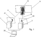
- Figure 1 shows a schematic representation of a gaseous structure 10 against a background 11, and a first camera 1 and a second camera 2, which are connected to a computer system 20, are provided for determining spatial information including the determination of movement information.
- a first recording image A1 can be recorded with the first camera 1 in a first recording axis A and a second recording image B1 can be recorded with the second camera 2 in a second recording axis B.
- the specified distance between the two cameras 1 and 2 is known.
- the method according to the invention can be carried out with the device shown in order to analyze the gaseous structure 10, in particular to include spatial information To gain movement information about the gaseous structure 10.
- the method provided according to the invention for this purpose has several method steps, which are schematized in the following Figure 2 are shown.
- FIG Figure 2 shows a process sequence of the method according to the invention starting with a provision 50 of a first camera 1 for recording the gaseous structure 10 from a first recording axis A and a second camera 2 for recording the gaseous structure 10 from a second recording axis B, as in FIG Figure 1 shown.
- the cameras 1, 2 can be provided 50 with gas cameras operating in the infrared range; it is also conceivable that hyperspectral cameras are used for gases, but these are more expensive than gas cameras. Visual cameras can be used for smoke and steam.
- the further method steps are carried out by means of the computer system 20. These begin with the acquisition 100 of a first recording image A1 from the direction of the first recording axis A and a second recording image B1 from the direction of the second recording axis B.
- the method step of pre-filtering 101 of the recorded images A1, B1 then takes place, with at least one image noise and / or further interference effects, in particular so-called jitter, from the recorded images A1, B1 being reduced in the pre-filtering 101.
- the next method step relates to the derivation of features 102 via the gaseous structure 10 from the recorded images A1, B1, specifically by means of a) difference images comprising temporal changes in concentration in the gaseous structure 10 and b) images of the amount of the optical flow comprising spatial shifts in concentration in the gaseous structure Structure 10.
- Difference images are obtained by forming the difference per pixel between two consecutive images. This highlights dynamic structures or changes in concentration within the gas cloud in the image, and constant structures, e.g. B. rigid objects in the background, suppressed.
- the optical flow is derived by finding correspondences between two consecutive images, with each pixel and its surroundings being considered when determining the correspondence. Spatial shifts in concentration in the image are thus determined pixel by pixel. The amount of optical flow per pixel is then calculated and used further.
- the next method step concerns the merging and determination 103 of the correspondences of the derived features by means of a global one Objective function and generation of a disparity image, and finally, in a last method step 104, the spatial information is derived including the movement information about the gaseous structure 10 on the basis of the disparity image.
- the objective function depends on the disparity or the assignment of corresponding pixels in the stereo image pair and is minimized on the assumption that similar temporal changes in concentration and spatial shifts in concentration exist in the stereo image pair.
- a disparity image results that represents the optimal assignment of corresponding pixels in the stereo image pair.
- spatial information about the gas cloud in the room is determined in relation to the measuring system.
Landscapes
- Engineering & Computer Science (AREA)
- Physics & Mathematics (AREA)
- General Physics & Mathematics (AREA)
- Computer Vision & Pattern Recognition (AREA)
- Theoretical Computer Science (AREA)
- Multimedia (AREA)
- Aviation & Aerospace Engineering (AREA)
- Investigating Or Analysing Materials By Optical Means (AREA)
- Length Measuring Devices By Optical Means (AREA)
Claims (9)
- Procédé de détermination d'informations spatiales d'une structure gazeuse (10), en particulier d'un nuage de gaz, le procédé comprenant au moins les étapes suivantes :- fournir (50) une première caméra (1) pour enregistrer la structure gazeuse (10) à partir d'un premier axe d'enregistrement (A) et une deuxième caméra (2) pour enregistrer la structure gazeuse (10) à partir d'un deuxième axe d'enregistrement (B), ou fournir une seule caméra avec un séparateur de faisceau par lequel la structure gazeuse (10) est enregistrée à partir du premier axe d'enregistrement (A) et du deuxième axe d'enregistrement (B),- acquérir (100) une première image enregistrée (A1) dans la direction du premier axe d'enregistrement (A) et une deuxième image enregistrée (B1) dans la direction du deuxième axe d'enregistrement (B),- dériver des caractéristiques (102) de la structure gazeuse (10) à partir des images enregistrées (A1, B1) au moyena) d'images différentielles comprenant des changements de concentration temporels dans la structure gazeuse (10) etb) des images basées sur le flux optique comprenant des décalages de concentration spatiale dans la structure gazeuse (10),- fusionner et déterminer (103) les correspondances des caractéristiques dérivées en utilisant une détermination de correspondance et générer une image de disparité et- dériver une information de mouvement sur la structure gazeuse (10) de l'information spatiale (104) au moyen de l'image de disparité.
- Procédé selon la revendication 1,
caractérisé en ce qu'
en dérivant l'information spatiale comprenant l'information de mouvement concernant la structure gazeuse (10), l'on détermine la position en temps réel de la structure gazeuse (10) par rapport à l'au moins une caméra (1, 2). - Procédé selon la revendication 1 ou 2,
caractérisé en ce que
les caractéristiques concernant la structure gazeuse (10) dérivées au moyen d'images de différence et d'images basées sur le flux optique sont détectées et évaluées à partir des images enregistrées (A1, B1) sans observation d'un arrière-plan (11) de la structure gazeuse (10). - Procédé selon l'une des revendications 1 à 3,
caractérisé en ce que
la fusion et la détermination des correspondances des caractéristiques dérivées au moyen de la détermination des correspondances et/ou d'une fonction objectif locale ou globale entre les images enregistrées (A1, B1) pour tous les pixels des images enregistrées (A1, B1) sont effectuées numériquement avec un système informatique (20). - Procédé selon l'une des revendications précédentes,
caractérisé en ce que
la fonction d'objectif globale est déterminée à partir d'une somme d'une fonction de coût générée et d'une fonction de régularisation définie, en fonction d'une affectation de pixels correspondants provenant des images enregistrées (A1, BI). - Procédé selon l'une des revendications précédentes,
caractérisé en ce que
les deux caméras (1, 2) sont alignées entre elles et par rapport à la structure gazeuse (10) pour effectuer une mesure de géométrie épipolaire. - Procédé selon l'une des revendications précédentes,
caractérisé en ce qu'
avant la dérivation de caractéristiques (102) concernant la structure gazeuse (10) à partir des images enregistrées (A1, B1), un pré-filtrage (101) des images enregistrées (A1, B1) est effectué, où au moins le bruit d'image et/ou d'autres effets d'interférence sont réduits dans les images enregistrées (A1, B1). - Procédé selon l'une des revendications précédentes,
caractérisé en ce que
les caméras (1, 2) sont fournies en tant que caméras infrarouges à gaz et/ou en tant que caméras hyperspectrales et/ou en tant que caméras visuelles pour la fumée et la vapeur. - Dispositif pour déterminer des informations spatiales d'une structure gazeuse (10), en particulier d'un nuage de gaz, comportant une première caméra (1) pour l'enregistrement de la structure gazeuse (10) à partir d'un premier axe d'enregistrement (A) et une deuxième caméra (2) pour l'enregistrement de la structure gazeuse (10) à partir d'un deuxième axe d'enregistrement (B) ou comportant une seule caméra avec un séparateur de faisceau, par lequel la structure gazeuse (10) peut être enregistrée à partir du premier axe d'enregistrement (A) et du deuxième axe d'enregistrement (B), où le dispositif comprend en outre un système informatique (20) qui est connecté à l'au moins une caméra (1, 2) et sur lequel un procédé selon l'une des revendications 1 à 8 est exécutable.
Applications Claiming Priority (1)
| Application Number | Priority Date | Filing Date | Title |
|---|---|---|---|
| DE102018112479.1A DE102018112479B3 (de) | 2018-05-24 | 2018-05-24 | Verfahren und Vorrichtung zur Bestimmung räumlicher Informationen einer gasförmigen Struktur |
Publications (2)
| Publication Number | Publication Date |
|---|---|
| EP3573023A1 EP3573023A1 (fr) | 2019-11-27 |
| EP3573023B1 true EP3573023B1 (fr) | 2020-09-09 |
Family
ID=65904175
Family Applications (1)
| Application Number | Title | Priority Date | Filing Date |
|---|---|---|---|
| EP19164316.2A Active EP3573023B1 (fr) | 2018-05-24 | 2019-03-21 | Procédé de détermination des informations spatiales d'une structure gazeuse |
Country Status (2)
| Country | Link |
|---|---|
| EP (1) | EP3573023B1 (fr) |
| DE (1) | DE102018112479B3 (fr) |
Cited By (1)
| Publication number | Priority date | Publication date | Assignee | Title |
|---|---|---|---|---|
| US11686675B2 (en) | 2021-11-19 | 2023-06-27 | Rebellion Photonics, Inc. | Systems, methods, and computer program products for infrared imaging operations |
Families Citing this family (1)
| Publication number | Priority date | Publication date | Assignee | Title |
|---|---|---|---|---|
| AT526924B1 (de) * | 2023-06-13 | 2024-09-15 | Avl List Gmbh | Vorrichtung und Verfahren zur Konzentrationsbestimmung eines Stoffes in einem Messvolumen |
Family Cites Families (5)
| Publication number | Priority date | Publication date | Assignee | Title |
|---|---|---|---|---|
| EP1364351B8 (fr) * | 2001-02-26 | 2006-05-03 | Fastcom Technology S.A. | Procede et dispositif de detection de feux base sur l'analyse d'images |
| US8138927B2 (en) * | 2007-03-22 | 2012-03-20 | Honeywell International Inc. | Flare characterization and control system |
| KR101012691B1 (ko) | 2010-07-05 | 2011-02-09 | 주훈 | 3차원 입체 열상 카메라 시스템 |
| JP2012118698A (ja) * | 2010-11-30 | 2012-06-21 | Fuji Heavy Ind Ltd | 画像処理装置 |
| US9842404B2 (en) | 2013-05-15 | 2017-12-12 | Massachusetts Institite Of Technology | Methods and apparatus for refractive flow measurement with three dimensions and uncertainty |
-
2018
- 2018-05-24 DE DE102018112479.1A patent/DE102018112479B3/de not_active Expired - Fee Related
-
2019
- 2019-03-21 EP EP19164316.2A patent/EP3573023B1/fr active Active
Non-Patent Citations (1)
| Title |
|---|
| None * |
Cited By (2)
| Publication number | Priority date | Publication date | Assignee | Title |
|---|---|---|---|---|
| US11686675B2 (en) | 2021-11-19 | 2023-06-27 | Rebellion Photonics, Inc. | Systems, methods, and computer program products for infrared imaging operations |
| US12169172B2 (en) | 2021-11-19 | 2024-12-17 | Rebellion Photonics, Inc. | Systems, methods, and computer program products for infrared imaging operations |
Also Published As
| Publication number | Publication date |
|---|---|
| EP3573023A1 (fr) | 2019-11-27 |
| DE102018112479B3 (de) | 2019-10-02 |
Similar Documents
| Publication | Publication Date | Title |
|---|---|---|
| EP3883716B1 (fr) | Détection d'erreurs d'usinage d'un système d'usinage laser à l'aide d'un réseau neural convolutionnel profond | |
| DE10081029B4 (de) | Bildbearbeitung zur Vorbereitung einer Texturnalyse | |
| DE102010015566B4 (de) | Verfahren und System zur Vermessung spiegelnder Oberflächen | |
| EP2025991B1 (fr) | Dispositif et procédé de surveillance tridimensionnelle d'un domaine spatial doté d'au moins deux capteurs d'images | |
| EP3688725B1 (fr) | Procédé et dispositif de génération d'une reconstruction tridimensionnelle d'un objet | |
| DE102017102227A1 (de) | Verfahren und Vorrichtung zur automatischen Identifizierung einer interessierenden Stelle in einer Tiefenmessung an einem betrachteten Objekt | |
| DE102013110898C5 (de) | Verfahren zur Verbesserung der Aussagekraft thermografisch erhobener Daten zum Zustand von Rotorblättern an Windkraftanlagen in Betrieb | |
| DE102013212495A1 (de) | Verfahren und Vorrichtung zur Inspektion einer konturierten Fläche,insbesondere des Unterbodens eines Kraftfahrzeugs | |
| EP2791896B1 (fr) | Procédé de génération d'images superésolues à résolution améliorée et dispositif de mesure associé | |
| DE112016007379B4 (de) | Ladungsträgerstrahlvorrichtung und Probenbeobachtungsverfahren | |
| DE102016123149A1 (de) | Bilddatenbasierte rekonstruktion dreidimensionaler oberflächen | |
| EP3573023B1 (fr) | Procédé de détermination des informations spatiales d'une structure gazeuse | |
| DE112015006378T5 (de) | Bildverarbeitungsvorrichtung, Bildverarbeitungsverfahren und Bildverarbeitungsprogramm | |
| WO2021099494A1 (fr) | Procédé de détection de flux de gaz primaire dans des espaces de flux, utilisation d'un mélange gazeux à cet effet et mélange gazeux | |
| DE102018108936A1 (de) | Formmesssystem und Formmessverfahren | |
| WO1997010488A1 (fr) | Procede et dispositif permettant de detecter et de mesurer des corps tridimensionnels ou toutes sortes de surfaces | |
| DE60004020T2 (de) | Verfahren und vorrichtung zur analyse einer hochdynamischen wellenfront | |
| DE602004000549T2 (de) | Lokalisierung einer punktförmigen Quelle eines visualisierten Gaslecks | |
| WO2007079934A2 (fr) | Procede et systeme destines a l'inspection optique d'une structure periodique | |
| EP2504659B1 (fr) | Dispositif et procédé pour mesurer et compenser des influences de mouvement dans des profilomètres de déphasage et leur application à la profilométrie mobile portable | |
| DE102023133259B3 (de) | Verfahren zum Erfassen einer ein Phasenobjekt umfassenden Szenerie | |
| DE102014014737A1 (de) | Verfahren sowie Wärmebildaufnahmevorrichtung zur Erzeugung radiometrischer Bilder mit in Teilbereichen erhöhter Auflösung | |
| EP2732430B1 (fr) | Détermination de la fonction de transfert d'un système de traitement de signaux en absence de signal d'entrée connu | |
| AT520007B1 (de) | Thermographieverfahren | |
| DE112023005213T5 (de) | Verfahren und System zum Erfassen eines Biegewinkels beim Bearbeiten eines Biegerohrs und elektronisches Gerät |
Legal Events
| Date | Code | Title | Description |
|---|---|---|---|
| PUAI | Public reference made under article 153(3) epc to a published international application that has entered the european phase |
Free format text: ORIGINAL CODE: 0009012 |
|
| STAA | Information on the status of an ep patent application or granted ep patent |
Free format text: STATUS: THE APPLICATION HAS BEEN PUBLISHED |
|
| STAA | Information on the status of an ep patent application or granted ep patent |
Free format text: STATUS: REQUEST FOR EXAMINATION WAS MADE |
|
| AK | Designated contracting states |
Kind code of ref document: A1 Designated state(s): AL AT BE BG CH CY CZ DE DK EE ES FI FR GB GR HR HU IE IS IT LI LT LU LV MC MK MT NL NO PL PT RO RS SE SI SK SM TR |
|
| AX | Request for extension of the european patent |
Extension state: BA ME |
|
| 17P | Request for examination filed |
Effective date: 20191114 |
|
| RBV | Designated contracting states (corrected) |
Designated state(s): AL AT BE BG CH CY CZ DE DK EE ES FI FR GB GR HR HU IE IS IT LI LT LU LV MC MK MT NL NO PL PT RO RS SE SI SK SM TR |
|
| GRAP | Despatch of communication of intention to grant a patent |
Free format text: ORIGINAL CODE: EPIDOSNIGR1 |
|
| STAA | Information on the status of an ep patent application or granted ep patent |
Free format text: STATUS: GRANT OF PATENT IS INTENDED |
|
| INTG | Intention to grant announced |
Effective date: 20200211 |
|
| GRAS | Grant fee paid |
Free format text: ORIGINAL CODE: EPIDOSNIGR3 |
|
| GRAA | (expected) grant |
Free format text: ORIGINAL CODE: 0009210 |
|
| STAA | Information on the status of an ep patent application or granted ep patent |
Free format text: STATUS: THE PATENT HAS BEEN GRANTED |
|
| AK | Designated contracting states |
Kind code of ref document: B1 Designated state(s): AL AT BE BG CH CY CZ DE DK EE ES FI FR GB GR HR HU IE IS IT LI LT LU LV MC MK MT NL NO PL PT RO RS SE SI SK SM TR |
|
| REG | Reference to a national code |
Ref country code: GB Ref legal event code: FG4D Free format text: NOT ENGLISH |
|
| REG | Reference to a national code |
Ref country code: AT Ref legal event code: REF Ref document number: 1312528 Country of ref document: AT Kind code of ref document: T Effective date: 20200915 Ref country code: CH Ref legal event code: EP |
|
| REG | Reference to a national code |
Ref country code: DE Ref legal event code: R096 Ref document number: 502019000197 Country of ref document: DE |
|
| REG | Reference to a national code |
Ref country code: IE Ref legal event code: FG4D Free format text: LANGUAGE OF EP DOCUMENT: GERMAN |
|
| REG | Reference to a national code |
Ref country code: LT Ref legal event code: MG4D |
|
| PG25 | Lapsed in a contracting state [announced via postgrant information from national office to epo] |
Ref country code: GR Free format text: LAPSE BECAUSE OF FAILURE TO SUBMIT A TRANSLATION OF THE DESCRIPTION OR TO PAY THE FEE WITHIN THE PRESCRIBED TIME-LIMIT Effective date: 20201210 Ref country code: HR Free format text: LAPSE BECAUSE OF FAILURE TO SUBMIT A TRANSLATION OF THE DESCRIPTION OR TO PAY THE FEE WITHIN THE PRESCRIBED TIME-LIMIT Effective date: 20200909 Ref country code: BG Free format text: LAPSE BECAUSE OF FAILURE TO SUBMIT A TRANSLATION OF THE DESCRIPTION OR TO PAY THE FEE WITHIN THE PRESCRIBED TIME-LIMIT Effective date: 20201209 Ref country code: LT Free format text: LAPSE BECAUSE OF FAILURE TO SUBMIT A TRANSLATION OF THE DESCRIPTION OR TO PAY THE FEE WITHIN THE PRESCRIBED TIME-LIMIT Effective date: 20200909 Ref country code: NO Free format text: LAPSE BECAUSE OF FAILURE TO SUBMIT A TRANSLATION OF THE DESCRIPTION OR TO PAY THE FEE WITHIN THE PRESCRIBED TIME-LIMIT Effective date: 20201209 Ref country code: SE Free format text: LAPSE BECAUSE OF FAILURE TO SUBMIT A TRANSLATION OF THE DESCRIPTION OR TO PAY THE FEE WITHIN THE PRESCRIBED TIME-LIMIT Effective date: 20200909 Ref country code: FI Free format text: LAPSE BECAUSE OF FAILURE TO SUBMIT A TRANSLATION OF THE DESCRIPTION OR TO PAY THE FEE WITHIN THE PRESCRIBED TIME-LIMIT Effective date: 20200909 |
|
| REG | Reference to a national code |
Ref country code: NL Ref legal event code: MP Effective date: 20200909 |
|
| PG25 | Lapsed in a contracting state [announced via postgrant information from national office to epo] |
Ref country code: RS Free format text: LAPSE BECAUSE OF FAILURE TO SUBMIT A TRANSLATION OF THE DESCRIPTION OR TO PAY THE FEE WITHIN THE PRESCRIBED TIME-LIMIT Effective date: 20200909 Ref country code: LV Free format text: LAPSE BECAUSE OF FAILURE TO SUBMIT A TRANSLATION OF THE DESCRIPTION OR TO PAY THE FEE WITHIN THE PRESCRIBED TIME-LIMIT Effective date: 20200909 Ref country code: PL Free format text: LAPSE BECAUSE OF FAILURE TO SUBMIT A TRANSLATION OF THE DESCRIPTION OR TO PAY THE FEE WITHIN THE PRESCRIBED TIME-LIMIT Effective date: 20200909 |
|
| PG25 | Lapsed in a contracting state [announced via postgrant information from national office to epo] |
Ref country code: SM Free format text: LAPSE BECAUSE OF FAILURE TO SUBMIT A TRANSLATION OF THE DESCRIPTION OR TO PAY THE FEE WITHIN THE PRESCRIBED TIME-LIMIT Effective date: 20200909 Ref country code: EE Free format text: LAPSE BECAUSE OF FAILURE TO SUBMIT A TRANSLATION OF THE DESCRIPTION OR TO PAY THE FEE WITHIN THE PRESCRIBED TIME-LIMIT Effective date: 20200909 Ref country code: PT Free format text: LAPSE BECAUSE OF FAILURE TO SUBMIT A TRANSLATION OF THE DESCRIPTION OR TO PAY THE FEE WITHIN THE PRESCRIBED TIME-LIMIT Effective date: 20210111 Ref country code: RO Free format text: LAPSE BECAUSE OF FAILURE TO SUBMIT A TRANSLATION OF THE DESCRIPTION OR TO PAY THE FEE WITHIN THE PRESCRIBED TIME-LIMIT Effective date: 20200909 Ref country code: CZ Free format text: LAPSE BECAUSE OF FAILURE TO SUBMIT A TRANSLATION OF THE DESCRIPTION OR TO PAY THE FEE WITHIN THE PRESCRIBED TIME-LIMIT Effective date: 20200909 |
|
| PG25 | Lapsed in a contracting state [announced via postgrant information from national office to epo] |
Ref country code: ES Free format text: LAPSE BECAUSE OF FAILURE TO SUBMIT A TRANSLATION OF THE DESCRIPTION OR TO PAY THE FEE WITHIN THE PRESCRIBED TIME-LIMIT Effective date: 20200909 Ref country code: AL Free format text: LAPSE BECAUSE OF FAILURE TO SUBMIT A TRANSLATION OF THE DESCRIPTION OR TO PAY THE FEE WITHIN THE PRESCRIBED TIME-LIMIT Effective date: 20200909 Ref country code: IS Free format text: LAPSE BECAUSE OF FAILURE TO SUBMIT A TRANSLATION OF THE DESCRIPTION OR TO PAY THE FEE WITHIN THE PRESCRIBED TIME-LIMIT Effective date: 20210109 |
|
| REG | Reference to a national code |
Ref country code: DE Ref legal event code: R097 Ref document number: 502019000197 Country of ref document: DE |
|
| PG25 | Lapsed in a contracting state [announced via postgrant information from national office to epo] |
Ref country code: SK Free format text: LAPSE BECAUSE OF FAILURE TO SUBMIT A TRANSLATION OF THE DESCRIPTION OR TO PAY THE FEE WITHIN THE PRESCRIBED TIME-LIMIT Effective date: 20200909 |
|
| PLBE | No opposition filed within time limit |
Free format text: ORIGINAL CODE: 0009261 |
|
| STAA | Information on the status of an ep patent application or granted ep patent |
Free format text: STATUS: NO OPPOSITION FILED WITHIN TIME LIMIT |
|
| 26N | No opposition filed |
Effective date: 20210610 |
|
| PG25 | Lapsed in a contracting state [announced via postgrant information from national office to epo] |
Ref country code: DK Free format text: LAPSE BECAUSE OF FAILURE TO SUBMIT A TRANSLATION OF THE DESCRIPTION OR TO PAY THE FEE WITHIN THE PRESCRIBED TIME-LIMIT Effective date: 20200909 |
|
| PG25 | Lapsed in a contracting state [announced via postgrant information from national office to epo] |
Ref country code: MC Free format text: LAPSE BECAUSE OF FAILURE TO SUBMIT A TRANSLATION OF THE DESCRIPTION OR TO PAY THE FEE WITHIN THE PRESCRIBED TIME-LIMIT Effective date: 20200909 Ref country code: IT Free format text: LAPSE BECAUSE OF FAILURE TO SUBMIT A TRANSLATION OF THE DESCRIPTION OR TO PAY THE FEE WITHIN THE PRESCRIBED TIME-LIMIT Effective date: 20200909 |
|
| REG | Reference to a national code |
Ref country code: BE Ref legal event code: MM Effective date: 20210331 |
|
| PG25 | Lapsed in a contracting state [announced via postgrant information from national office to epo] |
Ref country code: IE Free format text: LAPSE BECAUSE OF NON-PAYMENT OF DUE FEES Effective date: 20210321 Ref country code: LU Free format text: LAPSE BECAUSE OF NON-PAYMENT OF DUE FEES Effective date: 20210321 |
|
| PG25 | Lapsed in a contracting state [announced via postgrant information from national office to epo] |
Ref country code: BE Free format text: LAPSE BECAUSE OF NON-PAYMENT OF DUE FEES Effective date: 20210331 |
|
| REG | Reference to a national code |
Ref country code: CH Ref legal event code: PL |
|
| PG25 | Lapsed in a contracting state [announced via postgrant information from national office to epo] |
Ref country code: LI Free format text: LAPSE BECAUSE OF NON-PAYMENT OF DUE FEES Effective date: 20220331 Ref country code: CH Free format text: LAPSE BECAUSE OF NON-PAYMENT OF DUE FEES Effective date: 20220331 |
|
| PG25 | Lapsed in a contracting state [announced via postgrant information from national office to epo] |
Ref country code: NL Free format text: LAPSE BECAUSE OF NON-PAYMENT OF DUE FEES Effective date: 20200923 Ref country code: CY Free format text: LAPSE BECAUSE OF FAILURE TO SUBMIT A TRANSLATION OF THE DESCRIPTION OR TO PAY THE FEE WITHIN THE PRESCRIBED TIME-LIMIT Effective date: 20200909 |
|
| PG25 | Lapsed in a contracting state [announced via postgrant information from national office to epo] |
Ref country code: HU Free format text: LAPSE BECAUSE OF FAILURE TO SUBMIT A TRANSLATION OF THE DESCRIPTION OR TO PAY THE FEE WITHIN THE PRESCRIBED TIME-LIMIT; INVALID AB INITIO Effective date: 20190321 |
|
| PG25 | Lapsed in a contracting state [announced via postgrant information from national office to epo] |
Ref country code: SI Free format text: LAPSE BECAUSE OF FAILURE TO SUBMIT A TRANSLATION OF THE DESCRIPTION OR TO PAY THE FEE WITHIN THE PRESCRIBED TIME-LIMIT Effective date: 20200909 |
|
| PG25 | Lapsed in a contracting state [announced via postgrant information from national office to epo] |
Ref country code: MK Free format text: LAPSE BECAUSE OF FAILURE TO SUBMIT A TRANSLATION OF THE DESCRIPTION OR TO PAY THE FEE WITHIN THE PRESCRIBED TIME-LIMIT Effective date: 20200909 |
|
| PG25 | Lapsed in a contracting state [announced via postgrant information from national office to epo] |
Ref country code: MT Free format text: LAPSE BECAUSE OF FAILURE TO SUBMIT A TRANSLATION OF THE DESCRIPTION OR TO PAY THE FEE WITHIN THE PRESCRIBED TIME-LIMIT Effective date: 20200909 |
|
| P01 | Opt-out of the competence of the unified patent court (upc) registered |
Free format text: CASE NUMBER: APP_57800/2024 Effective date: 20241022 |
|
| REG | Reference to a national code |
Ref country code: AT Ref legal event code: MM01 Ref document number: 1312528 Country of ref document: AT Kind code of ref document: T Effective date: 20240321 |
|
| PG25 | Lapsed in a contracting state [announced via postgrant information from national office to epo] |
Ref country code: AT Free format text: LAPSE BECAUSE OF NON-PAYMENT OF DUE FEES Effective date: 20240321 |
|
| PG25 | Lapsed in a contracting state [announced via postgrant information from national office to epo] |
Ref country code: TR Free format text: LAPSE BECAUSE OF FAILURE TO SUBMIT A TRANSLATION OF THE DESCRIPTION OR TO PAY THE FEE WITHIN THE PRESCRIBED TIME-LIMIT Effective date: 20200909 |
|
| PGFP | Annual fee paid to national office [announced via postgrant information from national office to epo] |
Ref country code: GB Payment date: 20260324 Year of fee payment: 8 |
|
| PGFP | Annual fee paid to national office [announced via postgrant information from national office to epo] |
Ref country code: DE Payment date: 20251222 Year of fee payment: 8 |
|
| PGFP | Annual fee paid to national office [announced via postgrant information from national office to epo] |
Ref country code: AT Payment date: 20260410 Year of fee payment: 5 |
|
| PGFP | Annual fee paid to national office [announced via postgrant information from national office to epo] |
Ref country code: FR Payment date: 20260320 Year of fee payment: 8 |