EP3573057B1 - Procédé et dispositif de prédiction de signal d'excitation à haute fréquence - Google Patents
Procédé et dispositif de prédiction de signal d'excitation à haute fréquence Download PDFInfo
- Publication number
- EP3573057B1 EP3573057B1 EP18203903.2A EP18203903A EP3573057B1 EP 3573057 B1 EP3573057 B1 EP 3573057B1 EP 18203903 A EP18203903 A EP 18203903A EP 3573057 B1 EP3573057 B1 EP 3573057B1
- Authority
- EP
- European Patent Office
- Prior art keywords
- signal
- high frequency
- low frequency
- frequency
- frequency band
- Prior art date
- Legal status (The legal status is an assumption and is not a legal conclusion. Google has not performed a legal analysis and makes no representation as to the accuracy of the status listed.)
- Active
Links
Images


Classifications
-
- G—PHYSICS
- G10—MUSICAL INSTRUMENTS; ACOUSTICS
- G10L—SPEECH ANALYSIS TECHNIQUES OR SPEECH SYNTHESIS; SPEECH RECOGNITION; SPEECH OR VOICE PROCESSING TECHNIQUES; SPEECH OR AUDIO CODING OR DECODING
- G10L19/00—Speech or audio signals analysis-synthesis techniques for redundancy reduction, e.g. in vocoders; Coding or decoding of speech or audio signals, using source filter models or psychoacoustic analysis
- G10L19/04—Speech or audio signals analysis-synthesis techniques for redundancy reduction, e.g. in vocoders; Coding or decoding of speech or audio signals, using source filter models or psychoacoustic analysis using predictive techniques
- G10L19/08—Determination or coding of the excitation function; Determination or coding of the long-term prediction parameters
- G10L19/12—Determination or coding of the excitation function; Determination or coding of the long-term prediction parameters the excitation function being a code excitation, e.g. in code excited linear prediction [CELP] vocoders
-
- G—PHYSICS
- G10—MUSICAL INSTRUMENTS; ACOUSTICS
- G10L—SPEECH ANALYSIS TECHNIQUES OR SPEECH SYNTHESIS; SPEECH RECOGNITION; SPEECH OR VOICE PROCESSING TECHNIQUES; SPEECH OR AUDIO CODING OR DECODING
- G10L19/00—Speech or audio signals analysis-synthesis techniques for redundancy reduction, e.g. in vocoders; Coding or decoding of speech or audio signals, using source filter models or psychoacoustic analysis
- G10L19/04—Speech or audio signals analysis-synthesis techniques for redundancy reduction, e.g. in vocoders; Coding or decoding of speech or audio signals, using source filter models or psychoacoustic analysis using predictive techniques
- G10L19/08—Determination or coding of the excitation function; Determination or coding of the long-term prediction parameters
-
- G—PHYSICS
- G10—MUSICAL INSTRUMENTS; ACOUSTICS
- G10L—SPEECH ANALYSIS TECHNIQUES OR SPEECH SYNTHESIS; SPEECH RECOGNITION; SPEECH OR VOICE PROCESSING TECHNIQUES; SPEECH OR AUDIO CODING OR DECODING
- G10L19/00—Speech or audio signals analysis-synthesis techniques for redundancy reduction, e.g. in vocoders; Coding or decoding of speech or audio signals, using source filter models or psychoacoustic analysis
- G10L19/04—Speech or audio signals analysis-synthesis techniques for redundancy reduction, e.g. in vocoders; Coding or decoding of speech or audio signals, using source filter models or psychoacoustic analysis using predictive techniques
- G10L19/06—Determination or coding of the spectral characteristics, e.g. of the short-term prediction coefficients
-
- G—PHYSICS
- G10—MUSICAL INSTRUMENTS; ACOUSTICS
- G10L—SPEECH ANALYSIS TECHNIQUES OR SPEECH SYNTHESIS; SPEECH RECOGNITION; SPEECH OR VOICE PROCESSING TECHNIQUES; SPEECH OR AUDIO CODING OR DECODING
- G10L21/00—Speech or voice signal processing techniques to produce another audible or non-audible signal, e.g. visual or tactile, in order to modify its quality or its intelligibility
- G10L21/02—Speech enhancement, e.g. noise reduction or echo cancellation
- G10L21/038—Speech enhancement, e.g. noise reduction or echo cancellation using band spreading techniques
-
- G—PHYSICS
- G10—MUSICAL INSTRUMENTS; ACOUSTICS
- G10L—SPEECH ANALYSIS TECHNIQUES OR SPEECH SYNTHESIS; SPEECH RECOGNITION; SPEECH OR VOICE PROCESSING TECHNIQUES; SPEECH OR AUDIO CODING OR DECODING
- G10L19/00—Speech or audio signals analysis-synthesis techniques for redundancy reduction, e.g. in vocoders; Coding or decoding of speech or audio signals, using source filter models or psychoacoustic analysis
- G10L19/02—Speech or audio signals analysis-synthesis techniques for redundancy reduction, e.g. in vocoders; Coding or decoding of speech or audio signals, using source filter models or psychoacoustic analysis using spectral analysis, e.g. transform vocoders or subband vocoders
- G10L19/0204—Speech or audio signals analysis-synthesis techniques for redundancy reduction, e.g. in vocoders; Coding or decoding of speech or audio signals, using source filter models or psychoacoustic analysis using spectral analysis, e.g. transform vocoders or subband vocoders using subband decomposition
- G10L19/0208—Subband vocoders
-
- G—PHYSICS
- G10—MUSICAL INSTRUMENTS; ACOUSTICS
- G10L—SPEECH ANALYSIS TECHNIQUES OR SPEECH SYNTHESIS; SPEECH RECOGNITION; SPEECH OR VOICE PROCESSING TECHNIQUES; SPEECH OR AUDIO CODING OR DECODING
- G10L19/00—Speech or audio signals analysis-synthesis techniques for redundancy reduction, e.g. in vocoders; Coding or decoding of speech or audio signals, using source filter models or psychoacoustic analysis
- G10L19/04—Speech or audio signals analysis-synthesis techniques for redundancy reduction, e.g. in vocoders; Coding or decoding of speech or audio signals, using source filter models or psychoacoustic analysis using predictive techniques
- G10L19/16—Vocoder architecture
- G10L19/18—Vocoders using multiple modes
- G10L19/24—Variable rate codecs, e.g. for generating different qualities using a scalable representation such as hierarchical encoding or layered encoding
-
- G—PHYSICS
- G10—MUSICAL INSTRUMENTS; ACOUSTICS
- G10L—SPEECH ANALYSIS TECHNIQUES OR SPEECH SYNTHESIS; SPEECH RECOGNITION; SPEECH OR VOICE PROCESSING TECHNIQUES; SPEECH OR AUDIO CODING OR DECODING
- G10L19/00—Speech or audio signals analysis-synthesis techniques for redundancy reduction, e.g. in vocoders; Coding or decoding of speech or audio signals, using source filter models or psychoacoustic analysis
- G10L2019/0001—Codebooks
- G10L2019/0016—Codebook for LPC parameters
Definitions
- the present invention relates to the field of communications technologies, and in particular, to a method and an apparatus for predicting a high frequency excitation signal.
- the 3rd Generation Partnership Project (3GPP) proposes an adaptive multi-rate wideband (AMR-WB) voice codec.
- the AMR-WB voice codec has advantages such as a high voice reconstruction quality, a low average coding rate, and good self-adaptation, and is the first voice coding system that can be simultaneously used for wireless and wired services in the communications history.
- the decoder may decode the low frequency bitstream to obtain a low frequency linear prediction coefficient (LPC), and predict a high-frequency or wideband LPC coefficient by using the low frequency LPC coefficient.
- the decoder may use random noise as a high frequency excitation signal, and synthesize a high frequency signal by using the high frequency or wideband LPC coefficient and the high frequency excitation signal.
- the high frequency signal may be synthesized by using the random noise that is used as the high frequency excitation signal and the high frequency or wideband LPC coefficient, because the random noise is often much different from an original high frequency excitation signal, performance of the high frequency excitation signal is relatively poor, which ultimately affects performance of the synthesized high frequency signal.
- US 2011/099004 A1 discloses a method for determining an upperband speech signal from a narrowband speech signal.
- a list of narrowband line spectral frequencies (LSFs) is determined from the narrowband speech signal.
- a first pair of adjacent narrowband LSFs that have a lower difference between them than every other pair of adjacent narrowband LSFs in the list is determined.
- a first feature that is a mean of the first pair of adjacent narrowband LSFs is determined.
- Upperband LSFs are determined based on at least the first feature using codebook mapping.
- Embodiments of the present invention disclose a method and an apparatus for predicting a high frequency excitation signal, which can better predict a high frequency excitation signal, thereby improving performance of the high frequency excitation signal.
- a first aspect of the embodiments of the present invention discloses a method as set out in claim 1.
- the acquiring, according to a received low frequency band bitstream, a set of spectral frequency parameters that are arranged in an order of frequencies includes:
- the method further includes: performing decoding according to the received low frequency band bitstream, to obtain a low frequency band excitation signal.
- the method further includes:
- the method further includes:
- the method further includes: processing the low frequency band signal by using an LPC analysis filter, to obtain a low frequency band excitation signal.
- the method further includes:
- the method further includes:
- a second aspect of the embodiments of the present invention discloses a voice decoder according to claim 9. Further aspects of the present invention include a computer readable storage medium according to claim 10 and a computer program product according to claim 11.
- ISF immitance spectral frequency parameters
- a spectral frequency parameter difference between any two spectral frequency parameters, which have a same position interval, in this set of spectral frequency parameters is calculated, and further, a minimum spectral frequency parameter difference is acquired from the calculated spectral frequency parameter differences, where the spectral frequency parameters include low frequency line spectral frequency (LSF) parameters or low frequency immittance spectral frequency (ISF) parameters, and therefore, the minimum spectral frequency parameter difference is a minimum LSF parameter difference or a minimum ISF parameter difference.
- LSF low frequency line spectral frequency
- ISF immittance spectral frequency
- a start frequency bin for predicting a high frequency excitation signal from a low frequency is determined according to a frequency bin that corresponds to the minimum spectral frequency parameter difference (that is, the minimum LSF parameter difference or the minimum ISF parameter difference), and the high frequency excitation signal is predicted from the low frequency according to the start frequency bin, which can implement prediction of a high frequency excitation signal that have relatively good coding quality, so that the high frequency excitation signal can be better predicted, thereby effectively improving performance of the high frequency excitation signal.
- the embodiments of the present invention disclose a method and an apparatus for predicting a high frequency excitation signal, which can better predict a high frequency excitation signal, thereby improving performance of the high frequency excitation signal. Detailed descriptions are made below separately.
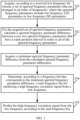
- FIG. 1 is a schematic flowchart of a method for predicting a high frequency excitation signal disclosed by an embodiment of the present invention. As shown in FIG. 1 , the method for predicting a high frequency excitation signal may include the following steps:
- each low frequency LSF parameter or low frequency ISF parameter further corresponds to a frequency
- frequencies corresponding to low frequency LSF parameters or low frequency ISF parameters are usually arranged in ascending order
- a set of spectral frequency parameters that are arranged in an order of frequencies are a set of spectral frequency parameters that are that are arranged in an order of frequencies that correspond to the spectral frequency parameters.
- the set of spectral frequency parameters that are arranged in an order of frequencies may be acquired by a decoder according to the received low frequency bitstream.
- the decoder may be a decoder in an AMR-WB voice codec, or may be a voice decoder, a low frequency bitstream decoder, or the like of another type, which is not limited in this embodiment of the present invention.
- the decoder in this embodiment of the present invention may include at least one processor, and the decoder may work under control of the at least one processor.
- the decoder may first directly decode the low frequency bitstream sent by the encoder to obtain line spectral pair (LSP) parameters, and then convert the LSP parameters to low frequency LSF parameters; or the decoder may first directly decode the low frequency bitstream sent by the encoder to obtain immittance spectral pair (ISP) parameters, and then convert the ISP parameters to low frequency ISF parameters.
- LSP line spectral pair
- ISP immittance spectral pair
- the decoder may perform decoding according to the received low frequency bitstream, to obtain a low frequency signal, and calculate, according to the low frequency signal, the set of spectral frequency parameters that are arranged in an order of frequencies.
- the decoder may calculate LPC coefficients according to the low frequency signal, and then convert the LPC coefficients to LSF parameters or ISF parameters, where a specific calculation process in which the LPC coefficients are converted to the LSF parameters or ISF parameters is also common knowledge known by a person skilled in the art, and is also not described in detail herein in this embodiment of the present invention.
- spectral frequency parameter difference For the acquired set of spectral frequency parameters, calculate a spectral frequency parameter difference between every two spectral frequency parameters that have a same position interval in some or all of the spectral frequency parameters.
- the decoder may select some spectral frequency parameters from the acquired set of spectral frequency parameters, and calculate a spectral frequency parameter difference between every two spectral frequency parameter, which have a same position interval, in the selected spectral frequency parameters.
- the decoder may select all spectral frequency parameters from the acquired set of spectral frequency parameters, and calculate a spectral frequency parameter difference between every two spectral frequency parameter, which have a same position interval, in all the selected spectral frequency parameters.
- either the some or all the spectral frequency parameters are spectral frequency parameters in the acquired set of spectral frequency parameters.
- the decoder may calculate, for this acquired set of spectral frequency parameters, a spectral frequency parameter difference between every two spectral frequency parameters, which have a same position interval, in (some or all of) this set of frequency parameters.
- the every two spectral frequency parameters that have a same position interval include every two spectral frequency parameters whose positions are adjacent, which for example, may be every two low frequency LSF parameters whose positions are adjacent (that is, a position interval is 0 LSF parameter) in a set of low frequency LSF parameters that are arranged in ascending order of frequencies, or may be every two low frequency ISF parameters whose positions are adjacent (that is, a position interval is 0 ISF parameters) in a set of low frequency ISF parameters that are arranged in ascending order of frequencies.
- the every two spectral frequency parameters that have a same position interval include every two spectral frequency parameters whose positions are spaced by a same quantity (such as one or two) of spectral frequency parameters, which for example, may be LSF [1] and LSF [3], LSF [2] and LSF [4], LSF [3] and LSF [5], or the like in a set of low frequency LSF parameters that are arranged in ascending order of frequencies, where position intervals of LSF [1] and LSF [3], LSF [2] and LSF [4], and LSF [3] and LSF [5] are all one LSF parameter, that is LSF [2], LSF [3], and LSF [4].
- the decoder may acquire the minimum spectral frequency parameter difference from the calculated spectral frequency parameter differences.
- the decoder determines according to the two frequency bins, the start frequency bin for predicting the high frequency excitation signal from the low frequency. For example, the decoder may use a smaller frequency bin in the two frequency bin as the start frequency bin for predicting the high frequency excitation signal from the low frequency, or the decoder may use a greater frequency bin in the two frequency bins as the start frequency bin for predicting the high frequency excitation signal from the low frequency, or the decoder may use a frequency bin located between the two frequency bins as the start frequency bin for predicting the high frequency excitation signal from the low frequency, that is, the selected start frequency bin is greater than or equal to the smaller frequency bin in the two frequency bins, and is less than or equal to the greater frequency bin in the two frequency bins; and specific selection of the start frequency bin is not limited in this embodiment of the present invention.
- the decoder may use a minimum frequency bin corresponding to LSF [2] as the start frequency bin for predicting the high frequency excitation signal from the low frequency, or the decoder may use a maximum frequency bin corresponding to LSF [4] as the start frequency bin for predicting the high frequency excitation signal from the low frequency, or the decoder may use a frequency bin in a frequency bin range between a minimum frequency bin that corresponds to LSF [2] and a maximum frequency bin that corresponds to LSF [4] as the start frequency bin for predicting the high frequency excitation signal from the low frequency, which is not limited in this embodiment of the present invention.
- the decoder predicts the high frequency excitation signal from the low frequency.
- the decoder selects, from a low frequency excitation signal that corresponds to a low frequency bitstream, a frequency band with preset bandwidth as a high frequency excitation signal according to a start frequency bin.
- a decoder may calculate a spectral frequency parameter difference between every two spectral frequency parameters, which have a same position interval, in this set of the spectral frequency parameters, and further acquire a minimum spectral frequency parameter difference from the calculated spectral frequency parameter differences, where the spectral frequency parameters include low frequency line spectral frequency (LSF) parameters or low frequency immittance spectral frequency (ISF) parameters, and therefore, the minimum spectral frequency parameter difference is a minimum LSF parameter difference or a minimum ISF parameter difference.
- LSF low frequency line spectral frequency
- ISF low frequency immittance spectral frequency
- the decoder determines, according to a frequency bin that corresponds to the minimum spectral frequency parameter difference (that is, the minimum LSF parameter difference or the minimum ISF parameter difference), a start frequency bin for predicting a high frequency excitation signal from a low frequency, and predicts the high frequency excitation signal from the low frequency according to the start frequency bin of the high frequency excitation signal, which can implement prediction of a high frequency excitation signal that have good coding quality, so that the high frequency excitation signal can be better predicted, thereby effectively improving performance of the high frequency excitation signal.
- the minimum spectral frequency parameter difference that is, the minimum LSF parameter difference or the minimum ISF parameter difference
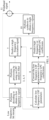
- FIG. 2 is a schematic diagram of a process of predicting a high frequency excitation signal disclosed by an embodiment of the present invention. As shown in FIG. 2 , the process of predicting a high frequency excitation signal is:
- the decoder determines, according to a rate of the low frequency bitstream, a range for searching for the minimum MIN_LSF_DIFF, that is, a position of a highest frequency that corresponds to LSF_DIFF, where a higher rate indicates a larger search range, and a lower rate indicates a smaller search range.
- a rate is less than or equal to 8.85 kbps
- a maximum value of i is M -8
- a maximum value of i is M -6
- a maximum value of i is M -4.
- a correction factor ⁇ is first used to correct LSF_DIFF, where ⁇ decreases with increase of a frequency, that is: ⁇ * LSF_DIFF[ i ] ⁇ MIN_LSF_DIFF, where i ⁇ M, and 0 ⁇ ⁇ ⁇ 1.
- the decoder determines, according to a frequency bin that corresponds to the minimum MIN_LSF_DIFF, a start frequency bin for predicting a high frequency excitation signal from a low frequency.
- the decoder performs decoding according to the received low frequency bitstream, to obtain a low frequency excitation signal.
- the decoder selects, from the low frequency excitation signal, a frequency band with preset bandwidth as the high frequency excitation signal according to the start frequency bin.
- process of predicting a high frequency excitation signal shown in FIG. 2 may further include:
- the decoder converts the low frequency LSF parameters obtained by means of decoding to low frequency LPC coefficients.
- the decoder synthesizes a low frequency signal by using the low frequency LPC coefficients and the low frequency excitation signal.
- the decoder predicts high frequency or wideband LPC coefficients according to the low frequency LPC coefficients.
- the decoder synthesizes a high frequency signal by using the high frequency excitation signal and the high frequency or wideband LPC coefficients.
- the decoder combines the low frequency signal with the high frequency signal, to obtain a wideband signal.
- a signal, whose frequency band is adjacent to that of a high frequency signal, in a low frequency excitation signal obtained by means of decoding is fixedly selected as a high frequency excitation signal; for example, in an AMR-WB, when a rate is greater than or equal to 23.05 kbps, a signal of a frequency band of 4 to 6 kHz is fixedly selected as a high frequency excitation signal of 6 to 8 kHz.
- the LSF parameters may also be replaced by ISF parameters, which does not affect implementation of the present invention.
- a decoder predicts a high frequency excitation signal from a low frequency excitation signal according to a start frequency bin of the high frequency excitation signal, which can implement prediction of a high frequency excitation signal that have good coding quality, so that the high frequency excitation signal can be better predicted, thereby effectively improving performance of the high frequency excitation signal. Further, after the decoder combines a low frequency signal with a high frequency signal, performance of a wideband signal can also be improved.
- FIG. 3 is a schematic diagram of another process of predicting a high frequency excitation signal disclosed by an embodiment (not encompassed by the claims). As shown in FIG. 3 , the process of predicting a high frequency excitation signal is:
- the decoder may determine, according to a rate of the low frequency bitstream, a range for searching for the minimum MIN _LSF_DIFF, that is, a position of a highest frequency that corresponds to LSF_DIFF, where a higher rate indicates a larger search range, and a lower rate indicates a smaller search range.
- a rate is less than or equal to 8.85 kbps
- a maximum value of i is M -8
- a maximum value of i is M -6
- a maximum value of i is M -4.
- a correction factor ⁇ may be used to correct MIN_LSF_DIFF, where ⁇ decreases with increase of a frequency, that is: LSF _ DIFF i ⁇ ⁇ ⁇ MIN_LSF_DIFF , where i ⁇ M , and ⁇ > 1 .
- the decoder determines, according to a frequency bin that corresponds to the minimum MIN_LSF_DIFF, a start frequency bin for predicting a high frequency excitation signal from a low frequency.
- the decoder performs decoding according to the received low frequency bitstream, to obtain a low frequency excitation signal.
- the decoder selects, from the low frequency excitation signal, a frequency band with preset bandwidth as the high frequency excitation signal according to the start frequency bin.
- process of predicting a high frequency excitation signal shown in FIG. 3 may further include:
- a signal, whose frequency band is adjacent to that of a high frequency signal, in a low frequency excitation signal obtained by means of decoding may be fixedly selected as a high frequency excitation signal; for example, in an AMR-WB, when a rate is greater than or equal to 23.05 kbps, a signal of a frequency band of 4 to 6 kHz may be fixedly selected as a high frequency excitation signal of 6 to 8 kHz.
- the LSF parameters may also be replaced by ISF parameters, which does not affect implementation of the present invention.
- a decoder predicts a high frequency excitation signal from a low frequency excitation signal according to a start frequency bin of the high frequency excitation signal, which can implement prediction of a high frequency excitation signal that have good coding quality, so that the high frequency excitation signal can be better predicted, thereby effectively improving performance of the high frequency excitation signal. Further, after the decoder combines a low frequency signal with a high frequency signal, performance of a wideband signal can also be improved.
- FIG. 4 is a schematic diagram of another process of predicting a high frequency excitation signal disclosed by an embodiment of the present invention. As shown in FIG. 4 , the process of predicting a high frequency excitation signal is:
- the decoder determines, according to a rate of the low frequency bitstream, a range for searching for the minimum MIN_LSF_DIFF, that is, a position of a highest frequency that corresponds to LSF_DIFF, where a higher rate indicates a larger search range, and a lower rate indicates a smaller search range.
- a rate is less than or equal to 8.85 kbps
- a maximum value of i is M -8
- a maximum value of i is M -6
- a maximum value of i is M -4.
- a correction factor ⁇ may be used to correct LSF_DIFF, where ⁇ decreases with increase of a frequency, that is: ⁇ ⁇ LSF _ DIFF i ⁇ MIN_LSF_DIFF , where i ⁇ M , and 0 ⁇ ⁇ ⁇ 1 .
- the decoder determines, according to a frequency bin that corresponds to the minimum MIN_LSF_DIFF, a start frequency bin for predicting a high frequency excitation signal from a low frequency.
- the decoder processes the low-frequency signal by using an LPC analysis filter, to obtain a low frequency excitation signal.
- the decoder selects, from the low frequency excitation signal, a frequency band with preset bandwidth as the high frequency excitation signal according to the start frequency bin.
- process of predicting a high frequency excitation signal shown in FIG. 4 may further include:
- a signal, whose frequency band is adjacent to that of a high frequency signal, in a low frequency signal obtained by means of decoding is fixedly selected as a high frequency excitation signal; for example, in an AMR-WB, when a rate is greater than or equal to 23.05 kbps, a signal of a frequency band of 4 to 6 kHz may be fixedly selected as a high frequency excitation signal of 6 to 8 kHz.
- the LSF parameters may also be replaced by ISF parameters, which does not affect implementation of the present invention.
- a decoder predicts a high frequency excitation signal from a low frequency signal according to a start frequency bin of the high frequency excitation signal, which can implement prediction of a high frequency excitation signal that have good coding quality, so that the high frequency excitation signal can be better predicted, thereby effectively improving performance of the high frequency excitation signal. Further, after the decoder combines a low frequency signal with a high frequency signal, performance of a wideband signal can also be improved.
- FIG. 5 is a schematic diagram of another process of predicting a high frequency excitation signal disclosed by an embodiment (not encompassed by the claims). As shown in FIG. 5 , the process of predicting a high frequency excitation signal is:
- the decoder may determine, according to a rate of the low frequency bitstream, a range for searching for the minimum MIN_LSF_DIFF, that is, a position of a highest frequency corresponding to LSF_DIFF, where a higher rate indicates a larger search range, and a lower rate indicates a smaller search range.
- a rate is less than or equal to 8.85 kbps
- a maximum value of i is M -8
- a maximum value of i is M -6
- a maximum value of i is M -4.
- a correction factor ⁇ may be used to correct MIN_LSF_DIFF, where ⁇ decreases with increase of a frequency, that is: LSF_DIFF i ⁇ ⁇ ⁇ MIN_LSF_DIFF , where i ⁇ M , and ⁇ > 1 .
- the decoder determines, according to a frequency bin that corresponds to the minimum MIN_LSF_DIFF, a start frequency bin for predicting a high frequency excitation signal from a low frequency.
- the decoder processes the low-frequency signal by using an LPC analysis filter, to obtain a low frequency excitation signal.
- the decoder selects, from the low frequency excitation signal, a frequency band with preset bandwidth as the high frequency excitation signal according to the start frequency bin.
- the process of predicting a high frequency excitation signal shown in FIG. 5 may further include: 8.
- the decoder predicts a high frequency envelope according to the low frequency signal.
- the decoder may predict the high frequency envelope according to low frequency LPC coefficients and the low frequency excitation signal.
- the decoder synthesizes a high frequency signal by using the high frequency excitation signal and the high frequency envelope.
- the decoder combines the low frequency signal with the high frequency signal, to obtain a wideband signal.
- a signal, whose frequency band is adjacent to that of a high frequency signal, in a low frequency signal obtained by means of decoding may be fixedly selected as a high frequency excitation signal; for example, in an AMR-WB, when a rate is greater than or equal to 23.05 kbps, a signal of a frequency band of 4 to 6 kHz may be fixedly selected as a high frequency excitation signal of 6 to 8 kHz.
- the LSF parameters may also be replaced by ISF parameters, which does not affect implementation of the present invention.
- a decoder predicts a high frequency excitation signal from a low frequency signal according to a start frequency bin of the high frequency excitation signal, which can implement prediction of a high frequency excitation signal that have good coding quality, so that the high frequency excitation signal can be better predicted, thereby effectively improving performance of the high frequency excitation signal. Further, after the decoder combines a low frequency signal with a high frequency signal, performance of a wideband signal can also be improved.
- FIG. 6 is a schematic structural diagram of an apparatus for predicting a high frequency excitation signal disclosed by an embodiment of the present invention.
- the apparatus for predicting a high frequency excitation signal shown in FIG. 6 may be physically implemented as an independent device, or may be used as a newly added part of a decoder, which is not limited in this embodiment of the present invention.
- the apparatus for predicting a high frequency excitation signal may include:
- the first acquiring unit 601 may be specifically configured to perform decoding according to the received low frequency bitstream, to obtain the set of spectral frequency parameters that are arranged in an order of frequencies; or is specifically configured to perform decoding according to the received low frequency bitstream, to obtain a low frequency signal, and calculate, according to the low frequency signal, the set of spectral frequency parameters that are arranged in an order of frequencies.
- the every two spectral frequency parameters that have a same position interval include every two adjacent spectral frequency parameters or every two spectral frequency parameters spaced by a same quantity of spectral frequency parameters.
- the apparatus for predicting a high frequency excitation signal described in FIG. 6 can predict a high frequency excitation signal from a low frequency excitation signal according to a start frequency bin of a high frequency excitation signal, which can implement prediction of a high frequency excitation signal that have good coding quality, so that the high frequency excitation signal can be better predicted, thereby effectively improving performance of the high frequency excitation signal.
- FIG. 7 is a schematic structural diagram of another apparatus for predicting a high frequency excitation signal disclosed by an embodiment of the present invention.
- the apparatus for predicting a high frequency excitation signal shown in FIG. 7 is obtained by optimizing the apparatus for predicting a high frequency excitation signal shown in FIG. 6 .
- the apparatus for predicting a high frequency excitation signal shown in FIG. 7 if the first acquiring unit 601 is specifically configured to perform decoding according to the received low frequency bitstream, to obtain the set of spectral frequency parameters that are arranged in an order of frequencies, in addition to all the units of the apparatus for predicting a high frequency excitation signal shown in FIG. 6 , the apparatus for predicting a high frequency excitation signal shown in FIG. 7 may further include:
- the apparatus for predicting a high frequency excitation signal shown in FIG. 7 may further include:
- FIG. 8 is a schematic structural diagram of another apparatus for predicting a high frequency excitation signal disclosed by an embodiment of the present invention.
- the apparatus for predicting a high frequency excitation signal shown in FIG. 8 is obtained by optimizing the apparatus for predicting a high frequency excitation signal shown in FIG. 6 .
- the apparatus for predicting a high frequency excitation signal shown in FIG. 8 if the first acquiring unit 601 is specifically configured to perform decoding according to the received low frequency bitstream, to obtain the set of spectral frequency parameters that are arranged in an order of frequencies, in addition to all the units of the apparatus for predicting a high frequency excitation signal shown in FIG. 6 , the apparatus for predicting a high frequency excitation signal shown in FIG.
- the 8 also further includes a decoding unit 606, configured to decode the received low frequency bitstream, to obtain a low frequency excitation signal; and correspondingly, the high frequency excitation prediction unit 605 is also configured to select, from the low frequency excitation signal obtained by means of decoding by the decoding unit 606, a frequency band with preset bandwidth as the high frequency excitation signal according to the start frequency bin determined by the start frequency bin determining unit 604.
- the apparatus for predicting a high frequency excitation signal shown in FIG. 8 may further include:
- FIG. 9 is a schematic structural diagram of another apparatus for predicting a high frequency excitation signal disclosed by an embodiment of the present invention.
- the apparatus for predicting a high frequency excitation signal shown in FIG. 9 is obtained by optimizing the apparatus for predicting a high frequency excitation signal shown in FIG. 6 .
- the apparatus for predicting a high frequency excitation signal shown in FIG. 9 is obtained by optimizing the apparatus for predicting a high frequency excitation signal shown in FIG. 6 .
- the high frequency excitation prediction unit 605 is specifically configured to process the low-frequency signal by using an LPC analysis filter (which may be included in the high frequency excitation prediction unit 605), to obtain a low frequency excitation signal, and select, from the low frequency excitation signal, a frequency band with preset bandwidth as the high frequency excitation signal according to the start frequency bin determined by the start frequency bin determining unit 604.
- the apparatus for predicting a high frequency excitation signal shown in FIG. 9 may further include:
- FIG. 10 is a schematic structural diagram of another apparatus for predicting a high frequency excitation signal disclosed by an embodiment of the present invention.
- the apparatus for predicting a high frequency excitation signal shown in FIG. 10 is obtained by optimizing the apparatus for predicting a high frequency excitation signal shown in FIG. 6 .
- the apparatus for predicting a high frequency excitation signal shown in FIG. 10 is obtained by optimizing the apparatus for predicting a high frequency excitation signal shown in FIG. 6 .
- the first acquiring unit 601 is also configured to perform decoding according to the received low frequency bitstream, to obtain a low frequency signal, and calculate, according to the low frequency signal, the set of spectral frequency parameters that are arranged in an order of frequencies; and the high frequency excitation prediction unit 605 may also be configured to process the low-frequency signal by using an LPC analysis filter (which may be included in the high frequency excitation prediction unit 605), to obtain a low frequency excitation signal, and select, from the low frequency excitation signal, a frequency band with preset bandwidth as a high frequency excitation signal according to the start frequency bin determined by the start frequency bin determining unit 604.
- LPC analysis filter which may be included in the high frequency excitation prediction unit 605
- the apparatus for predicting a high frequency excitation signal shown in FIG. 10 may further include:
- the apparatuses for predicting a high frequency excitation signal described in FIG. 7 to FIG. 10 can predict a high frequency excitation signal from a low frequency excitation signal or a low frequency signal according to a start frequency bin of the high frequency excitation signal, which can implement prediction of a high frequency excitation signal that has good coding quality, so that the high frequency excitation signal can be better predicted, thereby effectively improving performance of the high frequency excitation signal. Further, after the apparatuses for predicting a high frequency excitation signal described in FIG. 7 to FIG. 10 combines a low frequency signal with a high frequency signal, performance of a wideband signal can also be improved.
- FIG. 11 is a schematic structural diagram of a decoder disclosed by an embodiment of the present invention, which is configured to perform the method for predicting a high frequency excitation signal disclosed by the embodiment of the present invention.
- the decoder 1100 includes: at least one processor 1101, such as a CPU, at least one network interface 1104, a user interface 1103, a memory 1105, and at least one communications bus 1102.
- the communications bus 1102 is configured to implement a connection and communication between these components.
- the user interface 1103 may include a USB interface, or another standard interface or wired interface.
- the network interface 1104 may include a Wi-Fi interface, or another wireless interface.
- the memory 1105 may include a high-speed RAM memory, or may further include a non-volatile memory, such as at least one magnetic disk storage.
- the memory 1105 may include at least one storage apparatus located far away from the foregoing processor 1101.
- the network interface 1104 receives a low frequency bitstream sent by an encoder;
- the user interface 1103 may be connected to a peripheral device, and configured to output a signal;
- the memory 1105 may be configured to store a program, and the processor 1101 may be configured to invoke the program stored in the memory 1105, and perform the following operations:
- the acquiring, by the processor 1101 according to the received low frequency bitstream, a set of spectral frequency parameters that are arranged in an order of frequencies may include:
- the processor 1101 may further perform the following operations: performing decoding according to the received low frequency bitstream, to obtain a low frequency excitation signal.
- the predicting, by the processor 1101, the high frequency excitation signal from the low frequency according to the start frequency bin includes: selecting, from the low frequency excitation signal, a frequency band with preset bandwidth as the high frequency excitation signal according to the start frequency bin.
- processor 1101 may further perform the following operations:
- processor 1101 may further perform the following operations:
- the processor 11101 performs decoding according to the received low frequency bitstream, to obtain the low frequency signal, and calculates, according to the low frequency signal, the set of spectral frequency parameters that are arranged in an order of frequencies, the predicting, by the processor 1101, the high frequency excitation signal from the low frequency according to the start frequency bin includes:
- processor 1101 may further perform the following operations:
- processor 1101 may further perform the following operations:
- the decoder described in FIG. 11 can predict a high frequency excitation signal from a low frequency excitation signal or a low frequency signal according to a start frequency bin of the high frequency excitation signal, which can implement prediction of a high frequency excitation signal that have good coding quality, so that the high frequency excitation signal can be better predicted, thereby effectively improving performance of the high frequency excitation signal. Further, after the decoder described in FIG. 11 combines a low frequency signal with a high frequency signal, performance of a wideband signal can also be improved.
- the program may be stored in a computer readable storage medium.
- the storage medium may include a flash memory, a read-only memory (ROM), a random access memory (RAM), a magnetic disk, and an optical disk.
Landscapes
- Engineering & Computer Science (AREA)
- Physics & Mathematics (AREA)
- Acoustics & Sound (AREA)
- Multimedia (AREA)
- Signal Processing (AREA)
- Health & Medical Sciences (AREA)
- Audiology, Speech & Language Pathology (AREA)
- Human Computer Interaction (AREA)
- Computational Linguistics (AREA)
- Quality & Reliability (AREA)
- Spectroscopy & Molecular Physics (AREA)
- Compression, Expansion, Code Conversion, And Decoders (AREA)
- Digital Transmission Methods That Use Modulated Carrier Waves (AREA)
- Position Fixing By Use Of Radio Waves (AREA)
- Other Investigation Or Analysis Of Materials By Electrical Means (AREA)
- Measuring Frequencies, Analyzing Spectra (AREA)
Claims (11)
- Procédé de prédiction d'un signal d'excitation en bande hautes fréquences, comprenant :l'acquisition (101), par un décodeur vocal, selon un flux binaire en bande basses fréquences reçu, d'un ensemble de paramètres de fréquence spectrale agencés par ordre de fréquences, les paramètres de fréquence spectrale comprenant des paramètres de fréquence de raie spectrale, notée LSF, en bande basses fréquences ;le calcul (102), par le décodeur vocal, de différences de paramètres de fréquence spectrale entre tous les deux paramètres de fréquence spectrale adjacents selon l'ordre de fréquences ;la détermination, par le décodeur vocal, selon un débit du flux binaire en bande basses fréquences, d'une plage de recherche pour la recherche d'une différence de paramètres de fréquence spectrale minimale ;la correction, par le décodeur vocal, de chaque différence de paramètres de fréquence spectrale calculée dans la plage de recherche à l'aide d'un facteur de correction afin d'obtenir une pluralité de différences de paramètres de fréquence spectrale corrigées, le facteur de correction diminuant à mesure qu'une fréquence augmente, et le facteur de correction étant supérieur à 0 et inférieur à 1 ;la recherche (103), par le décodeur vocal, de la différence de paramètres de fréquence spectrale minimale parmi les différences de paramètres de fréquence spectrale corrigées ;la détermination (104), par le décodeur vocal, selon un bin de fréquence qui correspond à la différence de paramètres de fréquence spectrale minimale, d'un bin de fréquence de début pour la prédiction d'un signal d'excitation en bande haute à partir d'une bande basses fréquences ; etla prédiction (105), par le décodeur vocal, du signal d'excitation en bande hautes fréquences par sélection, comme signal d'excitation en bande hautes fréquences, à partir d'un signal d'excitation en bande basses fréquences qui correspond au flux binaire en bande basses fréquences, d'une bande de fréquences ayant une largeur de bande prédéfinie selon le bin de fréquence de début ; lorsque le débit est supérieur à un seuil donné, un signal ayant une bande de fréquences adjacente à un signal haute fréquence dans le signal d'excitation basse fréquence obtenu par décodage étant sélectionné de manière fixe comme signal d'excitation haute fréquence.
- Procédé selon la revendication 1, l'ensemble de paramètres de fréquence spectrale étant acquis par décodage du flux binaire en bande basses fréquences reçu.
- Procédé selon la revendication 2, comprenant en outre :
le décodage du flux binaire en bande basse reçu afin d'obtenir le signal d'excitation en bande basse. - Procédé selon la revendication 3, le procédé comprenant en outre :la conversion des paramètres de fréquence spectrale obtenus par décodage en coefficients du type coefficient de prédiction linéaire, noté LPC, en bande basses fréquences ;la synthèse d'un signal en bande basses fréquences au moyen des coefficients LPC en bande basses fréquences et du signal d'excitation en bande basses fréquences ;la prédiction de coefficients LPC en bande hautes fréquences ou en bande large selon les coefficients LPC en bande basses fréquences ;la synthèse d'un signal en bande hautes fréquences au moyen du signal d'excitation en bande hautes fréquences et des coefficients LPC en bande hautes fréquences ou en bande large ; etla combinaison du signal en bande basses fréquences avec le signal en bande hautes fréquences afin d'obtenir un signal en bande large.
- Procédé selon la revendication 2, l'ensemble de paramètres de fréquence spectrale étant calculé selon le signal en bande basses fréquences, le procédé comprenant en outre :
le traitement du signal basse fréquence au moyen d'un filtre d'analyse LPC afin d'obtenir le signal d'excitation en bande basses fréquences. - Procédé selon la revendication 5, le procédé comprenant en outre :la conversion des paramètres de fréquence spectrale calculés obtenus en coefficients du type coefficient de prédiction linéaire, noté LPC, en bande basses fréquences ;la prédiction de coefficients LPC en bande hautes fréquences ou en bande large selon les coefficients LPC en bande basses fréquences ;la synthèse d'un signal en bande hautes fréquences au moyen du signal d'excitation en bande hautes fréquences et des coefficients LPC en bande hautes fréquences ou en bande large ; etla combinaison du signal en bande basses fréquences avec le signal en bande hautes fréquences afin d'obtenir un signal en bande large.
- Procédé selon l'une quelconque des revendications 1 à 6, un débit plus élevé du flux binaire en bande basses fréquences indiquant une plage de recherche plus grande, et un débit plus faible du flux binaire en bande basses fréquences indiquant une plage de recherche plus petite.
- Procédé selon l'une quelconque des revendications 1 à 7, lorsqu'un débit est supérieur ou égal à 23,05 kbps, un signal d'une bande de fréquences de 4 à 6 kHz étant sélectionné comme signal d'excitation haute fréquence de 6 à 8 kHz.
- Décodeur, comprenant : un processeur et une mémoire ; la mémoire stockant des instructions qui, lorsqu'elles sont exécutées par le processeur, amènent le processeur à réaliser les étapes de l'une quelconque des revendications 1 à 8.
- Support de stockage lisible par ordinateur stockant des instructions qui, lorsqu'elles sont exécutées par un processeur, amènent le processeur à réaliser les étapes de l'une quelconque des revendications 1 à 8.
- Produit-programme d'ordinateur, comprenant des instructions qui, lorsqu'elles sont exécutées par un processeur, amènent le processeur à réaliser les étapes de l'une quelconque des revendications 1 à 8.
Priority Applications (1)
| Application Number | Priority Date | Filing Date | Title |
|---|---|---|---|
| EP23208114.1A EP4339946A3 (fr) | 2013-09-26 | 2014-04-03 | Procédé et appareil de prédiction de signal d'excitation haute fréquence |
Applications Claiming Priority (3)
| Application Number | Priority Date | Filing Date | Title |
|---|---|---|---|
| CN201310444734.4A CN104517611B (zh) | 2013-09-26 | 2013-09-26 | 一种高频激励信号预测方法及装置 |
| PCT/CN2014/074711 WO2015043151A1 (fr) | 2013-09-26 | 2014-04-03 | Procédé et dispositif de prédiction de signal d'excitation à haute fréquence |
| EP14849584.9A EP3051534B1 (fr) | 2013-09-26 | 2014-04-03 | Procédé et dispositif de prédiction de signal d'excitation à haute fréquence |
Related Parent Applications (2)
| Application Number | Title | Priority Date | Filing Date |
|---|---|---|---|
| EP14849584.9A Division-Into EP3051534B1 (fr) | 2013-09-26 | 2014-04-03 | Procédé et dispositif de prédiction de signal d'excitation à haute fréquence |
| EP14849584.9A Division EP3051534B1 (fr) | 2013-09-26 | 2014-04-03 | Procédé et dispositif de prédiction de signal d'excitation à haute fréquence |
Related Child Applications (2)
| Application Number | Title | Priority Date | Filing Date |
|---|---|---|---|
| EP23208114.1A Division EP4339946A3 (fr) | 2013-09-26 | 2014-04-03 | Procédé et appareil de prédiction de signal d'excitation haute fréquence |
| EP23208114.1A Division-Into EP4339946A3 (fr) | 2013-09-26 | 2014-04-03 | Procédé et appareil de prédiction de signal d'excitation haute fréquence |
Publications (2)
| Publication Number | Publication Date |
|---|---|
| EP3573057A1 EP3573057A1 (fr) | 2019-11-27 |
| EP3573057B1 true EP3573057B1 (fr) | 2024-06-05 |
Family
ID=52741932
Family Applications (3)
| Application Number | Title | Priority Date | Filing Date |
|---|---|---|---|
| EP23208114.1A Pending EP4339946A3 (fr) | 2013-09-26 | 2014-04-03 | Procédé et appareil de prédiction de signal d'excitation haute fréquence |
| EP14849584.9A Active EP3051534B1 (fr) | 2013-09-26 | 2014-04-03 | Procédé et dispositif de prédiction de signal d'excitation à haute fréquence |
| EP18203903.2A Active EP3573057B1 (fr) | 2013-09-26 | 2014-04-03 | Procédé et dispositif de prédiction de signal d'excitation à haute fréquence |
Family Applications Before (2)
| Application Number | Title | Priority Date | Filing Date |
|---|---|---|---|
| EP23208114.1A Pending EP4339946A3 (fr) | 2013-09-26 | 2014-04-03 | Procédé et appareil de prédiction de signal d'excitation haute fréquence |
| EP14849584.9A Active EP3051534B1 (fr) | 2013-09-26 | 2014-04-03 | Procédé et dispositif de prédiction de signal d'excitation à haute fréquence |
Country Status (16)
| Country | Link |
|---|---|
| US (3) | US9685165B2 (fr) |
| EP (3) | EP4339946A3 (fr) |
| JP (2) | JP6420324B2 (fr) |
| KR (2) | KR101805794B1 (fr) |
| CN (2) | CN105761723B (fr) |
| AU (1) | AU2014328353B2 (fr) |
| BR (1) | BR112016006583B1 (fr) |
| CA (1) | CA2924952C (fr) |
| ES (1) | ES2716152T3 (fr) |
| MX (1) | MX353022B (fr) |
| MY (1) | MY166226A (fr) |
| PL (1) | PL3573057T3 (fr) |
| RU (1) | RU2637885C2 (fr) |
| SG (1) | SG11201602225WA (fr) |
| WO (1) | WO2015043151A1 (fr) |
| ZA (2) | ZA201601991B (fr) |
Families Citing this family (7)
| Publication number | Priority date | Publication date | Assignee | Title |
|---|---|---|---|---|
| CN104217727B (zh) * | 2013-05-31 | 2017-07-21 | 华为技术有限公司 | 信号解码方法及设备 |
| FR3008533A1 (fr) * | 2013-07-12 | 2015-01-16 | Orange | Facteur d'echelle optimise pour l'extension de bande de frequence dans un decodeur de signaux audiofrequences |
| CN105761723B (zh) * | 2013-09-26 | 2019-01-15 | 华为技术有限公司 | 一种高频激励信号预测方法及装置 |
| CN104517610B (zh) | 2013-09-26 | 2018-03-06 | 华为技术有限公司 | 频带扩展的方法及装置 |
| EP3483881B1 (fr) * | 2013-11-13 | 2024-10-02 | Fraunhofer-Gesellschaft zur Förderung der angewandten Forschung e.V. | Codeur de codage d'un signal audio, système de transmission audio et procédé permettant de déterminer des valeurs de correction |
| TWI901542B (zh) | 2017-03-23 | 2025-10-11 | 瑞典商都比國際公司 | 用於音訊信號之高頻重建的諧波轉置器的回溯相容整合 |
| CN107818797B (zh) * | 2017-12-07 | 2021-07-06 | 苏州科达科技股份有限公司 | 语音质量评价方法、装置及其系统 |
Family Cites Families (50)
| Publication number | Priority date | Publication date | Assignee | Title |
|---|---|---|---|---|
| US5455888A (en) * | 1992-12-04 | 1995-10-03 | Northern Telecom Limited | Speech bandwidth extension method and apparatus |
| JPH0955778A (ja) * | 1995-08-15 | 1997-02-25 | Fujitsu Ltd | 音声信号の広帯域化装置 |
| US7072832B1 (en) * | 1998-08-24 | 2006-07-04 | Mindspeed Technologies, Inc. | System for speech encoding having an adaptive encoding arrangement |
| US7389227B2 (en) * | 2000-01-14 | 2008-06-17 | C & S Technology Co., Ltd. | High-speed search method for LSP quantizer using split VQ and fixed codebook of G.729 speech encoder |
| CN1324558C (zh) * | 2001-11-02 | 2007-07-04 | 松下电器产业株式会社 | 编码设备,解码设备以及音频数据分配系统 |
| DE60202881T2 (de) | 2001-11-29 | 2006-01-19 | Coding Technologies Ab | Wiederherstellung von hochfrequenzkomponenten |
| US7363218B2 (en) * | 2002-10-25 | 2008-04-22 | Dilithium Networks Pty. Ltd. | Method and apparatus for fast CELP parameter mapping |
| KR100499047B1 (ko) * | 2002-11-25 | 2005-07-04 | 한국전자통신연구원 | 서로 다른 대역폭을 갖는 켈프 방식 코덱들 간의 상호부호화 장치 및 그 방법 |
| RU2248619C2 (ru) * | 2003-02-12 | 2005-03-20 | Рыболовлев Александр Аркадьевич | Способ и устройство преобразования речевого сигнала методом линейного предсказания с адаптивным распределением информационных ресурсов |
| DE602004032587D1 (de) * | 2003-09-16 | 2011-06-16 | Panasonic Corp | Codierungsvorrichtung und Decodierungsvorrichtung |
| CA2457988A1 (fr) * | 2004-02-18 | 2005-08-18 | Voiceage Corporation | Methodes et dispositifs pour la compression audio basee sur le codage acelp/tcx et sur la quantification vectorielle a taux d'echantillonnage multiples |
| KR100647290B1 (ko) * | 2004-09-22 | 2006-11-23 | 삼성전자주식회사 | 합성된 음성의 특성을 이용하여 양자화/역양자화를선택하는 음성 부호화/복호화 장치 및 그 방법 |
| BRPI0608270A2 (pt) * | 2005-04-01 | 2009-10-06 | Qualcomm Inc | sistemas, métodos e equipamento para filtragem anti-dispersão |
| CN101199003B (zh) | 2005-04-22 | 2012-01-11 | 高通股份有限公司 | 用于增益因数衰减的系统、方法和设备 |
| EP1898397B1 (fr) * | 2005-06-29 | 2009-10-21 | Panasonic Corporation | Decodeur scalable et procede d'interpolation de donnees disparues |
| JP2007310296A (ja) * | 2006-05-22 | 2007-11-29 | Oki Electric Ind Co Ltd | 帯域拡張装置及び方法 |
| KR20070115637A (ko) | 2006-06-03 | 2007-12-06 | 삼성전자주식회사 | 대역폭 확장 부호화 및 복호화 방법 및 장치 |
| CN101089951B (zh) * | 2006-06-16 | 2011-08-31 | 北京天籁传音数字技术有限公司 | 频带扩展编码方法及装置和解码方法及装置 |
| US8532984B2 (en) * | 2006-07-31 | 2013-09-10 | Qualcomm Incorporated | Systems, methods, and apparatus for wideband encoding and decoding of active frames |
| US8295507B2 (en) * | 2006-11-09 | 2012-10-23 | Sony Corporation | Frequency band extending apparatus, frequency band extending method, player apparatus, playing method, program and recording medium |
| JP5141180B2 (ja) * | 2006-11-09 | 2013-02-13 | ソニー株式会社 | 周波数帯域拡大装置及び周波数帯域拡大方法、再生装置及び再生方法、並びに、プログラム及び記録媒体 |
| KR101375582B1 (ko) * | 2006-11-17 | 2014-03-20 | 삼성전자주식회사 | 대역폭 확장 부호화 및 복호화 방법 및 장치 |
| US8639500B2 (en) | 2006-11-17 | 2014-01-28 | Samsung Electronics Co., Ltd. | Method, medium, and apparatus with bandwidth extension encoding and/or decoding |
| KR101565919B1 (ko) * | 2006-11-17 | 2015-11-05 | 삼성전자주식회사 | 고주파수 신호 부호화 및 복호화 방법 및 장치 |
| EP3629328A1 (fr) | 2007-03-05 | 2020-04-01 | Telefonaktiebolaget LM Ericsson (publ) | Procédé et agencement pour lisser un bruit de fond stationnaire |
| US8392198B1 (en) * | 2007-04-03 | 2013-03-05 | Arizona Board Of Regents For And On Behalf Of Arizona State University | Split-band speech compression based on loudness estimation |
| KR100921867B1 (ko) * | 2007-10-17 | 2009-10-13 | 광주과학기술원 | 광대역 오디오 신호 부호화 복호화 장치 및 그 방법 |
| CN101458930B (zh) * | 2007-12-12 | 2011-09-14 | 华为技术有限公司 | 带宽扩展中激励信号的生成及信号重建方法和装置 |
| JP4818335B2 (ja) * | 2008-08-29 | 2011-11-16 | 株式会社東芝 | 信号帯域拡張装置 |
| JP4945586B2 (ja) * | 2009-02-02 | 2012-06-06 | 株式会社東芝 | 信号帯域拡張装置 |
| US8463599B2 (en) | 2009-02-04 | 2013-06-11 | Motorola Mobility Llc | Bandwidth extension method and apparatus for a modified discrete cosine transform audio coder |
| JP4932917B2 (ja) | 2009-04-03 | 2012-05-16 | 株式会社エヌ・ティ・ティ・ドコモ | 音声復号装置、音声復号方法、及び音声復号プログラム |
| CN101521014B (zh) * | 2009-04-08 | 2011-09-14 | 武汉大学 | 音频带宽扩展编解码装置 |
| JP5754899B2 (ja) * | 2009-10-07 | 2015-07-29 | ソニー株式会社 | 復号装置および方法、並びにプログラム |
| US8484020B2 (en) * | 2009-10-23 | 2013-07-09 | Qualcomm Incorporated | Determining an upperband signal from a narrowband signal |
| JP2011209548A (ja) * | 2010-03-30 | 2011-10-20 | Nippon Logics Kk | 帯域拡張装置 |
| CN102870156B (zh) * | 2010-04-12 | 2015-07-22 | 飞思卡尔半导体公司 | 音频通信设备、输出音频信号的方法和通信系统 |
| EP2577656A4 (fr) | 2010-05-25 | 2014-09-10 | Nokia Corp | Extenseur de bande passante |
| CN103035248B (zh) * | 2011-10-08 | 2015-01-21 | 华为技术有限公司 | 音频信号编码方法和装置 |
| WO2013066236A2 (fr) * | 2011-11-02 | 2013-05-10 | Telefonaktiebolaget L M Ericsson (Publ) | Codage/décodage audio basé sur une représentation efficace de coefficients auto-régressifs |
| WO2013066238A2 (fr) * | 2011-11-02 | 2013-05-10 | Telefonaktiebolaget L M Ericsson (Publ) | Génération d'une extension à bande haute d'un signal audio à bande passante étendue |
| US9589576B2 (en) * | 2011-11-03 | 2017-03-07 | Telefonaktiebolaget Lm Ericsson (Publ) | Bandwidth extension of audio signals |
| FR2984580A1 (fr) * | 2011-12-20 | 2013-06-21 | France Telecom | Procede de detection d'une bande de frequence predeterminee dans un signal de donnees audio, dispositif de detection et programme d'ordinateur correspondant |
| US9711156B2 (en) * | 2013-02-08 | 2017-07-18 | Qualcomm Incorporated | Systems and methods of performing filtering for gain determination |
| MY172616A (en) * | 2013-03-13 | 2019-12-06 | Telekom Malaysia Berhad | A system for analysing network traffic and a method thereof |
| CN103165134B (zh) * | 2013-04-02 | 2015-01-14 | 武汉大学 | 音频信号高频参数编解码装置 |
| US9666202B2 (en) * | 2013-09-10 | 2017-05-30 | Huawei Technologies Co., Ltd. | Adaptive bandwidth extension and apparatus for the same |
| CN104517610B (zh) * | 2013-09-26 | 2018-03-06 | 华为技术有限公司 | 频带扩展的方法及装置 |
| CN105761723B (zh) * | 2013-09-26 | 2019-01-15 | 华为技术有限公司 | 一种高频激励信号预测方法及装置 |
| US10163447B2 (en) * | 2013-12-16 | 2018-12-25 | Qualcomm Incorporated | High-band signal modeling |
-
2013
- 2013-09-26 CN CN201610228699.6A patent/CN105761723B/zh active Active
- 2013-09-26 CN CN201310444734.4A patent/CN104517611B/zh active Active
-
2014
- 2014-04-03 JP JP2016517389A patent/JP6420324B2/ja active Active
- 2014-04-03 RU RU2016116016A patent/RU2637885C2/ru active
- 2014-04-03 BR BR112016006583-2A patent/BR112016006583B1/pt active IP Right Grant
- 2014-04-03 PL PL18203903.2T patent/PL3573057T3/pl unknown
- 2014-04-03 MY MYPI2016701050A patent/MY166226A/en unknown
- 2014-04-03 MX MX2016003882A patent/MX353022B/es active IP Right Grant
- 2014-04-03 WO PCT/CN2014/074711 patent/WO2015043151A1/fr not_active Ceased
- 2014-04-03 AU AU2014328353A patent/AU2014328353B2/en active Active
- 2014-04-03 CA CA2924952A patent/CA2924952C/fr active Active
- 2014-04-03 EP EP23208114.1A patent/EP4339946A3/fr active Pending
- 2014-04-03 EP EP14849584.9A patent/EP3051534B1/fr active Active
- 2014-04-03 KR KR1020167009849A patent/KR101805794B1/ko active Active
- 2014-04-03 EP EP18203903.2A patent/EP3573057B1/fr active Active
- 2014-04-03 KR KR1020177034721A patent/KR101894927B1/ko active Active
- 2014-04-03 ES ES14849584T patent/ES2716152T3/es active Active
- 2014-04-03 SG SG11201602225WA patent/SG11201602225WA/en unknown
-
2016
- 2016-03-23 ZA ZA2016/01991A patent/ZA201601991B/en unknown
- 2016-03-25 US US15/080,950 patent/US9685165B2/en active Active
-
2017
- 2017-05-16 US US15/596,078 patent/US10339944B2/en active Active
- 2017-10-19 ZA ZA2017/07083A patent/ZA201707083B/en unknown
-
2018
- 2018-10-11 JP JP2018192580A patent/JP6720266B2/ja active Active
-
2019
- 2019-05-20 US US16/417,195 patent/US10607620B2/en active Active
Also Published As
Similar Documents
| Publication | Publication Date | Title |
|---|---|---|
| US10607620B2 (en) | Method and apparatus for predicting high band excitation signal | |
| EP3611729B1 (fr) | Procédé et appareil d'extension de bande passante | |
| JP5571235B2 (ja) | ピッチ調整コーディング及び非ピッチ調整コーディングを使用する信号符号化 | |
| KR101868926B1 (ko) | 노이즈 신호 처리 및 생성 방법, 인코더/디코더 및 인코딩/디코딩 시스템 | |
| US9786293B2 (en) | Signal coding and decoding methods and devices | |
| CN102044250B (zh) | 频带扩展方法及装置 | |
| EP3186808B1 (fr) | Quantification de paramètre audio | |
| HK1206139B (en) | High-frequency excitation signal prediction method and device |
Legal Events
| Date | Code | Title | Description |
|---|---|---|---|
| PUAI | Public reference made under article 153(3) epc to a published international application that has entered the european phase |
Free format text: ORIGINAL CODE: 0009012 |
|
| STAA | Information on the status of an ep patent application or granted ep patent |
Free format text: STATUS: THE APPLICATION HAS BEEN PUBLISHED |
|
| AC | Divisional application: reference to earlier application |
Ref document number: 3051534 Country of ref document: EP Kind code of ref document: P |
|
| AK | Designated contracting states |
Kind code of ref document: A1 Designated state(s): AL AT BE BG CH CY CZ DE DK EE ES FI FR GB GR HR HU IE IS IT LI LT LU LV MC MK MT NL NO PL PT RO RS SE SI SK SM TR |
|
| STAA | Information on the status of an ep patent application or granted ep patent |
Free format text: STATUS: REQUEST FOR EXAMINATION WAS MADE |
|
| 17P | Request for examination filed |
Effective date: 20200527 |
|
| RBV | Designated contracting states (corrected) |
Designated state(s): AL AT BE BG CH CY CZ DE DK EE ES FI FR GB GR HR HU IE IS IT LI LT LU LV MC MK MT NL NO PL PT RO RS SE SI SK SM TR |
|
| STAA | Information on the status of an ep patent application or granted ep patent |
Free format text: STATUS: EXAMINATION IS IN PROGRESS |
|
| 17Q | First examination report despatched |
Effective date: 20201012 |
|
| GRAP | Despatch of communication of intention to grant a patent |
Free format text: ORIGINAL CODE: EPIDOSNIGR1 |
|
| STAA | Information on the status of an ep patent application or granted ep patent |
Free format text: STATUS: GRANT OF PATENT IS INTENDED |
|
| INTG | Intention to grant announced |
Effective date: 20230808 |
|
| GRAJ | Information related to disapproval of communication of intention to grant by the applicant or resumption of examination proceedings by the epo deleted |
Free format text: ORIGINAL CODE: EPIDOSDIGR1 |
|
| STAA | Information on the status of an ep patent application or granted ep patent |
Free format text: STATUS: EXAMINATION IS IN PROGRESS |
|
| GRAP | Despatch of communication of intention to grant a patent |
Free format text: ORIGINAL CODE: EPIDOSNIGR1 |
|
| STAA | Information on the status of an ep patent application or granted ep patent |
Free format text: STATUS: GRANT OF PATENT IS INTENDED |
|
| INTC | Intention to grant announced (deleted) | ||
| INTG | Intention to grant announced |
Effective date: 20231031 |
|
| P01 | Opt-out of the competence of the unified patent court (upc) registered |
Effective date: 20231121 |
|
| GRAS | Grant fee paid |
Free format text: ORIGINAL CODE: EPIDOSNIGR3 |
|
| GRAA | (expected) grant |
Free format text: ORIGINAL CODE: 0009210 |
|
| STAA | Information on the status of an ep patent application or granted ep patent |
Free format text: STATUS: THE PATENT HAS BEEN GRANTED |
|
| AC | Divisional application: reference to earlier application |
Ref document number: 3051534 Country of ref document: EP Kind code of ref document: P |
|
| AK | Designated contracting states |
Kind code of ref document: B1 Designated state(s): AL AT BE BG CH CY CZ DE DK EE ES FI FR GB GR HR HU IE IS IT LI LT LU LV MC MK MT NL NO PL PT RO RS SE SI SK SM TR |
|
| REG | Reference to a national code |
Ref country code: GB Ref legal event code: FG4D |
|
| REG | Reference to a national code |
Ref country code: CH Ref legal event code: EP |
|
| REG | Reference to a national code |
Ref country code: DE Ref legal event code: R096 Ref document number: 602014090312 Country of ref document: DE |
|
| REG | Reference to a national code |
Ref country code: IE Ref legal event code: FG4D |
|
| REG | Reference to a national code |
Ref country code: SE Ref legal event code: TRGR |
|
| REG | Reference to a national code |
Ref country code: LT Ref legal event code: MG9D |
|
| PG25 | Lapsed in a contracting state [announced via postgrant information from national office to epo] |
Ref country code: BG Free format text: LAPSE BECAUSE OF FAILURE TO SUBMIT A TRANSLATION OF THE DESCRIPTION OR TO PAY THE FEE WITHIN THE PRESCRIBED TIME-LIMIT Effective date: 20240605 |
|
| REG | Reference to a national code |
Ref country code: NL Ref legal event code: MP Effective date: 20240605 |
|
| PG25 | Lapsed in a contracting state [announced via postgrant information from national office to epo] |
Ref country code: FI Free format text: LAPSE BECAUSE OF FAILURE TO SUBMIT A TRANSLATION OF THE DESCRIPTION OR TO PAY THE FEE WITHIN THE PRESCRIBED TIME-LIMIT Effective date: 20240605 Ref country code: HR Free format text: LAPSE BECAUSE OF FAILURE TO SUBMIT A TRANSLATION OF THE DESCRIPTION OR TO PAY THE FEE WITHIN THE PRESCRIBED TIME-LIMIT Effective date: 20240605 |
|
| PG25 | Lapsed in a contracting state [announced via postgrant information from national office to epo] |
Ref country code: GR Free format text: LAPSE BECAUSE OF FAILURE TO SUBMIT A TRANSLATION OF THE DESCRIPTION OR TO PAY THE FEE WITHIN THE PRESCRIBED TIME-LIMIT Effective date: 20240906 |
|
| PG25 | Lapsed in a contracting state [announced via postgrant information from national office to epo] |
Ref country code: ES Free format text: LAPSE BECAUSE OF FAILURE TO SUBMIT A TRANSLATION OF THE DESCRIPTION OR TO PAY THE FEE WITHIN THE PRESCRIBED TIME-LIMIT Effective date: 20240605 |
|
| PG25 | Lapsed in a contracting state [announced via postgrant information from national office to epo] |
Ref country code: LV Free format text: LAPSE BECAUSE OF FAILURE TO SUBMIT A TRANSLATION OF THE DESCRIPTION OR TO PAY THE FEE WITHIN THE PRESCRIBED TIME-LIMIT Effective date: 20240605 |
|
| PG25 | Lapsed in a contracting state [announced via postgrant information from national office to epo] |
Ref country code: NO Free format text: LAPSE BECAUSE OF FAILURE TO SUBMIT A TRANSLATION OF THE DESCRIPTION OR TO PAY THE FEE WITHIN THE PRESCRIBED TIME-LIMIT Effective date: 20240905 Ref country code: LV Free format text: LAPSE BECAUSE OF FAILURE TO SUBMIT A TRANSLATION OF THE DESCRIPTION OR TO PAY THE FEE WITHIN THE PRESCRIBED TIME-LIMIT Effective date: 20240605 Ref country code: HR Free format text: LAPSE BECAUSE OF FAILURE TO SUBMIT A TRANSLATION OF THE DESCRIPTION OR TO PAY THE FEE WITHIN THE PRESCRIBED TIME-LIMIT Effective date: 20240605 Ref country code: GR Free format text: LAPSE BECAUSE OF FAILURE TO SUBMIT A TRANSLATION OF THE DESCRIPTION OR TO PAY THE FEE WITHIN THE PRESCRIBED TIME-LIMIT Effective date: 20240906 Ref country code: FI Free format text: LAPSE BECAUSE OF FAILURE TO SUBMIT A TRANSLATION OF THE DESCRIPTION OR TO PAY THE FEE WITHIN THE PRESCRIBED TIME-LIMIT Effective date: 20240605 Ref country code: ES Free format text: LAPSE BECAUSE OF FAILURE TO SUBMIT A TRANSLATION OF THE DESCRIPTION OR TO PAY THE FEE WITHIN THE PRESCRIBED TIME-LIMIT Effective date: 20240605 Ref country code: BG Free format text: LAPSE BECAUSE OF FAILURE TO SUBMIT A TRANSLATION OF THE DESCRIPTION OR TO PAY THE FEE WITHIN THE PRESCRIBED TIME-LIMIT Effective date: 20240605 Ref country code: RS Free format text: LAPSE BECAUSE OF FAILURE TO SUBMIT A TRANSLATION OF THE DESCRIPTION OR TO PAY THE FEE WITHIN THE PRESCRIBED TIME-LIMIT Effective date: 20240905 |
|
| PG25 | Lapsed in a contracting state [announced via postgrant information from national office to epo] |
Ref country code: NL Free format text: LAPSE BECAUSE OF FAILURE TO SUBMIT A TRANSLATION OF THE DESCRIPTION OR TO PAY THE FEE WITHIN THE PRESCRIBED TIME-LIMIT Effective date: 20240605 |
|
| REG | Reference to a national code |
Ref country code: AT Ref legal event code: MK05 Ref document number: 1693056 Country of ref document: AT Kind code of ref document: T Effective date: 20240605 |
|
| PG25 | Lapsed in a contracting state [announced via postgrant information from national office to epo] |
Ref country code: NL Free format text: LAPSE BECAUSE OF FAILURE TO SUBMIT A TRANSLATION OF THE DESCRIPTION OR TO PAY THE FEE WITHIN THE PRESCRIBED TIME-LIMIT Effective date: 20240605 |
|
| PG25 | Lapsed in a contracting state [announced via postgrant information from national office to epo] |
Ref country code: PT Free format text: LAPSE BECAUSE OF FAILURE TO SUBMIT A TRANSLATION OF THE DESCRIPTION OR TO PAY THE FEE WITHIN THE PRESCRIBED TIME-LIMIT Effective date: 20241007 |
|
| PG25 | Lapsed in a contracting state [announced via postgrant information from national office to epo] |
Ref country code: PT Free format text: LAPSE BECAUSE OF FAILURE TO SUBMIT A TRANSLATION OF THE DESCRIPTION OR TO PAY THE FEE WITHIN THE PRESCRIBED TIME-LIMIT Effective date: 20241007 |
|
| PG25 | Lapsed in a contracting state [announced via postgrant information from national office to epo] |
Ref country code: EE Free format text: LAPSE BECAUSE OF FAILURE TO SUBMIT A TRANSLATION OF THE DESCRIPTION OR TO PAY THE FEE WITHIN THE PRESCRIBED TIME-LIMIT Effective date: 20240605 |
|
| PG25 | Lapsed in a contracting state [announced via postgrant information from national office to epo] |
Ref country code: IS Free format text: LAPSE BECAUSE OF FAILURE TO SUBMIT A TRANSLATION OF THE DESCRIPTION OR TO PAY THE FEE WITHIN THE PRESCRIBED TIME-LIMIT Effective date: 20241005 Ref country code: AT Free format text: LAPSE BECAUSE OF FAILURE TO SUBMIT A TRANSLATION OF THE DESCRIPTION OR TO PAY THE FEE WITHIN THE PRESCRIBED TIME-LIMIT Effective date: 20240605 |
|
| PG25 | Lapsed in a contracting state [announced via postgrant information from national office to epo] |
Ref country code: CZ Free format text: LAPSE BECAUSE OF FAILURE TO SUBMIT A TRANSLATION OF THE DESCRIPTION OR TO PAY THE FEE WITHIN THE PRESCRIBED TIME-LIMIT Effective date: 20240605 |
|
| PG25 | Lapsed in a contracting state [announced via postgrant information from national office to epo] |
Ref country code: SK Free format text: LAPSE BECAUSE OF FAILURE TO SUBMIT A TRANSLATION OF THE DESCRIPTION OR TO PAY THE FEE WITHIN THE PRESCRIBED TIME-LIMIT Effective date: 20240605 Ref country code: RO Free format text: LAPSE BECAUSE OF FAILURE TO SUBMIT A TRANSLATION OF THE DESCRIPTION OR TO PAY THE FEE WITHIN THE PRESCRIBED TIME-LIMIT Effective date: 20240605 |
|
| PG25 | Lapsed in a contracting state [announced via postgrant information from national office to epo] |
Ref country code: SM Free format text: LAPSE BECAUSE OF FAILURE TO SUBMIT A TRANSLATION OF THE DESCRIPTION OR TO PAY THE FEE WITHIN THE PRESCRIBED TIME-LIMIT Effective date: 20240605 |
|
| PG25 | Lapsed in a contracting state [announced via postgrant information from national office to epo] |
Ref country code: SM Free format text: LAPSE BECAUSE OF FAILURE TO SUBMIT A TRANSLATION OF THE DESCRIPTION OR TO PAY THE FEE WITHIN THE PRESCRIBED TIME-LIMIT Effective date: 20240605 Ref country code: SK Free format text: LAPSE BECAUSE OF FAILURE TO SUBMIT A TRANSLATION OF THE DESCRIPTION OR TO PAY THE FEE WITHIN THE PRESCRIBED TIME-LIMIT Effective date: 20240605 Ref country code: RO Free format text: LAPSE BECAUSE OF FAILURE TO SUBMIT A TRANSLATION OF THE DESCRIPTION OR TO PAY THE FEE WITHIN THE PRESCRIBED TIME-LIMIT Effective date: 20240605 Ref country code: IS Free format text: LAPSE BECAUSE OF FAILURE TO SUBMIT A TRANSLATION OF THE DESCRIPTION OR TO PAY THE FEE WITHIN THE PRESCRIBED TIME-LIMIT Effective date: 20241005 Ref country code: EE Free format text: LAPSE BECAUSE OF FAILURE TO SUBMIT A TRANSLATION OF THE DESCRIPTION OR TO PAY THE FEE WITHIN THE PRESCRIBED TIME-LIMIT Effective date: 20240605 Ref country code: CZ Free format text: LAPSE BECAUSE OF FAILURE TO SUBMIT A TRANSLATION OF THE DESCRIPTION OR TO PAY THE FEE WITHIN THE PRESCRIBED TIME-LIMIT Effective date: 20240605 Ref country code: AT Free format text: LAPSE BECAUSE OF FAILURE TO SUBMIT A TRANSLATION OF THE DESCRIPTION OR TO PAY THE FEE WITHIN THE PRESCRIBED TIME-LIMIT Effective date: 20240605 |
|
| PG25 | Lapsed in a contracting state [announced via postgrant information from national office to epo] |
Ref country code: IT Free format text: LAPSE BECAUSE OF FAILURE TO SUBMIT A TRANSLATION OF THE DESCRIPTION OR TO PAY THE FEE WITHIN THE PRESCRIBED TIME-LIMIT Effective date: 20240605 |
|
| REG | Reference to a national code |
Ref country code: DE Ref legal event code: R097 Ref document number: 602014090312 Country of ref document: DE |
|
| PLBE | No opposition filed within time limit |
Free format text: ORIGINAL CODE: 0009261 |
|
| STAA | Information on the status of an ep patent application or granted ep patent |
Free format text: STATUS: NO OPPOSITION FILED WITHIN TIME LIMIT |
|
| PG25 | Lapsed in a contracting state [announced via postgrant information from national office to epo] |
Ref country code: DK Free format text: LAPSE BECAUSE OF FAILURE TO SUBMIT A TRANSLATION OF THE DESCRIPTION OR TO PAY THE FEE WITHIN THE PRESCRIBED TIME-LIMIT Effective date: 20240605 |
|
| 26N | No opposition filed |
Effective date: 20250306 |
|
| PGFP | Annual fee paid to national office [announced via postgrant information from national office to epo] |
Ref country code: PL Payment date: 20250314 Year of fee payment: 12 Ref country code: DE Payment date: 20250305 Year of fee payment: 12 |
|
| REG | Reference to a national code |
Ref country code: CH Ref legal event code: H13 Free format text: ST27 STATUS EVENT CODE: U-0-0-H10-H13 (AS PROVIDED BY THE NATIONAL OFFICE) Effective date: 20251125 |
|
| PG25 | Lapsed in a contracting state [announced via postgrant information from national office to epo] |
Ref country code: LU Free format text: LAPSE BECAUSE OF NON-PAYMENT OF DUE FEES Effective date: 20250403 |
|
| PG25 | Lapsed in a contracting state [announced via postgrant information from national office to epo] |
Ref country code: MC Free format text: LAPSE BECAUSE OF FAILURE TO SUBMIT A TRANSLATION OF THE DESCRIPTION OR TO PAY THE FEE WITHIN THE PRESCRIBED TIME-LIMIT Effective date: 20240605 |
|
| REG | Reference to a national code |
Ref country code: BE Ref legal event code: MM Effective date: 20250430 |
|
| PG25 | Lapsed in a contracting state [announced via postgrant information from national office to epo] |
Ref country code: BE Free format text: LAPSE BECAUSE OF NON-PAYMENT OF DUE FEES Effective date: 20250430 |
|
| PG25 | Lapsed in a contracting state [announced via postgrant information from national office to epo] |
Ref country code: CH Free format text: LAPSE BECAUSE OF NON-PAYMENT OF DUE FEES Effective date: 20250430 |
|
| PGFP | Annual fee paid to national office [announced via postgrant information from national office to epo] |
Ref country code: SE Payment date: 20260312 Year of fee payment: 13 |
|
| PGFP | Annual fee paid to national office [announced via postgrant information from national office to epo] |
Ref country code: GB Payment date: 20260310 Year of fee payment: 13 |
|
| PG25 | Lapsed in a contracting state [announced via postgrant information from national office to epo] |
Ref country code: IE Free format text: LAPSE BECAUSE OF NON-PAYMENT OF DUE FEES Effective date: 20250403 |
|
| PGFP | Annual fee paid to national office [announced via postgrant information from national office to epo] |
Ref country code: FR Payment date: 20260309 Year of fee payment: 13 |