EP3573201B1 - Dispositif pour recevoir des lignes; cables ou pièces conductrices electriquement - Google Patents
Dispositif pour recevoir des lignes; cables ou pièces conductrices electriquement Download PDFInfo
- Publication number
- EP3573201B1 EP3573201B1 EP18173948.3A EP18173948A EP3573201B1 EP 3573201 B1 EP3573201 B1 EP 3573201B1 EP 18173948 A EP18173948 A EP 18173948A EP 3573201 B1 EP3573201 B1 EP 3573201B1
- Authority
- EP
- European Patent Office
- Prior art keywords
- cable duct
- layer
- duct housing
- housing
- hook
- Prior art date
- Legal status (The legal status is an assumption and is not a legal conclusion. Google has not performed a legal analysis and makes no representation as to the accuracy of the status listed.)
- Active
Links
Images
Classifications
-
- H—ELECTRICITY
- H02—GENERATION; CONVERSION OR DISTRIBUTION OF ELECTRIC POWER
- H02G—INSTALLATION OF ELECTRIC CABLES OR LINES, OR OF COMBINED OPTICAL AND ELECTRIC CABLES OR LINES
- H02G3/00—Installations of electric cables or lines or protective tubing therefor in or on buildings, equivalent structures or vehicles
- H02G3/02—Details
- H02G3/04—Protective tubing or conduits, e.g. cable ladders or cable troughs
- H02G3/0437—Channels
-
- H—ELECTRICITY
- H02—GENERATION; CONVERSION OR DISTRIBUTION OF ELECTRIC POWER
- H02G—INSTALLATION OF ELECTRIC CABLES OR LINES, OR OF COMBINED OPTICAL AND ELECTRIC CABLES OR LINES
- H02G3/00—Installations of electric cables or lines or protective tubing therefor in or on buildings, equivalent structures or vehicles
- H02G3/02—Details
- H02G3/04—Protective tubing or conduits, e.g. cable ladders or cable troughs
- H02G3/0406—Details thereof
- H02G3/0418—Covers or lids; Their fastenings
Definitions
- Cable ducts are attached to walls or ceilings, for example, to accommodate wires or cables so that they are not visible from the outside. Cable ducts are often installed in rooms or hallways of an apartment, house, or industrial building, so that they are at least partially visible.
- the DE 200 21 565 U1 A cable duct for accommodating cables or lines above plaster which has a substantially U-shaped duct base element and a cover element.
- the cover element is also substantially U-shaped with a base surface and two side surfaces are formed.
- the two side surfaces and the base surface of the cover element completely cover the duct base element when assembled, whereby the duct base element is attached with its base surface, for example, to a wall.
- the side surfaces of the cover element have a height which is greater than the height of the side surfaces of the duct base element.
- the open area of the duct base element is covered by the base surface of the cover element, so that the cover element completely covers three sides of the duct base element.
- the duct base element is completely surrounded by the cover element when assembled. This should make it possible to produce the cover element in specific desired colors, whereas the duct base element is always manufactured in the same color or colorless. This makes it possible, for example, for the duct base element, which is not visible when assembled, to be made from recycled plastics
- the patent application GB 2 362 270 A shows a cable duct with a duct base element and a cover.
- the cover consists of a single layer and can be attached to the duct base element without the use of screws.
- the invention is based on the object of designing the device for receiving lines, cables or current-conducting parts in a cost-effective manner by using two different layers, in particular to design the first layer in a different design and to dispense with earthing.
- the object is achieved according to the invention in that the first layer is designed as a metal strip.
- first layer is advantageously secured at its ends so that the ends of the first layer cannot detach from the second layer even under heavy load.
- Plastic cable ducts are generally inexpensive, but are currently only available in a few colors. Higher-quality aluminum and stainless steel cable ducts offer more design options, but they are much more expensive than plastic cable ducts of the same size, and they don't require grounding.
- plastic as a carrier material and an externally attached metal band made of aluminum or stainless steel, the advantages of both products can be advantageously combined.
- metal strips on the surface of the cable duct which can be visually designed in a variety of ways, or even serve as UV protection when the cable ducts are used outdoors.
- Stainless steel is particularly suitable for hygiene applications.
- the second layer is formed from plastic or at least partially elastic plastic.
- a part of the cable duct is designed as a cover which can be secured to the opening of the cable duct housing by means of the locking device on the cable duct housing.
- the closure device consists of a partially elastic hook and an abutment which can be firmly connected to one another, wherein one part of the closure device can be fastened to the cover and the other part can be fastened to the cable duct housing or formed thereon.
- the foot or the connection point of the hook on a wall part of the cable duct housing is elastic, as a hinge point or in such a way is designed to be adjustable, so that when the cover is closed on the cable duct housing, part of the hook is bent back slightly by resting on an inclined guide surface and is guided along this until it is inserted into a recess behind the guide surface with the aid of its spring force and pressed against the abutment, thus securing the cover on the cable duct housing.
- both locking devices are each provided in a corner area of the cable duct housing.
- the cable duct housing is designed as a square or polygonal housing, the wall parts of which form a continuously flat, smooth surface on all sides, wherein the hook and the abutment are formed into the parts of the cable duct housing in such a way that they do not protrude on the outer surface of the wall parts of the cable duct housing.
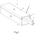
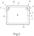
- a device 1 for receiving lines, cables 2 or current-conducting parts in an elongated cable duct 3 having a cable duct housing 7 is shown, which can be closed by means of a closure device 4 which can be connected to the cable duct housing 7.
- the cable duct housing 7 consists of at least two interconnected layers, with the first layer 5 surrounding the second layer 6 of the cable duct housing 7 at least on some sides or even completely.
- the lower side only needs to be provided with a second layer 6 in certain cases.
- the first layer 5 can be designed as an advertising medium or decorative layer. Therefore, it is advantageous according to the invention for the first layer 5 to be designed as a metal strip.
- the second layer 6, which surrounds the cable duct 3 of the cable duct housing 7, is made of plastic or at least partially elastic plastic and serves to accommodate cables or other elongated parts.
- the second layer 6 can also serve as an insulating layer.
- One part, in particular the upper part of the cable duct 3 7, is designed as a cover 9 which can be placed on the opening of the cable duct housing 7 and can be secured to the cable duct housing 7 by means of one or two locking devices 4 when, as previously mentioned, the cables have been laid in the cable duct housing 7.
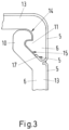
- the closure device 4 consists of a partially elastic hook 10 and an abutment 11, which can be firmly connected to each other.
- the hook is Fig. 3 formed onto an upright wall portion 13 and angled inward, or into the interior of the housing.
- the inclined portion of the hook forms a guide surface 15 against which the opposite side of a portion of the abutment 11 can rest when the cover 9 is placed on the cable duct housing 7.
- Both locking devices 4 are each provided in a corner area 12 of the cable duct housing 7.
- the cable duct housing 7 can be a round, oval, square, or polygonal housing, the wall parts 13 of which form a continuously flat, smooth surface 16 on all sides.
- the hook 10 and the abutment 11 are molded into the parts of the cable duct housing 7 in such a way that they do not protrude from the outer surface 16 of the wall parts 13 of the cable duct housing 7. This makes it easy to use all outer surfaces as decorative surfaces.
Landscapes
- Engineering & Computer Science (AREA)
- Architecture (AREA)
- Civil Engineering (AREA)
- Structural Engineering (AREA)
- Details Of Indoor Wiring (AREA)
- Installation Of Indoor Wiring (AREA)
Claims (5)
- Dispositif (1) pour la réception de lignes, de câbles (2) ou de pièces conductrices de courant, comprenant un canal de câbles (3) allongé, présentant un boîtier de canal de câbles (7), qui peut être fermé à l'aide d'un appareil de fermeture (4) qui peut être relié au boîtier de canal de câbles (7), le dispositif (1) présentant les caractéristiques suivantes :a) la partie supérieure du canal de câbles (3) est réalisée sous forme de couvercle (9) et est placée sur une ouverture du boîtier du canal de câbles (7) et peut être sécurisée au boîtier de canal de câbles (7) à l'aide de l'appareil de fermeture (4) ;b) le boîtier de canal de câbles est constitué d'au moins deux couches (5, 6) reliées entre elles ;c) une première couche (5) est une couche extérieure ;d) une deuxième couche (6) est une couche sous-jacente à la première couche (5) ;e) la première couche (5) entoure la deuxième couche (6) du boîtier de canal de câbles (7) ;f) une extrémité (17) de la première couche (5) est sécurisée pour ne pas se soulever et est placée entre une surface d'un contre-appui (11) prévu sur le couvercle (9) et une surface opposée d'un crochet (10) ;g) la première couche (5) entoure entièrement ou au moins sur certains côtés la deuxième couche (6) du boîtier de canal de câbles (7) ;h) le boîtier de canal de câbles (7) est réalisé sous forme de boîtier quadrangulaire ou polygonal dont les parties de paroi (13) forment de tous côtés une surface (16) lisse plate continue, le crochet (10) et le contre-appui (11) étant formés dans les parties du canal de câbles (3) de telle sorte qu'ils ne dépassent pas sur une surface extérieure (16) des parties de paroi (13) du boîtier de canal de câbles (7), la première couche (5) étant réalisée sous forme de couche décorative, la deuxième couche (6) étant réalisée sous forme de couche entourant le canal de câbles (3) du boîtier de canal de câbles (7), en matière plastique ou en matière plastique au moins partiellement élastique, caractérisé en ce que la première couche (5) est réalisée sous forme de bande métallique.
- Dispositif selon la revendication 1, caractérisé en ce que le crochet (10) est réalisé sous forme partiellement élastique, une partie de l'appareil de fermeture (4) étant fixée au couvercle (9) et l'autre partie étant fixée au boîtier de canal de câbles (7) ou formée sur celui-ci.
- Dispositif selon l'une quelconque des revendications 1 ou 2, caractérisé en ce que le pied ou le point de raccordement du crochet (10) sur une partie de paroi (13) du boîtier de canal de câbles (7) est réalisé sous forme élastique, sous forme de point articulé ou sous forme réglable de telle manière que, lors de la fermeture du couvercle (9) sur le boîtier de canal de câbles (7), une partie du crochet (10) est légèrement repliée en arrière en s'appuyant sur une surface de guidage (15) inclinée et est guidée le long de celle-ci jusqu'à ce qu'elle soit introduite derrière la surface de guidage (15) à l'aide de sa force de ressort dans un évidement (14) et pressée contre le contre-appui et sécurise ainsi le couvercle (9) sur le boîtier de canal de câbles (7).
- Dispositif selon l'une quelconque des revendications précédentes, caractérisé en ce que les appareils de fermeture (4) sont prévus chacun dans une zone de coin (12) du boîtier de canal de câbles (7).
- Dispositif selon l'une quelconque des revendications précédentes, caractérisé en ce qu'une extrémité (17) de la première couche ou de la bande métallique (5) enveloppe l'extrémité du contre-appui (11), et ce entre la surface de guidage (15) du contre-appui (11) et la surface opposée du crochet (10).
Priority Applications (2)
| Application Number | Priority Date | Filing Date | Title |
|---|---|---|---|
| EP18173948.3A EP3573201B1 (fr) | 2018-05-24 | 2018-05-24 | Dispositif pour recevoir des lignes; cables ou pièces conductrices electriquement |
| ES18173948T ES3041965T3 (en) | 2018-05-24 | 2018-05-24 | Device for receiving circuits; cables or electrically conducting parts |
Applications Claiming Priority (1)
| Application Number | Priority Date | Filing Date | Title |
|---|---|---|---|
| EP18173948.3A EP3573201B1 (fr) | 2018-05-24 | 2018-05-24 | Dispositif pour recevoir des lignes; cables ou pièces conductrices electriquement |
Publications (3)
| Publication Number | Publication Date |
|---|---|
| EP3573201A1 EP3573201A1 (fr) | 2019-11-27 |
| EP3573201C0 EP3573201C0 (fr) | 2025-07-02 |
| EP3573201B1 true EP3573201B1 (fr) | 2025-07-02 |
Family
ID=62245189
Family Applications (1)
| Application Number | Title | Priority Date | Filing Date |
|---|---|---|---|
| EP18173948.3A Active EP3573201B1 (fr) | 2018-05-24 | 2018-05-24 | Dispositif pour recevoir des lignes; cables ou pièces conductrices electriquement |
Country Status (2)
| Country | Link |
|---|---|
| EP (1) | EP3573201B1 (fr) |
| ES (1) | ES3041965T3 (fr) |
Family Cites Families (6)
| Publication number | Priority date | Publication date | Assignee | Title |
|---|---|---|---|---|
| US4258515A (en) * | 1977-09-13 | 1981-03-31 | Owen William J | Conduit trunking |
| GB2307111B (en) * | 1995-11-11 | 1997-09-10 | Caradon Mk Electric Ltd | Improvements to electrical trunking |
| GB2362270B (en) * | 2000-05-10 | 2002-05-29 | Caradon Mk Electric Ltd | Improvements in and relating to electrical trunking |
| DE10056441B4 (de) * | 2000-11-14 | 2004-02-12 | Rehau Ag + Co. | Kabelkanal und Verfahren zu seiner Herstellung |
| DE20021565U1 (de) * | 2000-12-21 | 2001-06-13 | Extruplast GmbH, 77746 Schutterwald | Kabelkanal |
| US10103528B2 (en) | 2016-06-30 | 2018-10-16 | Hellermanntyton Corporation | Cable duct |
-
2018
- 2018-05-24 ES ES18173948T patent/ES3041965T3/es active Active
- 2018-05-24 EP EP18173948.3A patent/EP3573201B1/fr active Active
Also Published As
| Publication number | Publication date |
|---|---|
| EP3573201C0 (fr) | 2025-07-02 |
| EP3573201A1 (fr) | 2019-11-27 |
| ES3041965T3 (en) | 2025-11-17 |
Similar Documents
| Publication | Publication Date | Title |
|---|---|---|
| EP1606867B1 (fr) | Dispositif de traversee de cable | |
| DE4233472C2 (de) | Deckel für eine Öffnung in einem Blech | |
| DE2145453A1 (de) | Tisch mit einer Anordnung zum Aufnehmen von Geräteanschlußkabeln | |
| DE3445935C2 (fr) | ||
| DE3430756C2 (fr) | ||
| DE102014016682A1 (de) | Elektronisches Installationsgerät | |
| DE3001574C2 (de) | Verfahren zur Montage elektrischer Installationsgeräte in vorgefertigten Hohlwänden und nach diesem Verfahren montierbare Einbaudose | |
| DE2748872C2 (de) | Gehäuse mit Schaltungsplatine für Koaxialkabel | |
| DE202016004646U1 (de) | Elektrisches Installationsgerät | |
| DE102010033648B4 (de) | Anordnung aus einem Behältnis zur Aufnahme von elektrischen Steckdosenleisten und einem Deckel | |
| EP0114918A2 (fr) | Cable protection device | |
| DE202007006989U1 (de) | Schnittkaschierung für Kabelkanäle | |
| DE102012217815B4 (de) | Leitungskanal | |
| DE202004014562U1 (de) | Gehäuse für Steckverbinder | |
| EP2282386B1 (fr) | Canal de plinthes doté d'un habillage d'arête | |
| DE3023974A1 (de) | Profilschiene zum aufhaengen von geraeten | |
| EP3573201A1 (fr) | Dispositif pour recevoir des lignes; cables ou pièces conductrices electriquement | |
| DE102012016597B3 (de) | Vorrichtung zur Befestigung mindestens einer elektrischen Leitung in einer Wandöffnung | |
| DE4217906C2 (de) | Kabeleinführungstülle zum Einführen eines Kabels in ein Gehäuse oder dergleichen | |
| AT405999B (de) | Gehäuse | |
| DE6810729U (de) | Stromleistensystem | |
| CH672563A5 (fr) | ||
| DE8814890U1 (de) | Wasserdichtes Gehäuse, insbesondere für die Verkapselung elektrischer und elektronischer Bauteile | |
| DE102016120021A1 (de) | Kabeldurchführung für Tischplatten | |
| DE10047715A1 (de) | Kabeldurchführung |
Legal Events
| Date | Code | Title | Description |
|---|---|---|---|
| PUAI | Public reference made under article 153(3) epc to a published international application that has entered the european phase |
Free format text: ORIGINAL CODE: 0009012 |
|
| STAA | Information on the status of an ep patent application or granted ep patent |
Free format text: STATUS: THE APPLICATION HAS BEEN PUBLISHED |
|
| AK | Designated contracting states |
Kind code of ref document: A1 Designated state(s): AL AT BE BG CH CY CZ DE DK EE ES FI FR GB GR HR HU IE IS IT LI LT LU LV MC MK MT NL NO PL PT RO RS SE SI SK SM TR |
|
| AX | Request for extension of the european patent |
Extension state: BA ME |
|
| STAA | Information on the status of an ep patent application or granted ep patent |
Free format text: STATUS: REQUEST FOR EXAMINATION WAS MADE |
|
| 17P | Request for examination filed |
Effective date: 20191209 |
|
| STAA | Information on the status of an ep patent application or granted ep patent |
Free format text: STATUS: EXAMINATION IS IN PROGRESS |
|
| 17Q | First examination report despatched |
Effective date: 20200204 |
|
| RBV | Designated contracting states (corrected) |
Designated state(s): AL AT BE BG CH CY CZ DE DK EE ES FI FR GB GR HR HU IE IS IT LI LT LU LV MC MK MT NL NO PL PT RO RS SE SI SK SM TR |
|
| GRAP | Despatch of communication of intention to grant a patent |
Free format text: ORIGINAL CODE: EPIDOSNIGR1 |
|
| STAA | Information on the status of an ep patent application or granted ep patent |
Free format text: STATUS: GRANT OF PATENT IS INTENDED |
|
| INTG | Intention to grant announced |
Effective date: 20250131 |
|
| GRAS | Grant fee paid |
Free format text: ORIGINAL CODE: EPIDOSNIGR3 |
|
| GRAA | (expected) grant |
Free format text: ORIGINAL CODE: 0009210 |
|
| STAA | Information on the status of an ep patent application or granted ep patent |
Free format text: STATUS: THE PATENT HAS BEEN GRANTED |
|
| AK | Designated contracting states |
Kind code of ref document: B1 Designated state(s): AL AT BE BG CH CY CZ DE DK EE ES FI FR GB GR HR HU IE IS IT LI LT LU LV MC MK MT NL NO PL PT RO RS SE SI SK SM TR |
|
| REG | Reference to a national code |
Ref country code: GB Ref legal event code: FG4D Free format text: NOT ENGLISH |
|
| REG | Reference to a national code |
Ref country code: CH Ref legal event code: EP |
|
| REG | Reference to a national code |
Ref country code: DE Ref legal event code: R096 Ref document number: 502018015918 Country of ref document: DE |
|
| REG | Reference to a national code |
Ref country code: IE Ref legal event code: FG4D Free format text: LANGUAGE OF EP DOCUMENT: GERMAN |
|
| U01 | Request for unitary effect filed |
Effective date: 20250731 |
|
| U07 | Unitary effect registered |
Designated state(s): AT BE BG DE DK EE FI FR IT LT LU LV MT NL PT RO SE SI Effective date: 20250808 |
|
| REG | Reference to a national code |
Ref country code: ES Ref legal event code: FG2A Ref document number: 3041965 Country of ref document: ES Kind code of ref document: T3 Effective date: 20251117 |
|
| PG25 | Lapsed in a contracting state [announced via postgrant information from national office to epo] |
Ref country code: IS Free format text: LAPSE BECAUSE OF FAILURE TO SUBMIT A TRANSLATION OF THE DESCRIPTION OR TO PAY THE FEE WITHIN THE PRESCRIBED TIME-LIMIT Effective date: 20251102 |
|
| PG25 | Lapsed in a contracting state [announced via postgrant information from national office to epo] |
Ref country code: NO Free format text: LAPSE BECAUSE OF FAILURE TO SUBMIT A TRANSLATION OF THE DESCRIPTION OR TO PAY THE FEE WITHIN THE PRESCRIBED TIME-LIMIT Effective date: 20251002 |
|
| PG25 | Lapsed in a contracting state [announced via postgrant information from national office to epo] |
Ref country code: HR Free format text: LAPSE BECAUSE OF FAILURE TO SUBMIT A TRANSLATION OF THE DESCRIPTION OR TO PAY THE FEE WITHIN THE PRESCRIBED TIME-LIMIT Effective date: 20250702 |
|
| PG25 | Lapsed in a contracting state [announced via postgrant information from national office to epo] |
Ref country code: GR Free format text: LAPSE BECAUSE OF FAILURE TO SUBMIT A TRANSLATION OF THE DESCRIPTION OR TO PAY THE FEE WITHIN THE PRESCRIBED TIME-LIMIT Effective date: 20251003 |
|
| PG25 | Lapsed in a contracting state [announced via postgrant information from national office to epo] |
Ref country code: CZ Free format text: LAPSE BECAUSE OF FAILURE TO SUBMIT A TRANSLATION OF THE DESCRIPTION OR TO PAY THE FEE WITHIN THE PRESCRIBED TIME-LIMIT Effective date: 20250702 |
|
| PG25 | Lapsed in a contracting state [announced via postgrant information from national office to epo] |
Ref country code: RS Free format text: LAPSE BECAUSE OF FAILURE TO SUBMIT A TRANSLATION OF THE DESCRIPTION OR TO PAY THE FEE WITHIN THE PRESCRIBED TIME-LIMIT Effective date: 20251002 |
|
| PG25 | Lapsed in a contracting state [announced via postgrant information from national office to epo] |
Ref country code: SM Free format text: LAPSE BECAUSE OF FAILURE TO SUBMIT A TRANSLATION OF THE DESCRIPTION OR TO PAY THE FEE WITHIN THE PRESCRIBED TIME-LIMIT Effective date: 20250702 |
|
| PG25 | Lapsed in a contracting state [announced via postgrant information from national office to epo] |
Ref country code: SK Free format text: LAPSE BECAUSE OF FAILURE TO SUBMIT A TRANSLATION OF THE DESCRIPTION OR TO PAY THE FEE WITHIN THE PRESCRIBED TIME-LIMIT Effective date: 20250702 |
|
| PLBE | No opposition filed within time limit |
Free format text: ORIGINAL CODE: 0009261 |
|
| STAA | Information on the status of an ep patent application or granted ep patent |
Free format text: STATUS: NO OPPOSITION FILED WITHIN TIME LIMIT |