EP3573208B1 - Circuit de commande de puissance et procédé de stabilisation d'une alimentation électrique - Google Patents
Circuit de commande de puissance et procédé de stabilisation d'une alimentation électrique Download PDFInfo
- Publication number
- EP3573208B1 EP3573208B1 EP19181726.1A EP19181726A EP3573208B1 EP 3573208 B1 EP3573208 B1 EP 3573208B1 EP 19181726 A EP19181726 A EP 19181726A EP 3573208 B1 EP3573208 B1 EP 3573208B1
- Authority
- EP
- European Patent Office
- Prior art keywords
- power
- mains
- frequency
- voltage
- load
- Prior art date
- Legal status (The legal status is an assumption and is not a legal conclusion. Google has not performed a legal analysis and makes no representation as to the accuracy of the status listed.)
- Active
Links
Images






Classifications
-
- H—ELECTRICITY
- H02—GENERATION; CONVERSION OR DISTRIBUTION OF ELECTRIC POWER
- H02J—ELECTRIC POWER NETWORKS; CIRCUIT ARRANGEMENTS OR SYSTEMS FOR SUPPLYING OR DISTRIBUTING ELECTRIC POWER; SYSTEMS FOR STORING ELECTRIC ENERGY
- H02J3/00—Circuit arrangements for AC mains or AC distribution networks
- H02J3/18—Arrangements for adjusting, eliminating or compensating reactive power in networks
-
- H—ELECTRICITY
- H02—GENERATION; CONVERSION OR DISTRIBUTION OF ELECTRIC POWER
- H02J—ELECTRIC POWER NETWORKS; CIRCUIT ARRANGEMENTS OR SYSTEMS FOR SUPPLYING OR DISTRIBUTING ELECTRIC POWER; SYSTEMS FOR STORING ELECTRIC ENERGY
- H02J3/00—Circuit arrangements for AC mains or AC distribution networks
- H02J3/001—Arrangements for handling faults or abnormalities, e.g. emergencies or contingencies
- H02J3/0014—Arrangements for handling faults or abnormalities, e.g. emergencies or contingencies for preventing or reducing power oscillations in networks
- H02J3/00142—Oscillations concerning frequency
-
- H—ELECTRICITY
- H02—GENERATION; CONVERSION OR DISTRIBUTION OF ELECTRIC POWER
- H02J—ELECTRIC POWER NETWORKS; CIRCUIT ARRANGEMENTS OR SYSTEMS FOR SUPPLYING OR DISTRIBUTING ELECTRIC POWER; SYSTEMS FOR STORING ELECTRIC ENERGY
- H02J3/00—Circuit arrangements for AC mains or AC distribution networks
- H02J3/12—Arrangements for adjusting voltage in AC networks by changing a characteristic of the network load
-
- H—ELECTRICITY
- H02—GENERATION; CONVERSION OR DISTRIBUTION OF ELECTRIC POWER
- H02J—ELECTRIC POWER NETWORKS; CIRCUIT ARRANGEMENTS OR SYSTEMS FOR SUPPLYING OR DISTRIBUTING ELECTRIC POWER; SYSTEMS FOR STORING ELECTRIC ENERGY
- H02J3/00—Circuit arrangements for AC mains or AC distribution networks
- H02J3/12—Arrangements for adjusting voltage in AC networks by changing a characteristic of the network load
- H02J3/16—Arrangements for adjusting voltage in AC networks by changing a characteristic of the network load by adjustment of reactive power
-
- H—ELECTRICITY
- H02—GENERATION; CONVERSION OR DISTRIBUTION OF ELECTRIC POWER
- H02J—ELECTRIC POWER NETWORKS; CIRCUIT ARRANGEMENTS OR SYSTEMS FOR SUPPLYING OR DISTRIBUTING ELECTRIC POWER; SYSTEMS FOR STORING ELECTRIC ENERGY
- H02J3/00—Circuit arrangements for AC mains or AC distribution networks
- H02J3/18—Arrangements for adjusting, eliminating or compensating reactive power in networks
- H02J3/1807—Arrangements for adjusting, eliminating or compensating reactive power in networks using series compensators, e.g. thyristor-controlled series capacitors [TCSC]
- H02J3/1814—Arrangements for adjusting, eliminating or compensating reactive power in networks using series compensators, e.g. thyristor-controlled series capacitors [TCSC] having reactive elements actively controlled by bridge converters, e.g. unified power flow controllers [UPFC] or controlled series voltage compensators
-
- H—ELECTRICITY
- H02—GENERATION; CONVERSION OR DISTRIBUTION OF ELECTRIC POWER
- H02J—ELECTRIC POWER NETWORKS; CIRCUIT ARRANGEMENTS OR SYSTEMS FOR SUPPLYING OR DISTRIBUTING ELECTRIC POWER; SYSTEMS FOR STORING ELECTRIC ENERGY
- H02J3/00—Circuit arrangements for AC mains or AC distribution networks
- H02J3/18—Arrangements for adjusting, eliminating or compensating reactive power in networks
- H02J3/1821—Arrangements for adjusting, eliminating or compensating reactive power in networks using shunt compensators
- H02J3/1835—Arrangements for adjusting, eliminating or compensating reactive power in networks using shunt compensators with stepless control
- H02J3/1842—Arrangements for adjusting, eliminating or compensating reactive power in networks using shunt compensators with stepless control having reactive elements actively controlled by bridge converters, e.g. active filters or static compensators [STATCOM]
-
- Y—GENERAL TAGGING OF NEW TECHNOLOGICAL DEVELOPMENTS; GENERAL TAGGING OF CROSS-SECTIONAL TECHNOLOGIES SPANNING OVER SEVERAL SECTIONS OF THE IPC; TECHNICAL SUBJECTS COVERED BY FORMER USPC CROSS-REFERENCE ART COLLECTIONS [XRACs] AND DIGESTS
- Y02—TECHNOLOGIES OR APPLICATIONS FOR MITIGATION OR ADAPTATION AGAINST CLIMATE CHANGE
- Y02E—REDUCTION OF GREENHOUSE GAS [GHG] EMISSIONS, RELATED TO ENERGY GENERATION, TRANSMISSION OR DISTRIBUTION
- Y02E40/00—Technologies for an efficient electrical power generation, transmission or distribution
- Y02E40/10—Flexible AC transmission systems [FACTS]
-
- Y—GENERAL TAGGING OF NEW TECHNOLOGICAL DEVELOPMENTS; GENERAL TAGGING OF CROSS-SECTIONAL TECHNOLOGIES SPANNING OVER SEVERAL SECTIONS OF THE IPC; TECHNICAL SUBJECTS COVERED BY FORMER USPC CROSS-REFERENCE ART COLLECTIONS [XRACs] AND DIGESTS
- Y02—TECHNOLOGIES OR APPLICATIONS FOR MITIGATION OR ADAPTATION AGAINST CLIMATE CHANGE
- Y02E—REDUCTION OF GREENHOUSE GAS [GHG] EMISSIONS, RELATED TO ENERGY GENERATION, TRANSMISSION OR DISTRIBUTION
- Y02E40/00—Technologies for an efficient electrical power generation, transmission or distribution
- Y02E40/20—Active power filtering [APF]
-
- Y—GENERAL TAGGING OF NEW TECHNOLOGICAL DEVELOPMENTS; GENERAL TAGGING OF CROSS-SECTIONAL TECHNOLOGIES SPANNING OVER SEVERAL SECTIONS OF THE IPC; TECHNICAL SUBJECTS COVERED BY FORMER USPC CROSS-REFERENCE ART COLLECTIONS [XRACs] AND DIGESTS
- Y02—TECHNOLOGIES OR APPLICATIONS FOR MITIGATION OR ADAPTATION AGAINST CLIMATE CHANGE
- Y02E—REDUCTION OF GREENHOUSE GAS [GHG] EMISSIONS, RELATED TO ENERGY GENERATION, TRANSMISSION OR DISTRIBUTION
- Y02E40/00—Technologies for an efficient electrical power generation, transmission or distribution
- Y02E40/30—Reactive power compensation
Definitions
- the present invention relates to power control circuits and methods for stabilizing power supplies, and in particular, but not limited to, circuits and methods of this type that are used with distributed loads connected to a dynamically changing power supply, such as that generated by dynamically changing renewable energy sources.
- reactive power controllers also known as reactive power compensators
- reactive power controllers have been well-researched as a tool to provide voltage stability in power transmission lines as early as 1982, as shown in T.J. Miller, "Reactive Power Control in Electric Systems", John Wiley & Sons, 1982 .
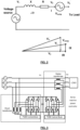
- the basic concept of using reactive power for voltage stability control can be illustrated in Fig.1a , in which the equivalent circuit and its vector diagram for an ac mains voltage and the transmission line impedance are shown. It can be seen from the vector diagram that the output voltage V 2 is reduced because of the transmission line resistance and impedance.
- the active (which is also known as “real”) and reactive (which is also known as “imaginary”) source current are labelled as I P and I Q , respectively.
- the active current I P is in phase with V 2 and will contribute to real power consumption in the load.
- the reactive current I Q is 90° out of phase (lagging behind) V 2 and will not contribute to real power dissipation. Therefore, the power associated with I Q is called reactive power because it flows into and out of the system without being dissipated.
- a reactive current (and its associated reactive power) is injected into the system as shown in Fig.1b , the voltage drop due to the reactive current I Q can be compensated by the injected current I Q ' .
- the output V 2 can be increased or boosted because its voltage drop can be reduced.
- I Q ' is in phase with I Q' V 2 can be reduced.
- the line voltage V 2 can be adjusted depending on how the reactive power is injected into the system.
- Fig.1b demonstrates the basic concept of shunt reactive power compensation that can be used to stabilise the voltage in a power line. Shunt compensation is also known as parallel compensation because the reactive power source is placed in parallel with the load.
- Reactive power compensation can also be done in a series manner. If an auxiliary or compensating voltage source V comp with its voltage vector being perpendicular to the current I is created and is placed in series with the load as shown in Fig.2 , the vector diagram shows that the output V 2 can be controlled. It should be noted that V comp can be 90° (assisting) of 270° (opposing) out of phase with I. This means V 2 can be increased or decreased to V 2 ' as shown in Fig.2 .
- the scheme in Fig.2 is known as series reactive power compensation because the reactive power source is placed in series with the load.
- the series and shunt reactive power compensators can be used individually or together.
- a unified power flow controller (UPFC) is formed when a series and a shunt reactive power controller are used together as shown in Fig.3 .
- the two reactive power controllers share a common dc power supply created by the capacitor.
- the anti-parallel diodes of the two inverters form two natural diode rectifiers that connect the ac power line voltages to the dc capacitor. Consequently, the capacitor can be charged up and used as a dc voltage source.
- the switching actions of the two inverters can be sinusoidally pulsed-width modulated so that their filtered PWM voltage waveforms are sinusoidal ( Fig.4 ).
- the magnitude of the output voltage can be controlled by the modulation index and the phase can also be controlled with respect to the current.
- the reactive power of the series and shunt compensators is injected through the isolation transformers into the power lines.
- the reactive power controller can be practically realized with the use of a power inverter and an energy storage element, which can be either a large capacitor acting as a voltage source or an inductor acting as a current source as shown in Fig.5 .
- the inverters are not restricted to two-level inverters shown in Fig.3 , Fig.4 and Fig.5 .
- Multi-level inverters can in principle be used to generate the ac voltage waveforms. If multi-level inverters are used, the filtering efforts can be reduced at the expense of increased numbers of switches and circuit and control complexity.
- reactive power controllers can be used to absorb or deliver reactive power.
- reactive power compensators are used for medium to high power applications from hundreds of kilo-Volt-Amperes (kVA) to thousands of kVA.
- kVA kilo-Volt-Amperes
- UPFCs high power transmission lines.
- UPFCs heavy-current applications such as welding facilities, which draw large and non-linear currents that deteriorate the power quality of the power source.
- auxiliary voltage Va using a "series" reactive power controller (shown in the dotted box) in Fig.6 so that the output voltage of the controller Vo can be adjusted from the mains voltage Vs (typically 220V to 240V) down to a minimum voltage of 180V, which is the guaranteed minimum voltage for normal lighting system operation suggested by the manufacturers.
- the dimming level (or the value of the output voltage) is set by a dimming command signal as shown in Fig.6 and is kept constant at the controlled voltage level so as to keep the light intensity of the lighting system stable.
- patent GB2418786 also suggests the use of an extra shunt reactive power controller as a power factor correction circuit.
- This concept is a modified use of the UPFC in Fig.3 , but its application is for the function of dimming (using a series reactive power controller) and power factor correction (using a shunt reactive power controller).
- the circuit proposed in Fig.7 is not intended to be used for power stability as a UPFC is used for very high power systems.
- the reactive power controllers in patents GB2405540.B and GB2418786 are used to reduce the output voltage Vo, which has to be less than or equal to the input mains voltage Vs.
- known reactive power controllers are concerned with controlling the output voltage, or Vo as referred to above, of the reactive power controller which is being supplied to the load.
- the controlled variable is the output voltage (or Vo as referred to above) of the series reactive power controller.
- the controllable loads are in particular an electric water heater (EWH) and a battery. The effectiveness of such systems is discussed by simulating their behavior.
- EWH electric water heater
- a power control circuit 1 connectable to a load 2 adapted to receive a power supply 3.
- the power control circuit 1 is adapted to absorb power from the power supply 3 and adapted to deliver power to the power supply 3 tostabilize at least one electrical parameter of the power supply 3.
- the power absorbed and delivered by the power control circuit 1 includes reactive power, or active power, or both.
- the power control circuit 1 is further adapted to deliver powerto the load 2 to stabilize the at least one electrical parameter of the power supply 3.
- the power control circuit 1 maintains the power supply 3at a nominal supply voltage Vs.
- This nominal supply voltage can be any of the nominal mains voltages provided by power grids in various countries.
- the nominal supply voltage can be 110V, 220V, 230V, or 240V.
- the load 2 has a load voltage Vo and the power control circuit 1 provides an auxiliary voltage Va such that the vectorial sum of the load and auxiliary voltages equal the nominal supply voltage Vs.
- the load 2 has a load current Io and the auxiliary voltage Va isat a phase angle perpendicular to the load current Io.
- the at least one electrical parameter is frequency, with the power control circuit 1 maintaining the power supply 3 at a nominal supply frequency.
- This nominal supply frequency can be any of the nominal mains frequencies provided by power grids in various countries.
- the nominal supply frequency can be 50Hz or 60Hz.
- the load 2 has a load voltage Vo and the power control circuit 1 can decrease the load voltage when the frequency of the power supply is lower than the nominal supply frequency.
- the power control circuit 1 can also increase the load voltage Vo when the frequency of the power supply is higher than the nominal supply frequency.
- the load voltage Vo is increased to exceed a nominal supply voltage Vs. This can be done by having the power control circuit 1 provide an auxiliary voltage Va to increase or decrease the load voltage Vo.
- the power control circuit 1 stabilizes both the electrical parameters of voltage and frequency of the power supply 3, with the power control circuit 1 maintaining the power supply 3 at a nominal supply voltage Vs, and maintaining the power supply 3 at a nominal supply frequency, as described above.
- the power control circuit 1 includes a power controller 4 for absorbing and delivering power thereby enabling the power control circuit 1 to absorb and deliver power.
- the power controller 4 can absorb and deliver reactive power, or active power, or both.
- the power controller 4 is a reactive power controller.
- the present disclosure proposes the methodology of using (1) the reactive power of the reactive power controller and/or (2) the active power control of the loads as a new generation of "smart loads" that serve the dual purposes of maintaining power grid stability and controlling the power consumptions of the loads.
- the proposed smart load methodology involves both (1) the control of reactive power of the reactive power controller and (2) control of the active power consumption of the loads.
- the reactive power controller 4 can be designed as a separate unit to the load 2 or it can be designed with the load in an integrated manner. It can be used for both electric loads with variable power consumption and also for loads with constant power, depending on the configurations of the reactive power controllers.
- smart loads based on examples of the present disclosure can be installed all over smart grids and provide stabilising effects (or cushioning effects) to power lines over the smart grids.
- the proposed methodology of the disclosure can be adopted in domestic water heaters and road lighting systems, which are distributed all over cities by the nature of their mode of installation.
- a reactive power controller can absorb and deliver reactive energy so it can effectively vary (decrease and increase) the power line voltage.
- a reactive power controller can absorb and deliver reactive energy so it can effectively vary (decrease and increase) the power line voltage.
- a reactive power controller 4 is proposed to be used as an "electric spring” or “voltage stabiliser” to keep stable the voltage of the power lines to which this reactive power controller is connected.
- the ability of the reactive power controller to absorb and deliver reactive power can be used to maintain voltage stability. Since the reactive power controllers are connected with the electric loads to form “smart loads", which are distributed for example over cities or other power grids, the installations of the proposed smart loads will provide many local “electric springs” or “voltage stabilisers” distributed all over the cities or the power grids to form “smart grids”. They can therefore provide voltage stabilisation and damping of oscillations over the power grids.
- Such distributed voltage support over a large power network of smart grids is similar to the distributed mechanical support provided by the springs of a mattress as shown in Fig.9 .
- the control loop of the reactive power controller will be much different from that used in GB2405540.B and GB2418786 , which are proposed not for power grid voltage stabilization, but for the dimming of lighting systems only.
- the smart load with the series reactive power controller structure is now explained with the aid of Fig.11 .
- the loads here could be any electric loads that do not require constant power.
- Application examples are domestic and industrial water heaters, individual lighting system or preferably a network of lighting systems for public areas, and some electrical appliances that can tolerate a wider fluctuation of supply voltage that exceeds the nominal tolerance. These are also known as "non-critical" loads.
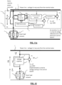
- Fig.11a shows the schematic of a series-type smart load control method (i.e. Structure-1 of Fig.10 ).
- the new control method of examples of the present disclosure uses the nominal mains voltage, also called the nominal supply voltage, Vs_ref as a reference.
- Vs_ref the nominal supply voltage
- the voltage reference of this control method Vs_ref could be set in the electronic control board of the control system as equivalent to 230V.
- This voltage reference representing 230V is implemented as a constant voltage in the control board of a power controller in accordance with an example of the present disclosure.
- the switch S is a bypass switch, which when closed, allows power to bypass the series reactive power controller and connects the load directly to the power lines without reactive power control.
- Fig. 1 1b shows a similar schematic which includes a network of loads, instead of a single load.
- the difference between the actual ac mains voltage Vs and the reference mains voltage is fed to a voltage controller 5, which can be any suitable controller such as a proportional-integral (PI) controller or a lead-lag compensator.
- the output of the voltage controller 5 provides a control signal for the Pulse-Width-Modulated (PWM) Generator 6.
- a synchronization network 7 is used to provide the phase information for the PWM Generator 6, which generates the switching signals for the power semiconductor switches of a power inverter 8 to generate a high-voltage sinusoidal PWM voltage waveform.
- the dc voltage of the power inverter 8 is usually obtained from a capacitor 9 which is charged through the anti-parallel diodes of the inverter switches (like a diode rectifier with an output dc capacitor).
- the PWM voltage generated by the power inverter 8 is filtered by a low-pass LC filter so that an auxiliary sinusoidal voltage Va can be created.
- the power inverter 8 (being used as part of a reactive power controller) will not consume active power in the process of creating the auxiliary voltage Va, assuming that the conduction loss, core loss and the switching loss of the power inverter circuit and filter are negligible.
- auxiliary voltage Va can be generated in either polarity, so that the series reactive power controller will cause the actual power line voltage Vs to follow its nominal reference value Vs ref
- the schematic proposed in Fig. 11 can be considered as an "electric spring” or “voltage stabiliser” as shown in Fig. 12 .
- FIG.11c An alternative control method for fast response of the series structure is shown in Fig.11c .
- the novel feature of having a series reactive power controller connected in series with the load, with the combined unit connected to the power lines remains the same as Figs.11a and 11b .
- this method includes a fast inner control loop based on the sensing of the dc voltage across the storage capacitor 9. Since the magnitude of the voltage Va generated by the PWM inverter 8 depends on the dc voltage Vdc, any variation of Vdc is a faster indication of the load demand response than the indication obtained from the variation of the rms value of Vs.
- Figs. 11a , 11b and 11c can be incorporated into shunt reactive power control to form an electric spring either (i) as an independent unit for turning an existing load into a smart load or (ii) as an integrated part of the load to form an integrated smart load.
- the setup consists of two sets of loads.
- the load network 2 connected in series to the series reactive power controller 4 is together called the "smart load network".
- These loads 10 represent other loads that are not under the control of examples of the present disclosure in the same power grid.
- the smart load network in the test includes resistors (representing water heaters) and some ballast driven light-emitting diode LED devices (representing road lighting systems).
- the first series of tests involve the generation of an unstable mains, or supply, voltage with a sinusoidal fluctuation. Due to this dynamically changing nature, the power flow is not constant and there are obvious fluctuations in the power line voltage as recorded in Figs. 14a-f .
- the measurements were captured initially with the "electric spring” (i.e. the series reactive power controller) turned off and the bypass switch S closed. Measurements were then captured with the “electric spring” (i.e. the reactive power controller 4) activated and the bypass switch S open.
- the rms voltage values of the power lines (Vs), the voltage across the smart load network and the voltage of the electric spring (Va) are plotted in Fig. 16a .
- the setup is designed to generate the same unstable voltage patterns in the mains twice by the simulated wind energy source.
- the bypass switch S is closed and the electric spring is deactivated.
- the voltage of the smart load network is therefore the same as the mains voltage which fluctuates below the nominal value of 220V in this test.
- the second half of the test the same unstable voltage from the simulated wind energy source is generated. It should be noted that there some points in the programmed voltage pattern where the generated mains voltage reaches or exceeds 220V in Fig. 16a .
- Fig. 16a it can be seen from the first half when the electric spring is turned off (i.e. bypass switch S is closed) that the voltage of the smart load network follows the unstable mains voltage pattern.
- the bypass switch S is opened and the electric spring is turned on in the second half with the same unstable voltage pattern from the wind energy source, the auxiliary voltage generated by the electric spring varies in such a dynamical manner that the mains voltage of the power lines is restored closely to the preset nominal value of 220V.
- the mains voltage vector of Vs is equal to the vectorial sum of voltage across the power controller 4, Va, and the voltage across the load 2, Vo. These are related in vectorial form as shown in Fig. 17 .
- Their values in Fig. 16a are scalar values. It is important to note that when the generated mains voltage reaches or exceeds 220V, the voltage of the electric spring drops to zero. This measurement confirms the dynamic functions of the electric spring in providing reactive power compensation to maintain voltage regulation dynamically.
- Fig. 16b The measurements of the measured mains voltage, the active power and the reactive power of the smart load network are recorded and displayed together in Fig. 16b . It can be seen that, after the electric spring is activated in the second half of the test, the patterns of the active power and reactive power of the smart load network change from their previous patterns. Generally, there is a reduction of active power (i.e. some form of load shedding) and an increase of reactive power in the smart load network.
- Structure-1 illustrates the unique feature that using a series reactive power controller in series with an electric load can turn the combined unit into a smart load which can (1) provide reactive power compensation for mains power supply voltage regulation and (2) enable the load demand to follow a dynamic power (e.g. renewable or wind power) profile.
- a series reactive power controller in series with an electric load can turn the combined unit into a smart load which can (1) provide reactive power compensation for mains power supply voltage regulation and (2) enable the load demand to follow a dynamic power (e.g. renewable or wind power) profile.
- the shunt-type structure in Fig. 10b will be more appropriate because the operation of the shunt reactive power controller serves to maintain good voltage regulation for the load without substantially affecting the active power consumption of the load.
- Equation (3) now provides the mathematical relationship between power generated and power consumed.
- the first term on the right hand side of (3) is the power consumed by the non-critical load and the second term is the power consumed by other loads.
- Vs in (3) is a constant.
- a reduction in wind power generation Pin leads to an increase of Va, and vice versa.
- An increase in Va, according to (1) results in a reduction in Vo, and therefore will decrease the load power according to (2). Therefore, these three equations provide the explanation for why the load demand will follow the wind power based on the proposed method.
- Fig.22 further illustrates this point while comparing the power profiles of non-critical and critical loads.
- series and shunt arrangements can be combined to form the series-shunt arrangements as shown in Fig. 10c and Fig.10d .
- Structure-3 of Fig. 10c can be realized in the form as shown in Fig. 18 . It should be noted that Structure-3 retains the novel feature that a series power controller 4 is connected in series, as a first power controller, with the load 2 and the combined unit is connected to the power lines 3.
- the power control circuit 1 of Structure-3 further includes a second power controller 4' connected in parallel across the series, or first, power controller 4 and the load 2.
- the second power controller 4' is also called a shunt power controller.
- Structure-3 offers other control function possibilities if the two power controllers are allowed to handle both active and reactive power. With the provision of a power transfer connection 11 between the shunt power controller 4' and the series power controller 4 (e.g.
- the power transfer connection 11 in the present example is a shared capacitor storage element as shown in the circuits in Figs. 18 , 19 and 20 . More particularly, the capacitor is connected in parallel across both the first and second power controllers 4 and 4'.
- An example of this operation is to use the series power controller 4 to absorb active power, which is then transferred back to the power line 3 by the shunt power controller 4' in order to avoid necessary power loss.
- the voltage vector of Va can be at any angle with respect with the current vector Io. In this way, the voltage vector of the mains voltage Vs can be changed with a smaller voltage vector of Va (when compared with Fig.17 ), allowing the voltage rating of the series controller 4 to be reduced.
- the adjustment of Vo means that the active power of the smart load can be controlled in this operating mode.
- the power control circuit 1 includes a second power controller 4', wherein the first power controller 4 is connected in series with the power supply 3 and the load 2, and the second power controller 4' (also known as a shunt power controller) is connected in parallel across the load 2.
- the series reactive power controller 4 is controlled in inductive mode and is simulated as an equivalent inductor with a series resistance.
- the shunt reactive power controller 4' is operated in capacitive mode and is thus represented as an equivalent capacitor with a small resistance. It will be appreciated that the power line voltage can be slightly boosted if necessary.
- these smart loads with voltage stabilizing ability will provide strong cushioning effects to reduce the voltage fluctuations of the power lines in large-scale smart grids, even when the dynamically changing nature of the power supply, due to for example the increasing amount of renewable energy sources, becomes increasingly influential in future smart grid systems.
- the smart load methodology with reactive power control capability essentially includes (1) reactive power compensation functions for voltage stability and (2) load power control.
- the demand response (load power) can now follow the power generation and play a supporting role in maintaining power line voltage stability, which is a unique feature required in future smart grids.
- the priority should and can be placed on security of the power grids. This means that loads may have to vary in order to maintain power grid stability.
- the smart load should react with the priority of maintaining voltage stability.
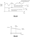
- Fig.22 illustrates the difference in power profiles between non-critical loads and critical loads, where the non-critical loads are controlled by power control circuits or power controllers of the present disclosure.
- the power of non-critical loads as controlled by power control circuits or power controllers of the present disclosure follows the dynamically changing power profile of the dynamically changing power supply, such as those based on renewable energy sources.
- some examples of the present disclosure are adapted to stabilize the frequency of the power supply.
- the frequency of the generators may deviate from the nominal values of 50Hz or 60Hz depending on the load demand. If the load demand exceeds the power generated, the frequency will be reduced slightly from the nominal value, and vice versa. Consequently, frequency instability might occur. This is shown schematically in Fig.23 .
- Structrue-3 as described above, can be used to improve the frequency instability problem by controlling the real power of the non-critical load 2 as illustrated in Fig.24 .
- a reliable frequency feedback is compared with a reference frequency (of the nominal mains frequency 50Hz or 60Hz).
- the frequency error can be fed to a frequency controller 12 which in turn control the first power controller 4 and the second power controller 4' such that:
- smart grids In summary, in emerging smart grid power systems (“smart grids”), it is expected that renewable energy sources (such as wind farms and solar photovoltaic plants) with dynamically changing power flow will be installed. Future smart grids will be different from existing power grids in which the power generation is well-controlled by the power stations. The foreseeable massive penetration of renewable energy sources that are often distributed in the power grids would likely cause power system instabilities (such as instability and oscillations in voltage and frequency).
- Particular examples of the present disclosure are related to the use of distributed reactive power controllers designed with or integrated with electric loads for improving the system voltage and frequency stability of smart power grid systems (smart grids), particularly those smart grids that have a significant portion of power coming from dynamically changing renewable energy sources such as wind and solar photovoltaic power plants.
- smart grids smart power grid systems
- Examples of the present disclosure include configurations that can be associated to electric loads with fairly high tolerance with wide variations in ac supply voltage such as lighting systems and heating systems, and also electric loads that require tight voltage regulations.
- the proposed smart electronic load of some examples of the disclosure has a reactive power controller connected in series with the loads.
- Examples are water heating systems used domestically and industrially and lighting systems used in public areas (e.g. streets and highways) and buildings in general.
- Examples of the present disclosure include a basic unit that consists of a reactive power controller being in series with a load. This basic unit (i.e. a series reactive power controller and the load) will then be connected across the power lines. This basic unit is different from the convention use of a static VAR compensator which is connected across the power lines. Shunt reactive power controllers can be added to this basic structure.
- known reactive power controllers are concerned with controlling the output voltage, or Vo as referred to above, of the reactive power controller which is being supplied to the load.
- the controlled variable is the output voltage (or Vo as referred to above) of the series reactive power controller.
Landscapes
- Engineering & Computer Science (AREA)
- Power Engineering (AREA)
- Supply And Distribution Of Alternating Current (AREA)
- Control Of Electrical Variables (AREA)
- Inverter Devices (AREA)
Claims (12)
- Circuit de commande de puissance (1) pouvant être connecté à une charge non critique (2) adaptée pour recevoir une alimentation secteur (3), le circuit de commande de puissance comprenant un dispositif de commande de puissance réactive en série (4) et un dispositif de commande de puissance réactive shunt (4') pour absorber et délivrer une puissance permettant ainsi au circuit de commande de puissance (1) d'absorber une puissance en provenance de l'alimentation secteur (3) et de délivrer une puissance à celle-ci afin de stabiliser une fréquence secteur de l'alimentation secteur (3), ladite puissance étant active, ledit circuit de commande de puissance (1) étant conçu pour maintenir l'alimentation secteur (3) à une fréquence secteur nominale, caractérisé en ce que le circuit de commande de puissance (1) est configuré de sorte qu'une différence entre une rétroaction de fréquence et une fréquence secteur de référence, qui est la fréquence secteur nominale, soit transmise à un dispositif de commande de fréquence (12), ledit dispositif de commande de fréquence (12) étant configuré pour commander le dispositif de commande de puissance réactive en série (4) et le dispositif de commande de puissance réactive shunt (4') pour diminuer une tension aux bornes de la charge si la fréquence secteur est inférieure à la fréquence secteur nominale et pour augmenter la tension aux bornes de la charge si la fréquence secteur est supérieure à la fréquence secteur nominale, ledit dispositif de commande de puissance réactive en série (4) étant connecté en série avec l'alimentation secteur (3) et la charge non critique (2), et ledit dispositif de commande de puissance réactive shunt (4') étant connecté en parallèle aux bornes du dispositif de commande de puissance réactive en série et de la charge non critique (2), et ledit dispositif de commande de puissance réactive en série (4) et ledit dispositif de commande de puissance réactive shunt étant interconnectés par l'intermédiaire d'une connexion de transfert de puissance, ladite connexion de transfert de puissance comprenant un élément de stockage d'énergie, et ledit élément de stockage d'énergie étant un condensateur connecté aux bornes à la fois du dispositif de commande de puissance réactive en série (4) et du dispositif de commande de puissance réactive shunt (4').
- Circuit de commande de puissance selon la revendication 1, ledit circuit de commande de puissance étant configuré pour augmenter la tension aux bornes de la charge (2) de façon à dépasser une tension secteur nominale.
- Circuit de commande de puissance (1) selon la revendication 1, ledit dispositif de commande de fréquence (12) étant configuré pour détecter la fréquence secteur de l'alimentation secteur (3) et pour fournir un signal de commande de fréquence sur la base que la fréquence secteur de l'alimentation secteur (3) est supérieure ou inférieure à la fréquence secteur nominale, ledit circuit de commande de puissance étant configuré pour se référer au signal de commande de fréquence pour absorber ou fournir une puissance lorsque la fréquence secteur de l'alimentation secteur (3) est supérieure ou inférieure à la fréquence secteur nominale, maintenant ainsi l'alimentation secteur (3) à la fréquence secteur nominale.
- Circuit de commande de puissance (1) selon la revendication 1, ladite charge non critique (2) étant un chauffe-eau ou une charge d'éclairage.
- Circuit de commande de puissance (1) selon la revendication 1, ledit circuit de commande de puissance (1) étant fourni d'un seul tenant avec la charge (2).
- Circuit de commande de puissance (1) selon la revendication 1, comprenant un circuit de dérivation comportant un commutateur de dérivation servant à connecter l'alimentation secteur (3) directement à la charge non critique (2) par l'intermédiaire du circuit de dérivation.
- Circuit de commande de puissance (1) selon la revendication 1, ladite alimentation secteur (3) comportant un profil de puissance changeant dynamiquement et ladite puissance de la charge non critique (2) suivant le profil de puissance changeant dynamiquement.
- Procédé de stabilisation d'une fréquence secteur d'une alimentation secteur (3) couplée électriquement à un circuit de commande de puissance (1), qui est connecté à une charge non critique (2), le procédé comprenant l'absorption de puissance en provenance de l'alimentation secteur (3) ou la fourniture de puissance à l'alimentation secteur (3) par le circuit de commande de puissance (1), ledit procédé comprenant l'absorption et la fourniture de puissance permettant ainsi au circuit de commande de puissance (1) d'absorber une puissance en provenance de l'alimentation secteur (3) et de délivrer une puissance à celle-ci afin de stabiliser la fréquence secteur de l'alimentation secteur (3), ladite puissance étant active, ladite alimentation secteur (3) étant maintenue à une fréquence secteur nominale, caractérisé en ce qu'une différence entre une rétroaction de fréquence et une fréquence secteur de référence, qui est la fréquence secteur nominale, est transmise à un dispositif de commande de fréquence (12), et une tension aux bornes de la charge non critique (2) est diminuée si la fréquence secteur de l'alimentation secteur (3) est inférieure à la fréquence secteur nominale et augmentée si la fréquence secteur de l'alimentation secteur (3) est supérieure à la fréquence secteur nominale, comprenant la fourniture d'un dispositif de commande de puissance réactive en série (4) et d'un dispositif de commande de puissance réactive shunt (4') pour absorber et fournir une puissance, ledit dispositif de commande de puissance réactive en série (4) étant connecté en série avec l'alimentation secteur (3) et la charge non critique (2), et
ledit dispositif de commande de puissance réactive shunt (4') étant connecté en parallèle aux bornes du dispositif de commande de puissance réactive en série (4) et de la charge non critique (2), lesdits dispositifs de commande de puissance (4, 4') étant interconnectés par l'intermédiaire d'une connexion de transfert de puissance (11), ladite connexion de transfert de puissance (11) comprenant un élément de stockage d'énergie, et ledit élément de stockage d'énergie étant un condensateur connecté en parallèle aux bornes des deux dispositifs de commande de puissance (4, 4'). - Procédé selon la revendication 8, ladite tension aux bornes de la charge (2) étant augmentée pour dépasser une tension secteur nominale.
- Procédé selon la revendication 8, comprenant la fourniture du dispositif de commande de fréquence (12) pour la détection de la fréquence secteur de l'alimentation secteur (3) et la fourniture d'un signal de commande de fréquence sur la base que la fréquence secteur de l'alimentation secteur (3) est supérieure ou inférieure à la fréquence d'alimentation secteur nominale, se référant au signal de commande de fréquence pour absorber ou délivrer une puissance lorsque la fréquence secteur de l'alimentation secteur (3) est supérieure ou inférieure à la fréquence d'alimentation secteur nominale, maintenant ainsi l'alimentation secteur (3) à la fréquence d'alimentation secteur nominale.
- Procédé selon la revendication 8, ledit circuit de commande de puissance (1) étant fourni d'un seul tenant avec la charge (2).
- Procédé selon la revendication 8, ladite alimentation secteur (3) comportant un profil de puissance changeant dynamiquement et ladite puissance étant absorbée en provenance de l'alimentation secteur (3) ou délivrée à l'alimentation secteur (3) de sorte que la puissance de la charge (2) suive le profil de puissance changeant dynamiquement.
Applications Claiming Priority (3)
| Application Number | Priority Date | Filing Date | Title |
|---|---|---|---|
| US38948910P | 2010-10-04 | 2010-10-04 | |
| EP11830187.8A EP2625759B1 (fr) | 2010-10-04 | 2011-09-30 | Circuit de commande électrique et procédé de stabilisation d'une alimentation électrique |
| PCT/CN2011/001667 WO2012045231A1 (fr) | 2010-10-04 | 2011-09-30 | Circuit de commande électrique et procédé de stabilisation d'une alimentation électrique |
Related Parent Applications (2)
| Application Number | Title | Priority Date | Filing Date |
|---|---|---|---|
| EP11830187.8A Division EP2625759B1 (fr) | 2010-10-04 | 2011-09-30 | Circuit de commande électrique et procédé de stabilisation d'une alimentation électrique |
| EP11830187.8A Division-Into EP2625759B1 (fr) | 2010-10-04 | 2011-09-30 | Circuit de commande électrique et procédé de stabilisation d'une alimentation électrique |
Publications (2)
| Publication Number | Publication Date |
|---|---|
| EP3573208A1 EP3573208A1 (fr) | 2019-11-27 |
| EP3573208B1 true EP3573208B1 (fr) | 2024-10-23 |
Family
ID=45888912
Family Applications (2)
| Application Number | Title | Priority Date | Filing Date |
|---|---|---|---|
| EP19181726.1A Active EP3573208B1 (fr) | 2010-10-04 | 2011-09-30 | Circuit de commande de puissance et procédé de stabilisation d'une alimentation électrique |
| EP11830187.8A Active EP2625759B1 (fr) | 2010-10-04 | 2011-09-30 | Circuit de commande électrique et procédé de stabilisation d'une alimentation électrique |
Family Applications After (1)
| Application Number | Title | Priority Date | Filing Date |
|---|---|---|---|
| EP11830187.8A Active EP2625759B1 (fr) | 2010-10-04 | 2011-09-30 | Circuit de commande électrique et procédé de stabilisation d'une alimentation électrique |
Country Status (4)
| Country | Link |
|---|---|
| US (2) | US11705729B2 (fr) |
| EP (2) | EP3573208B1 (fr) |
| CN (1) | CN103339815B (fr) |
| WO (1) | WO2012045231A1 (fr) |
Families Citing this family (36)
| Publication number | Priority date | Publication date | Assignee | Title |
|---|---|---|---|---|
| WO2013082698A1 (fr) | 2011-12-05 | 2013-06-13 | Hatch Ltd. | Système, procédé et dispositif de commande permettant de gérer et de commander un micro-réseau |
| GB201206318D0 (en) | 2012-04-10 | 2012-05-23 | Imp Innovations Ltd | A power compensator |
| WO2013178054A1 (fr) * | 2012-06-01 | 2013-12-05 | The University Of Hong Kong | Convertisseurs de puissance bidirectionnels avec commande de tension alternative d'entrée |
| US20130338843A1 (en) * | 2012-06-18 | 2013-12-19 | Reza Iravani | Systems, methods and controllers for control of power distribution devices and systems |
| PT2875560T (pt) * | 2012-07-19 | 2017-01-18 | Easy Smart Grid Gmbh | Procedimento para controlar a razão entre energia eléctrica fornecida e retirada, numa rede de abastecimento de energia eléctrica |
| US9188967B2 (en) | 2012-10-23 | 2015-11-17 | International Business Machines Corporation | Enforcing fine-grained demand management in smart grids |
| EP2757651A1 (fr) * | 2013-01-18 | 2014-07-23 | Alcatel Lucent | Dispositif et procédé de commande de puissance pour un système de commande et de stockage d'énergie |
| US9405304B2 (en) | 2013-03-15 | 2016-08-02 | A. O. Smith Corporation | Water heater and method of operating a water heater |
| EP3020111A4 (fr) * | 2013-07-09 | 2017-03-22 | The University of Hong Kong | Alimentation ca et/ou cc adaptative |
| DE102014208207A1 (de) * | 2014-04-30 | 2015-11-05 | Siemens Aktiengesellschaft | Verbessern einer Stabilität eines elektrischen Verteilnetzes |
| US9748781B2 (en) * | 2014-06-24 | 2017-08-29 | Intersil Americas LLC | Voltage converters and methods for use therewith |
| EP2983264A1 (fr) * | 2014-08-04 | 2016-02-10 | AEG Power Solutions GmbH | Unité de commande d'un consommateur électrique, consommateur électrique et système de commutation doté d'une unité de commande électrique et utilisation de l'unité de commande |
| US10468977B2 (en) | 2014-11-13 | 2019-11-05 | The University Of Hong Kong | Power controller and power control method |
| WO2016115067A1 (fr) | 2015-01-12 | 2016-07-21 | Dominion Resources, Inc. | Systèmes et procédés pour réguler et optimiser le facteur de puissance |
| US20190107858A1 (en) * | 2015-07-22 | 2019-04-11 | United Technologies Corporation | Energy-profile compensation using feed-forward with a wired or wireless link |
| CN105140953B (zh) * | 2015-07-31 | 2017-09-22 | 上海载物能源科技有限公司 | 一种基于电力海绵技术的微电网功率控制系统及方法 |
| CN105140921B (zh) * | 2015-08-06 | 2017-06-06 | 东南大学 | 一种基于电流源型逆变器实现的电力弹簧拓扑结构及其控制方法 |
| US10732656B2 (en) | 2015-08-24 | 2020-08-04 | Dominion Energy, Inc. | Systems and methods for stabilizer control |
| SG11201804358VA (en) * | 2015-11-24 | 2018-06-28 | The Powerwise Group Inc | A unified power flow controller utilizing energy saving devices at a point of power consumption |
| CN106251747B (zh) * | 2016-10-08 | 2022-07-26 | 国家电网公司 | 一种配电网模拟系统 |
| CN107958505A (zh) * | 2016-10-17 | 2018-04-24 | 南京南瑞继保电气有限公司 | 一种安稳运行状态智能巡检系统及其控制方法 |
| DE102016125947A1 (de) * | 2016-12-30 | 2018-07-05 | Wobben Properties Gmbh | Verfahren zum Steuern eines elektrischen Verteilnetzes |
| EP3602718B1 (fr) * | 2017-05-23 | 2021-02-17 | Siemens Energy Global GmbH & Co. KG | Stabilisation d'un réseau électrique |
| CN111033927B (zh) * | 2017-08-30 | 2023-11-03 | 西门子能源全球有限公司 | 用于稳定频率的装置 |
| CN107749715B (zh) * | 2017-11-17 | 2020-11-20 | 东南大学 | 一种直流电力弹簧拓扑及其控制方法 |
| US11258266B2 (en) * | 2018-05-23 | 2022-02-22 | Doosan Gridtech, Inc. | Adaptive voltage control of distributed energy resources |
| CN109033644B (zh) * | 2018-07-27 | 2021-01-26 | 广东电网有限责任公司 | 一种功率缺额计算方法及装置 |
| IT201900018662A1 (it) * | 2019-10-14 | 2021-04-14 | Mares S R L | Sistema e metodo di analisi ed ottimizzazione della tensione elettrica in ingresso in un qualsiasi esercizio energivoro |
| CN111190061B (zh) * | 2019-11-25 | 2022-07-15 | 平高集团有限公司 | 一种储能系统的测试平台 |
| US11707320B2 (en) * | 2019-12-24 | 2023-07-25 | Biosense Webster (Israel) Ltd. | Irreversible electroporation (IRE) based on field, contact force and time |
| CN111071908B (zh) * | 2020-01-09 | 2025-07-11 | 通力电梯有限公司 | 扶梯或人行步道加油器的电源开关设备 |
| CN111817354A (zh) * | 2020-08-14 | 2020-10-23 | 湖南高创新能源有限公司 | 一种调试并网移动平台和移动式孤岛微电网调试平台 |
| CN113141695B (zh) * | 2020-12-30 | 2023-06-09 | 深圳市鸿远微思电子有限公司 | 基于周期测量及能量估算的交流切相调光器 |
| CN113517702B (zh) * | 2021-04-26 | 2022-02-08 | 南京邮电大学 | 一种源储荷调切联动的紧急控制方法及系统 |
| PL245373B1 (pl) * | 2022-06-25 | 2024-07-08 | Mmb Drives Spolka Z Ograniczona Odpowiedzialnoscia | Sposób i układ regulacji napięcia i symetryzacji obciążeń fazowych trójfazowej linii elektroenergetycznej |
| CN119460941B (zh) * | 2024-12-13 | 2025-10-28 | 深圳市测力佳控制技术有限公司 | 电梯轿厢负载质量测量方法、装置、设备、介质和产品 |
Family Cites Families (32)
| Publication number | Priority date | Publication date | Assignee | Title |
|---|---|---|---|---|
| US5083039B1 (en) * | 1991-02-01 | 1999-11-16 | Zond Energy Systems Inc | Variable speed wind turbine |
| US5343139A (en) * | 1992-01-31 | 1994-08-30 | Westinghouse Electric Corporation | Generalized fast, power flow controller |
| US5751138A (en) * | 1995-06-22 | 1998-05-12 | University Of Washington | Active power conditioner for reactive and harmonic compensation having PWM and stepped-wave inverters |
| US5808452A (en) * | 1997-09-15 | 1998-09-15 | Gyugyi; Laszlo | Power flow controller with dc-to-dc converter linking shunt and series connected inverters |
| US6215202B1 (en) * | 1998-05-21 | 2001-04-10 | Bechtel Enterprises Inc. | Shunt connected superconducting energy management system having a single switchable connection to the grid |
| US6490177B1 (en) * | 1998-10-05 | 2002-12-03 | Salvador Figueroa | Resonant power converter with primary-side tuning and zero-current switching |
| US6108223A (en) * | 1999-10-26 | 2000-08-22 | Otis Elevator Company | IGBT-controlled thyristor AC/DC converter |
| US6269010B1 (en) * | 2000-02-29 | 2001-07-31 | Rockwell Technologies, Llc | CSI based drive having feedforward control of inverter input voltage |
| US6476519B1 (en) * | 2000-04-06 | 2002-11-05 | Marconi Communications, Inc. | Power back-up unit with low voltage disconnects that provide load shedding |
| CA2443613C (fr) * | 2001-04-20 | 2009-07-07 | Aloys Wobben | Procede d'exploitation d'une installation d'energie eolienne |
| CA2415235C (fr) * | 2001-05-21 | 2007-04-10 | Marconi Communications, Inc. | Systemes et circuits d'alimentation electrique produisant un debit regularise de voltage |
| CA2508728A1 (fr) | 2002-12-06 | 2004-06-24 | Electric Power Research Institute,Inc. | Alimentation en electricite sans interruption et systeme de generation |
| DE10327956B4 (de) * | 2003-06-20 | 2011-04-14 | Infineon Technologies Ag | Schaltungsanordnung zur Spannungsversorgung einer Last |
| US7117070B2 (en) * | 2003-06-30 | 2006-10-03 | Rensselaer Polytechnic Institute | Power flow controller responsive to power circulation demand for optimizing power transfer |
| WO2005004304A1 (fr) * | 2003-07-07 | 2005-01-13 | Nippon Telegraph And Telephone Corporation | Survolteur |
| GB2405540B (en) * | 2003-08-27 | 2006-05-10 | Ron Shu-Yuen Hui | Apparatus and method for providing dimming control of lamps and electrical lighting systems |
| CA2558356A1 (fr) * | 2004-04-09 | 2005-10-27 | The Tokyo Electric Power Company, Incorporated | Interrupteur de charge en cas de baisse de frequence |
| GB2418786B (en) | 2004-10-01 | 2006-11-29 | Energy Doubletree Ltd E | Dimmable lighting system |
| PT1866717E (pt) * | 2005-03-01 | 2012-08-29 | Beacon Power Llc | Método e dispositivo para isolar de forma intencional fontes de produção de energia distribuídas |
| US7687937B2 (en) * | 2005-03-18 | 2010-03-30 | Wisconsin Alumni Research Foundation | Control of small distributed energy resources |
| DK1880459T3 (da) * | 2005-05-13 | 2013-11-04 | Siemens Ag | Effektstyresystem til vindmøllepark |
| BRPI0613239A2 (pt) * | 2005-06-06 | 2012-12-04 | Lutron Electronics Co | fonte de energia; dispositivo de controle remoto para uma carga elétrica e método para gerar uma voltagem ac em um dispositivo de controle remoto |
| CN100347925C (zh) * | 2006-01-06 | 2007-11-07 | 清华大学 | 基于光伏电池的电网功率振荡抑制器 |
| US7834480B2 (en) * | 2007-06-20 | 2010-11-16 | Mesta Electronics, Inc. | Energy converter system with reactive-power-management |
| WO2009020752A2 (fr) * | 2007-07-17 | 2009-02-12 | Gridpoint, Inc. | Procédé et système de mesure et de commande de circuits individuels |
| JP4457162B1 (ja) * | 2008-10-27 | 2010-04-28 | 株式会社MERSTech | 交流電圧制御装置 |
| US8693228B2 (en) * | 2009-02-19 | 2014-04-08 | Stefan Matan | Power transfer management for local power sources of a grid-tied load |
| GB0908111D0 (en) * | 2009-05-12 | 2009-06-24 | Peto Raymond J | A motor controller & related method |
| US8874277B2 (en) * | 2009-09-15 | 2014-10-28 | Denis Kouroussis | Smart-grid adaptive power management method and system with power factor optimization and total harmonic distortion reduction |
| US8227929B2 (en) | 2009-09-25 | 2012-07-24 | General Electric Company | Multi-use energy storage for renewable sources |
| CN101707367B (zh) * | 2009-11-27 | 2011-12-14 | 中国科学院电工研究所 | 一种超导限流储能电路 |
| US20140211529A1 (en) * | 2013-01-28 | 2014-07-31 | General Electric Company | Methods and systems for operating a bi-directional micro inverter |
-
2011
- 2011-09-30 EP EP19181726.1A patent/EP3573208B1/fr active Active
- 2011-09-30 EP EP11830187.8A patent/EP2625759B1/fr active Active
- 2011-09-30 CN CN201180045766.6A patent/CN103339815B/zh active Active
- 2011-09-30 WO PCT/CN2011/001667 patent/WO2012045231A1/fr not_active Ceased
- 2011-10-03 US US13/251,823 patent/US11705729B2/en active Active
-
2017
- 2017-03-30 US US15/474,715 patent/US11705730B2/en active Active
Also Published As
| Publication number | Publication date |
|---|---|
| CN103339815B (zh) | 2016-11-30 |
| EP3573208A1 (fr) | 2019-11-27 |
| EP2625759A4 (fr) | 2014-09-24 |
| CN103339815A (zh) | 2013-10-02 |
| EP2625759A1 (fr) | 2013-08-14 |
| US20170256944A1 (en) | 2017-09-07 |
| WO2012045231A1 (fr) | 2012-04-12 |
| EP2625759B1 (fr) | 2019-08-14 |
| US11705730B2 (en) | 2023-07-18 |
| US11705729B2 (en) | 2023-07-18 |
| US20120080420A1 (en) | 2012-04-05 |
Similar Documents
| Publication | Publication Date | Title |
|---|---|---|
| EP2625759B1 (fr) | Circuit de commande électrique et procédé de stabilisation d'une alimentation électrique | |
| Peyghami et al. | Decentralized load sharing in a low-voltage direct current microgrid with an adaptive droop approach based on a superimposed frequency | |
| Hui et al. | Electric springs—A new smart grid technology | |
| Bonaldo et al. | Control of single-phase power converters connected to low-voltage distorted power systems with variable compensation objectives | |
| US10790666B2 (en) | Power compensator | |
| Gandoman et al. | Distributed FACTS stabilization scheme for efficient utilization of distributed wind energy systems | |
| Chhor et al. | Optimal voltage control strategy for grid-feeding power converters in AC microgrids | |
| CN112103967A (zh) | 自适应ac和/或dc电源 | |
| Wang et al. | Design and implementation of controlled load damping factor controller in series connection for power systems with high penetration of renewable energy | |
| Ali et al. | Photovoltaic reactive power compensation scheme: An investigation for the Cyprus distribution grid | |
| Martins et al. | Control of distributed power flow controllers using active power from homopolar line currents | |
| HK40014463B (en) | A power control circuit and method for stabilizing a power supply | |
| HK40014463A (en) | A power control circuit and method for stabilizing a power supply | |
| HK1188043B (en) | A power control circuit and method for stabilizing a power supply | |
| HK1188043A (en) | A power control circuit and method for stabilizing a power supply | |
| Martins et al. | Sliding mode active and reactive power decoupled control for Distributed Power Flow Controllers | |
| Sen et al. | Enhancement of power quality and voltage flicker mitigation using new PWM based DSTATCOM | |
| Karthick et al. | Experimental verification of STATCOM based on quasi impedance source inverter for power quality enhancement in the hybrid distributed generation system | |
| HK1188339A (en) | A power control circuit and method for stabilizing a power supply | |
| HK1188339B (en) | A power control circuit and method for stabilizing a power supply | |
| Jarial | Improved Electric spring control for Power Factor Correction Using Fuzzy PI Controller | |
| Bhukya et al. | Performance Evaluation of Dual Active Bridge Converter for Energy Storage Integration With STATCOM | |
| Sreeram | Modified electric spring for improved power quality in power grids | |
| Anuradhi et al. | Decentralized Controller Using Active Power Control With the Aid of Sensitivity Matrix | |
| Bendre et al. | Development and Control of Electric Spring to Improve the Stability of Future Smart Grid with Intermittent Renewable Energy Sources |
Legal Events
| Date | Code | Title | Description |
|---|---|---|---|
| PUAI | Public reference made under article 153(3) epc to a published international application that has entered the european phase |
Free format text: ORIGINAL CODE: 0009012 |
|
| STAA | Information on the status of an ep patent application or granted ep patent |
Free format text: STATUS: REQUEST FOR EXAMINATION WAS MADE |
|
| 17P | Request for examination filed |
Effective date: 20190715 |
|
| AC | Divisional application: reference to earlier application |
Ref document number: 2625759 Country of ref document: EP Kind code of ref document: P |
|
| AK | Designated contracting states |
Kind code of ref document: A1 Designated state(s): AL AT BE BG CH CY CZ DE DK EE ES FI FR GB GR HR HU IE IS IT LI LT LU LV MC MK MT NL NO PL PT RO RS SE SI SK SM TR |
|
| STAA | Information on the status of an ep patent application or granted ep patent |
Free format text: STATUS: EXAMINATION IS IN PROGRESS |
|
| REG | Reference to a national code |
Ref country code: HK Ref legal event code: DE Ref document number: 40014463 Country of ref document: HK |
|
| 17Q | First examination report despatched |
Effective date: 20200817 |
|
| RIN1 | Information on inventor provided before grant (corrected) |
Inventor name: HUI, SHU YUEN RON Inventor name: WU, FELIX FULIH Inventor name: LEE, CHI KWAN |
|
| RAP1 | Party data changed (applicant data changed or rights of an application transferred) |
Owner name: VERSITECH, LTD. |
|
| GRAP | Despatch of communication of intention to grant a patent |
Free format text: ORIGINAL CODE: EPIDOSNIGR1 |
|
| STAA | Information on the status of an ep patent application or granted ep patent |
Free format text: STATUS: GRANT OF PATENT IS INTENDED |
|
| RIC1 | Information provided on ipc code assigned before grant |
Ipc: H02J 3/38 20060101ALN20240516BHEP Ipc: G05F 5/00 20060101ALI20240516BHEP Ipc: H02J 3/24 20060101ALI20240516BHEP Ipc: H02J 3/18 20060101ALI20240516BHEP Ipc: H02J 3/16 20060101ALI20240516BHEP Ipc: H02J 3/14 20060101ALI20240516BHEP Ipc: H02J 3/12 20060101ALI20240516BHEP Ipc: H02J 3/00 20060101AFI20240516BHEP |
|
| INTG | Intention to grant announced |
Effective date: 20240605 |
|
| GRAS | Grant fee paid |
Free format text: ORIGINAL CODE: EPIDOSNIGR3 |
|
| GRAA | (expected) grant |
Free format text: ORIGINAL CODE: 0009210 |
|
| STAA | Information on the status of an ep patent application or granted ep patent |
Free format text: STATUS: THE PATENT HAS BEEN GRANTED |
|
| AC | Divisional application: reference to earlier application |
Ref document number: 2625759 Country of ref document: EP Kind code of ref document: P |
|
| AK | Designated contracting states |
Kind code of ref document: B1 Designated state(s): AL AT BE BG CH CY CZ DE DK EE ES FI FR GB GR HR HU IE IS IT LI LT LU LV MC MK MT NL NO PL PT RO RS SE SI SK SM TR |
|
| REG | Reference to a national code |
Ref country code: GB Ref legal event code: FG4D |
|
| REG | Reference to a national code |
Ref country code: CH Ref legal event code: EP |
|
| REG | Reference to a national code |
Ref country code: DE Ref legal event code: R096 Ref document number: 602011075056 Country of ref document: DE |
|
| REG | Reference to a national code |
Ref country code: IE Ref legal event code: FG4D |
|
| REG | Reference to a national code |
Ref country code: LT Ref legal event code: MG9D |
|
| REG | Reference to a national code |
Ref country code: NL Ref legal event code: MP Effective date: 20241023 |
|
| REG | Reference to a national code |
Ref country code: AT Ref legal event code: MK05 Ref document number: 1735641 Country of ref document: AT Kind code of ref document: T Effective date: 20241023 |
|
| PG25 | Lapsed in a contracting state [announced via postgrant information from national office to epo] |
Ref country code: NL Free format text: LAPSE BECAUSE OF FAILURE TO SUBMIT A TRANSLATION OF THE DESCRIPTION OR TO PAY THE FEE WITHIN THE PRESCRIBED TIME-LIMIT Effective date: 20241023 |
|
| PG25 | Lapsed in a contracting state [announced via postgrant information from national office to epo] |
Ref country code: NL Free format text: LAPSE BECAUSE OF FAILURE TO SUBMIT A TRANSLATION OF THE DESCRIPTION OR TO PAY THE FEE WITHIN THE PRESCRIBED TIME-LIMIT Effective date: 20241023 |
|
| PG25 | Lapsed in a contracting state [announced via postgrant information from national office to epo] |
Ref country code: PT Free format text: LAPSE BECAUSE OF FAILURE TO SUBMIT A TRANSLATION OF THE DESCRIPTION OR TO PAY THE FEE WITHIN THE PRESCRIBED TIME-LIMIT Effective date: 20250224 Ref country code: IS Free format text: LAPSE BECAUSE OF FAILURE TO SUBMIT A TRANSLATION OF THE DESCRIPTION OR TO PAY THE FEE WITHIN THE PRESCRIBED TIME-LIMIT Effective date: 20250223 Ref country code: HR Free format text: LAPSE BECAUSE OF FAILURE TO SUBMIT A TRANSLATION OF THE DESCRIPTION OR TO PAY THE FEE WITHIN THE PRESCRIBED TIME-LIMIT Effective date: 20241023 |
|
| PG25 | Lapsed in a contracting state [announced via postgrant information from national office to epo] |
Ref country code: FI Free format text: LAPSE BECAUSE OF FAILURE TO SUBMIT A TRANSLATION OF THE DESCRIPTION OR TO PAY THE FEE WITHIN THE PRESCRIBED TIME-LIMIT Effective date: 20241023 |
|
| PG25 | Lapsed in a contracting state [announced via postgrant information from national office to epo] |
Ref country code: BG Free format text: LAPSE BECAUSE OF FAILURE TO SUBMIT A TRANSLATION OF THE DESCRIPTION OR TO PAY THE FEE WITHIN THE PRESCRIBED TIME-LIMIT Effective date: 20241023 |
|
| PG25 | Lapsed in a contracting state [announced via postgrant information from national office to epo] |
Ref country code: ES Free format text: LAPSE BECAUSE OF FAILURE TO SUBMIT A TRANSLATION OF THE DESCRIPTION OR TO PAY THE FEE WITHIN THE PRESCRIBED TIME-LIMIT Effective date: 20241023 |
|
| PG25 | Lapsed in a contracting state [announced via postgrant information from national office to epo] |
Ref country code: NO Free format text: LAPSE BECAUSE OF FAILURE TO SUBMIT A TRANSLATION OF THE DESCRIPTION OR TO PAY THE FEE WITHIN THE PRESCRIBED TIME-LIMIT Effective date: 20250123 |
|
| PG25 | Lapsed in a contracting state [announced via postgrant information from national office to epo] |
Ref country code: LV Free format text: LAPSE BECAUSE OF FAILURE TO SUBMIT A TRANSLATION OF THE DESCRIPTION OR TO PAY THE FEE WITHIN THE PRESCRIBED TIME-LIMIT Effective date: 20241023 Ref country code: AT Free format text: LAPSE BECAUSE OF FAILURE TO SUBMIT A TRANSLATION OF THE DESCRIPTION OR TO PAY THE FEE WITHIN THE PRESCRIBED TIME-LIMIT Effective date: 20241023 Ref country code: GR Free format text: LAPSE BECAUSE OF FAILURE TO SUBMIT A TRANSLATION OF THE DESCRIPTION OR TO PAY THE FEE WITHIN THE PRESCRIBED TIME-LIMIT Effective date: 20250124 |
|
| PG25 | Lapsed in a contracting state [announced via postgrant information from national office to epo] |
Ref country code: PL Free format text: LAPSE BECAUSE OF FAILURE TO SUBMIT A TRANSLATION OF THE DESCRIPTION OR TO PAY THE FEE WITHIN THE PRESCRIBED TIME-LIMIT Effective date: 20241023 |
|
| PG25 | Lapsed in a contracting state [announced via postgrant information from national office to epo] |
Ref country code: RS Free format text: LAPSE BECAUSE OF FAILURE TO SUBMIT A TRANSLATION OF THE DESCRIPTION OR TO PAY THE FEE WITHIN THE PRESCRIBED TIME-LIMIT Effective date: 20250123 |
|
| PG25 | Lapsed in a contracting state [announced via postgrant information from national office to epo] |
Ref country code: SM Free format text: LAPSE BECAUSE OF FAILURE TO SUBMIT A TRANSLATION OF THE DESCRIPTION OR TO PAY THE FEE WITHIN THE PRESCRIBED TIME-LIMIT Effective date: 20241023 |
|
| PG25 | Lapsed in a contracting state [announced via postgrant information from national office to epo] |
Ref country code: DK Free format text: LAPSE BECAUSE OF FAILURE TO SUBMIT A TRANSLATION OF THE DESCRIPTION OR TO PAY THE FEE WITHIN THE PRESCRIBED TIME-LIMIT Effective date: 20241023 |
|
| PG25 | Lapsed in a contracting state [announced via postgrant information from national office to epo] |
Ref country code: EE Free format text: LAPSE BECAUSE OF FAILURE TO SUBMIT A TRANSLATION OF THE DESCRIPTION OR TO PAY THE FEE WITHIN THE PRESCRIBED TIME-LIMIT Effective date: 20241023 |
|
| PG25 | Lapsed in a contracting state [announced via postgrant information from national office to epo] |
Ref country code: RO Free format text: LAPSE BECAUSE OF FAILURE TO SUBMIT A TRANSLATION OF THE DESCRIPTION OR TO PAY THE FEE WITHIN THE PRESCRIBED TIME-LIMIT Effective date: 20241023 |
|
| REG | Reference to a national code |
Ref country code: DE Ref legal event code: R097 Ref document number: 602011075056 Country of ref document: DE |
|
| PG25 | Lapsed in a contracting state [announced via postgrant information from national office to epo] |
Ref country code: SK Free format text: LAPSE BECAUSE OF FAILURE TO SUBMIT A TRANSLATION OF THE DESCRIPTION OR TO PAY THE FEE WITHIN THE PRESCRIBED TIME-LIMIT Effective date: 20241023 |
|
| PG25 | Lapsed in a contracting state [announced via postgrant information from national office to epo] |
Ref country code: CZ Free format text: LAPSE BECAUSE OF FAILURE TO SUBMIT A TRANSLATION OF THE DESCRIPTION OR TO PAY THE FEE WITHIN THE PRESCRIBED TIME-LIMIT Effective date: 20241023 |
|
| PG25 | Lapsed in a contracting state [announced via postgrant information from national office to epo] |
Ref country code: IT Free format text: LAPSE BECAUSE OF FAILURE TO SUBMIT A TRANSLATION OF THE DESCRIPTION OR TO PAY THE FEE WITHIN THE PRESCRIBED TIME-LIMIT Effective date: 20241023 |
|
| PLBE | No opposition filed within time limit |
Free format text: ORIGINAL CODE: 0009261 |
|
| STAA | Information on the status of an ep patent application or granted ep patent |
Free format text: STATUS: NO OPPOSITION FILED WITHIN TIME LIMIT |
|
| PG25 | Lapsed in a contracting state [announced via postgrant information from national office to epo] |
Ref country code: SE Free format text: LAPSE BECAUSE OF FAILURE TO SUBMIT A TRANSLATION OF THE DESCRIPTION OR TO PAY THE FEE WITHIN THE PRESCRIBED TIME-LIMIT Effective date: 20241023 |
|
| 26N | No opposition filed |
Effective date: 20250724 |
|
| PGFP | Annual fee paid to national office [announced via postgrant information from national office to epo] |
Ref country code: DE Payment date: 20250805 Year of fee payment: 15 |
|
| REG | Reference to a national code |
Ref country code: CH Ref legal event code: H13 Free format text: ST27 STATUS EVENT CODE: U-0-0-H10-H13 (AS PROVIDED BY THE NATIONAL OFFICE) Effective date: 20260504 |