EP3573273A1 - Verfahren und vorrichtung zur drahtloskommunikation - Google Patents
Verfahren und vorrichtung zur drahtloskommunikation Download PDFInfo
- Publication number
- EP3573273A1 EP3573273A1 EP17893627.4A EP17893627A EP3573273A1 EP 3573273 A1 EP3573273 A1 EP 3573273A1 EP 17893627 A EP17893627 A EP 17893627A EP 3573273 A1 EP3573273 A1 EP 3573273A1
- Authority
- EP
- European Patent Office
- Prior art keywords
- state information
- channel state
- reference signal
- antenna ports
- signal configuration
- Prior art date
- Legal status (The legal status is an assumption and is not a legal conclusion. Google has not performed a legal analysis and makes no representation as to the accuracy of the status listed.)
- Granted
Links
Images


Classifications
-
- H—ELECTRICITY
- H04—ELECTRIC COMMUNICATION TECHNIQUE
- H04B—TRANSMISSION
- H04B17/00—Monitoring; Testing
- H04B17/30—Monitoring; Testing of propagation channels
- H04B17/309—Measuring or estimating channel quality parameters
- H04B17/345—Interference values
-
- H—ELECTRICITY
- H04—ELECTRIC COMMUNICATION TECHNIQUE
- H04B—TRANSMISSION
- H04B7/00—Radio transmission systems, i.e. using radiation field
- H04B7/02—Diversity systems; Multi-antenna system, i.e. transmission or reception using multiple antennas
- H04B7/04—Diversity systems; Multi-antenna system, i.e. transmission or reception using multiple antennas using two or more spaced independent antennas
- H04B7/06—Diversity systems; Multi-antenna system, i.e. transmission or reception using multiple antennas using two or more spaced independent antennas at the transmitting station
- H04B7/0613—Diversity systems; Multi-antenna system, i.e. transmission or reception using multiple antennas using two or more spaced independent antennas at the transmitting station using simultaneous transmission
- H04B7/0615—Diversity systems; Multi-antenna system, i.e. transmission or reception using multiple antennas using two or more spaced independent antennas at the transmitting station using simultaneous transmission of weighted versions of same signal
- H04B7/0619—Diversity systems; Multi-antenna system, i.e. transmission or reception using multiple antennas using two or more spaced independent antennas at the transmitting station using simultaneous transmission of weighted versions of same signal using feedback from receiving side
- H04B7/0621—Feedback content
- H04B7/0626—Channel coefficients, e.g. channel state information [CSI]
-
- H—ELECTRICITY
- H04—ELECTRIC COMMUNICATION TECHNIQUE
- H04B—TRANSMISSION
- H04B7/00—Radio transmission systems, i.e. using radiation field
- H04B7/02—Diversity systems; Multi-antenna system, i.e. transmission or reception using multiple antennas
- H04B7/04—Diversity systems; Multi-antenna system, i.e. transmission or reception using multiple antennas using two or more spaced independent antennas
- H04B7/06—Diversity systems; Multi-antenna system, i.e. transmission or reception using multiple antennas using two or more spaced independent antennas at the transmitting station
- H04B7/0613—Diversity systems; Multi-antenna system, i.e. transmission or reception using multiple antennas using two or more spaced independent antennas at the transmitting station using simultaneous transmission
- H04B7/0615—Diversity systems; Multi-antenna system, i.e. transmission or reception using multiple antennas using two or more spaced independent antennas at the transmitting station using simultaneous transmission of weighted versions of same signal
- H04B7/0619—Diversity systems; Multi-antenna system, i.e. transmission or reception using multiple antennas using two or more spaced independent antennas at the transmitting station using simultaneous transmission of weighted versions of same signal using feedback from receiving side
- H04B7/0621—Feedback content
- H04B7/0632—Channel quality parameters, e.g. channel quality indicator [CQI]
-
- H—ELECTRICITY
- H04—ELECTRIC COMMUNICATION TECHNIQUE
- H04L—TRANSMISSION OF DIGITAL INFORMATION, e.g. TELEGRAPHIC COMMUNICATION
- H04L41/00—Arrangements for maintenance, administration or management of data switching networks, e.g. of packet switching networks
- H04L41/08—Configuration management of networks or network elements
-
- H—ELECTRICITY
- H04—ELECTRIC COMMUNICATION TECHNIQUE
- H04L—TRANSMISSION OF DIGITAL INFORMATION, e.g. TELEGRAPHIC COMMUNICATION
- H04L5/00—Arrangements affording multiple use of the transmission path
-
- H—ELECTRICITY
- H04—ELECTRIC COMMUNICATION TECHNIQUE
- H04L—TRANSMISSION OF DIGITAL INFORMATION, e.g. TELEGRAPHIC COMMUNICATION
- H04L5/00—Arrangements affording multiple use of the transmission path
- H04L5/003—Arrangements for allocating sub-channels of the transmission path
- H04L5/0032—Distributed allocation, i.e. involving a plurality of allocating devices, each making partial allocation
- H04L5/0035—Resource allocation in a cooperative multipoint environment
-
- H—ELECTRICITY
- H04—ELECTRIC COMMUNICATION TECHNIQUE
- H04L—TRANSMISSION OF DIGITAL INFORMATION, e.g. TELEGRAPHIC COMMUNICATION
- H04L5/00—Arrangements affording multiple use of the transmission path
- H04L5/003—Arrangements for allocating sub-channels of the transmission path
- H04L5/0048—Allocation of pilot signals, i.e. of signals known to the receiver
-
- H—ELECTRICITY
- H04—ELECTRIC COMMUNICATION TECHNIQUE
- H04L—TRANSMISSION OF DIGITAL INFORMATION, e.g. TELEGRAPHIC COMMUNICATION
- H04L5/00—Arrangements affording multiple use of the transmission path
- H04L5/003—Arrangements for allocating sub-channels of the transmission path
- H04L5/0053—Allocation of signalling, i.e. of overhead other than pilot signals
- H04L5/0057—Physical resource allocation for CQI
-
- H—ELECTRICITY
- H04—ELECTRIC COMMUNICATION TECHNIQUE
- H04L—TRANSMISSION OF DIGITAL INFORMATION, e.g. TELEGRAPHIC COMMUNICATION
- H04L5/00—Arrangements affording multiple use of the transmission path
- H04L5/003—Arrangements for allocating sub-channels of the transmission path
- H04L5/0058—Allocation criteria
- H04L5/0073—Allocation arrangements that take into account other cell interferences
-
- H—ELECTRICITY
- H04—ELECTRIC COMMUNICATION TECHNIQUE
- H04L—TRANSMISSION OF DIGITAL INFORMATION, e.g. TELEGRAPHIC COMMUNICATION
- H04L5/00—Arrangements affording multiple use of the transmission path
- H04L5/0001—Arrangements for dividing the transmission path
- H04L5/0003—Two-dimensional division
- H04L5/0005—Time-frequency
- H04L5/0007—Time-frequency the frequencies being orthogonal, e.g. OFDM(A) or DMT
Definitions
- This application relates to the field of communications technologies, and in particular, to a coordinated multipoint (CoMP) transmission technology in a wireless communications system.
- CoMP coordinated multipoint
- a coordinated multipoint Coordinated Multi-Point, CoMP
- TP Transmission Point
- a downlink CoMP coordination manner includes joint processing (Joint Processing, JP) and coordinated scheduling (Coordinated Scheduling, CS)/coordinated beamforming (Coordinated Beamforming, CB), and the JP manner includes joint transmission (Joint Transmission, JT), dynamic point selection (Dynamic Point Selection, DPS), and a hybrid mode thereof.
- the JT means that a plurality of transmission points simultaneously send data to the terminal device, to improve signal receiving quality or a throughput.
- the DPS means that only one transmission point sends data to the terminal device on a particular time-frequency domain resource, and another transmission point may send data to the terminal device on a next subframe.
- the CS/CB means that data is sent from only one transmission point to the terminal device for a particular time-frequency domain resource. However, a decision of the CS/CB is coordinated by a plurality of transmission points.
- a TP needs to obtain state information of a channel from a current TP to the terminal device.
- the information is referred to as channel state information (Channel State Information, CSI) in a long term evolution (Long Term Evolution, LTE) system, and includes content such as a channel quality indicator (Channel Quality Indicator, CQI), a rank indicator (Rank Indicator, RI), and a precoding matrix indicator (Precoding Matrix Indicator, PMI).
- CQI Channel Quality Indicator
- RI rank indicator
- PMI Precoding Matrix Indicator
- the TP needs to send a channel state information-reference signal (Channel State Information-Reference Signal, CSI-RS) to the terminal device, and instruct the terminal device to measure and feed back corresponding CSI.
- CSI-RS Channel State Information-Reference Signal
- interference measurement is an important technology to support multi-TP coordination.
- the interference measurement is performed by using a channel state information-interference measurement (Channel State Information-Interference Measurement, CSI-IM) resource.
- CSI-IM Channel State Information-Interference Measurement
- a resource configuration needs to be provided at a physical layer, and the resource configuration is transmitted to the terminal device at a higher layer by using signaling.
- a plurality of CSI processes are configured on the network side, and each CSI process corresponds to a transmission hypothesis, and corresponds to a resource configuration at the physical layer.
- Each CSI process has a CSI-RS resource and a CSI-IM resource. Then, the resource configuration corresponding to each process is transmitted to the terminal device. The terminal device feeds back a measurement result of each CSI process to help the network side perform coordination.
- each CSI process needs a CSI-RS resource configuration, to support N-TP coordination, according to the solution in which a plurality of CSI measurement configurations are configured for the terminal device in LTE, 2 N -1 CSI resources are required, and reference signal resource overheads are high.
- each resource configuration needs to be transmitted to the terminal device by using independent signaling, and signaling overheads are high.
- TPs may be coordinated for a terminal device. Coordinated multipoint transmission implemented by using a channel and interference measurement mechanism of LTE causes excessively high resource overheads and signaling overheads.
- a technical problem to be resolved in embodiments of the present invention is to provide a method used for wireless communication and an apparatus, so as to reduce resource and signaling overheads caused by channel and interference measurement performed during coordinated multipoint transmission.
- an embodiment of the present invention provides a method used for wireless communication, including: configuring measurement parameters of channel state information for a terminal device, where the measurement parameters include a channel state information-reference signal configuration and a quasi-co-location indication, the channel state information-reference signal configuration includes configurations of at least two groups of antenna ports, and the quasi-co-location indication is used to indicate whether the at least two groups of antenna ports have a quasi-co-location relationship; and sending the measurement parameters to the terminal device.
- the terminal device when the measurement parameters of the channel state information are configured for the terminal device, the terminal device is instructed, by using the quasi-co-location indication, to measure the channel state information on each group of antenna ports, and it is unnecessary that each interference hypothesis corresponds to a channel state information process to perform separate resource and signaling configuration, reducing resource overheads and signaling overheads of a base station.
- the channel state information in coordinated multipoint transmission can be measured by using one channel state information-reference signal configuration, and it is unnecessary that each interference hypothesis corresponds to a channel state information process to perform separate resource and signaling configuration, reducing resource overheads and signaling overheads of a base station.
- the channel state information-reference signal configuration includes a non zero power channel state information-reference signal configuration, and the non zero power channel state information-reference signal configuration is used to instruct the terminal device to measure the channel state information at time-frequency locations corresponding to each group of antenna ports in the channel state information-reference signal configuration.
- the terminal device is instructed, by using the non zero power channel state information-reference signal configuration, to measure the channel state information at the time-frequency locations corresponding to each group of antenna ports, so that a channel measurement result of each group of antenna ports, namely, each transmission point, can be obtained and may be used to approximately estimate an interference measurement result.
- the configurations of the at least two groups of antenna ports are included in the non zero power channel state information-reference signal configuration.
- the non zero power channel state information-reference signal configuration includes the at least two groups of antenna ports, and the terminal device is instructed, in combination with the quasi-co-location indication, to measure the channel state information at the time-frequency locations corresponding to each group of antenna ports.
- the channel state information-reference signal configuration further includes a zero power channel state information-reference signal configuration, the zero power channel state information-reference signal configuration is used to instruct the terminal device to measure interference outside a coordinating cluster at a time-frequency location corresponding to a corresponding antenna port, and the coordinating cluster includes a plurality of transmission points that perform coordinated transmission.
- the terminal device is instructed, by using the zero power channel state information-reference signal configuration, to measure the interference outside the coordinating cluster at the time-frequency location corresponding to the corresponding antenna port. This can be used to more accurately determine a measurement result of interference of each transmission point to a serving transmission point.
- the quasi-co-location relationship includes one piece of the following information: channel state information reference signals sent by the at least two groups of antenna ports are from a same transmission point, and channel state information reference signals sent by the at least two groups of antenna ports are from a same beam group.
- the terminal device measures the channel state information of each group of antenna ports by using the quasi-co-location indication of the antenna port groups, and the transmission point is transparent to the terminal device.
- the terminal device measures the channel state information of each group of antenna ports by using the quasi-co-location indication of the antenna port groups, to be specific, may also obtain the channel state information of each transmission point.
- the measurement parameters include instruction information, used to instruct the terminal device to report one piece or more pieces of the following information: a channel energy value of each group of antenna ports in the channel state information-reference signal configuration, an interference energy value outside the coordinating cluster, a signal to interference plus noise ratio that is of each group of antenna ports in the channel state information-reference signal configuration and that is obtained after the interference outside the coordinating cluster is removed, and a signal to interference plus noise ratio that is of each group of antenna ports in the channel state information-reference signal configuration and that is obtained when there is the interference outside the coordinating cluster.
- a measurement parameter configuration of the channel state information is a configuration for an antenna port
- content reported by the terminal device is also a channel and interference measurement result of each group of antenna ports, and the terminal device is instructed, by using the zero power channel state information-reference signal configuration, to measure the interference outside the coordinating cluster at the time-frequency location corresponding to the corresponding antenna port. Therefore, the signal to interference plus noise ratio of each group of antenna ports when the interference outside the coordinating cluster is removed or the signal to interference plus noise ratio of each group of antenna ports when there is the interference outside the coordinating cluster may be separately reported.
- a configuration of the antenna port includes a quantity of antenna ports, a resource configuration, and a time unit configuration.
- the sending the measurement parameters to the terminal device includes: sending the measurement parameters to the terminal device by using signaling, where the signaling includes at least one of the following: radio resource control RRC signaling, media access control MAC layer signaling, and downlink control information DCI.
- the signaling includes at least one of the following: radio resource control RRC signaling, media access control MAC layer signaling, and downlink control information DCI.
- the measurement parameters are sent in various manners.
- the method further includes:
- the channel state information-reference signal configuration and the quasi-co-location indication are used, and it is unnecessary that each interference hypothesis corresponds to a channel state information process to perform separate resource and signaling configuration.
- a base station receives the measurement result of each group of antenna ports reported by the terminal device, and may obtain the channel and interference measurement results under various interference hypotheses through analysis, reducing resource overheads and signaling overheads of the base station.
- a base station has a function of implementing base station behavior in the foregoing method.
- the function may be implemented by hardware, or may be implemented by hardware by executing corresponding software.
- the hardware or the software includes one or more modules corresponding to the function.
- the base station includes a configuration unit and a sending unit.
- the configuration unit is configured to configure measurement parameters of channel state information for a terminal device, where the measurement parameters include a channel state information-reference signal configuration and a quasi-co-location indication, the channel state information-reference signal configuration includes configurations of at least two groups of antenna ports, and the quasi-co-location indication is used to indicate whether the at least two groups of antenna ports have a quasi-co-location relationship.
- the sending unit is configured to send the measurement parameters to the terminal device.
- the base station includes a receiver, a transmitter, a memory, and a processor.
- the memory stores a set of program code
- the processor is configured to invoke the program code stored in the memory, to perform the following operations: configuring measurement parameters of channel state information for a terminal device, where the measurement parameters include a channel state information-reference signal configuration and a quasi-co-location indication, the channel state information-reference signal configuration includes configurations of at least two groups of antenna ports, and the quasi-co-location indication is used to indicate whether the at least two groups of antenna ports have a quasi-co-location relationship; and sending the measurement parameters to the terminal device by using the transmitter.
- a method used for wireless communication including: receiving measurement parameters of channel state information from a base station, where the measurement parameters include a channel state information-reference signal configuration and a quasi-co-location indication, the channel state information-reference signal configuration includes configurations of at least two groups of antenna ports, and the quasi-co-location indication is used to indicate whether the at least two groups of antenna ports have a quasi-co-location relationship; and measuring the channel state information based on the measurement parameters.
- the terminal device measures the channel state information on each group of antenna ports based on the quasi-co-location indication in the measurement parameters of the channel state information, and it is unnecessary that each interference hypothesis corresponds to a channel state information process to perform separate resource and signaling configuration, reducing resource overheads and signaling overheads of the base station.
- the channel state information in coordinated multipoint transmission can be measured by using one channel state information-reference signal configuration, and it is unnecessary that each interference hypothesis corresponds to a channel state information process to perform separate resource and signaling configuration, reducing resource overheads and signaling overheads of the base station.
- the channel state information-reference signal configuration includes a non zero power channel state information-reference signal configuration, and the non zero power channel state information-reference signal configuration is used to instruct the terminal device to measure the channel state information at time-frequency locations corresponding to each group of antenna ports in the channel state information-reference signal configuration; and the measuring the channel state information based on the measurement parameters includes: if the at least two groups of antenna ports do not have the quasi-co-location relationship, measuring, based on the non zero power channel state information-reference signal configuration, the channel state information at the time-frequency locations corresponding to each group of antenna ports.
- the terminal device measures, by using the non zero power channel state information-reference signal configuration, the channel state information at the time-frequency locations corresponding to each group of antenna ports, so that a channel measurement result of each group of antenna ports, namely, each transmission point, can be obtained and may be used to approximately estimate an interference measurement result.
- the configurations of the at least two groups of antenna ports are included in the non zero power channel state information-reference signal configuration.
- the non zero power channel state information-reference signal configuration includes the at least two groups of antenna ports, and the terminal device measures, in combination with the quasi-co-location indication, the channel state information at the time-frequency locations corresponding to each group of antenna ports.
- the channel state information-reference signal configuration further includes a zero power channel state information-reference signal configuration
- the zero power channel state information-reference signal configuration is used to instruct the terminal device to measure interference outside a coordinating cluster at a time-frequency location corresponding to a corresponding antenna port
- the coordinating cluster includes a plurality of transmission points that perform coordinated transmission
- the measuring the channel state information based on the measurement parameters further includes: measuring, based on the zero power channel state information-reference signal configuration, the interference outside the coordinating cluster at the time-frequency location corresponding to the corresponding antenna port.
- the terminal device measures, by using the zero power channel state information-reference signal configuration, the interference outside the coordinating cluster at the time-frequency location corresponding to the corresponding antenna port. This can be used to more accurately determine a measurement result of interference of each transmission point to a serving transmission point.
- the quasi-co-location relationship includes one piece of the following information: channel state information reference signals sent by the at least two groups of antenna ports are from a same transmission point, and channel state information reference signals sent by the at least two groups of antenna ports are from a same beam group.
- the terminal device measures the channel state information of each group of antenna ports by using the quasi-co-location indication of the antenna port groups, and the transmission point is transparent to the terminal device.
- the terminal device measures the channel state information of each group of antenna ports by using the quasi-co-location indication of the antenna port groups, to be specific, may also obtain the channel state information of each transmission point.
- the measurement parameters include instruction information, used to instruct the terminal device to report one piece or more pieces of the following information: a channel energy value of each group of antenna ports in the channel state information-reference signal configuration, an interference energy value outside the coordinating cluster, a signal to interference plus noise ratio that is of each group of antenna ports in the channel state information-reference signal configuration and that is obtained after the interference outside the coordinating cluster is removed, and a signal to interference plus noise ratio that is of each group of antenna ports in the channel state information-reference signal configuration and that is obtained when there is the interference outside the coordinating cluster; and the method further includes: reporting a channel and interference measurement result to the base station based on the instruction information.
- a measurement parameter configuration of the channel state information is a configuration for an antenna port
- content reported by the terminal device is also a channel and interference measurement result of each group of antenna ports, and the terminal device is instructed, by using the zero power channel state information-reference signal configuration, to measure the interference outside the coordinating cluster at the time-frequency location corresponding to the corresponding antenna port. Therefore, the signal to interference plus noise ratio of each group of antenna ports when the interference outside the coordinating cluster is removed or the signal to interference plus noise ratio of each group of antenna ports when there is the interference outside the coordinating cluster may be separately reported.
- a configuration of the antenna port includes a quantity of antenna ports, a resource configuration, and a time unit configuration.
- a terminal device has a function of implementing terminal device behavior in the foregoing method.
- the function may be implemented by hardware, or may be implemented by hardware by executing corresponding software.
- the hardware or the software includes one or more modules corresponding to the function.
- the terminal device includes a receiving unit and a measurement unit.
- the receiving unit is configured to receive measurement parameters of channel state information from a base station, where the measurement parameters include a channel state information-reference signal configuration and a quasi-co-location indication, the channel state information-reference signal configuration includes configurations of at least two groups of antenna ports, and the quasi-co-location indication is used to indicate whether the at least two groups of antenna ports have a quasi-co-location relationship.
- the measurement unit is configured to measure the channel state information based on the measurement parameters.
- the terminal device includes a receiver, a transmitter, a memory, and a processor.
- the memory stores a set of program code
- the processor is configured to invoke the program code stored in the memory, to perform the following operations: receiving measurement parameters of channel state information from a base station by using the receiver, where the measurement parameters include a channel state information-reference signal configuration and a quasi-co-location indication, the channel state information-reference signal configuration includes configurations of at least two groups of antenna ports, and the quasi-co-location indication is used to indicate whether the at least two groups of antenna ports have a quasi-co-location relationship; and measuring the channel state information based on the measurement parameters.
- a computer-readable storage medium stores an instruction, and when the instruction runs on a computer, the computer performs the methods in the foregoing aspects.
- a computer program product including an instruction is provided.
- the computer program product runs on a computer, the computer performs the methods in the foregoing aspects.
- FIG. 1 is a schematic architectural diagram of a communications system according to an embodiment of the present invention.
- the communications system includes a plurality of base stations and a plurality of terminal devices.
- FIG. 1 shows that three base stations coordinately communicate with a terminal device.
- the communications system may be a global system for mobile communications (Global System for Mobile Communication, GSM), a code division multiple access (Code Division Multiple Access, CDMA) system, a wideband code division multiple access (Wideband Code Division Multiple Access, WCDMA) system, a worldwide interoperability for microwave access (Worldwide Interoperability for Microwave Access, WiMAX) system, a long term evolution (long term evolution, LTE) system, a 5G communications system (for example, a new radio (new radio, NR) system, a communications system that combines a plurality of communications technologies (for example, a communications system that combines an LTE technology and an NR technology)), or a subsequent evolved communications system.
- GSM Global System for Mobile Communication
- CDMA code division multiple
- a terminal device in this application is a device that has a wireless communication function, and may be a handheld device that has a wireless communication function, an in-vehicle device, a wearable device, a computing device, another processing device connected to a wireless modem, or the like.
- the terminal device may have different names, for example, user equipment, an access terminal, a subscriber unit, a subscriber station, a mobile station, a mobile console, a remote station, a remote terminal, a mobile device, a user terminal, a terminal, a wireless communications device, a user agent or a user apparatus, a cellular phone, a cordless phone, a session initiation protocol (Session Initiation Protocol, SIP) phone, a wireless local loop (Wireless Local Loop, WLL) station, a personal digital assistant (Personal Digital Assistant, PDA), and a terminal device in a 5G network or a future evolved network.
- SIP Session Initiation Protocol
- WLL Wireless Local Loop
- PDA Personal Digital Assistant
- a base station in this application may also be referred to as a base station device, and is a device that is deployed in a radio access network to provide a wireless communication function.
- the base station includes but is not limited to a base station (for example, a BTS (Base Transceiver Station, BTS), a NodeB (NodeB, NB), an evolved NodeB (Evolutional NodeB, eNB or eNodeB), a transmission node or a transmission reception point (transmission reception point, TRP or TP) or a next generation NodeB (generation nodeB, gNB) in an NR system, and a base station or a network device in a future communications network), a relay station, an access point, an in-vehicle device, a wearable device, a wireless fidelity (Wireless-Fidelity, Wi-Fi) station, a wireless backhaul node, a small base station, a micro base station, and the like.
- BTS Base Transcei
- the TP is an apparatus that has a transceiver function.
- the TP may be the foregoing base station, a relay node, an access point, a remote radio head (remote radio head, RRH), a radio remote unit (radio remote unit, RRU), various small base stations controlled by a macro base station, or the like.
- the base station or a network controller of the base station controls a plurality of TPs to perform coordinated transmission.
- the TP includes one or more beams.
- One or more beams sent from one TP may be referred to as a beam group, and different TPs indicate different beam groups.
- the base station instructs the terminal device to perform corresponding measurement under various interference hypotheses.
- the various interference hypotheses include that when a TP in a coordinating cluster provides a service, no other TP in the coordinating cluster interferes with the serving TP, or one or more other TPs in the coordinating cluster interfere with the serving TP, or all other TPs in the coordinating cluster interfere with the serving TP.
- the coordinating cluster includes a plurality of TPs that perform coordinated transmission.
- each interference hypothesis corresponds to a CSI process, as shown in Table 1.
- Table 1 Interference hypothesis corresponding to each CSI process A serving TP is a TP 1 Interference hypothesis TP1 hypothesis TP2 hypothesis TP3 hypothesis CSI process 1: Neither a TP2 nor a TP3 interferes Data transmission Silence Silence CSI process 2: The TP3 interferes Data transmission Silence Interference CSI process 3: The TP2 interferes Data transmission Interference Silence CSI process 4: Both the TP2 and the TP3 interfere Data transmission Interference Interference A serving TP is a TP2 Interference hypothesis TP1 hypothesis TP2 hypothesis TP3 hypothesis CSI process 1: Neither the TP1 nor the TP3 interferes Silence Data transmission Silence CSI process 2: The TP3 interferes Silence Data transmission Interference CSI process 3: The TP
- a silence state indicates that the TP does not interfere with the serving TP, or the terminal device does not measure an interference signal of the TP for the serving TP.
- Each CSI process includes a CSI-RS resource for channel measurement and a CSI-IM resource for interference measurement.
- a scenario shown in FIG. 1 is used as an example.
- a network side correspondingly configures four CSI processes for the terminal device to separately perform measurement under four interference hypotheses.
- Channel and interference measurement is implemented by configuring a non zero power channel state information-reference signal (Non zero power CSI-RS, NZP CSI-RS) and a zero power channel state information-reference signal (Zero power CSI-RS, ZP CSI-RS).
- the ZP CSI-RS indicates a zero power at a resource location, that is, the TP is silent.
- the NZP CSI-RS indicates a non zero power at a resource location, and the TP is transmitting data or interferes with another TP.
- ZP CSI-RS and NZP CSI-RS configurations that support coordinated multipoint transmission in Table 1 are shown in Table 2.
- Table 2 ZP CSI-RS and NZP CSI-RS configurations that support coordinated multipoint transmission and that are corresponding to Table 1
- a serving TP is a TP1 CSI-RS TP1 CSI-IM TP1 TP2 TP3 CSI process 1: E NZP CSI-RS A ZP CSI-RS ZP CSI-RS ZP CSI-RS CSI process 2: E NZP CSI-RS B ZP CSI-RS ZP CSI-RS NZP CSI-RS CSI process 3: E NZP CSI-RS C ZP CSI-RS NZP CSI-RS ZP CSI-RS CSI process 4: E NZP CSI-RS D ZP CSI-RS NZP CSI-RS NZP CSI-RS A serving TP is a TP2 CSI-RS TP2 CSI-IM TP1 TP2 TP3 CSI process 1: C NZP CSI-RS A ZP CSI-RS ZP CSI-RS ZP
- FIG. 2a to FIG. 2c respectively illustrate resource configurations when the TP1, the TP2, and the TP3 provide a service.
- the terminal device when the TP1 provides a service, the terminal device performs, at the resource location E, channel measurement on a CSI-RS sent by the TP1, and performs interference measurement at resource locations A, B, C, and D.
- the TP1 sends the NZP CSI-RS at the resource location E, and sends the ZP CSI-RS at the resource locations A, B, C, and D, that is, is silent at the resource locations A, B, C, and D.
- the TP2 corresponds to four CSI processes, and the TP2 sends the NZP CSI-RS at resource locations C and D, and sends the ZP CSI-RS at resource locations A and B, that is, is silent at the resource locations A and B.
- the TP3 corresponds to four CSI processes, and the TP3 sends the NZP CSI-RS at resource locations B and D, and sends the ZP CSI-RS at resource locations A and C, that is, is silent at the resource locations A and C.
- Cases of FIG. 2b and FIG. 2c are analogous.
- the TP serves more than one terminal device.
- a resource element (Resource Element, RE) used to send a reference signal is limited, and each resource location may be further used for channel or interference measurement of another terminal device. Therefore, in the coordinating cluster with a quantity 3 of coordinated TPs, to implement multipoint transmission, seven CSI-RS/IM resource locations need to be reserved on the network side.
- 2 N -1 resources are required according to the solution in which a plurality of CSI measurement configurations are configured for the terminal device in LTE.
- a reference signal configuration in existing LTE includes a quantity of antenna ports of a reference signal (which may be 1, 2, 4, 8, 12, or 16), a time-frequency resource, a reference signal period (which may be 5 ms, 10 ms, 20 ms, 40 ms, or 80 ms), and the like.
- a reference signal configuration includes four/eight antenna ports
- one reference signal resource may include four/eight REs, and there may be a maximum of ten/five different reference signal configurations.
- limited reference signal configurations cannot satisfy resource allocation of the CoMP transmission when there are a relatively large quantity of coordinated TPs.
- each CSI measurement configuration needs an independent signal configuration, and the independent signal configuration is sent to the terminal device for measurement.
- the terminal device measures each CSI process and reports a measurement result.
- An interference measurement result reported by the terminal device is shown in Table 3.
- a serving TP is a TP1 CSI-RS CSI-IM Reporting of a terminal device (an RI and a PMI are optional)
- the CQI of the CSI process 1 configured for the serving TP1 is a ratio of signal energy (S E ) measured at E to interference energy (I A ) measured at A, and a CQI of each CSI process when another TP provides a service is calculated in a similar way.
- the CQI may be considered as a quantized SINR of the CSI process 1. It should be noted that all interference amounts in Table 3 are actually measured through the CSI-IM.
- the embodiments of the present invention provide an information indication method and a channel and interference measurement method in coordinated multipoint transmission.
- the terminal device is instructed, by using a quasi-co-location indication, to measure the channel state information on each group of antenna ports, and it is unnecessary that each interference hypothesis corresponds to a channel state information process to perform separate resource and signaling configuration, reducing resource overheads and signaling overheads of a base station.
- FIG. 3 is a schematic interaction diagram of an information indication and channel and interference measurement method according to an embodiment of the present invention. The method includes the following steps.
- a base station configures measurement parameters of channel state information CSI for a terminal device.
- the base station When the base station needs to perform channel and interference measurement for coordinated multipoint transmission, the base station preconfigures the measurement parameters of the channel state information.
- the measurement parameters include a channel state information-reference signal configuration and a quasi-co-location (quasi-co-location, QCL) indication, the channel state information-reference signal CSI-RS configuration includes configurations of at least two groups of antenna ports, and the quasi-co-location indication is used to indicate whether the at least two groups of antenna ports have a quasi-co-location relationship.
- the quasi-co-location relationship is used to indicate that a plurality of resources have one or more same or similar communication features.
- a same or similar communication configuration may be used. For example, if two antenna ports have the quasi-co-location relationship, a large-scale channel property in which one port transmits a symbol may be inferred from a large-scale channel property in which the other port transmits a symbol.
- the large-scale property may include delay spread, an average delay, Doppler spread, Doppler shift, an average gain, a receive beam number of the terminal device, transmit/receive channel correlation, an angle of arrival of a received signal, spatial correlation of a receiver antenna, a dominant angle of arrival (Angle-of-Arrival, AoA), an average angle of arrival, AoA spread, and the like.
- channel state information reference signals sent by the at least two groups of antenna ports are from a same transmission point, it may be considered that the at least two groups of antenna ports have the quasi-co-location relationship.
- channel state information reference signals sent by the at least two groups of antenna ports are from a same beam group, it may be considered that the at least two groups of antenna ports have the quasi-co-location relationship.
- the base station may configure one channel state information-reference signal CSI-RS configuration for the terminal device.
- a configuration of the antenna port includes a quantity of antenna ports, a resource configuration, and a time unit configuration.
- the quantity of antenna ports is 1, 2, 4, 8, 12, or 16.
- Different antenna port groups correspond to different TPs.
- the resource configuration may be a time-frequency resource configuration.
- the time-frequency resource configuration indicates a symbol time and a subcarrier frequency of a reference signal appeared on a resource block.
- the time unit configuration is a minimum scheduled time granularity.
- a time unit may be set according to a system requirement.
- the time unit may be a frame, a subframe, a slot, or a mini-slot.
- the channel state information-reference signal CSI-RS configuration includes a non zero power channel state information-reference signal configuration.
- the configuration of the antenna port is included in the non zero power channel state information-reference signal configuration.
- the non zero power channel state information-reference signal configuration is used to instruct the terminal device to measure the channel state information at a time-frequency location corresponding to an antenna port.
- the terminal device separately measures non zero power channel state information-reference signals that are sent at time-frequency locations corresponding to each group of antenna ports, and obtains a channel measurement result of each group of antenna ports, so that the base station can obtain an interference measurement result of each group of antenna ports through estimation based on the channel measurement result.
- the quasi-co-location indication indicates that the different antenna port groups have the quasi-co-location relationship
- joint measurement is performed on all antenna port groups based on a channel and interference measurement method in existing LTE.
- the base station cannot analyze interference measurement results under various interference hypotheses.
- non zero power channel state information-reference signal refers to an English abbreviation NZP CSI-RS in the existing LTE system, but another English abbreviation may also be used.
- the channel state information-reference signal configuration further includes a zero power channel state information-reference signal (ZP CSI-RS) configuration
- the zero power channel state information-reference signal configuration is used to instruct the terminal device to measure interference outside a coordinating cluster at a time-frequency location corresponding to a corresponding antenna port
- the coordinating cluster includes a plurality of transmission points that perform coordinated transmission.
- the channel measurement result of each group of antenna ports includes measurement on the interference outside the coordinating cluster, and to more accurately measure and obtain interference caused by another TP to a serving TP, the interference outside the coordinating cluster needs to be removed.
- the interference outside the coordinating cluster may be separately measured, and is used to further accurately obtain, based on the interference measurement result of each group of antenna ports obtained through estimation, interference caused by a TP corresponding to each group of antenna ports in the coordinating cluster.
- the measurement parameters further include instruction information, used to instruct the terminal device to report one piece or more pieces of the following information: a channel energy value of each group of antenna ports in the channel state information-reference signal configuration, an interference energy value outside the coordinating cluster, a signal to interference plus noise ratio that is of each group of antenna ports in the channel state information-reference signal configuration and that is obtained after the interference outside the coordinating cluster is removed, and a signal to interference plus noise ratio that is of each group of antenna ports in the channel state information-reference signal configuration and that is obtained when there is the interference outside the coordinating cluster.
- instruction information used to instruct the terminal device to report one piece or more pieces of the following information: a channel energy value of each group of antenna ports in the channel state information-reference signal configuration, an interference energy value outside the coordinating cluster, a signal to interference plus noise ratio that is of each group of antenna ports in the channel state information-reference signal configuration and that is obtained after the interference outside the coordinating cluster is removed, and a signal to interference plus noise ratio that is of each group of antenna ports in
- a measurement parameter configuration of the channel state information is the configuration for the antenna port
- content reported by the terminal device is also a channel and interference measurement result of each group of antenna ports, and the terminal device is instructed, by using the zero power channel state information-reference signal configuration, to measure the interference outside the coordinating cluster at the time-frequency location corresponding to the corresponding antenna port. Therefore, the signal to interference plus noise ratio of each group of antenna ports when the interference outside the coordinating cluster is removed or the signal to interference plus noise ratio of each group of antenna ports when there is the interference outside the coordinating cluster may be separately reported.
- the base station sends the measurement parameters to the terminal device.
- the base station After configuring the measurement parameters of the channel state information, the base station sends the measurement parameters to the terminal device, and specifically sends the measurement parameters to the terminal device by using signaling, where the signaling includes at least one of the following: radio resource control (Radio Resource Control, RRC) signaling, media access control (Media Access Control, MAC) layer signaling, and downlink control information (Downlink Control Information, DCI).
- RRC Radio Resource Control
- MAC Media Access Control
- DCI Downlink Control Information
- the base station may define control signaling (the measurement parameters of the channel state information are included in the control signaling) in a form of an RRC IE in the RRC signaling.
- the NZP CSI-RS configuration is specifically represented as an RRC IE, for example, csi-RS-ConfigNZP. As shown in Table 4, several related configuration parameters are listed. Table 4 csi-RS-ConfigNZP RRC IE csi-RS-ConfigNZPId-r11 antennaPortsCount-r11 A quantity of antenna ports resourceConfig-r11 Resource configuration timeunitConfig-r11 Time unit configuration
- a time unit refers to the time unit that is described in S101 and that may be set according to the system requirement, for example, the frame, the subframe, the slot, or the mini-slot.
- the ZP CSI-RS configuration is specifically represented as an RRC IE, for example, csi-RS-ConfigZP. As shown in Table 5, several related configuration parameters are listed. Table 5 csi-RS-ConfigZP RRC IE csi-RS-ConfigZPId-r11 resourceConfigZP-r11 Resource configuration timeunitConfigZP-r11 Time unit configuration
- Table 6 shows an example in which the measurement parameters are sent to the terminal device.
- Table 6 Notification manner of an NZP CSI-RS configuration nzp-resourceConfig NZP CSI-RS configuration, where the configuration includes information about at least two groups of antenna ports quasi-co-location Quasi-co-location indication
- the base station indicates the measurement parameters to the terminal device by sending the NZP CSI-RS configuration to the terminal device.
- the NZP CSI-RS configuration may include a non zero power resource configuration nzp-resourceConfig and the quasi-co-location indication quasi-co-location.
- the non zero power resource configuration includes information or the configurations of the at least two groups of antenna ports, for example, as shown in Table 4, the quantity of antenna ports, resource configuration information, and time unit configuration information.
- the terminal device may learn a time-frequency location corresponding to an antenna port in the non zero power resource configuration and then may perform channel measurement at the corresponding time-frequency location.
- the quasi-co-location indication quasi-co-location (QCL for short) is used to indicate whether antenna port groups indicated in the NZP CSI-RS configuration have the quasi-co-location relationship. For example, one or more information bits are set to different values, for example, set to 0 or 1, to indicate that the at least two groups of antenna ports in the NZP CSI-RS configuration do not have the quasi-co-location relationship.
- the terminal device separately performs channel measurement and interference estimation on reference signals of each group of antenna ports based on the NZP CSI-RS configuration and the quasi-co-location indication.
- the terminal device measures the channel state information based on the measurement parameters.
- the terminal device receives the measurement parameters of the channel state information from the base station, and obtains the channel state information-reference signal configuration and the quasi-co-location indication that are included in the measurement parameters. Based on a value of the quasi-co-location indication, if the quasi-co-location indication is that the at least two groups of antenna ports included in the channel state information-reference signal configuration do not have the quasi-co-location relationship, the terminal device measures the reference signals sent by each group of antenna ports, to obtain the channel measurement result of each group of antenna ports.
- the channel state information-reference signal configuration includes the non zero power channel state information-reference signal configuration, and the non zero power channel state information-reference signal configuration includes the configurations of the at least two groups of antenna ports.
- the non zero power channel state information-reference signal configuration is used to instruct the terminal device to measure the channel state information at the time-frequency locations corresponding to each group of antenna ports.
- the terminal device separately measures the non zero power channel state information-reference signals that are sent at the time-frequency locations corresponding to each group of antenna ports, that is, obtains the channel measurement result of each group of antenna ports through measurement, so that the base station can obtain the interference measurement result of each group of antenna ports through estimation based on the channel measurement result.
- the channel state information-reference signal configuration further includes the zero power channel state information-reference signal configuration, the zero power channel state information-reference signal configuration is used to instruct the terminal device to measure the interference outside the coordinating cluster at the time-frequency location corresponding to the corresponding antenna port, and the coordinating cluster includes the plurality of transmission points that perform coordinated transmission.
- the channel measurement result of each group of antenna ports includes the measurement on the interference outside the coordinating cluster, and to more accurately measure and obtain the interference caused by the another TP to a serving TP, the interference outside the coordinating cluster needs to be removed.
- the terminal device may separately measure the interference outside the coordinating cluster, to further accurately obtain, based on the interference measurement result of each group of antenna ports obtained through estimation, the interference caused by the TP corresponding to each group of antenna ports in the coordinating cluster.
- the terminal device reports a channel and interference measurement result to the base station based on instruction information.
- the terminal device reports the channel and interference measurement result to the base station based on the instruction information in the measurement parameters.
- the terminal device reports the one piece or more pieces of the following information: the channel energy value of each group of antenna ports in the channel state information-reference signal configuration, the interference energy value outside the coordinating cluster, the signal to interference plus noise ratio that is of each group of antenna ports in the channel state information-reference signal configuration and that is obtained after the interference outside the coordinating cluster is removed, and the signal to interference plus noise ratio that is of each group of antenna ports in the channel state information-reference signal configuration and that is obtained when there is the interference outside the coordinating cluster.
- this step is an optional step (represented by a dashed line in the figure), to be specific, the terminal device may alternatively enable the base station to obtain the channel and interference measurement result in another manner, for example, the channel and interference measurement result is carried in another uplink message that is sent by the terminal device to the base station.
- the various interference hypotheses include that when a TP in the coordinating cluster provides a service, no other TP, or one or more other TPs, or all other TPs in the coordinating cluster interfere with the serving TP.
- the base station receives and obtains the channel measurement result obtained by the terminal device through measurement on each group of antenna ports, and may obtain a measurement result of interference of another TP to a particular serving TP through estimation, the interference measurement result may be approximately equal to a channel measurement result of the another TP, and the interference measurement result may include the interference outside the coordinating cluster.
- the base station may further accurately obtain, based on the measurement result that is of the interference outside the coordinating cluster and that is obtained by the terminal device through measurement, an interference measurement result when the interference outside the coordinating cluster is removed.
- the terminal device when the measurement parameters of the channel state information are configured for the terminal device, the terminal device is instructed, by using the quasi-co-location indication, to measure the channel state information on each group of antenna ports, and it is unnecessary that each interference hypothesis corresponds to a channel state information process to perform separate resource and signaling configuration, reducing resource overheads and signaling overheads of the base station.
- a scenario in which three network elements perform coordinated transmission shown in FIG. 1 is still used as an example to describe the channel and interference measurement for the coordinated multipoint transmission in this embodiment of the present invention, and specifically describe a resource configuration at a physical layer of the network element and signaling transmission at a higher layer, and the network element is a TP.
- the resource configuration at the physical layer is the measurement parameters for configuring the CSI, and the measurement parameters include the NZP CSI-RS configuration, the quasi-co-location indication, the ZP CSI-RS configuration, and an indication message.
- the NZP CSI-RS configuration and the ZP CSI-RS configuration each may include a plurality of antenna ports, a plurality of CSI-RS ports in the NZP CSI-RS configuration may be classified into three groups, and the quasi-co-location indication is used to indicate whether the three groups of ports have the quasi-co-location relationship.
- the TP is transparent to the terminal device.
- the terminal device can only learn, based on the quasi-co-location indication, whether the three groups of ports have the quasi-co-location relationship, and does not learn of a specific TP corresponding to each of the three groups of ports. Only for ease of description, the following depicts that the terminal device measures a channel and interference measurement result of a TP1, a TP2, or a TP3. However, the terminal device actually measures a channel and interference measurement result of each group of ports. Therefore, it may be set that the three groups of ports do not have the quasi-co-location relationship. It may be assumed that a first group of ports correspond to the TP1, a second group of ports correspond to the TP2, and a third group of ports correspond to the TP3.
- FIG. 4 is an example of a schematic diagram of a resource configuration of channel and interference measurement according to an embodiment of the present invention.
- a reference signal at a resource location E is used to perform TP1 channel measurement.
- a TP2 and a TP3 are silent, and a terminal device may obtain a channel S E between a TP1 and the terminal device, and may estimate, by using the S E , an interference strength I E caused by the TP1 to the terminal device when the TP2 or the TP3 transmits data to the terminal device.
- a channel S C between the TP2 and the terminal device is obtained through measurement by using a reference signal at a resource location C, and an interference strength I C caused by the TP2 to the terminal device when the TP1 or the TP3 transmits data to the terminal device may be estimated by using the S C .
- a channel S B between the TP3 and the terminal device is obtained through measurement by using a reference signal at a resource location B, and an interference strength I B caused by the TP3 to the terminal device when the TP1 or the TP2 transmits data to the terminal device may be estimated by using the S B .
- Reference signals at resource locations E, C, and B are NZP CSI-RSs, the resource locations E, C, and B each correspond to a port group, and the port group may include a quantity of ports such as 1, 2, 4, 8, 12, or 16.
- a reference signal at a resource location A is used to measure interference outside an entire coordinating cluster, to obtain a signal strength I out of the interference outside the entire coordinating cluster, and the reference signal at the resource location A is a ZP CSI-RS. It can be learned that to implement three-TP coordination, four resource locations need to be configured to complete the channel and interference measurement.
- An indication for reporting a measurement result by the terminal device may be in an indication manner in LTE, or a new report manner may be defined. If the indication for reporting the measurement result by the terminal device in LTE is used, referring to Table 3, the terminal device reports a CQI for each interference hypothesis. In the new report manner, a base station may send signaling "cqi-Report-new" to notify the terminal device.
- Several possible report manners are as follows:
- Manner 1 A channel measurement result of each configured NZP CSI-RS and a measurement result of the interference outside the coordinating cluster are reported, that is, ⁇ S E ,S B ,S C ,I OUT ⁇ .
- the base station may obtain a channel and interference measurement result under each interference hypothesis based on a measurement result reported in any one of the foregoing manners, to more properly perform scheduling.
- the foregoing enumerates several possible report manners.
- the new manner of reporting the measurement result by the terminal device includes but is not limited to the foregoing several manners.
- the foregoing several manners are merely several combinations of content that indicates the measurement result reported by the terminal device in the foregoing embodiment, and certainly, another report manner may also be obtained through combination.
- the base station sends measurement parameters of channel state information to the terminal device by using higher layer signaling.
- RRC signaling the base station defines control signaling in a form of an RRC IE (configuration information is included in the control signaling).
- an NZP CSI-RS configuration is specifically represented as an RRC IE: csi-RS-ConfigNZP.
- a ZP CSI-RS configuration is specifically represented as another RRC IE: csi-RS-ConfigZP.
- the terminal device After receiving the measurement parameters, the terminal device performs channel measurement on three groups of ports to obtain a channel measurement result shown in Table 7.
- the base station may estimate, based on the channel measurement result, possible interference caused by the three groups of ports in the coordinating cluster, as shown in Table 7: Table 7 Example of channel measurement of a terminal device and interference estimation of a base station Resource Channel measurement Interference estimation TP1 TP2 TP3 E S E I E ⁇ S E NZP CSI-RS ZP CSI-RS ZP CSI-RS C S C I C ⁇ S C ZP CSI-RS NZP CSI-RS ZP CSI-RS B S B I B ⁇ S B ZP CSI-RS ZP CSI-RS NZP CSI-RS A / I OUT ZP CSI-RS ZP CSI-RS ZP CSI-RS ZP CSI-RS
- interference estimation results under various interference hypotheses when three TPs in this embodiment separately provide a service may be obtained through calculation.
- S B measured at the resource location B includes signal energy of the NZP CSI-RS at the resource location B and a signal strength of the interference outside the cluster. Therefore, the signal energy of the NZP CSI-RS at the resource location B can be more accurately estimated by using S B -I OUT , and I OUT is signal energy of the interference outside the coordinating cluster.
- I OUT is obtained through separate measurement by using the reference signal at the resource location A. Interference caused by each TP to another TP may be estimated by using a valid signal used when the TP performs channel measurement. For example, when interference caused by the TP1 to another TP is considered, I E ⁇ S E .
- I B , I C , and I E include interference caused by the TP3, the TP2, and the TP1 to a serving TP and the signal strength of the interference outside the coordinating cluster measured by the TP3, the TP2, and the TP1.
- a serving TP is a TP1 Interference hypothesis Estimation corresponding to various interference hypotheses Neither a TP2 nor a TP3 interferes ( S E - I OUT )/ I OUT The TP3 interferes ( S E - I OUT )/( I B - I OUT ) The TP2 interferes ( S E - I OUT )/( I C - I OUT ) Both the TP2 and the TP3 interfere ( S E - I OUT )/( I B + I C - 2 I OUT ) A serving TP is a TP2 Interference hypothesis Estimation corresponding to various interference hypotheses Neither the TP1 nor the TP3 interferes ( S C - I OUT )/ I OUT The TP3 interferes ( S C - I OUT )/( I B - I OUT ) The TP1 interferes ( S C
- a signal-to-noise ratio is used to represent estimation corresponding to various interference hypotheses.
- the signal-to-noise ratio is a ratio of a strength of a received useful signal to a strength of a received interference signal (noise and interference), and actually, may be alternatively indicated by using a strength of an interference signal.
- an RI is always 1
- a PMI is always oriented to a direction of a maximum value.
- each CSI-IM resource corresponds to an interference hypothesis.
- CSI-IM measurement corresponding to each CSI process includes interference that is of a TP (the TP is not the serving TP) sending the NZP CSI-RS and that is measured by the terminal device at a particular resource location, and the interference outside the coordinating cluster measured by the terminal device at the resource location.
- this embodiment requires four resource locations and a set of channel and interference measurement configuration parameters to complete interference estimation under the various interference hypotheses.
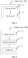
- FIG. 5 is a schematic structural diagram of a base station according to an embodiment of the present invention, and the base station may be applied to the system shown in FIG. 1 .
- the base station 1000 may include a processing unit 11 and a sending unit 12.
- the processing unit 11 is configured to: control an operation of the base station, for example, perform S101, and configure measurement parameters for a terminal device.
- the sending unit 12 is configured to communicate with the terminal device, for example, may perform S102, and is configured to send the measurement parameters to the terminal device.
- the base station may further include a receiving unit (not shown), configured to communicate with the terminal device.
- the receiving unit may perform S104, and is configured to receive a measurement result reported by the terminal device.
- the base station 1000 may include a processing unit 11 and a sending unit 12.
- the processing unit 11 is configured to: control an operation of the base station, for example, perform S101, and configure measurement parameters for a terminal device.
- the sending unit 12 is configured to communicate with the terminal device, for example, may perform S
- the base station 1000 may further include the following unit (not shown): an analysis unit, configured to obtain channel and interference measurement results under various interference hypotheses through analysis based on the measurement result.
- an analysis unit configured to obtain channel and interference measurement results under various interference hypotheses through analysis based on the measurement result.
- the base station receives and obtains a channel measurement result obtained by the terminal device through measurement on each group of antenna ports, and may obtain a measurement result of interference of another TP to a serving TP through estimation, the interference measurement result may be approximately equal to a channel measurement result of the another TP, and the interference measurement result may include interference outside a coordinating cluster.
- the base station may further accurately obtain, based on a measurement result that is of the interference outside the coordinating cluster and that is obtained by the terminal device through measurement, an interference measurement result when the interference outside the coordinating cluster is removed.
- the terminal device when the measurement parameters of channel state information are configured for the terminal device, the terminal device is instructed, by using a quasi-co-location indication, to measure the channel state information on each group of antenna ports, and it is unnecessary that each interference hypothesis corresponds to a channel state information process to perform separate resource and signaling configuration, reducing resource overheads and signaling overheads of the base station.
- FIG. 6 is a schematic structural diagram of a terminal device according to an embodiment of the present invention.
- the terminal device 2000 may include a receiving unit 21 and a measurement unit 22, and may further include a sending unit 23. Detailed descriptions of the units are as follows:
- the receiving unit 21 is configured to receive measurement parameters of channel state information from a base station.
- the base station needs to perform channel and interference measurement for coordinated multipoint transmission, and therefore sends the measurement parameters of the channel state information to the terminal device.
- the receiving unit 21 of the terminal device receives the measurement parameters of the channel state information from the base station.
- the measurement parameters include a channel state information-reference signal configuration and a quasi-co-location indication
- the channel state information-reference signal configuration includes configurations of at least two groups of antenna ports
- the quasi-co-location indication is used to indicate whether the at least two groups of antenna ports have a quasi-co-location relationship.
- there is one channel state information-reference signal configuration there is one channel state information-reference signal configuration. For details, refer to the related description in FIG. 3 in the method embodiment. Details are not described herein again.
- the measurement unit 22 is configured to measure the channel state information based on the measurement parameters.
- the terminal device After receiving the measurement parameters of the channel state information from the base station, the terminal device obtains the channel state information-reference signal configuration and the quasi-co-location indication that are included in the measurement parameters. Based on a value of the quasi-co-location indication, if the quasi-co-location indication is that the at least two groups of antenna ports included in the channel state information-reference signal configuration do not have the quasi-co-location relationship, the terminal device measures reference signals sent by each group of antenna ports, to obtain a channel measurement result of each group of antenna ports. For details, refer to the related description in S103 in the method embodiment. Details are not described herein again.
- the sending unit 23 is configured to report a channel and interference measurement result to the base station based on instruction information.
- the terminal device reports the channel and interference measurement result to the base station based on the instruction information in the measurement parameters.
- the terminal device measures the channel state information on each group of antenna ports based on the quasi-co-location indication in the measurement parameters of the channel state information, and it is unnecessary that each interference hypothesis corresponds to a channel state information process to perform separate resource and signaling configuration, reducing resource overheads and signaling overheads of the base station.
- FIG. 7 shows another base station 3000 according to an embodiment of the present invention.
- the base station 3000 may include a transmitter 31, a receiver 32, a processor 33, and a memory 34.
- the transmitter 31, the receiver 32, the processor 33, and the memory 34 are connected to each other by using a bus 35.
- a related function implemented by the processing unit 11 in FIG. 5 may be implemented by one or more processors 33.
- a related function implemented by the sending unit 12 in FIG. 5 may be implemented by the transmitter 31.
- the receiver 32 may also implement a function of the foregoing receiving unit.
- the memory 34 includes but is not limited to a random access memory (Random Access Memory, RAM), a read-only memory (Read-Only Memory, ROM), an erasable programmable read only memory (Erasable Programmable Read Only Memory, EPROM), or a compact disc read-only memory (Compact Disc Read-Only Memory, CD-ROM).
- the memory 34 is configured to store related instructions and data.
- the transmitter 31 is configured to send data and/or a signal
- the receiver 32 is configured to receive data and/or a signal.
- the processor 33 may include one or more processors, for example, includes one or more central processing units (Central Processing Unit, CPU).
- CPU Central Processing Unit
- the processor 33 may be a single-core CPU, or may be a multi-core CPU.
- the processor 33 in the base station 3000 is configured to read program code stored in the memory 34, to perform a base station-related operation in the method embodiment, for example, an operation in S101, to configure measurement parameters of channel state information for a terminal device.
- a base station-related operation in the method embodiment for example, an operation in S101
- measurement parameters of channel state information for a terminal device for example, an operation in S101
- the transmitter 31 and the receiver 32 are configured to communicate with the terminal device.
- the transmitter 31 sends the measurement parameters to the terminal device, for example, performs an operation in S102 in the method embodiment.
- the receiver 32 receives a measurement result sent by the terminal device, for example, performs a base station-related operation in S104 in the method embodiment.
- a measurement result sent by the terminal device for example, performs a base station-related operation in S104 in the method embodiment.
- the terminal device when the measurement parameters of the channel state information are configured for the terminal device, the terminal device is instructed, by using a quasi-co-location indication, to measure the channel state information on each group of antenna ports, and it is unnecessary that each interference hypothesis corresponds to a channel state information process to perform separate resource and signaling configuration, reducing resource overheads and signaling overheads of the base station.
- FIG. 8 shows another terminal device 4000 according to an embodiment of the present invention.
- the terminal device 4000 may include a transmitter 41, a receiver 42, a processor 43, and a memory 44.
- the transmitter 41, the receiver 42, the processor 43, and the memory 44 are connected to each other by using a bus 45.
- the memory 44 includes but is not limited to a random access memory, a read-only memory, an erasable programmable read-only memory, or a compact disc read-only memory.
- the memory 44 is configured to store related instructions and data.
- the transmitter 41 is configured to send data
- the receiver 42 is configured to receive data.
- the processor 43 may be one or more central processing units. When the processor 43 is one CPU, the CPU may be a single-core CPU, or may be a multi-core CPU.
- the processor 43 in the terminal device 4000 is configured to read program code stored in the memory 44, to perform the following operations: receiving measurement parameters of channel state information from a base station, and performing channel measurement based on the measurement parameters, where for the measurement parameters and a channel measurement manner, refer to the related descriptions in the method embodiment.
- the processor 43 controls the terminal device 4000 to measure, based on a non zero power channel state information-reference signal configuration, the channel state information at time-frequency locations corresponding to each group of antenna ports.
- configurations of the at least two groups of antenna ports are included in the non zero power channel state information-reference signal configuration.
- a channel state information-reference signal configuration further includes a zero power channel state information-reference signal configuration, the zero power channel state information-reference signal configuration is used to instruct the terminal device to measure interference outside a coordinating cluster at a time-frequency location corresponding to a corresponding antenna port, and the coordinating cluster includes a plurality of transmission points that perform coordinated transmission.
- the operation of measuring the channel state information based on the measurement parameters by the processor 43 further includes: measuring, based on the zero power channel state information-reference signal configuration, the interference outside the coordinating cluster at the time-frequency location corresponding to the corresponding antenna port.
- a quasi-co-location indication is used to indicate whether the at least two groups of antenna ports have a quasi-co-location relationship is that the quasi-co-location indication is used to indicate whether channel state information reference signals sent by the at least two groups of antenna ports are from a same transmission point.
- a quasi-co-location indication is used to indicate whether the at least two groups of antenna ports have a quasi-co-location relationship is that the quasi-co-location indication is used to indicate whether channel state information reference signals sent by the at least two groups of antenna ports are from a same beam group.
- the measurement parameters include instruction information, used to instruct the terminal device to report at least one of the following: a channel energy value of each group of antenna ports in the channel state information-reference signal configuration, an interference energy value outside the coordinating cluster, a signal to interference plus noise ratio of each group of antenna ports in the channel state information-reference signal configuration when the interference outside the coordinating cluster is removed, and a signal to interference plus noise ratio of each group of antenna ports in the channel state information-reference signal configuration when there is the interference outside the coordinating cluster.
- the processor 43 further performs the following operation: reporting a channel and interference measurement result to the base station based on the instruction information.
- a configuration of the antenna port includes a quantity of antenna ports, a resource configuration, and a time unit configuration.
- the terminal device measures the channel state information on each group of antenna ports based on the quasi-co-location indication in the measurement parameters of the channel state information, and it is unnecessary that each interference hypothesis corresponds to a channel state information process to perform separate resource and signaling configuration, reducing resource overheads and signaling overheads of the base station.
- the disclosed system, apparatus, and method may be implemented in other manners.
- the described apparatus embodiment is merely an example.
- the unit division is merely logical function division and may be other division in actual implementation.
- a plurality of units or components may be combined or integrated into another system, or some features may be ignored or not performed.
- the displayed or discussed mutual couplings or direct couplings or communication connections may be implemented by using some interfaces.
- the indirect couplings or communication connections between the apparatuses or units may be implemented in electrical, mechanical, or other forms.
- the units described as separate parts may or may not be physically separate, and parts displayed as units may or may not be physical units, may be located in one position, or may be distributed on a plurality of network units. Some or all of the units may be selected based on actual requirements to achieve the objectives of the solutions of the embodiments.
- All or some of the foregoing embodiments may be implemented by software, hardware, firmware, or any combination thereof.
- the embodiments may be implemented completely or partially in a form of a computer program product.
- the computer program product includes one or more computer instructions.
- the computer program instructions When the computer program instructions are loaded and executed on a computer, the procedure or functions according to the embodiments of the present invention are all or partially generated.
- the computer may be a general-purpose computer, a dedicated computer, a computer network, or other programmable apparatuses.
- the computer instructions may be stored in a computer-readable storage medium, or may be transmitted by using the computer-readable storage medium.
- the computer instructions may be transmitted from a website, computer, server, or data center to another website, computer, server, or data center in a wired (for example, a coaxial cable, an optical fiber, or a digital subscriber line (DSL)) or wireless (for example, infrared, radio, or microwave) manner.
- the computer-readable storage medium may be any usable medium accessible by a computer, or a data storage device, such as a server or a data center, integrating one or more usable media.
- the usable medium may be a magnetic medium (for example, a floppy disk, a hard disk, or a magnetic tape), an optical medium (for example, a DVD), a semiconductor medium (for example, a solid state disk Solid State Disk (SSD)), or the like.
- a person of ordinary skill in the art may understand that all or some of the processes of the methods in the embodiments may be implemented by a computer program instructing related hardware.
- the program may be stored in a computer-readable storage medium. When the program runs, the processes of the methods in the embodiments are performed.
- the foregoing storage medium includes: any medium that can store program code, such as a ROM or a random access memory RAM, a magnetic disk or an optical disc, or the like.
Landscapes
- Engineering & Computer Science (AREA)
- Signal Processing (AREA)
- Computer Networks & Wireless Communication (AREA)
- Quality & Reliability (AREA)
- Physics & Mathematics (AREA)
- Electromagnetism (AREA)
- Mobile Radio Communication Systems (AREA)
Applications Claiming Priority (2)
| Application Number | Priority Date | Filing Date | Title |
|---|---|---|---|
| CN201710057695.0A CN108365931B (zh) | 2017-01-26 | 2017-01-26 | 用于无线通信的方法及装置 |
| PCT/CN2017/118125 WO2018137450A1 (zh) | 2017-01-26 | 2017-12-22 | 用于无线通信的方法及装置 |
Publications (3)
| Publication Number | Publication Date |
|---|---|
| EP3573273A1 true EP3573273A1 (de) | 2019-11-27 |
| EP3573273A4 EP3573273A4 (de) | 2020-01-01 |
| EP3573273B1 EP3573273B1 (de) | 2024-09-18 |
Family
ID=62979134
Family Applications (1)
| Application Number | Title | Priority Date | Filing Date |
|---|---|---|---|
| EP17893627.4A Active EP3573273B1 (de) | 2017-01-26 | 2017-12-22 | Verfahren und vorrichtung zur drahtloskommunikation |
Country Status (4)
| Country | Link |
|---|---|
| US (1) | US10951332B2 (de) |
| EP (1) | EP3573273B1 (de) |
| CN (1) | CN108365931B (de) |
| WO (1) | WO2018137450A1 (de) |
Cited By (2)
| Publication number | Priority date | Publication date | Assignee | Title |
|---|---|---|---|---|
| WO2021214713A1 (en) * | 2020-04-24 | 2021-10-28 | Lenovo (Singapore) Pte. Ltd. | Channel state information reporting |
| EP3834331A4 (de) * | 2018-08-10 | 2022-03-23 | Qualcomm Incorporated | Quasi-kollokationsanzeige für kanalgruppen von nicht-null-leistungskanalzustandsinformations-referenzsignalen |
Families Citing this family (18)
| Publication number | Priority date | Publication date | Assignee | Title |
|---|---|---|---|---|
| CN108668363A (zh) * | 2017-03-28 | 2018-10-16 | 索尼公司 | 无线通信系统中的电子设备和方法 |
| US11218210B2 (en) * | 2017-05-30 | 2022-01-04 | Telefonaktiebolaget Lm Ericsson (Publ) | Technique for channel state acquisition |
| CN109586819A (zh) * | 2017-09-29 | 2019-04-05 | 电信科学技术研究院 | 一种干扰测量方法、用户终端和网络侧设备 |
| WO2020050683A1 (ko) * | 2018-09-06 | 2020-03-12 | 엘지전자 주식회사 | 무선 통신 시스템에서 단말 및 기지국의 동작 방법 및 이를 지원하는 장치 |
| US11316732B2 (en) * | 2018-10-05 | 2022-04-26 | Qualcomm Incorporated | User equipment processing for multi-TRP and MU-MIMO communications |
| CN109635481B (zh) * | 2018-12-22 | 2023-05-12 | 成都毅创空间科技有限公司 | 一种用于穿戴设备的数据分析系统 |
| US11881905B2 (en) * | 2019-01-03 | 2024-01-23 | Samsung Electronics Co., Ltd. | Method and apparatus for interference measurement |
| CN111510268B (zh) * | 2019-01-31 | 2023-05-09 | 中国移动通信有限公司研究院 | 一种测量配置方法、测量方法、终端及网络侧设备 |
| CN113079540B (zh) * | 2020-01-06 | 2022-06-24 | 大唐移动通信设备有限公司 | 一种下行数据的处理方法和装置 |
| CN115399019B (zh) * | 2020-04-08 | 2025-04-18 | 苹果公司 | 用于无线通信中的信道状态信息反馈的介质和用户装备 |
| US11394475B1 (en) * | 2020-11-04 | 2022-07-19 | Spectrum Effect Inc. | Method and system for interference detection and classification |
| US12574077B2 (en) * | 2021-05-11 | 2026-03-10 | Telefonaktiebolaget Lm Ericsson (Publ) | Configuring channel state information (CSI) feedback |
| US11924124B2 (en) * | 2021-05-24 | 2024-03-05 | Samsung Electronics Co., Ltd. | Set of rules for triggering coordinated beamforming |
| CN115483952B (zh) * | 2021-05-31 | 2025-09-05 | 华为技术有限公司 | 一种确定天线的信道状态的方法及装置 |
| CN115551101A (zh) * | 2021-06-30 | 2022-12-30 | 中国移动通信集团广东有限公司 | 一种天线混配下的超级小区调度方法及装置 |
| CN118355686A (zh) * | 2021-12-15 | 2024-07-16 | 索尼集团公司 | 终端设备、通信设备和通信方法 |
| US12513732B2 (en) * | 2022-04-12 | 2025-12-30 | Samsung Electronics Co., Ltd. | TRP subset selection and reporting |
| CN119301894A (zh) * | 2023-04-25 | 2025-01-10 | 上海传英信息技术有限公司 | 处理方法、通信设备及存储介质 |
Family Cites Families (15)
| Publication number | Priority date | Publication date | Assignee | Title |
|---|---|---|---|---|
| US9008585B2 (en) * | 2012-01-30 | 2015-04-14 | Futurewei Technologies, Inc. | System and method for wireless communications measurements and CSI feedback |
| JP6242857B2 (ja) * | 2012-04-19 | 2017-12-06 | サムスン エレクトロニクス カンパニー リミテッド | 協力マルチーポイント通信システムに対する基準シンボルポートの準共存識別のための方法及び装置 |
| CN103427967B (zh) * | 2012-05-18 | 2018-05-01 | 中兴通讯股份有限公司 | 一种干扰测量资源的管理方法和系统 |
| KR20130130593A (ko) * | 2012-05-22 | 2013-12-02 | 삼성전자주식회사 | 분산 안테나를 사용하는 복수 개의 기지국을 포함하는 무선통신 시스템에서 기준 신호 측정 방법 및 장치 |
| US20140022988A1 (en) * | 2012-07-20 | 2014-01-23 | Alexei Davydov | User equipment and method for antenna port quasi co-location signaling in coordinated multi-point operations |
| US9106386B2 (en) * | 2012-08-03 | 2015-08-11 | Intel Corporation | Reference signal configuration for coordinated multipoint |
| CN103684676B (zh) * | 2012-09-26 | 2018-05-15 | 中兴通讯股份有限公司 | 天线端口位置关系的通知和确定方法、系统及装置 |
| US9307521B2 (en) * | 2012-11-01 | 2016-04-05 | Samsung Electronics Co., Ltd. | Transmission scheme and quasi co-location assumption of antenna ports for PDSCH of transmission mode 10 for LTE advanced |
| CN103812624A (zh) * | 2012-11-07 | 2014-05-21 | 上海贝尔股份有限公司 | 协同多点传输的方法 |
| CN110602743B (zh) * | 2013-01-18 | 2022-09-09 | 北京三星通信技术研究有限公司 | 一种进行下行信道特性参数测量的方法及用户设备 |
| US10103797B2 (en) * | 2013-03-01 | 2018-10-16 | Intel IP Corporation | Quasi co-location and PDSCH resource element mapping signaling for network assisted interference mitigation |
| CN104811288B (zh) * | 2014-01-29 | 2019-11-29 | 上海诺基亚贝尔股份有限公司 | 协同多点传输的方法 |
| US10084577B2 (en) * | 2015-01-30 | 2018-09-25 | Motorola Mobility Llc | Method and apparatus for signaling aperiodic channel state indication reference signals for LTE operation |
| US10057027B2 (en) * | 2015-05-07 | 2018-08-21 | Electronics And Telecommunications Research Institute | Method and apparatus for receiving reference signal |
| WO2017165447A1 (en) * | 2016-03-24 | 2017-09-28 | Intel Corporation | Measurement restrictions for comp |
-
2017
- 2017-01-26 CN CN201710057695.0A patent/CN108365931B/zh active Active
- 2017-12-22 WO PCT/CN2017/118125 patent/WO2018137450A1/zh not_active Ceased
- 2017-12-22 EP EP17893627.4A patent/EP3573273B1/de active Active
-
2019
- 2019-07-24 US US16/521,376 patent/US10951332B2/en active Active
Cited By (7)
| Publication number | Priority date | Publication date | Assignee | Title |
|---|---|---|---|---|
| EP3834331A4 (de) * | 2018-08-10 | 2022-03-23 | Qualcomm Incorporated | Quasi-kollokationsanzeige für kanalgruppen von nicht-null-leistungskanalzustandsinformations-referenzsignalen |
| US11863268B2 (en) | 2018-08-10 | 2024-01-02 | Qualcomm Incorporated | Quasi-colocation indication for non-zero power channel state information reference signal port groups |
| WO2021214713A1 (en) * | 2020-04-24 | 2021-10-28 | Lenovo (Singapore) Pte. Ltd. | Channel state information reporting |
| WO2021214710A1 (en) * | 2020-04-24 | 2021-10-28 | Lenovo (Singapore) Pte. Ltd. | Channel state information reporting |
| CN115428507A (zh) * | 2020-04-24 | 2022-12-02 | 联想(新加坡)私人有限公司 | 信道状态信息报告 |
| US20230171623A1 (en) * | 2020-04-24 | 2023-06-01 | Lenovo (Singapore) Pte. Ltd. | Channel state information reporting |
| US12432588B2 (en) * | 2020-04-24 | 2025-09-30 | Lenovo (Singapore) Pte. Ltd. | Channel state information reporting |
Also Published As
| Publication number | Publication date |
|---|---|
| US10951332B2 (en) | 2021-03-16 |
| CN108365931B (zh) | 2024-09-24 |
| EP3573273A4 (de) | 2020-01-01 |
| US20190349103A1 (en) | 2019-11-14 |
| CN108365931A (zh) | 2018-08-03 |
| EP3573273B1 (de) | 2024-09-18 |
| WO2018137450A1 (zh) | 2018-08-02 |
Similar Documents
| Publication | Publication Date | Title |
|---|---|---|
| US10951332B2 (en) | Method and apparatus for coordinated multipoint (CoMP) communication using quasi-co-location | |
| US11936584B2 (en) | System and method for control signaling | |
| US11283503B2 (en) | Communication method and communications apparatus | |
| US10498416B2 (en) | System and method for downlink channel sounding in wireless communications systems | |
| CN108282297B (zh) | 一种资源指示方法、装置及系统 | |
| EP4087345B1 (de) | Strahlenpaartrainingsverfahren und kommunikationsgerät | |
| US20200028547A1 (en) | Method and device for acquiring and feeding back transmission beam information | |
| CN117998381A (zh) | 用于通信波束恢复的系统和方法 | |
| WO2019140389A1 (en) | User equipment and wireless communication method | |
| WO2021052473A1 (zh) | 通信方法和通信装置 | |
| JP2017536053A (ja) | リソース設定方法、ユーザ機器、及び基地局 | |
| US20190229783A1 (en) | Communication method and network device | |
| CN107395332B (zh) | 一种cqi确定方法、用户设备和基站 | |
| EP3496508B1 (de) | Benutzerendgerät und drahtloskommunikationsverfahren | |
| EP3613248B1 (de) | System und verfahren zur anzeige von planungsgenehmigungen | |
| US20180309491A1 (en) | Csi receiving method and access network device | |
| JP7216813B2 (ja) | チャネル状態情報を決定するための方法および装置 | |
| CN116094670B (zh) | 信号处理方法及装置 | |
| JP7197488B2 (ja) | ユーザ端末、無線通信方法、基地局及び通信システム |
Legal Events
| Date | Code | Title | Description |
|---|---|---|---|
| STAA | Information on the status of an ep patent application or granted ep patent |
Free format text: STATUS: THE INTERNATIONAL PUBLICATION HAS BEEN MADE |
|
| PUAI | Public reference made under article 153(3) epc to a published international application that has entered the european phase |
Free format text: ORIGINAL CODE: 0009012 |
|
| STAA | Information on the status of an ep patent application or granted ep patent |
Free format text: STATUS: REQUEST FOR EXAMINATION WAS MADE |
|
| 17P | Request for examination filed |
Effective date: 20190819 |
|
| AK | Designated contracting states |
Kind code of ref document: A1 Designated state(s): AL AT BE BG CH CY CZ DE DK EE ES FI FR GB GR HR HU IE IS IT LI LT LU LV MC MK MT NL NO PL PT RO RS SE SI SK SM TR |
|
| AX | Request for extension of the european patent |
Extension state: BA ME |
|
| A4 | Supplementary search report drawn up and despatched |
Effective date: 20191203 |
|
| RIC1 | Information provided on ipc code assigned before grant |
Ipc: H04L 5/00 20060101AFI20191127BHEP |
|
| DAV | Request for validation of the european patent (deleted) | ||
| DAX | Request for extension of the european patent (deleted) | ||
| STAA | Information on the status of an ep patent application or granted ep patent |
Free format text: STATUS: EXAMINATION IS IN PROGRESS |
|
| 17Q | First examination report despatched |
Effective date: 20201023 |
|
| GRAP | Despatch of communication of intention to grant a patent |
Free format text: ORIGINAL CODE: EPIDOSNIGR1 |
|
| STAA | Information on the status of an ep patent application or granted ep patent |
Free format text: STATUS: GRANT OF PATENT IS INTENDED |
|
| INTG | Intention to grant announced |
Effective date: 20240416 |
|
| GRAS | Grant fee paid |
Free format text: ORIGINAL CODE: EPIDOSNIGR3 |
|
| GRAA | (expected) grant |
Free format text: ORIGINAL CODE: 0009210 |
|
| STAA | Information on the status of an ep patent application or granted ep patent |
Free format text: STATUS: THE PATENT HAS BEEN GRANTED |
|
| AK | Designated contracting states |
Kind code of ref document: B1 Designated state(s): AL AT BE BG CH CY CZ DE DK EE ES FI FR GB GR HR HU IE IS IT LI LT LU LV MC MK MT NL NO PL PT RO RS SE SI SK SM TR |
|
| REG | Reference to a national code |
Ref country code: GB Ref legal event code: FG4D |
|
| REG | Reference to a national code |
Ref country code: CH Ref legal event code: EP |
|
| REG | Reference to a national code |
Ref country code: DE Ref legal event code: R096 Ref document number: 602017084983 Country of ref document: DE |
|
| REG | Reference to a national code |
Ref country code: IE Ref legal event code: FG4D |
|
| REG | Reference to a national code |
Ref country code: LT Ref legal event code: MG9D |
|
| PG25 | Lapsed in a contracting state [announced via postgrant information from national office to epo] |
Ref country code: NO Free format text: LAPSE BECAUSE OF FAILURE TO SUBMIT A TRANSLATION OF THE DESCRIPTION OR TO PAY THE FEE WITHIN THE PRESCRIBED TIME-LIMIT Effective date: 20241218 |
|
| PG25 | Lapsed in a contracting state [announced via postgrant information from national office to epo] |
Ref country code: GR Free format text: LAPSE BECAUSE OF FAILURE TO SUBMIT A TRANSLATION OF THE DESCRIPTION OR TO PAY THE FEE WITHIN THE PRESCRIBED TIME-LIMIT Effective date: 20241219 Ref country code: FI Free format text: LAPSE BECAUSE OF FAILURE TO SUBMIT A TRANSLATION OF THE DESCRIPTION OR TO PAY THE FEE WITHIN THE PRESCRIBED TIME-LIMIT Effective date: 20240918 |
|
| PG25 | Lapsed in a contracting state [announced via postgrant information from national office to epo] |
Ref country code: BG Free format text: LAPSE BECAUSE OF FAILURE TO SUBMIT A TRANSLATION OF THE DESCRIPTION OR TO PAY THE FEE WITHIN THE PRESCRIBED TIME-LIMIT Effective date: 20240918 |
|
| PG25 | Lapsed in a contracting state [announced via postgrant information from national office to epo] |
Ref country code: LV Free format text: LAPSE BECAUSE OF FAILURE TO SUBMIT A TRANSLATION OF THE DESCRIPTION OR TO PAY THE FEE WITHIN THE PRESCRIBED TIME-LIMIT Effective date: 20240918 |
|
| PG25 | Lapsed in a contracting state [announced via postgrant information from national office to epo] |
Ref country code: HR Free format text: LAPSE BECAUSE OF FAILURE TO SUBMIT A TRANSLATION OF THE DESCRIPTION OR TO PAY THE FEE WITHIN THE PRESCRIBED TIME-LIMIT Effective date: 20240918 |
|
| REG | Reference to a national code |
Ref country code: NL Ref legal event code: MP Effective date: 20240918 |
|
| PG25 | Lapsed in a contracting state [announced via postgrant information from national office to epo] |
Ref country code: RS Free format text: LAPSE BECAUSE OF FAILURE TO SUBMIT A TRANSLATION OF THE DESCRIPTION OR TO PAY THE FEE WITHIN THE PRESCRIBED TIME-LIMIT Effective date: 20241218 |
|
| PG25 | Lapsed in a contracting state [announced via postgrant information from national office to epo] |
Ref country code: RS Free format text: LAPSE BECAUSE OF FAILURE TO SUBMIT A TRANSLATION OF THE DESCRIPTION OR TO PAY THE FEE WITHIN THE PRESCRIBED TIME-LIMIT Effective date: 20241218 Ref country code: NO Free format text: LAPSE BECAUSE OF FAILURE TO SUBMIT A TRANSLATION OF THE DESCRIPTION OR TO PAY THE FEE WITHIN THE PRESCRIBED TIME-LIMIT Effective date: 20241218 Ref country code: LV Free format text: LAPSE BECAUSE OF FAILURE TO SUBMIT A TRANSLATION OF THE DESCRIPTION OR TO PAY THE FEE WITHIN THE PRESCRIBED TIME-LIMIT Effective date: 20240918 Ref country code: HR Free format text: LAPSE BECAUSE OF FAILURE TO SUBMIT A TRANSLATION OF THE DESCRIPTION OR TO PAY THE FEE WITHIN THE PRESCRIBED TIME-LIMIT Effective date: 20240918 Ref country code: GR Free format text: LAPSE BECAUSE OF FAILURE TO SUBMIT A TRANSLATION OF THE DESCRIPTION OR TO PAY THE FEE WITHIN THE PRESCRIBED TIME-LIMIT Effective date: 20241219 Ref country code: FI Free format text: LAPSE BECAUSE OF FAILURE TO SUBMIT A TRANSLATION OF THE DESCRIPTION OR TO PAY THE FEE WITHIN THE PRESCRIBED TIME-LIMIT Effective date: 20240918 Ref country code: BG Free format text: LAPSE BECAUSE OF FAILURE TO SUBMIT A TRANSLATION OF THE DESCRIPTION OR TO PAY THE FEE WITHIN THE PRESCRIBED TIME-LIMIT Effective date: 20240918 |
|
| REG | Reference to a national code |
Ref country code: AT Ref legal event code: MK05 Ref document number: 1725581 Country of ref document: AT Kind code of ref document: T Effective date: 20240918 |
|
| PG25 | Lapsed in a contracting state [announced via postgrant information from national office to epo] |
Ref country code: NL Free format text: LAPSE BECAUSE OF FAILURE TO SUBMIT A TRANSLATION OF THE DESCRIPTION OR TO PAY THE FEE WITHIN THE PRESCRIBED TIME-LIMIT Effective date: 20240918 |
|
| PG25 | Lapsed in a contracting state [announced via postgrant information from national office to epo] |
Ref country code: PT Free format text: LAPSE BECAUSE OF FAILURE TO SUBMIT A TRANSLATION OF THE DESCRIPTION OR TO PAY THE FEE WITHIN THE PRESCRIBED TIME-LIMIT Effective date: 20250120 Ref country code: IS Free format text: LAPSE BECAUSE OF FAILURE TO SUBMIT A TRANSLATION OF THE DESCRIPTION OR TO PAY THE FEE WITHIN THE PRESCRIBED TIME-LIMIT Effective date: 20250118 |
|
| PG25 | Lapsed in a contracting state [announced via postgrant information from national office to epo] |
Ref country code: RO Free format text: LAPSE BECAUSE OF FAILURE TO SUBMIT A TRANSLATION OF THE DESCRIPTION OR TO PAY THE FEE WITHIN THE PRESCRIBED TIME-LIMIT Effective date: 20240918 Ref country code: SM Free format text: LAPSE BECAUSE OF FAILURE TO SUBMIT A TRANSLATION OF THE DESCRIPTION OR TO PAY THE FEE WITHIN THE PRESCRIBED TIME-LIMIT Effective date: 20240918 |
|
| PG25 | Lapsed in a contracting state [announced via postgrant information from national office to epo] |
Ref country code: ES Free format text: LAPSE BECAUSE OF FAILURE TO SUBMIT A TRANSLATION OF THE DESCRIPTION OR TO PAY THE FEE WITHIN THE PRESCRIBED TIME-LIMIT Effective date: 20240918 |
|
| PG25 | Lapsed in a contracting state [announced via postgrant information from national office to epo] |
Ref country code: AT Free format text: LAPSE BECAUSE OF FAILURE TO SUBMIT A TRANSLATION OF THE DESCRIPTION OR TO PAY THE FEE WITHIN THE PRESCRIBED TIME-LIMIT Effective date: 20240918 Ref country code: EE Free format text: LAPSE BECAUSE OF FAILURE TO SUBMIT A TRANSLATION OF THE DESCRIPTION OR TO PAY THE FEE WITHIN THE PRESCRIBED TIME-LIMIT Effective date: 20240918 |
|
| PG25 | Lapsed in a contracting state [announced via postgrant information from national office to epo] |
Ref country code: CZ Free format text: LAPSE BECAUSE OF FAILURE TO SUBMIT A TRANSLATION OF THE DESCRIPTION OR TO PAY THE FEE WITHIN THE PRESCRIBED TIME-LIMIT Effective date: 20240918 Ref country code: PL Free format text: LAPSE BECAUSE OF FAILURE TO SUBMIT A TRANSLATION OF THE DESCRIPTION OR TO PAY THE FEE WITHIN THE PRESCRIBED TIME-LIMIT Effective date: 20240918 |
|
| PG25 | Lapsed in a contracting state [announced via postgrant information from national office to epo] |
Ref country code: IT Free format text: LAPSE BECAUSE OF FAILURE TO SUBMIT A TRANSLATION OF THE DESCRIPTION OR TO PAY THE FEE WITHIN THE PRESCRIBED TIME-LIMIT Effective date: 20240918 Ref country code: SK Free format text: LAPSE BECAUSE OF FAILURE TO SUBMIT A TRANSLATION OF THE DESCRIPTION OR TO PAY THE FEE WITHIN THE PRESCRIBED TIME-LIMIT Effective date: 20240918 |
|
| REG | Reference to a national code |
Ref country code: DE Ref legal event code: R097 Ref document number: 602017084983 Country of ref document: DE |
|
| PG25 | Lapsed in a contracting state [announced via postgrant information from national office to epo] |
Ref country code: MC Free format text: LAPSE BECAUSE OF FAILURE TO SUBMIT A TRANSLATION OF THE DESCRIPTION OR TO PAY THE FEE WITHIN THE PRESCRIBED TIME-LIMIT Effective date: 20240918 |
|
| PG25 | Lapsed in a contracting state [announced via postgrant information from national office to epo] |
Ref country code: DK Free format text: LAPSE BECAUSE OF FAILURE TO SUBMIT A TRANSLATION OF THE DESCRIPTION OR TO PAY THE FEE WITHIN THE PRESCRIBED TIME-LIMIT Effective date: 20240918 |
|
| PLBE | No opposition filed within time limit |
Free format text: ORIGINAL CODE: 0009261 |
|
| STAA | Information on the status of an ep patent application or granted ep patent |
Free format text: STATUS: NO OPPOSITION FILED WITHIN TIME LIMIT |
|
| REG | Reference to a national code |
Ref country code: CH Ref legal event code: PL |
|
| PG25 | Lapsed in a contracting state [announced via postgrant information from national office to epo] |
Ref country code: LU Free format text: LAPSE BECAUSE OF NON-PAYMENT OF DUE FEES Effective date: 20241222 |
|
| 26N | No opposition filed |
Effective date: 20250619 |
|
| PG25 | Lapsed in a contracting state [announced via postgrant information from national office to epo] |
Ref country code: SE Free format text: LAPSE BECAUSE OF FAILURE TO SUBMIT A TRANSLATION OF THE DESCRIPTION OR TO PAY THE FEE WITHIN THE PRESCRIBED TIME-LIMIT Effective date: 20240918 |
|
| REG | Reference to a national code |
Ref country code: BE Ref legal event code: MM Effective date: 20241231 |
|
| PG25 | Lapsed in a contracting state [announced via postgrant information from national office to epo] |
Ref country code: BE Free format text: LAPSE BECAUSE OF NON-PAYMENT OF DUE FEES Effective date: 20241231 |
|
| PG25 | Lapsed in a contracting state [announced via postgrant information from national office to epo] |
Ref country code: FR Free format text: LAPSE BECAUSE OF NON-PAYMENT OF DUE FEES Effective date: 20241231 |
|
| PG25 | Lapsed in a contracting state [announced via postgrant information from national office to epo] |
Ref country code: CH Free format text: LAPSE BECAUSE OF NON-PAYMENT OF DUE FEES Effective date: 20241231 |
|
| PG25 | Lapsed in a contracting state [announced via postgrant information from national office to epo] |
Ref country code: IE Free format text: LAPSE BECAUSE OF NON-PAYMENT OF DUE FEES Effective date: 20241222 |
|
| PGFP | Annual fee paid to national office [announced via postgrant information from national office to epo] |
Ref country code: DE Payment date: 20251104 Year of fee payment: 9 |
|
| PGFP | Annual fee paid to national office [announced via postgrant information from national office to epo] |
Ref country code: GB Payment date: 20251030 Year of fee payment: 9 |