EP3573356A1 - Procédé de contrôle d'états de dispositif terminal, dispositif terminal, et dispositif de réseau - Google Patents
Procédé de contrôle d'états de dispositif terminal, dispositif terminal, et dispositif de réseau Download PDFInfo
- Publication number
- EP3573356A1 EP3573356A1 EP18770505.8A EP18770505A EP3573356A1 EP 3573356 A1 EP3573356 A1 EP 3573356A1 EP 18770505 A EP18770505 A EP 18770505A EP 3573356 A1 EP3573356 A1 EP 3573356A1
- Authority
- EP
- European Patent Office
- Prior art keywords
- terminal device
- network device
- information
- response message
- inactive state
- Prior art date
- Legal status (The legal status is an assumption and is not a legal conclusion. Google has not performed a legal analysis and makes no representation as to the accuracy of the status listed.)
- Granted
Links
Images





Classifications
-
- H—ELECTRICITY
- H04—ELECTRIC COMMUNICATION TECHNIQUE
- H04W—WIRELESS COMMUNICATION NETWORKS
- H04W76/00—Connection management
- H04W76/20—Manipulation of established connections
- H04W76/25—Maintenance of established connections
-
- H—ELECTRICITY
- H04—ELECTRIC COMMUNICATION TECHNIQUE
- H04W—WIRELESS COMMUNICATION NETWORKS
- H04W8/00—Network data management
- H04W8/22—Processing or transfer of terminal data, e.g. status or physical capabilities
- H04W8/24—Transfer of terminal data
- H04W8/245—Transfer of terminal data from a network towards a terminal
-
- H—ELECTRICITY
- H04—ELECTRIC COMMUNICATION TECHNIQUE
- H04W—WIRELESS COMMUNICATION NETWORKS
- H04W52/00—Power management, e.g. Transmission Power Control [TPC] or power classes
- H04W52/02—Power saving arrangements
- H04W52/0209—Power saving arrangements in terminal devices
- H04W52/0225—Power saving arrangements in terminal devices using monitoring of external events, e.g. the presence of a signal
- H04W52/0229—Power saving arrangements in terminal devices using monitoring of external events, e.g. the presence of a signal where the received signal is a wanted signal
- H04W52/0235—Power saving arrangements in terminal devices using monitoring of external events, e.g. the presence of a signal where the received signal is a wanted signal where the received signal is a power saving command
-
- H—ELECTRICITY
- H04—ELECTRIC COMMUNICATION TECHNIQUE
- H04W—WIRELESS COMMUNICATION NETWORKS
- H04W52/00—Power management, e.g. Transmission Power Control [TPC] or power classes
- H04W52/02—Power saving arrangements
- H04W52/0209—Power saving arrangements in terminal devices
- H04W52/0225—Power saving arrangements in terminal devices using monitoring of external events, e.g. the presence of a signal
-
- H—ELECTRICITY
- H04—ELECTRIC COMMUNICATION TECHNIQUE
- H04W—WIRELESS COMMUNICATION NETWORKS
- H04W76/00—Connection management
- H04W76/10—Connection setup
- H04W76/11—Allocation or use of connection identifiers
-
- H—ELECTRICITY
- H04—ELECTRIC COMMUNICATION TECHNIQUE
- H04W—WIRELESS COMMUNICATION NETWORKS
- H04W76/00—Connection management
- H04W76/20—Manipulation of established connections
- H04W76/27—Transitions between radio resource control [RRC] states
-
- Y—GENERAL TAGGING OF NEW TECHNOLOGICAL DEVELOPMENTS; GENERAL TAGGING OF CROSS-SECTIONAL TECHNOLOGIES SPANNING OVER SEVERAL SECTIONS OF THE IPC; TECHNICAL SUBJECTS COVERED BY FORMER USPC CROSS-REFERENCE ART COLLECTIONS [XRACs] AND DIGESTS
- Y02—TECHNOLOGIES OR APPLICATIONS FOR MITIGATION OR ADAPTATION AGAINST CLIMATE CHANGE
- Y02D—CLIMATE CHANGE MITIGATION TECHNOLOGIES IN INFORMATION AND COMMUNICATION TECHNOLOGIES [ICT], I.E. INFORMATION AND COMMUNICATION TECHNOLOGIES AIMING AT THE REDUCTION OF THEIR OWN ENERGY USE
- Y02D30/00—Reducing energy consumption in communication networks
- Y02D30/70—Reducing energy consumption in communication networks in wireless communication networks
Definitions
- This application relates to the communications field, and more specifically, to a method for controlling a status of a terminal device, a terminal device, and a network device.
- a fifth-generation (5th-Generation, 5G) mobile communications technology newly defines a radio resource control (Radio Resource Control, RRC) inactive state (inactive state), short as an inactive state.
- the inactive state may be considered as a state independent of an RRC connected (connected) state (connected state for short) and an RRC idle (idle) state (idle state for short); or may be considered as a substate of the connected state or the idle state.
- the inactive state has the following features: 1. When a terminal device is transferred from the inactive state to the connected state in an anchor base station or an anchor cell, the terminal device does not need to reactivate a link between the anchor base station or the anchor cell and a core network control plane network element. 2. Mobility of the terminal device is implemented through cell reselection rather than cell handover.
- the 5G mobile communications technology further defines a radio access network (Radio Access Network, RAN)-based notification area (RAN based Notification Area, RNA).
- the RNA may include one or more cells. If the RNA includes a plurality of cells, the plurality of cells may be served by one base station (which may be, for example, an eNB or a gNB), or may be served by a plurality of base stations (which may include, for example, an eNB and/or a gNB).
- the eNB may be an evolved NodeB (evolved Node B) in a 4.5G mobile communications technology.
- the terminal device may not notify a network device, but only performs cell reselection. However, when the terminal device moves to a cell outside the RNA, the terminal device needs to notify the network device, and then updates the RNA.
- This application provides a method for controlling a status of a terminal device, a terminal device, and a network device, to reduce signaling overheads and reduce power consumption of the terminal device.
- a method for controlling a status of a terminal device includes: sending, by a terminal device in an inactive state, a first request message to a first network device, where the first request message includes first identifier information of the terminal device; and receiving, by the terminal device, a first response message sent by the first network device, where the first response message is used to instruct the terminal device to enter an idle state or enter the inactive state.
- a method for controlling a status of a terminal device includes: receiving, by a first network device, a first request message sent by a terminal device in an inactive state, where the first request message includes first identifier information of the terminal device; and sending, by the first network device, a first response message to the terminal device, where the first response message is used to instruct the terminal device to enter an idle state or enter the inactive state.
- the terminal device in the inactive state sends a request message to the first network device, the first network device instructs the terminal device to directly enter the idle state or the inactive state, and the terminal device does not need to switch to a connected state in advance, so that signaling overheads can be reduced, and power consumption of the terminal device can be reduced.
- the method before the sending, by the first network device, a first response message to the terminal device, the method further includes: determining, by the first network device based on the first request message, to set the terminal device to the idle state or set the terminal device to the inactive state.
- the first network device determines, based on request information, a state to which the terminal device should be set, thereby more flexibly and efficiently controlling the status of the terminal device.
- the method further includes: when determining to set the terminal device to the idle state, sending, by the first network device, a second request message to a second network device, where the second request message is used to instruct to delete a terminal device context; and receiving, by the first network device, a second response message sent by the second network device, where the second response message is used to feed back a result of deleting the terminal device context.
- This possible implementation is applicable to a case of determining to set the terminal device to the idle state.
- the method further includes: when determining to set the terminal device to the inactive state, sending, by the first network device, a third request message to the second network device, where the third request message is used to instruct to request the terminal device context; and receiving, by the first network device, a third response message sent by the second network device, where the third response message is used to feed back the terminal device context.
- This possible implementation is applicable to a case of determining to set the terminal device to the inactive state.
- the first identifier information is inactive state identifier information allocated by the second network device for the terminal device in the inactive state.
- ID information of the terminal device uniquely corresponds to a context of the terminal device, and for the convenience of implementing a subsequent procedure, the first request message may carry the inactive state identifier information allocated by the second network device for the terminal device in the inactive state.
- the inactive state ID information of the terminal device may be access stratum (Access Stratum, AS) ID information.
- the first response message when the first response message is used to instruct the terminal device to enter the inactive state, the first response message includes second identifier information allocated by the first network device to the terminal device. In this possible implementation, the first response message includes the second identifier information allocated by the first network device to the terminal device, to facilitate update of the terminal device.
- the first response message when the first response message is used to instruct the terminal device to enter the inactive state, the first response message includes state indicator information, and the state indicator information is used to instruct the terminal device to enter the inactive state rather than a connected state.
- the terminal device is instructed to enter the inactive state in an explicit manner.
- the first request message further includes at least one of second network device identifier information, anchor cell identifier information, service type information, slice indicator information, expected state information, and first cause information.
- the second network device identifier information and the anchor cell identifier information may assist the first network device in determining the second network device of the terminal device in the inactive state;
- the service type information and the slice indicator information may be used by the first network device to perform RRC layer access control;
- the expected state information may indicate a state that the terminal device expects to enter after sending the first request message, to help the first network device make determining;
- the first cause information may indicate a cause for sending the first request message, to help the first network device make determining.
- the first cause information is used to indicate that the cause is update of a radio access network RAN-based notification area RNA.
- the first cause information is used to indicate that the cause is periodic update of the RNA.
- the first request message may be a radio resource control RRC connection resume request message.
- the first response message When the first response message is used to instruct the terminal device to enter the inactive state, the first response message may be an RRC connection resume message or an RRC connection reconfiguration message.
- the first response message When the first response message is used to instruct the terminal device to enter the idle state, the first response message may be an RRC connection reject message.
- a third aspect provides a terminal device, and the terminal device is in an inactive state and includes: a sending module, configured to send a first request message to a first network device, where the first request message includes first identifier information of the terminal device; and a receiving module, configured to receive a first response message sent by the first network device, where the first response message is used to instruct the terminal device to enter an idle state or enter the inactive state.
- the first identifier information is inactive state identifier information allocated by a second network device for the terminal device in the inactive state.
- the first response message when the first response message is used to instruct the terminal device to enter the inactive state, the first response message includes second identifier information allocated by the first network device to the terminal device.
- the first response message when used to instruct the terminal device to enter the inactive state, the first response message includes state indicator information, and the state indicator information is used to instruct the terminal device to enter the inactive state rather than a connected state.
- the first request message further includes at least one of second network device identifier information, anchor cell identifier information, service type information, slice indicator information, expected state information, and first cause information.
- the first cause information is used to indicate that a cause is update of a radio access network RAN-based notification area RNA.
- the first cause information is used to indicate that the cause is periodic update of the RNA.
- a fourth aspect provides a first network device, including: a receiving module, configured to receive a first request message sent by a terminal device in an inactive state, where the first request message includes first identifier information of the terminal device; and a sending module, configured to send a first response message to the terminal device, where the first response message is used to instruct the terminal device to enter an idle state or enter the inactive state.
- the first identifier information is inactive state identifier information allocated by a second network device for the terminal device in the inactive state.
- the first response message when the first response message is used to instruct the terminal device to enter the inactive state, the first response message includes second identifier information allocated by the first network device to the terminal device.
- the first response message when used to instruct the terminal device to enter the inactive state, the first response message includes state indicator information, and the state indicator information is used to instruct the terminal device to enter the inactive state rather than a connected state.
- the first request message further includes at least one of second network device identifier information, anchor cell identifier information, service type information, slice indicator information, expected state information, and first cause information.
- the first cause information is used to indicate that a cause is update of a radio access network RAN-based notification area RNA.
- the first cause information is used to indicate that the cause is periodic update of the RNA.
- the first network device further includes a processing module, configured to: before the sending module sends the first response message to the terminal device, determine, based on the first request message, to set the terminal device to the idle state or set the terminal device to the inactive state.
- the sending module is further configured to: when the processing module determines to set the terminal device to the idle state, send a second request message to the second network device, where the second request message is used to instruct to delete a terminal device context; and the receiving module is further configured to receive a second response message sent by the second network device, where the second response message is used to feed back a result of deleting the terminal device context.
- the sending module is further configured to: when the processing module determines to set the terminal device to the inactive state, send a third request message to the second network device, where the third request message is used to instruct to request the terminal device context; and the receiving module is further configured to receive a third response message sent by the second network device, where the third response message is used to feed back the terminal device context.
- a fifth aspect provides a method for controlling a status of a terminal device, including: sending, by a terminal device in an inactive state, a first request message to a first network device, where the first request message includes first identifier information of the terminal device; and receiving, by the terminal device, a first response message sent by the first network device, where the first response message is used to instruct the terminal device to enter the inactive state to transmit a small data packet.
- the first identifier information is inactive state identifier information allocated by a second network device for the terminal device in the inactive state.
- the first response message when the first response message is used to instruct the terminal device to enter the inactive state, the first response message includes second identifier information allocated by the first network device to the terminal device.
- the first response message when used to instruct the terminal device to enter the inactive state, the first response message includes state indicator information, and the state indicator information is used to instruct the terminal device to enter the inactive state rather than a connected state.
- the first request message further includes at least one of second network device identifier information, anchor cell identifier information, service type information, slice indicator information, expected state information, and first cause information.
- the first cause information is used to indicate that a cause is transmission of the small data packet.
- a sixth aspect provides a method for controlling a status of a terminal device, including: receiving, by a first network device, a first request message sent by a terminal device in an inactive state, where the first request message includes first identifier information of the terminal device; and sending, by the first network device, a first response message to the terminal device, where the first response message is used to instruct the terminal device to enter the inactive state to transmit a small data packet.
- the first identifier information is inactive state identifier information allocated by a second network device for the terminal device in the inactive state.
- the first response message when the first response message is used to instruct the terminal device to enter the inactive state, the first response message includes second identifier information allocated by the first network device to the terminal device.
- the first response message when used to instruct the terminal device to enter the inactive state, the first response message includes state indicator information, and the state indicator information is used to instruct the terminal device to enter the inactive state rather than a connected state.
- the first request message further includes at least one of second network device identifier information, anchor cell identifier information, service type information, slice indicator information, expected state information, and first cause information.
- the first cause information is used to indicate that a cause is transmission of the small data packet.
- the method before the sending, by the first network device, a first response message to the terminal device, the method further includes: determining, by the first network device based on the first request message, to set the terminal device to the idle state or set the terminal device to the inactive state.
- the third request message includes second cause information, and the second cause information is used to indicate that the cause is transmission of the small data packet; and the third response message includes an entire or a partial context of the terminal device.
- the third request message includes second cause information
- the second cause information may further include bearer indicator information corresponding to the small data packet, where the bearer indicator information indicates a bearer corresponding to the small data packet.
- a seventh aspect provides a terminal device, and the terminal device is in an inactive state and includes: a sending module, configured to send a first request message to a first network device, where the first request message includes first identifier information of the terminal device; and a receiving module, configured to receive a first response message sent by the first network device, where the first response message is used to instruct the terminal device to enter the inactive state to transmit a small data packet.
- An eighth aspect provides a first network device, including: a receiving module, configured to receive a first request message sent by a terminal device in an inactive state, where the first request message includes first identifier information of the terminal device; and a sending module, configured to send a first response message to the terminal device, where the first response message is used to instruct the terminal device to enter the inactive state to transmit a small data packet.
- a ninth aspect provides a method for controlling a status of a terminal device, including: receiving, by a second network device, a second request message sent by a first network device, where the second request message is used to instruct to delete a terminal device context; sending, by the second network device, a second response message to the first network device, where the second response message is used to feed back a result of deleting the terminal device context.
- a tenth aspect provides a second network device, including: a receiving module, configured to receive a second request message sent by a first network device, where the second request message is used to instruct to delete a terminal device context; a sending module, configured to send a second response message to the first network device, where the second response message is used to feed back a result of deleting the terminal device context.
- An eleventh aspect provides a method for controlling a status of a terminal device, including: receiving, by a second network device, a third request message sent by a first network device, where the third request message is used to instruct to request a terminal device context, the third request message includes second cause information, and the second cause information is used to indicate that a cause is transmission of a small data packet; and sending, by the second network device, a third response message to the first network device, where the third response message is used to feed back the terminal device context, including an entire context or a partial context of the terminal device.
- a twelfth aspect provides a second network device, including: a receiving module, configured to receive a third request message sent by a first network device, where the third request message is used to instruct to request a terminal device context, the third request message includes second cause information, and the second cause information is used to indicate that a cause is transmission of a small data packet; and a sending module, configured to send a third response message to the first network device, where the third response message is used to feed back the terminal device context, including an entire context or a partial context of the terminal device.
- a terminal device includes a processor, a memory, and a transceiver, to perform the method according to the first aspect and the fifth aspect and any possible corresponding implementation thereof.
- a first network device includes a processor, a memory, and a transceiver, to perform the method according to the second aspect and the sixth aspect and any possible corresponding implementation thereof.
- a second network device includes a processor, a memory, and a transceiver, to perform the method according to the eleventh aspect and any possible corresponding implementation thereof.
- a computer readable medium configured to store a computer program.
- the computer program includes an instruction used to perform the method according to the first aspect and the fifth aspect and any possible corresponding implementation thereof.
- a computer readable medium configured to store a computer program.
- the computer program includes an instruction used to perform the method according to the second aspect and the sixth aspect and any possible corresponding implementation thereof.
- a computer readable medium configured to store a computer program.
- the computer program includes an instruction used to perform the method according to the eleventh aspect and any possible corresponding implementation thereof.
- a terminal (Terminal) device in this application may be referred to as a terminal or user equipment (User Equipment, UE), or may be referred to as a mobile terminal (Mobile Terminal), mobile user equipment, and the like.
- the terminal device can communicate with one or more core networks over a radio access network (for example, a Radio Access Network, RAN).
- the user equipment may be a mobile terminal, for example, a mobile phone (or referred to as a "cellular" phone) and a computer having a mobile terminal.
- the user equipment may be a portable, a pocket-sized, a handheld, a computer's built-in, or an in-vehicle mobile apparatus, which exchange languages and/or data with the radio access network.
- a network device in this application is a device configured to communicate with a mobile device in a 5G mobile communications technology.
- the network device may be an eNB applied to evolved long term evolution (evolved Long Term Evolution, eLTE) in a 4.5G mobile communications technology, or a gNB proposed in the 5G mobile communications technology.
- eLTE evolved Long Term Evolution
- FIG. 1 is a schematic block diagram of a system architecture to which an embodiment of this application is applied.
- a radio access network device that originally serves a terminal device UE is a first network device.
- the UE is transferred from an RRC connected state to an RRC inactive state, and in this case, the second network device is referred to as an anchor network device.
- the anchor network device reserves UE context information (where the terminal device context is consistent with a terminal device context in the RRC connected state or is a partial terminal device context in the RRC connected state). Then, the UE moves into a service range of the first network device, and the first network device becomes a new serving network device of the UE.
- the UE is downlink synchronous with the serving network device, and receives a broadcast signal of the serving network device. Moreover, the UE interacts, by using the serving network device, with a core network (Core Network, CN), and especially interacts with a control plane function of the core network, for example, an access and mobility management function (Access and Mobility Management Function, AMF).
- AMF Access and Mobility Management Function
- the AMF is mainly used to provide a user with a mobility management and access management function.
- a serving cell (a network device, and a base station) is a cell (a network device, and a base station) in which the terminal device is currently located.
- the terminal device is downlink synchronous with the serving cell (the network device, and the base station), and receives a broadcast signal of the serving cell (the network device, and the base station), and the terminal interacts with a network by using the serving cell (the network device, and the base station).
- an anchor cell (a network device, and a base station) means that in this cell (the network device, and the base station), the terminal device is transferred from the RRC connected state to an RRC inactive state, and the anchor network device or the anchor base station reserves a terminal device context (which is consistent with a context in the RRC connected state or is a partial context in the RRC connected state).
- the first network device herein may be a 5G base station gNB, or an E-UTRAN base station, namely, an eNB, that can be connected to a 5G core network and can support the RRC inactive state or a similar state.
- the second network device may also be a gNB or an eNB.
- the first network device and the second network device may further communicate with another network device (for example, a third network device).
- the architecture shown in FIG. 1 is only an example, which does not impose a limitation on the embodiments of this application.
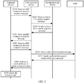
- FIG. 2 is a schematic flowchart of updating an RNA in the 4G and 4.5G mobile communications technologies. As shown in FIG. 2 , the updating an RNA includes the following steps.
- a terminal device in an inactive state sends an RRC connection resume request (RRC Connection Resume Request) message to a first network device (new serving network device).
- RRC Connection Resume Request RRC Connection Resume Request
- the first network device receives the RRC connection resume request message sent by the terminal device in the inactive state.
- the first network device sends a retrieve UE context request (Retrieve UE Context Request) message to a second network device (anchor network device).
- the second network device receives the retrieve UE context request message sent by the first network device.
- the second network device sends a retrieve UE context response (Retrieve UE Context Response) message to the first network device.
- the first network device receives the retrieve UE context response message sent by the second network device.
- the first network device sends an RRC connection resume (RRC Connection Resume) message to the terminal device.
- the terminal device receives the RRC connection resume message sent by the first network device.
- the terminal device sends an RRC connection resume complete (RRC Connection Resume Complete) message to the first network device.
- the first network device receives the RRC connection resume complete message sent by the terminal device. In this case, the terminal device enters a connected state.
- the first network device sends a path switch request (Path Switch Request) message to an AMF.
- the AMF receives the path switch request message sent by the first network device.
- the AMF sends a path switch request acknowledgement (Path Switch Request ACK) message to the first network device.
- the first network device receives the path switch request message sent by the AMF.
- the first network device instructs the terminal device to enter the inactive state.
- the terminal device enters the inactive state.
- state transfer performed by the terminal device twice not only causes redundant signaling overheads, but also wastes power consumption of the terminal device.
- an embodiment of this application provides a method 300 for controlling a status of a terminal device.
- the method 300 includes the following steps.
- a terminal device in an inactive state sends a first request message to a first network device, where the first request message includes first identifier information of the terminal device.
- the first network device receives the first request message sent by the terminal device in the inactive state.
- the terminal device receives a first response message sent by the first network device, where the first response message is used to instruct the terminal device to enter an idle state or enter the inactive state.
- the first network device sends the first response message to the terminal device.
- the terminal device in the inactive state sends a request message to the first network device, the first network device instructs the terminal device to directly enter the idle state or the inactive state, and the terminal device does not need to switch to a connected state in advance, so that signaling overheads can be reduced, and power consumption of the terminal device can be reduced.
- the first request message may further include first cause information, and the first cause information indicates that the first request message is used for RNA update or periodic RNA update.
- FIG. 4 is a schematic flowchart of a method 400 for controlling a status of a terminal device according to an embodiment of this application.
- the method 400 shown in FIG. 4 is applicable to an RNA update scenario.
- a terminal device in an inactive state moves from an original serving radio access network device to a new serving radio access network (NEW Serving RAN, NSR) device, that is, a service range of a first network device, and performs cell reselection.
- NSR new serving radio access network
- the original serving radio access network device is referred to as an anchor radio access network (Anchor RAN, AR) device, namely, a second network device.
- An AMF also participates in interaction.
- the method 400 includes the following steps.
- the terminal device in the inactive state sends a first request message to the first network device.
- the first network device receives the first request message sent by the terminal device in the inactive state.
- the first request message may be a radio resource control RRC connection resume request (RRC Connection Resume Request) message.
- the first identifier information may be inactive state identifier (ID) information allocated by the second network device to the terminal device in the inactive state.
- ID inactive state identifier
- An inactive state identifier of the terminal device is context information that can uniquely identify the terminal in the inactive state in an AR/AC of the terminal in the inactive state.
- the inactive state identifier information of the terminal device may further indicate, to an RAN side, the AR/AC of the terminal device in the inactive state.
- the inactive state identifier information allocated by the second network device to the terminal device may uniquely correspond to a context of the terminal device.
- the first network device may determine, based on the inactive state identifier information provided by the terminal device in the inactive state, that the second network device is the AR of the terminal.
- the inactive state identifier information is access stratum (Access Stratum, AS) ID information.
- the first request message may further include at least one of second network device identifier information, anchor cell identifier information, service type information, slice indicator information, expected state information, and first cause information.
- the first request message may further include the second network device identifier information (for example, AR ID information) or the anchor cell (Anchor Cell, AC) identifier information.
- ID information may be used to assist the first network device (that is, the NSR) in determining the AR or the AC of the terminal device in the inactive state.
- the NSR and the AR are network devices in an inter radio access technology (Inter Radio Access Technologies, Inter-RAT) system
- the NSR cannot determine the AR or the AC of the terminal device in the inactive state based on the ID information of the terminal device. Therefore, the ID information of the AR or the ID information of the AC are required to assist in determining.
- the first request message may further include service type (service type) information.
- the service type information may be used by the NSR to perform RRC layer access control. For example, compared with a mobile broadband (Mobile BroadBand, MBB) service, an ultra-reliable low latency communications (Ultra-Reliable Low latency Communications, URLLC) service has a higher access priority.
- MBB Mobile BroadBand
- URLLC Ultra-Reliable Low latency Communications
- the first request message may further include the slice indicator information, and the slice indicator information is network slice indicator information, whose function is similar to that of the service type information.
- the network slice indicator information is identifier information of a network slice with which the terminal device intends to communicate and/or indicates an AMF corresponding to a network slice with which the terminal device intends to communicate.
- the network slice indicator information may be represented by using at least one of the following parameters:
- the S-NSSAI includes at least slice type/service type (Slice/Service type, SST) information, and optionally, may further include slice differentiator information (Slice Differentiator, SD).
- SST information is used to indicate a network slice behavior, for example, a network slice feature and a service type.
- the SD information is supplementary information of the SST, and if the SST is implemented pointing to a plurality of network slices, the SD may correspond to a unique network slice instance.
- S-NSSAI group information used to instruct to perform grouping according to a particular feature. For example, all network slices of a common AMF that the terminal device can access are used as an S-NSSAI group.
- Temporal ID The temporary identifier information is allocated by the AMF to a terminal device registered with a CN side, and the temporary ID may uniquely point to an AMF.
- the first request message may further include the expected state information.
- the expected state information may indicate that the terminal device expects to enter a connected state, an idle state, or an inactive state after sending the first request message.
- the first request message may further include the first cause information.
- the first cause information may be used to indicate that a cause is update of a radio access network RAN-based notification area RNA.
- the first cause information may alternatively be used to indicate that the cause is periodic update of the RNA, or used to indicate that the cause is transmission of a small data packet, which is to be described in the following embodiments.
- the first network device determines, based on the first request message, to set the terminal device to an idle state or set the terminal device to the inactive state. Specifically, whether to set the terminal device to the idle state or the inactive state may be determined based on the following information. First, if the first request message includes the expected state information, refer to content of the expected state information. Second, determining may be performed based on resource usage. For example, when an NSR resource is insufficient to maintain the terminal device in the inactive state, the terminal device is set to the idle state. For another example, determining may be performed based on a radio resource management (Radio Resource Management, RRM) policy.
- RRM Radio Resource Management
- the terminal device When the terminal device temporarily has no service, and the NSR has sufficient resources (for example, storage resources), the terminal device may be set to the inactive state. Third, determining is performed based on whether the NSR supports the inactive state. When the NSR does not support the inactive state, the NSR can set the terminal device to the idle state only. Fourth, if the AR of the terminal device and the NSR are network devices in the Inter-RAT, the NSR sets the terminal device to the idle state.
- the NSR sets the terminal device to the idle state.
- the first network device sends a third request message to the second network device, where the third request message is used to instruct to request a terminal device context.
- the second network device receives the third request message sent by the first network device.
- the third request message may be a retrieve UE context request (Retrieve UE Context Request) message.
- the retrieve UE context request message may include second cause information.
- the second cause (cause) information may be used to indicate that the cause is RNA update, to be differentiated from transmission of a small data packet, and the like.
- content of the second cause information may be set to "other", "RNA update (update)", or the like.
- the second network device sends a third response message to the second network device, where the third response message is used to feed back the terminal device context.
- the first network device receives the third response message sent by the second network device.
- the third response message may be a retrieve UE context response (Retrieve UE Context Response) message.
- the first network device When determining to set the terminal device to the inactive state, the first network device sends a first response message to the terminal device. Correspondingly, the terminal device receives the first response message sent by the first network device.
- the first response message may be used to instruct the terminal device to perform reconfiguration, for example, reconfiguration on a radio bearer, reconfiguration on a security algorithm, or reconfiguration on an inactive state identifier, and instruct the terminal to enter the inactive state after the reconfiguration is completed.
- the first response message may be an RRC connection resume (RRC Connection Resume) message or an RRC connection reconfiguration (RRC Connection Reconfiguration) message.
- the first response message may instruct, in two manners, the terminal to enter the inactive state after the reconfiguration is completed.
- the first one is an implicit manner:
- the first response message includes only second identifier information allocated by the first network device to the terminal device, for example, the second identifier information may be inactive state identifier information.
- the inactive state identifier information is AS identifier information.
- the terminal device finds that the second identifier information is inconsistent with the inactive state identifier information (the first identifier information) reserved earlier, and considers that the network side still expects the terminal device to anchor in the inactive state. Therefore, the terminal device replaces the first identifier information with the second identifier information.
- the second one is an explicit manner:
- the first response message includes state indicator information, and the state indicator information is used to instruct the terminal device to directly enter the inactive state rather than the connected state.
- the first response message may further include the second identifier information.
- the state indicator information may be suspend indicator (suspend indicator) information.
- an ASN.1 form (pseudocode) of an RNA corresponding to a possible implicit manner may be as follows.
- an ASN.1 form (pseudocode) of an RNA corresponding to a possible explicit manner may be as follows.
- the terminal device performs corresponding configuration based on the first response message in S450, enters the inactive state, and replaces the stored inactive state identifier information of the terminal device with the second identifier information.
- the terminal device sends an RRC connection resume complete (RRC Connection Resume Complete) message to the first network device.
- RRC connection resume complete message may include state acknowledgement information, which indicates that the terminal device has entered the inactive state. It should be noted that, S470 is an optional step, and in some embodiments, this step may not be performed.
- the first network device sends a path switch request (Path Switch Request) message to an AMF.
- the AMF receives the path switch request message sent by the first network device.
- the AMF sends a path switch request acknowledgement (Path Switch Request ACK) message to the first network device.
- the first network device receives the path switch request message sent by the AMF.
- This embodiment of this application describes in detail that during update of the RNA, the terminal device in the inactive state directly enters the inactive state, and does not need to switch to the connected state in advance, so that signaling overheads can be reduced, and power consumption of the terminal device can be reduced.
- FIG. 5 is a schematic flowchart of a method 500 for controlling a status of a terminal device according to another embodiment of this application.
- the method 500 shown in FIG. 5 is applicable to an RNA update scenario, namely, a case in which a first network device determines, based on the first request message, to set the terminal device to an idle state.
- S510 is similar to S410, and details are not described herein again.
- the first network device determines, based on the first request message, to set the terminal device to an idle state or set the terminal device to the inactive state. In this embodiment of this application, only a case in which the terminal device is determined to be set to the idle state is described.
- the first network device When determining to set the terminal device to the idle state, in S530, the first network device sends a second request message to a second network device, where the second request message is used to instruct to delete a terminal device context.
- the second network device receives the second request message sent by the first network device.
- the second request message may be a retrieve UE context release request (Retrieve UE Context Release Request) message.
- the second network device sends a second response message to the first network device, where the second response message is used to feed back a result of deleting the terminal device context.
- the first network device receives the second response message sent by the second network device.
- the second response message may be a retrieve UE context release response (Retrieve UE Context Release Response) message.
- the first network device When determining to set the terminal device to the idle state, the first network device sends a first response message to the terminal device. Correspondingly, the terminal device receives the first response message sent by the first network device. The first response message may be used to instruct the terminal device to enter the idle state. The first response message may be an RRC connection reject (RRC Connection Reject) message.
- RRC connection reject RRC Connection Reject
- the terminal device performs corresponding configuration based on the first response message in S550, and enters the idle state.
- the second network device executes a terminal device context release procedure between the second network device and the AMF. S570.
- the second network device sends a release context request (Release Context Request) message to the AMF.
- the AMF receives the release context request message sent by the second network device.
- the AMF sends a release context response (Release Context Response) message to the second network device.
- the second network device receives the release context response message sent by the AMF.
- This embodiment of this application describes in detail that during update of the RNA, the terminal device in the inactive state directly enters the idle state, and does not need to switch to a connected state in advance, so that signaling overheads can be reduced, and power consumption of the terminal device can be reduced.
- the periodic update of an RNA means that a terminal device still remains in a service range of an original base station (original network device), and is periodic RNA update of a same network device.
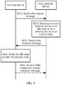
- FIG. 6 is a schematic flowchart of a method 600 for controlling a status of a terminal device according to another embodiment of this application.
- the method 600 shown in FIG. 6 is applicable to a periodic RNA update scenario, and a first network device is an anchor network device and also a serving network device of a terminal device.
- S610 is similar to S410, and details are not described herein again.
- the first network device determines, based on the first request message, to set the terminal device to an idle state or set the terminal device to the inactive state.
- a determining manner is similar to S420, and details are not described herein again.
- the first network device sends a first response message to the terminal device.
- the terminal device receives the first response message sent by the first network device.
- the first response message may be used to instruct the terminal device enter the idle state.
- the first response message may be an RRC connection reject (RRC Connection Reject) message.
- RRC Connection Reject RRC Connection Reject
- the first response message may be used to instruct the terminal device enter the inactive state.
- the first response message may be an RRC connection resume (RRC Connection Resume) message or an RRC connection reconfiguration (RRC Connection Reconfiguration) message.
- the terminal device performs corresponding configuration based on the first response message in S630, and enters the idle state or the inactive state.
- the terminal device may send an RRC connection resume complete (RRC Connection Resume Complete) message to the first network device.
- RRC connection resume complete message may include state acknowledgement information, which indicates that the terminal device has entered the inactive state.
- This embodiment of this application describes in detail that during periodic update of the RNA, the terminal device in the inactive state directly enters the idle state or the inactive state, and does not need to switch to a connected state in advance, so that signaling overheads can be reduced, and power consumption of the terminal device can be reduced.
- An embodiment of this application provides a method for controlling a status of a terminal device.
- the method is performed by a terminal device and includes: sending, by the terminal device in an inactive state, a first request message to a first network device, where the first request message includes first identifier information of the terminal device; and receiving, by the terminal device, a first response message sent by the first network device, where the first response message is used to instruct the terminal device to enter the inactive state to transmit a small data packet.
- an embodiment of this application further provides a method for controlling a status of a terminal device.
- the method is performed by a first network device and includes: receiving, by the first network device, a first request message sent by a terminal device in an inactive state, where the first request message includes first identifier information of the terminal device; and sending, by the first network device, a first response message to the terminal device, where the first response message is used to instruct the terminal device to enter the inactive state to transmit a small data packet.
- the first identifier information is identifier information allocated by a second network device for the terminal device in the inactive state.
- the first response message when the first response message is used to instruct the terminal device to enter the inactive state, the first response message includes second identifier information allocated by the first network device to the terminal device.
- the first response message when used to instruct the terminal device to enter the inactive state, the first response message includes state indicator information, and the state indicator information is used to instruct the terminal device to enter the inactive state rather than a connected state.
- the first request message further includes at least one of second network device identifier information, anchor cell identifier information, service type information, slice indicator information, expected state information, and first cause information.
- the first cause information is used to indicate that a cause is transmission of a small data packet.
- the method before the sending, by the first network device, a first response message to the terminal device, the method further includes: determining, by the first network device based on the first request message, to set the terminal device to an idle state or set the terminal device to the inactive state.
- the third request message includes second cause information, and the second cause information is used to indicate that a cause is transmission of a small data packet; and the third response message includes an entire or a partial context of the terminal device.
- the third request message includes second cause information
- the second cause information may further include bearer indicator information corresponding to the small data packet, where the bearer indicator information indicates a bearer corresponding to the small data packet.
- FIG. 7 is a schematic flowchart of a method 700 for controlling a status of a terminal device according to an embodiment of this application.
- a terminal device in an inactive state moves from an original serving radio access network device to a new serving radio access network (NEW Serving RAN, NSR) device, that is, a service range of a first network device, and performs cell reselection.
- NSR new serving radio access network
- the original serving radio access network device is referred to as an anchor radio access network (Anchor RAN, AR) device, namely, a second network device.
- An AMF also participates in interaction.
- the method 700 includes the following steps.
- S710 is similar to S410, and details are not described herein again. A difference is that in S710, a small data packet can also be sent along with the first request message.
- the first request message may include first cause information.
- the first cause information is used to indicate that a cause is transmission of a small data packet.
- the first network device determines, based on the first request message, that the terminal device may transmit a small data packet in the inactive state, and still remains in the inactive state after the small data packet is transmitted.
- the first network device sends a third request message to the second network device, where the third request message is used to instruct to request a terminal device context.
- the second network device receives the third request message sent by the first network device.
- the third request message may be a retrieve UE context request (Retrieve UE Context Request) message.
- the retrieve UE context request message may include second cause information.
- the second cause (cause) information may be used to indicate that the cause is transmission of a small data packet.
- the second cause information may further include bearer indicator information corresponding to the small data packet, where the bearer indicator information indicates a bearer corresponding to the small data packet.
- the second network device sends a third response message to the first network device, where the third response message is used to feed back the terminal device context.
- the first network device receives the third response message sent by the second network device.
- the third response message may be a retrieve UE context response (Retrieve UE Context Release Response) message.
- the third response message may include an entire context of the terminal device.
- the third response message may alternatively include a partial context of the terminal device.
- the partial context may be determined by the second network device based on the bearer indicator information corresponding to the small data packet.
- the partial context of the terminal device may include, protocol stack configuration information of a bearer corresponding to the small data packet, and/or protocol stack status information (for example, a current radio link control (Radio Link Control, RLC) frame number) of a bearer corresponding to the small data packet.
- protocol stack status information for example, a current radio link control (Radio Link Control, RLC) frame number
- the first network device sends a first response message to the terminal device.
- the terminal device receives the first response message sent by the first network device.
- the first response message may be used to instruct the terminal device to enter the inactive state.
- the first response message may be an RRC connection resume (RRC Connection Resume) message or an RRC connection reconfiguration (RRC Connection Reconfiguration) message.
- S770 to S795 are similar to S460 to S490, and details are not described herein again. It should be noted that, S780 to S795 are optional steps, and in some embodiments, these steps may not be performed.
- This embodiment of this application describes in detail that when the small data packet is transmitted, the terminal device in the inactive state directly enters the inactive state, and does not need to switch to a connected state in advance, so that signaling overheads can be reduced, and power consumption of the terminal device can be reduced.
- sequence numbers of the foregoing processes do not mean execution sequences in various embodiments of this application.
- the execution sequences of the processes should be determined according to functions and internal logic of the processes, and should not be construed as any limitation on the implementation processes of the embodiments of this application.
- FIG. 8 is a schematic block diagram of a terminal device 800 according to an embodiment of this application.
- the terminal device 800 may include: a sending module 810 and a receiving module 820.
- the sending module 810 is configured to send a first request message to a first network device, where the first request message includes first identifier information of the terminal device.
- the receiving module 820 is configured to receive a first response message sent by the first network device, where the first response message is used to instruct the terminal device to enter an idle state or enter an inactive state.
- the terminal device When the terminal device in this embodiment of this application is in the inactive state, the terminal device sends a request message to the first network device, the first network device instructs the terminal device to directly enter the idle state or the inactive state, and the terminal device does not need to switch to a connected state in advance, so that signaling overheads can be reduced, and power consumption of the terminal device can be reduced.
- the first identifier information is inactive state identifier information allocated by a second network device for the terminal device in the inactive state.
- the first response message when the first response message is used to instruct the terminal device to enter the inactive state, the first response message includes second identifier information allocated by the first network device to the terminal device.
- the first response message when used to instruct the terminal device to enter the inactive state, the first response message includes state indicator information, and the state indicator information is used to instruct the terminal device to enter the inactive state rather than a connected state.
- the first request message further includes at least one of second network device identifier information, anchor cell identifier information, service type information, slice indicator information, expected state information, and first cause information.
- the first cause information is used to indicate that a cause is update of a radio access network RAN-based notification area RNA.
- the first cause information is used to indicate that the cause is periodic update of the RNA.
- a terminal device 900 may include a processor 910, a transceiver 920, and a memory 930.
- the memory 930 may be configured to store code executed by the processor 910, to control the transceiver 920 to perform a corresponding function.
- the components in the terminal device 900 may communicate with each other by using an internally connected channel, to transfer a control and/or data signal.
- the terminal device 900 shown in FIG. 9 or the terminal device 800 shown in FIG. 8 can implement the processes in the foregoing method embodiments. To avoid repetition, details are not described herein again.
- a terminal device configured to perform the method 700 may also have a similar structure as described above.
- the terminal device includes: a sending module, configured to send a first request message to a first network device, where the first request message includes first identifier information of the terminal device; and a receiving module, configured to receive a first response message sent by the first network device, where the first response message is used to instruct the terminal device to enter an inactive state to transmit a small data packet.
- the structure of the terminal device configured to perform the method 700 is not described herein again.
- FIG. 10 is a schematic block diagram of a first network device 1000 according to an embodiment of this application. As shown in FIG. 10 , the first network device 1000 may include the following modules:
- the first network device in this embodiment of this application receives a request message sent by the terminal device in the inactive state, the first network device instructs the terminal device to directly enter the idle state or enter the inactive state, and the terminal device does not need to switch to a connected state in advance, so that signaling overheads can be reduced, and power consumption of the terminal device can be reduced.
- the first identifier information is inactive state identifier information allocated by a second network device for the terminal device in the inactive state.
- the first response message when the first response message is used to instruct the terminal device to enter the inactive state, the first response message includes second identifier information allocated by the first network device to the terminal device.
- the first response message when used to instruct the terminal device to enter the inactive state, the first response message includes state indicator information, and the state indicator information is used to instruct the terminal device to enter the inactive state rather than the connected state.
- the first request message further includes at least one of second network device identifier information, anchor cell identifier information, service type information, slice indicator information, expected state information, and first cause information.
- the first cause information is used to indicate that a cause is update of a radio access network RAN-based notification area RNA.
- the first cause information is used to indicate that the cause is periodic update of the RNA.
- the first network device further includes a processing module 1030, configured to: before the sending module sends the first response message to the terminal device, determine, based on the first request message, to set the terminal device to the idle state or set the terminal device to the inactive state.
- a processing module 1030 configured to: before the sending module sends the first response message to the terminal device, determine, based on the first request message, to set the terminal device to the idle state or set the terminal device to the inactive state.
- the sending module 1020 is further configured to: when the processing module 1030 determines to set the terminal device to the idle state, send a second request message to the second network device, where the second request message is used to instruct to delete a terminal device context.
- the receiving module 1010 is further configured to receive a second response message sent by the second network device, where the second response message is used to feed back a result of deleting the terminal device context.
- the sending module 1020 is further configured to: when the processing module 1030 determines to set the terminal device to the inactive state, send a third request message to the second network device, where the third request message is used to instruct to request a terminal device context; and the receiving module 1010 is further configured to receive a third response message sent by the second network device, where the third response message is used to feed back the terminal device context.
- the receiving unit 1010 and the sending unit 1020 may be implemented by a transceiver, and the processing module 1030 may be implemented by a processor.
- the first network device 1100 may include a processor 1110, a transceiver 1120, and a memory 1130.
- the memory 1130 may be configured to store code executed by the processor 1110, to control the transceiver 1120 to perform a corresponding function.
- the components in the first network device 1100 may communicate with each other by using an internally connected channel, to transfer a control and/or data signal.
- the first network device 1100 shown in FIG. 11 or the first network device 1000 shown in FIG. 10 can implement the processes implemented in the foregoing method embodiments. To avoid repetition, details are not described herein again.
- a first network device configured to perform the method 700 may also have a similar structure as described above.
- the first network device includes: a receiving module, configured to receive a first request message sent by a terminal device in an inactive state, where the first request message includes first identifier information of the terminal device; and a sending module, configured to send a first response message to the terminal device, where the first response message is used to instruct the terminal device to enter the inactive state to transmit a small data packet.
- the structure of the first network device configured to perform the method 700 is not described herein again.
- the second network device in the embodiments of this application may also have a structure similar to those of the first network devices shown in FIG. 10 and FIG. 11 , and details are not described herein again.
- the disclosed system, apparatus, and method may be implemented in other manners.
- the described apparatus embodiments are merely examples.
- the unit division is merely logical function division and may be other division in actual implementation.
- a plurality of units or components may be combined or integrated into another system, or some features may be ignored or not performed.
- the displayed or discussed mutual couplings or direct couplings or communication connections may be implemented by using some interfaces.
- the indirect couplings or communication connections between the apparatuses or units may be implemented in electronic, mechanical, or other forms.
- the units described as separate parts may or may not be physically separate, and parts displayed as units may or may not be physical units, may be located in one position, or may be distributed on a plurality of network units. Some or all of the units may be selected based on actual requirements to achieve the objectives of the solutions of the embodiments.
- the functions When the functions are implemented in the form of a software functional unit and sold or used as an independent product, the functions may be stored in a computer readable storage medium. Based on such an understanding, the technical solutions of this application essentially, or the part contributing to the prior art, or some of the technical solutions may be implemented in a form of a software product.
- the software product is stored in a storage medium, and includes several instructions for instructing a computer device (which may be a personal computer, a server, or a network device) to perform all or some of the steps of the methods described in the embodiments of this application.
- the foregoing storage medium includes: any medium that can store program code, such as a USB flash drive, a removable hard disk, a read-only memory (Read-Only Memory, ROM), a random access memory (Random Access Memory, RAM), a magnetic disk, or an optical disc.
- program code such as a USB flash drive, a removable hard disk, a read-only memory (Read-Only Memory, ROM), a random access memory (Random Access Memory, RAM), a magnetic disk, or an optical disc.
Landscapes
- Engineering & Computer Science (AREA)
- Computer Networks & Wireless Communication (AREA)
- Signal Processing (AREA)
- Databases & Information Systems (AREA)
- Mobile Radio Communication Systems (AREA)
Applications Claiming Priority (2)
| Application Number | Priority Date | Filing Date | Title |
|---|---|---|---|
| CN201710184667.5A CN108632810B (zh) | 2017-03-24 | 2017-03-24 | 控制终端设备状态的方法、终端设备和网络设备 |
| PCT/CN2018/080230 WO2018171724A1 (fr) | 2017-03-24 | 2018-03-23 | Procédé de contrôle d'états de dispositif terminal, dispositif terminal, et dispositif de réseau |
Publications (3)
| Publication Number | Publication Date |
|---|---|
| EP3573356A1 true EP3573356A1 (fr) | 2019-11-27 |
| EP3573356A4 EP3573356A4 (fr) | 2019-12-04 |
| EP3573356B1 EP3573356B1 (fr) | 2021-07-28 |
Family
ID=63584954
Family Applications (1)
| Application Number | Title | Priority Date | Filing Date |
|---|---|---|---|
| EP18770505.8A Active EP3573356B1 (fr) | 2017-03-24 | 2018-03-23 | Procédé de contrôle d'états de dispositif terminal, dispositif terminal, et dispositif de réseau |
Country Status (4)
| Country | Link |
|---|---|
| US (1) | US20200022083A1 (fr) |
| EP (1) | EP3573356B1 (fr) |
| CN (1) | CN108632810B (fr) |
| WO (1) | WO2018171724A1 (fr) |
Cited By (2)
| Publication number | Priority date | Publication date | Assignee | Title |
|---|---|---|---|---|
| EP3614735A4 (fr) * | 2017-05-05 | 2020-05-06 | Huawei Technologies Co., Ltd. | Procédé de transmission de données, dispositif et système associés |
| CN114071801A (zh) * | 2020-07-29 | 2022-02-18 | 华为技术有限公司 | 一种终端设备的状态指示方法及通信装置 |
Families Citing this family (19)
| Publication number | Priority date | Publication date | Assignee | Title |
|---|---|---|---|---|
| EP3982695B1 (fr) * | 2017-09-28 | 2025-07-02 | Guangdong Oppo Mobile Telecommunications Corp., Ltd. | Procédé de communication sans fil et dispositif terminal |
| CN111819879B (zh) * | 2018-03-26 | 2024-04-26 | 瑞典爱立信有限公司 | 在rrc非活动状态下暂停/恢复测量 |
| CN112514522B (zh) | 2018-05-07 | 2024-07-23 | 瑞典爱立信有限公司 | 用于恢复时挂起不活动和挂起时恢复不活动的方法 |
| WO2020164025A1 (fr) * | 2019-02-13 | 2020-08-20 | Oppo广东移动通信有限公司 | Procédé et dispositif de transfert d'état |
| US12022550B2 (en) * | 2019-03-15 | 2024-06-25 | Lg Electronics Inc. | Small data transmission without path switch procedure |
| WO2021030928A1 (fr) | 2019-08-16 | 2021-02-25 | Oppo广东移动通信有限公司 | Procédé de commande de mesures, dispositif électronique et support de stockage |
| WO2021097811A1 (fr) * | 2019-11-22 | 2021-05-27 | Lenovo (Beijing) Limited | Procédé et appareil de mise à jour de zone de notification basée sur un réseau d'accès radio |
| WO2021147030A1 (fr) * | 2020-01-22 | 2021-07-29 | Nec Corporation | Procédés, dispositifs, et support de communication |
| EP4156846A4 (fr) * | 2020-06-19 | 2023-07-05 | Guangdong Oppo Mobile Telecommunications Corp., Ltd. | Procédé de transmission de données et dispositif de réseau |
| EP4165901B1 (fr) | 2020-07-23 | 2026-04-15 | ZTE Corporation | Acheminement de données pour un équipement utilisateur avec transmission de données |
| CN112272389B (zh) * | 2020-10-22 | 2023-07-21 | 广东邮电职业技术学院 | 终端管理的方法、终端管理系统、计算机设备及存储介质 |
| WO2022094810A1 (fr) * | 2020-11-04 | 2022-05-12 | Oppo广东移动通信有限公司 | Procédé et appareil de transition d'état de rrc, et équipement terminal |
| WO2022183362A1 (fr) * | 2021-03-02 | 2022-09-09 | Oppo广东移动通信有限公司 | Procédé communication, dispositif, et support de stockage |
| CN115150894A (zh) * | 2021-03-31 | 2022-10-04 | 华为技术有限公司 | 通信方法及装置 |
| CN115484615A (zh) * | 2021-05-31 | 2022-12-16 | 华为技术有限公司 | 通信方法及通信装置 |
| CN113596966A (zh) * | 2021-07-09 | 2021-11-02 | Oppo广东移动通信有限公司 | 一种功耗控制方法、终端设备、网络设备及存储介质 |
| EP4331262A4 (fr) | 2021-09-17 | 2025-03-05 | Radisys India Private Limited | Systèmes et procédés de récupération d'informations ran |
| CN117651317A (zh) * | 2022-09-05 | 2024-03-05 | 华为技术有限公司 | 一种通信的方法和通信装置 |
| CN117561759A (zh) * | 2023-09-27 | 2024-02-13 | 北京小米移动软件有限公司 | 信息传输方法及装置、存储介质 |
Family Cites Families (6)
| Publication number | Priority date | Publication date | Assignee | Title |
|---|---|---|---|---|
| CN100576954C (zh) * | 2007-09-24 | 2009-12-30 | 大唐移动通信设备有限公司 | 基于空闲状态用户终端的位置移动能力确定方法及装置 |
| CN101729327B (zh) * | 2008-10-17 | 2013-06-12 | 中兴通讯股份有限公司 | 接入网关的选择方法以及自动配置服务器 |
| CN102724650A (zh) * | 2011-03-31 | 2012-10-10 | 中兴通讯股份有限公司 | 一种位置管理方法及系统 |
| CN104284321B (zh) * | 2013-07-08 | 2018-09-21 | 华为终端(东莞)有限公司 | 一种路径切换的方法、设备和用户设备 |
| WO2015085273A1 (fr) * | 2013-12-06 | 2015-06-11 | Interdigital Patent Holdings, Inc. | Connectivité en couches dans des systèmes sans fil |
| CN105898894B (zh) * | 2016-05-13 | 2021-08-20 | 华为技术有限公司 | Rrc状态的控制方法和装置 |
-
2017
- 2017-03-24 CN CN201710184667.5A patent/CN108632810B/zh active Active
-
2018
- 2018-03-23 WO PCT/CN2018/080230 patent/WO2018171724A1/fr not_active Ceased
- 2018-03-23 EP EP18770505.8A patent/EP3573356B1/fr active Active
-
2019
- 2019-09-24 US US16/579,850 patent/US20200022083A1/en not_active Abandoned
Cited By (4)
| Publication number | Priority date | Publication date | Assignee | Title |
|---|---|---|---|---|
| EP3614735A4 (fr) * | 2017-05-05 | 2020-05-06 | Huawei Technologies Co., Ltd. | Procédé de transmission de données, dispositif et système associés |
| US11368882B2 (en) | 2017-05-05 | 2022-06-21 | Huawei Technologies Co., Ltd. | Data transmission method, and related device and system |
| CN114071801A (zh) * | 2020-07-29 | 2022-02-18 | 华为技术有限公司 | 一种终端设备的状态指示方法及通信装置 |
| CN114071801B (zh) * | 2020-07-29 | 2024-01-16 | 华为技术有限公司 | 一种终端设备的状态指示方法及通信装置 |
Also Published As
| Publication number | Publication date |
|---|---|
| US20200022083A1 (en) | 2020-01-16 |
| CN108632810B (zh) | 2021-08-20 |
| EP3573356A4 (fr) | 2019-12-04 |
| CN108632810A (zh) | 2018-10-09 |
| WO2018171724A1 (fr) | 2018-09-27 |
| EP3573356B1 (fr) | 2021-07-28 |
Similar Documents
| Publication | Publication Date | Title |
|---|---|---|
| EP3573356B1 (fr) | Procédé de contrôle d'états de dispositif terminal, dispositif terminal, et dispositif de réseau | |
| CN113475109B (zh) | 随着rrc恢复完成之类的消息的早期测量报告 | |
| EP3675579B1 (fr) | Procédés de programmation de données, appareils et supports lisibles par ordinateur | |
| US12335741B2 (en) | Network slice redirection method and apparatus | |
| CN108605269B (zh) | 一种会话管理方法及装置 | |
| EP3017636B1 (fr) | Mise en mémoire tampon de mode repos dans un plan utilisateur dans une architecture de réseau définie par logiciel | |
| EP3138357B1 (fr) | Procédé et appareil de migration de station de base virtuelle dans un ensemble bbu | |
| EP3764693A1 (fr) | Procédé et appareil de transfert, et support de stockage informatique | |
| WO2020057328A1 (fr) | Procédé et appareil de communication | |
| JP2024538509A (ja) | 通信方法 | |
| CN111556589B (zh) | 通信的方法、终端和接入网设备 | |
| WO2018019001A1 (fr) | Procédé et appareil de changement d'état d'un terminal | |
| CN107046714B (zh) | 一种数据传输方法、装置和系统 | |
| WO2018170626A1 (fr) | Procédé de récupération de connexion, entité de fonction de gestion d'accès et de mobilité, et équipement utilisateur | |
| KR20190099308A (ko) | 통신 방법, 액세스 네트워크 장치, 및 단말기 | |
| CN109314896B (zh) | 小区切换方法、装置及可读存储介质 | |
| WO2018127030A1 (fr) | Procédé et dispositif de notification d'informations concernant une zone de notification basée ran | |
| CN108353380A (zh) | 蜂窝通信系统中的数据路由 | |
| CN117641580A (zh) | 通信方法、终端设备和接入网设备 | |
| WO2018028336A1 (fr) | Procédé et dispositif d'accès aléatoire | |
| CN114363975B (zh) | 数据通信方法、装置、电子设备及存储介质 | |
| CN119586210B (zh) | 无线网络中用于scg安全性的方法、设备和系统 | |
| KR101467795B1 (ko) | 단말 능력을 관리하는 방법 | |
| CN114071604B (zh) | 数据传输方法、设备、装置及存储介质 | |
| CN114128394B (zh) | 资源处理方法及装置 |
Legal Events
| Date | Code | Title | Description |
|---|---|---|---|
| STAA | Information on the status of an ep patent application or granted ep patent |
Free format text: STATUS: THE INTERNATIONAL PUBLICATION HAS BEEN MADE |
|
| PUAI | Public reference made under article 153(3) epc to a published international application that has entered the european phase |
Free format text: ORIGINAL CODE: 0009012 |
|
| STAA | Information on the status of an ep patent application or granted ep patent |
Free format text: STATUS: REQUEST FOR EXAMINATION WAS MADE |
|
| 17P | Request for examination filed |
Effective date: 20190821 |
|
| AK | Designated contracting states |
Kind code of ref document: A1 Designated state(s): AL AT BE BG CH CY CZ DE DK EE ES FI FR GB GR HR HU IE IS IT LI LT LU LV MC MK MT NL NO PL PT RO RS SE SI SK SM TR |
|
| AX | Request for extension of the european patent |
Extension state: BA ME |
|
| A4 | Supplementary search report drawn up and despatched |
Effective date: 20191107 |
|
| RIC1 | Information provided on ipc code assigned before grant |
Ipc: H04W 76/25 20180101ALI20191031BHEP Ipc: H04W 76/27 20180101ALI20191031BHEP Ipc: H04W 8/04 20090101AFI20191031BHEP |
|
| DAV | Request for validation of the european patent (deleted) | ||
| DAX | Request for extension of the european patent (deleted) | ||
| GRAP | Despatch of communication of intention to grant a patent |
Free format text: ORIGINAL CODE: EPIDOSNIGR1 |
|
| STAA | Information on the status of an ep patent application or granted ep patent |
Free format text: STATUS: GRANT OF PATENT IS INTENDED |
|
| INTG | Intention to grant announced |
Effective date: 20210316 |
|
| GRAS | Grant fee paid |
Free format text: ORIGINAL CODE: EPIDOSNIGR3 |
|
| GRAA | (expected) grant |
Free format text: ORIGINAL CODE: 0009210 |
|
| STAA | Information on the status of an ep patent application or granted ep patent |
Free format text: STATUS: THE PATENT HAS BEEN GRANTED |
|
| AK | Designated contracting states |
Kind code of ref document: B1 Designated state(s): AL AT BE BG CH CY CZ DE DK EE ES FI FR GB GR HR HU IE IS IT LI LT LU LV MC MK MT NL NO PL PT RO RS SE SI SK SM TR |
|
| REG | Reference to a national code |
Ref country code: GB Ref legal event code: FG4D |
|
| REG | Reference to a national code |
Ref country code: CH Ref legal event code: EP |
|
| REG | Reference to a national code |
Ref country code: AT Ref legal event code: REF Ref document number: 1415850 Country of ref document: AT Kind code of ref document: T Effective date: 20210815 |
|
| REG | Reference to a national code |
Ref country code: IE Ref legal event code: FG4D |
|
| REG | Reference to a national code |
Ref country code: DE Ref legal event code: R096 Ref document number: 602018020907 Country of ref document: DE |
|
| REG | Reference to a national code |
Ref country code: LT Ref legal event code: MG9D |
|
| REG | Reference to a national code |
Ref country code: NL Ref legal event code: MP Effective date: 20210728 |
|
| REG | Reference to a national code |
Ref country code: AT Ref legal event code: MK05 Ref document number: 1415850 Country of ref document: AT Kind code of ref document: T Effective date: 20210728 |
|
| PG25 | Lapsed in a contracting state [announced via postgrant information from national office to epo] |
Ref country code: RS Free format text: LAPSE BECAUSE OF FAILURE TO SUBMIT A TRANSLATION OF THE DESCRIPTION OR TO PAY THE FEE WITHIN THE PRESCRIBED TIME-LIMIT Effective date: 20210728 Ref country code: SE Free format text: LAPSE BECAUSE OF FAILURE TO SUBMIT A TRANSLATION OF THE DESCRIPTION OR TO PAY THE FEE WITHIN THE PRESCRIBED TIME-LIMIT Effective date: 20210728 Ref country code: HR Free format text: LAPSE BECAUSE OF FAILURE TO SUBMIT A TRANSLATION OF THE DESCRIPTION OR TO PAY THE FEE WITHIN THE PRESCRIBED TIME-LIMIT Effective date: 20210728 Ref country code: ES Free format text: LAPSE BECAUSE OF FAILURE TO SUBMIT A TRANSLATION OF THE DESCRIPTION OR TO PAY THE FEE WITHIN THE PRESCRIBED TIME-LIMIT Effective date: 20210728 Ref country code: FI Free format text: LAPSE BECAUSE OF FAILURE TO SUBMIT A TRANSLATION OF THE DESCRIPTION OR TO PAY THE FEE WITHIN THE PRESCRIBED TIME-LIMIT Effective date: 20210728 Ref country code: NO Free format text: LAPSE BECAUSE OF FAILURE TO SUBMIT A TRANSLATION OF THE DESCRIPTION OR TO PAY THE FEE WITHIN THE PRESCRIBED TIME-LIMIT Effective date: 20211028 Ref country code: PT Free format text: LAPSE BECAUSE OF FAILURE TO SUBMIT A TRANSLATION OF THE DESCRIPTION OR TO PAY THE FEE WITHIN THE PRESCRIBED TIME-LIMIT Effective date: 20211129 Ref country code: NL Free format text: LAPSE BECAUSE OF FAILURE TO SUBMIT A TRANSLATION OF THE DESCRIPTION OR TO PAY THE FEE WITHIN THE PRESCRIBED TIME-LIMIT Effective date: 20210728 Ref country code: BG Free format text: LAPSE BECAUSE OF FAILURE TO SUBMIT A TRANSLATION OF THE DESCRIPTION OR TO PAY THE FEE WITHIN THE PRESCRIBED TIME-LIMIT Effective date: 20211028 Ref country code: AT Free format text: LAPSE BECAUSE OF FAILURE TO SUBMIT A TRANSLATION OF THE DESCRIPTION OR TO PAY THE FEE WITHIN THE PRESCRIBED TIME-LIMIT Effective date: 20210728 Ref country code: LT Free format text: LAPSE BECAUSE OF FAILURE TO SUBMIT A TRANSLATION OF THE DESCRIPTION OR TO PAY THE FEE WITHIN THE PRESCRIBED TIME-LIMIT Effective date: 20210728 |
|
| PG25 | Lapsed in a contracting state [announced via postgrant information from national office to epo] |
Ref country code: PL Free format text: LAPSE BECAUSE OF FAILURE TO SUBMIT A TRANSLATION OF THE DESCRIPTION OR TO PAY THE FEE WITHIN THE PRESCRIBED TIME-LIMIT Effective date: 20210728 Ref country code: LV Free format text: LAPSE BECAUSE OF FAILURE TO SUBMIT A TRANSLATION OF THE DESCRIPTION OR TO PAY THE FEE WITHIN THE PRESCRIBED TIME-LIMIT Effective date: 20210728 Ref country code: GR Free format text: LAPSE BECAUSE OF FAILURE TO SUBMIT A TRANSLATION OF THE DESCRIPTION OR TO PAY THE FEE WITHIN THE PRESCRIBED TIME-LIMIT Effective date: 20211029 |
|
| PG25 | Lapsed in a contracting state [announced via postgrant information from national office to epo] |
Ref country code: DK Free format text: LAPSE BECAUSE OF FAILURE TO SUBMIT A TRANSLATION OF THE DESCRIPTION OR TO PAY THE FEE WITHIN THE PRESCRIBED TIME-LIMIT Effective date: 20210728 |
|
| REG | Reference to a national code |
Ref country code: DE Ref legal event code: R097 Ref document number: 602018020907 Country of ref document: DE |
|
| PG25 | Lapsed in a contracting state [announced via postgrant information from national office to epo] |
Ref country code: SM Free format text: LAPSE BECAUSE OF FAILURE TO SUBMIT A TRANSLATION OF THE DESCRIPTION OR TO PAY THE FEE WITHIN THE PRESCRIBED TIME-LIMIT Effective date: 20210728 Ref country code: SK Free format text: LAPSE BECAUSE OF FAILURE TO SUBMIT A TRANSLATION OF THE DESCRIPTION OR TO PAY THE FEE WITHIN THE PRESCRIBED TIME-LIMIT Effective date: 20210728 Ref country code: RO Free format text: LAPSE BECAUSE OF FAILURE TO SUBMIT A TRANSLATION OF THE DESCRIPTION OR TO PAY THE FEE WITHIN THE PRESCRIBED TIME-LIMIT Effective date: 20210728 Ref country code: EE Free format text: LAPSE BECAUSE OF FAILURE TO SUBMIT A TRANSLATION OF THE DESCRIPTION OR TO PAY THE FEE WITHIN THE PRESCRIBED TIME-LIMIT Effective date: 20210728 Ref country code: CZ Free format text: LAPSE BECAUSE OF FAILURE TO SUBMIT A TRANSLATION OF THE DESCRIPTION OR TO PAY THE FEE WITHIN THE PRESCRIBED TIME-LIMIT Effective date: 20210728 Ref country code: AL Free format text: LAPSE BECAUSE OF FAILURE TO SUBMIT A TRANSLATION OF THE DESCRIPTION OR TO PAY THE FEE WITHIN THE PRESCRIBED TIME-LIMIT Effective date: 20210728 |
|
| PLBE | No opposition filed within time limit |
Free format text: ORIGINAL CODE: 0009261 |
|
| STAA | Information on the status of an ep patent application or granted ep patent |
Free format text: STATUS: NO OPPOSITION FILED WITHIN TIME LIMIT |
|
| 26N | No opposition filed |
Effective date: 20220429 |
|
| PG25 | Lapsed in a contracting state [announced via postgrant information from national office to epo] |
Ref country code: IT Free format text: LAPSE BECAUSE OF FAILURE TO SUBMIT A TRANSLATION OF THE DESCRIPTION OR TO PAY THE FEE WITHIN THE PRESCRIBED TIME-LIMIT Effective date: 20210728 |
|
| PG25 | Lapsed in a contracting state [announced via postgrant information from national office to epo] |
Ref country code: MC Free format text: LAPSE BECAUSE OF FAILURE TO SUBMIT A TRANSLATION OF THE DESCRIPTION OR TO PAY THE FEE WITHIN THE PRESCRIBED TIME-LIMIT Effective date: 20210728 |
|
| REG | Reference to a national code |
Ref country code: CH Ref legal event code: PL |
|
| GBPC | Gb: european patent ceased through non-payment of renewal fee |
Effective date: 20220323 |
|
| REG | Reference to a national code |
Ref country code: BE Ref legal event code: MM Effective date: 20220331 |
|
| PG25 | Lapsed in a contracting state [announced via postgrant information from national office to epo] |
Ref country code: LU Free format text: LAPSE BECAUSE OF NON-PAYMENT OF DUE FEES Effective date: 20220323 Ref country code: LI Free format text: LAPSE BECAUSE OF NON-PAYMENT OF DUE FEES Effective date: 20220331 Ref country code: IE Free format text: LAPSE BECAUSE OF NON-PAYMENT OF DUE FEES Effective date: 20220323 Ref country code: GB Free format text: LAPSE BECAUSE OF NON-PAYMENT OF DUE FEES Effective date: 20220323 Ref country code: FR Free format text: LAPSE BECAUSE OF NON-PAYMENT OF DUE FEES Effective date: 20220331 Ref country code: CH Free format text: LAPSE BECAUSE OF NON-PAYMENT OF DUE FEES Effective date: 20220331 |
|
| PG25 | Lapsed in a contracting state [announced via postgrant information from national office to epo] |
Ref country code: BE Free format text: LAPSE BECAUSE OF NON-PAYMENT OF DUE FEES Effective date: 20220331 |
|
| P01 | Opt-out of the competence of the unified patent court (upc) registered |
Effective date: 20230524 |
|
| PG25 | Lapsed in a contracting state [announced via postgrant information from national office to epo] |
Ref country code: MK Free format text: LAPSE BECAUSE OF FAILURE TO SUBMIT A TRANSLATION OF THE DESCRIPTION OR TO PAY THE FEE WITHIN THE PRESCRIBED TIME-LIMIT Effective date: 20210728 Ref country code: CY Free format text: LAPSE BECAUSE OF FAILURE TO SUBMIT A TRANSLATION OF THE DESCRIPTION OR TO PAY THE FEE WITHIN THE PRESCRIBED TIME-LIMIT Effective date: 20210728 |
|
| PG25 | Lapsed in a contracting state [announced via postgrant information from national office to epo] |
Ref country code: HU Free format text: LAPSE BECAUSE OF FAILURE TO SUBMIT A TRANSLATION OF THE DESCRIPTION OR TO PAY THE FEE WITHIN THE PRESCRIBED TIME-LIMIT; INVALID AB INITIO Effective date: 20180323 |
|
| PG25 | Lapsed in a contracting state [announced via postgrant information from national office to epo] |
Ref country code: MT Free format text: LAPSE BECAUSE OF FAILURE TO SUBMIT A TRANSLATION OF THE DESCRIPTION OR TO PAY THE FEE WITHIN THE PRESCRIBED TIME-LIMIT Effective date: 20210728 |
|
| PG25 | Lapsed in a contracting state [announced via postgrant information from national office to epo] |
Ref country code: TR Free format text: LAPSE BECAUSE OF FAILURE TO SUBMIT A TRANSLATION OF THE DESCRIPTION OR TO PAY THE FEE WITHIN THE PRESCRIBED TIME-LIMIT Effective date: 20210728 |
|
| PGFP | Annual fee paid to national office [announced via postgrant information from national office to epo] |
Ref country code: DE Payment date: 20260204 Year of fee payment: 9 |