EP3573883B1 - Soutien lombaire comprenant un moyen de fixation, selle pourvue d'un soutien lombaire et appareil pourvu de cette selle - Google Patents
Soutien lombaire comprenant un moyen de fixation, selle pourvue d'un soutien lombaire et appareil pourvu de cette selle Download PDFInfo
- Publication number
- EP3573883B1 EP3573883B1 EP18752413.7A EP18752413A EP3573883B1 EP 3573883 B1 EP3573883 B1 EP 3573883B1 EP 18752413 A EP18752413 A EP 18752413A EP 3573883 B1 EP3573883 B1 EP 3573883B1
- Authority
- EP
- European Patent Office
- Prior art keywords
- pedal
- saddle
- backrest
- driven device
- base body
- Prior art date
- Legal status (The legal status is an assumption and is not a legal conclusion. Google has not performed a legal analysis and makes no representation as to the accuracy of the status listed.)
- Active
Links
Images



Classifications
-
- B—PERFORMING OPERATIONS; TRANSPORTING
- B62—LAND VEHICLES FOR TRAVELLING OTHERWISE THAN ON RAILS
- B62J—CYCLE SADDLES OR SEATS; AUXILIARY DEVICES OR ACCESSORIES SPECIALLY ADAPTED TO CYCLES AND NOT OTHERWISE PROVIDED FOR, e.g. ARTICLE CARRIERS OR CYCLE PROTECTORS
- B62J1/00—Saddles or other seats for cycles; Arrangement thereof; Component parts
- B62J1/28—Other additional equipment, e.g. back-rests for children
-
- B—PERFORMING OPERATIONS; TRANSPORTING
- B62—LAND VEHICLES FOR TRAVELLING OTHERWISE THAN ON RAILS
- B62J—CYCLE SADDLES OR SEATS; AUXILIARY DEVICES OR ACCESSORIES SPECIALLY ADAPTED TO CYCLES AND NOT OTHERWISE PROVIDED FOR, e.g. ARTICLE CARRIERS OR CYCLE PROTECTORS
- B62J1/00—Saddles or other seats for cycles; Arrangement thereof; Component parts
- B62J1/007—Saddles with specific anatomical adaptations
-
- B—PERFORMING OPERATIONS; TRANSPORTING
- B62—LAND VEHICLES FOR TRAVELLING OTHERWISE THAN ON RAILS
- B62J—CYCLE SADDLES OR SEATS; AUXILIARY DEVICES OR ACCESSORIES SPECIALLY ADAPTED TO CYCLES AND NOT OTHERWISE PROVIDED FOR, e.g. ARTICLE CARRIERS OR CYCLE PROTECTORS
- B62J11/00—Supporting arrangements specially adapted for fastening specific devices to cycles, e.g. supports for attaching maps
- B62J11/04—Supporting arrangements specially adapted for fastening specific devices to cycles, e.g. supports for attaching maps for bottles
Definitions
- the invention relates to a pedal-driven device with a saddle with a backrest with a holder for attachment to the device and a contact surface for supporting a person operating the device.
- a locking device for bicycles which has a slightly curved plate with a padded contact surface.
- This contact surface has a curved central area and stronger edge areas on both sides.
- This seat post is thus adapted to the lumbar area of a cyclist with a curved contact area in order to achieve the most comfortable possible contact over a large area between the back and the backrest. The pressure applied by the cyclist to the backrest can thus be transferred comfortably without pressure points being expected on the cyclist's back.
- the CN 2 622 050 Y describes a back support with a bracket on which one or two ball segments are spring-mounted. CN 2 622 050 Y discloses the preamble of claim 1.
- the CN 106 608 330 A describes a curved back contact surface and the CN 103 879 481 A describes several curved surfaces as an attachment.
- special massage balls are known from the documents BE 403 805A , US2014/336550A1 , US 5 416 936 A and US 2007/249975 A1 known.
- the invention is based on the object of further developing a pedal-driven device with a saddle with a back support, such as in particular bicycles, spinning or indoor bikes or other pedal-driven vehicles.
- At least one contact surface of the back support is the surface of a ball or a roller.
- the ball or roller or its contact surface is mounted so that it can move around an axis.
- a horizontal or vertical axis is advantageous, although different axis alignments can be advantageous depending on the shape and design of the contact surface.
- the backrest has at least two spaced contact surfaces. This makes it possible, for example, to provide one or more contact surfaces on both sides of the spine of a person operating the device. However, in particular with roller-segment-shaped contact surfaces, these can also extend over the middle of the device or the person operating the device.
- the distance between the contact surfaces can be fixed by the design of the backrest. However, it is advantageous if the distance between the contact surfaces is adjustable and can be fixed in the set position.
- these contact surfaces can also be arranged on both sides of the bracket.
- a symmetrical arrangement for transferring the force via the contact surface to the bracket is particularly advantageous.
- the base body can be elastically attached to the holder. However, individual adjustment is achieved by having at least one contact surface elastically mounted to the base body.
- At least one contact surface is designed to be elastic. This allows the contact surface to give way depending on the load.
- the base body has at least two lever arms which are adjustably connected to one another via a joint.
- the base body has at least two lever arms and the length of at least one of the lever arms is adjustable. This allows the position of the contact surface relative to the holder to be individually adjusted.
- the base body can be attached to the seat post.
- the base body alternatively or cumulatively has a saddle fastening device for attachment to a saddle. This makes it possible to attach the contact surface either in a simple manner to the saddle or, preferably, via a two-point attachment to the saddle and the seat post.
- the saddle fastening device preferably has a longitudinal extension which cooperates with the saddle in such a way that it is held parallel to the saddle by the saddle A rotational movement around the axis of a seat post can be prevented by stops of the saddle fastening device on the saddle. A further fastening on the seat post makes it possible to prevent the saddle fastening device from rotating around the axis of its longitudinal extension.
- the base body has a seat post fastening device for fastening to a seat post.
- a stable and dynamic attachment can be achieved by connecting a connecting strut to the saddle attachment device and the seat post attachment device in an articulated manner.
- the backrest has several contact surfaces and a bracket between these contact surfaces, a bottle, a box, a luggage rack or a similar device can be attached to the bracket at a defined location.
- the backrest has a saddle cover and/or a bicycle lock.
- the special design of the contact surface can not only be designed to rest on the back of the person operating the pedals, but also to cover the top of the saddle against rain. It is advantageous if the base body and contact surfaces work together in such a way that they are mounted in such a way that the top of a saddle can be covered with them.
- the backrest has a bicycle light.
- This bicycle light can be an actively radiating electric light or a light reflector.
- the rear surfaces of the contact surface or the body forming the contact surface and the base body can be used to attach the bicycle light.
- the backrest has a transmitter.
- This transmitter can forward location data of the backrest to a receiver in order to be able to determine the location of the device or at least the backrest after a theft.
- data on mechanical deformation or pressure on the contact surface can also be recorded and sent in order to be able to analyze the movement of the person operating the pedals.
- the back support has a sensor and a pressure cylinder to change the position of the contact surface in order to vary the contact pressure of the contact surface on the back of a user. This makes it possible to control or regulate the contact pressure by pressing on the contact surface via the pressure cylinder so that its position is changed.
- the backrest can be arranged in an articulated manner to the saddle - preferably with a locking mechanism.
- the saddle extension can also be designed to be so stable that a second person can sit on it or the saddle extension can be used as a luggage rack.
- the backrest 1 shown is attached to a pedal-driven device 2, of which only the seat post 3 and the saddle 4 are shown.
- the backrest 1 has a bracket 5 for attachment to the device 2 and a support surface 6 for supporting a person operating the device (not shown). This person operating the device sits on the saddle and the support surface 6 is adjusted so that it rests against the person's back.
- This contact surface 6 has a base body 7 to which two balls 8 and 9 are attached, each of which has a spherical segment-shaped contact surface 10, 11.
- the balls 8 and 9 can be Figure 2 shown, be held in a cage 12 or be arranged therein so as to be rotatable relative to the cage.
- the distance between the balls 8 and 9 and thus also between the contact surfaces 10 and 11 is set with a screwed or locking mechanism 13, as shown in Figure 3 shown, individually adjustable.
- the connection of the cage 12 to the upper lever arm 14 or the cage 12 itself can be designed such that the contact surfaces 10 and 11 arranged on both sides of the holder 5 are elastically mounted to the base body 7.
- the contact surfaces 10 and 11 or the balls 8 and 9 can be elastically designed.
- several contact surfaces 10 and 11 can also be elastically mounted together to the base body 7.
- the base body 7 consists of an upper lever arm 14 and a lower lever arm 15, which are connected in an adjustable, movable and fixable manner via a joint 16.
- the lower lever arm 15 is attached to a saddle fastening device 17 in such a way that it can be pulled out of the saddle fastening device 17 and pushed into the saddle fastening device 17 to adjust the effective lever arm of the lower lever 15.
- the lower lever arm 15 can be fixed in its position by the locking device 18.
- the saddle fastening device 17 and the seat post fastening device 19 are connected to one another via a lever 20 which is articulated to both the seat post fastening device 19 and the saddle fastening device 17 with a joint 21 or 22.
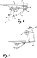
- the Figure 5 shows how a bottle 23 is held between the contact surfaces 10 and 11 in a holder 24.
- This holder could also be designed to hold a box, as a luggage carrier or to hold a rear light (not shown).
- Figures 6 and 7 show that instead of two contact surfaces arranged next to each other, several contact surfaces can be arranged one above the other, in particular as a square or rectangle.
- Figure 6 Contact surfaces 25, 26, 27 and 28, which are designed like the contact surfaces 10 and 11 and are square arrangement, but can be individually moved and positioned using mechanisms 29 and 30.
- the Figure 8 shows spherical contact surfaces 40 to 43, which are arranged in the base body 46 so as to be rotatable about axes 44 and 45.
- the Figure 10 shows a special embodiment of a backrest 60 with balls 64, 65 mounted in a ring 61, 62 around a substantially horizontal axis 63. These are held on two parallel struts 66, 67, which allow a limited rotation about a vertical axis and a limited pivoting about a horizontal axis.
- FIG 10 an embodiment of a passive deflection of the backrest 60 by means of the shape and the choice of material of the base body
- Figure 11 an embodiment of a backrest 70 for adjusting the angular position of the contact surface of the two balls 71 and 72 by deforming the base body 73 by means of a pressure cylinder 74.
- this pressure cylinder 74 is arranged between a lower lever arm 75 and an upper lever arm 76 in order to change the angle at which the lever arms 75 and 76 are arranged relative to one another.
- the pressure cylinder can act passively as a gas pressure spring or actively pneumatically or hydraulically according to a control (not shown).
- Pressure sensors (not shown) arranged in the balls 71, 72 can record a contact pressure that is applied by the user to the contact surfaces and transmit this pressure to a receiver via a transmitter (not shown).
- the Contact pressure can also be used to adjust or control the pressure on the pressure cylinder 74.
Landscapes
- Engineering & Computer Science (AREA)
- Mechanical Engineering (AREA)
- Chairs For Special Purposes, Such As Reclining Chairs (AREA)
Claims (14)
- Engin (2) entraîné par une pédale, pourvu d'une selle (4) dotée d'un soutien lombaire comprenant un support de montage (5) pour la fixation sur l'engin (2) et au moins deux surfaces d'appui (40 à 43) écartées, assurant l'appui d'une personne se servant de l'engin, le soutien lombaire comportant un corps de base (46, 51, 73) sur lequel est placée au moins une surface d'appui (40 à 43) en forme de segment sphérique, une en forme de segment de rouleau, placée à la parallèle de la pédale et / ou une placée en étant mobile par rapport au corps de base, au moins une surface d'appui (40 à 43) étant la surface d'une sphère (8, 9) ou d'un rouleau (47, 48) et au moins une surface d'appui (40 à 43) étant logée de manière élastique par rapport au corps de base, caractérisé en ce que la surface d'appui (40 à 43) est conçue en étant élastique et logée en étant mobile autour d'un axe (49, 50).
- Engin (2) entraîné par une pédale selon la revendication 1, caractérisé en ce que l'écart mutuel entre les surfaces d'appui (10, 11) est réglable en pouvant être fixé.
- Engin (2) entraîné par une pédale selon la revendication 1 ou 2, caractérisé en ce que les surfaces d'appui (10, 11) sont placées de part et d'autre du support de montage.
- Engin (2) entraîné par une pédale selon l'une quelconque des revendications précédentes, caractérisé en ce que plusieurs surfaces d'appui (10, 11) sont logées conjointement de manière élastique par rapport au corps de base (7).
- Engin (2) entraîné par une pédale selon l'une quelconque des revendications précédentes, caractérisé en ce que le corps de base (7) comporte au moins deux bras de levier (14, 15), qui par l'intermédiaire d'une articulation (16) sont assemblés de manière réglable l'un avec l'autre.
- Engin (2) entraîné par une pédale selon l'une quelconque des revendications précédentes, caractérisé en ce que le corps de base (7) comporte au moins deux bras de levier (14, 15) et en ce que la longueur d'au moins l'un des bras de levier est réglable.
- Engin (2) entraîné par une pédale selon l'une quelconque des revendications précédentes, caractérisé en ce que le corps de base (7) comporte un dispositif de fixation (17) sur la selle, destiné à être fixé sur une selle (4).
- Engin (2) entraîné par une pédale selon l'une quelconque des revendications précédentes, caractérisé en ce que le corps de base (7) comporte un dispositif de fixation (19) sur le tube de selle, destiné à être fixé sur un tube de selle (3).
- Engin (2) entraîné par une pédale selon la revendication 7 et 8, caractérisé en ce qu 'une entretoise d'assemblage est assemblée de manière articulée avec le dispositif de fixation (17) sur la selle et le dispositif de fixation (19) sur le tube de selle.
- Engin (2) entraîné par une pédale selon l'une quelconque des revendications précédentes, caractérisé en ce que le soutien lombaire comporte plusieurs surfaces d'appui (10, 11) et entre lesdites surfaces d'appui (10, 11) un support de montage (24).
- Engin (2) entraîné par une pédale selon l'une quelconque des revendications précédentes, caractérisé en ce que le soutien lombaire comporte une housse de selle et / ou un antivol pour bicyclette.
- Engin (2) entraîné par une pédale selon l'une quelconque des revendications précédentes, caractérisé en ce que le soutien lombaire comporte un éclairage de bicyclette.
- Engin (2) entraîné par une pédale selon l'une quelconque des revendications précédentes, caractérisé en ce que le soutien lombaire comporte un émetteur.
- Engin (2) entraîné par une pédale selon l'une quelconque des revendications précédentes, caractérisé en ce que le soutien lombaire comporte un capteur et un cylindre de pression (74), pour modifier la position de la surface d'appui (6), pour faire varier de ce fait la pression de contact de la surface d'appui (6) sur le dos d'un utilisateur.
Applications Claiming Priority (2)
| Application Number | Priority Date | Filing Date | Title |
|---|---|---|---|
| AT601212017 | 2017-11-04 | ||
| PCT/DE2018/000170 WO2019086059A1 (fr) | 2017-11-04 | 2018-06-05 | Soutien lombaire comprenant un moyen de fixation, selle pourvue d'un soutien lombaire et appareil pourvu de cette selle |
Publications (3)
| Publication Number | Publication Date |
|---|---|
| EP3573883A1 EP3573883A1 (fr) | 2019-12-04 |
| EP3573883C0 EP3573883C0 (fr) | 2024-08-07 |
| EP3573883B1 true EP3573883B1 (fr) | 2024-08-07 |
Family
ID=63144782
Family Applications (1)
| Application Number | Title | Priority Date | Filing Date |
|---|---|---|---|
| EP18752413.7A Active EP3573883B1 (fr) | 2017-11-04 | 2018-06-05 | Soutien lombaire comprenant un moyen de fixation, selle pourvue d'un soutien lombaire et appareil pourvu de cette selle |
Country Status (5)
| Country | Link |
|---|---|
| US (1) | US11453451B2 (fr) |
| EP (1) | EP3573883B1 (fr) |
| DE (1) | DE112018005190A5 (fr) |
| ES (1) | ES2996532T3 (fr) |
| WO (1) | WO2019086059A1 (fr) |
Families Citing this family (4)
| Publication number | Priority date | Publication date | Assignee | Title |
|---|---|---|---|---|
| DE102019007411A1 (de) * | 2019-10-24 | 2021-04-29 | Josef Bogenschütz | Rückenstütze |
| DE102020122627A1 (de) * | 2020-08-31 | 2022-03-03 | Bayerische Motoren Werke Aktiengesellschaft | Neigefahrzeug mit Trägervorrichtung |
| US11352089B1 (en) * | 2021-05-30 | 2022-06-07 | Cyclingdeal Usa, Inc. | Water bottle holder assembly for bicycles |
| CN216887018U (zh) * | 2022-03-03 | 2022-07-05 | 北京优贝百祺科技股份有限公司 | 一种带有水壶的鞍座 |
Citations (8)
| Publication number | Priority date | Publication date | Assignee | Title |
|---|---|---|---|---|
| BE403805A (fr) * | 1934-06-19 | 1934-07-31 | ||
| US4313639A (en) * | 1979-05-29 | 1982-02-02 | Ware Manufacturing, Incorporated | Motorcycle backrest |
| US5027795A (en) * | 1989-08-04 | 1991-07-02 | Kabushiki Kaisha Kato Haguruma Kogyosho | Massage machine for automobile |
| US5416936A (en) * | 1992-08-30 | 1995-05-23 | Chan; Hoi C. | Rolling-massaging mattress or cushion |
| US5887943A (en) * | 1996-05-20 | 1999-03-30 | Lee; Christopher J. | Bicycle seat thrust support |
| US20070249975A1 (en) * | 2006-04-19 | 2007-10-25 | Cheng-Kuei Pan | Portable ball-containing massage device |
| US20140336550A1 (en) * | 2012-06-18 | 2014-11-13 | James E. Zedaker | Rolling Ball Massager |
| CN205359905U (zh) * | 2016-02-01 | 2016-07-06 | 安徽理工大学 | 电动车车载式背部按摩装置 |
Family Cites Families (15)
| Publication number | Priority date | Publication date | Assignee | Title |
|---|---|---|---|---|
| US1113833A (en) * | 1914-05-13 | 1914-10-13 | Christian S Ruff | Adjustable and collapsible autocycle seat-back. |
| US4466660A (en) * | 1982-02-22 | 1984-08-21 | Earl Mabie | Movable backrest for tandem seat motorcycles |
| CN2622050Y (zh) * | 2003-05-14 | 2004-06-30 | 刘振生 | 保健车座 |
| JP2011011607A (ja) * | 2009-07-01 | 2011-01-20 | Alps Electric Co Ltd | 自転車 |
| KR101040331B1 (ko) * | 2011-03-03 | 2011-06-14 | 한준희 | 등받이 겸용 자전거 잠금 장치 |
| CN103879481A (zh) * | 2012-12-19 | 2014-06-25 | 于曾 | 一种自行车按摩靠背 |
| CN203306183U (zh) * | 2013-06-07 | 2013-11-27 | 刘海坤 | 一种健身增力自行车 |
| US10478372B1 (en) * | 2013-12-24 | 2019-11-19 | Albert John Rock | Motorcycle seat massage system |
| CN204309934U (zh) * | 2014-10-30 | 2015-05-06 | 天津佰金科技有限公司 | 折叠车座 |
| US9592874B2 (en) | 2014-12-19 | 2017-03-14 | Meizhou XiuYing Enterprise Company Limited | Intelligent bicycle |
| AT516985B1 (de) | 2015-02-02 | 2018-04-15 | Knabl Josef | Absperrvorrichtung für Fahrräder |
| TWI537163B (zh) * | 2015-07-30 | 2016-06-11 | 昇詠鎖業有限公司 | 多用途自行車鎖結構 |
| CN106608330A (zh) * | 2015-10-22 | 2017-05-03 | 天津赛克电动车有限公司 | 一种电动自行车的车座靠背装置 |
| US10368647B2 (en) * | 2015-11-16 | 2019-08-06 | Kirk Edward Schenck | Backrest for a seating device |
| CN205524626U (zh) * | 2016-01-25 | 2016-08-31 | 潘行亦 | 自行车车座帽 |
-
2018
- 2018-06-05 WO PCT/DE2018/000170 patent/WO2019086059A1/fr not_active Ceased
- 2018-06-05 EP EP18752413.7A patent/EP3573883B1/fr active Active
- 2018-06-05 ES ES18752413T patent/ES2996532T3/es active Active
- 2018-06-05 US US16/760,604 patent/US11453451B2/en active Active
- 2018-06-05 DE DE112018005190.0T patent/DE112018005190A5/de not_active Withdrawn
Patent Citations (8)
| Publication number | Priority date | Publication date | Assignee | Title |
|---|---|---|---|---|
| BE403805A (fr) * | 1934-06-19 | 1934-07-31 | ||
| US4313639A (en) * | 1979-05-29 | 1982-02-02 | Ware Manufacturing, Incorporated | Motorcycle backrest |
| US5027795A (en) * | 1989-08-04 | 1991-07-02 | Kabushiki Kaisha Kato Haguruma Kogyosho | Massage machine for automobile |
| US5416936A (en) * | 1992-08-30 | 1995-05-23 | Chan; Hoi C. | Rolling-massaging mattress or cushion |
| US5887943A (en) * | 1996-05-20 | 1999-03-30 | Lee; Christopher J. | Bicycle seat thrust support |
| US20070249975A1 (en) * | 2006-04-19 | 2007-10-25 | Cheng-Kuei Pan | Portable ball-containing massage device |
| US20140336550A1 (en) * | 2012-06-18 | 2014-11-13 | James E. Zedaker | Rolling Ball Massager |
| CN205359905U (zh) * | 2016-02-01 | 2016-07-06 | 安徽理工大学 | 电动车车载式背部按摩装置 |
Also Published As
| Publication number | Publication date |
|---|---|
| EP3573883A1 (fr) | 2019-12-04 |
| EP3573883C0 (fr) | 2024-08-07 |
| US20200255081A1 (en) | 2020-08-13 |
| DE112018005190A5 (de) | 2020-06-18 |
| US11453451B2 (en) | 2022-09-27 |
| WO2019086059A1 (fr) | 2019-05-09 |
| ES2996532T3 (en) | 2025-02-12 |
Similar Documents
| Publication | Publication Date | Title |
|---|---|---|
| EP3573883B1 (fr) | Soutien lombaire comprenant un moyen de fixation, selle pourvue d'un soutien lombaire et appareil pourvu de cette selle | |
| EP1878608A2 (fr) | Siège de véhicule automobile | |
| DE19602909A1 (de) | Kopfstütze für Fahrzeugsitze | |
| EP3972891B1 (fr) | Appui dorsal pour engins à pédales | |
| DE69506140T2 (de) | Fahrradrahmen mit einstellbarer Geometrie | |
| EP3208183B1 (fr) | Dispositif de palier de selle | |
| DE9320441U1 (de) | Massagestuhl mit einer einstellbaren Rückenlehnenstütze | |
| DE2612263A1 (de) | Sitzanordnung fuer fahrzeuge, insbesondere kraftfahrzeuge | |
| EP3815653B1 (fr) | Appui-tête | |
| DE202015100223U1 (de) | Möbel | |
| DE102014006058A1 (de) | Bürostuhl mit Synchronmechanik | |
| DE102019131595B4 (de) | Fahrzeugsitz | |
| DE20002185U1 (de) | Sattelträger | |
| EP0569570B1 (fr) | Dispositif pour assurer la suspension et le reglage de la force portante d'une selle de vehicule | |
| DE202017004421U1 (de) | Sattellagervorrichtung | |
| AT296055B (de) | Gestell für Fahrzeugsitze od.dgl. | |
| DE4416196C2 (de) | Federungsanordnung für den Sattel von Motor- oder Fahrrädern | |
| AT392578B (de) | Lehnsessel | |
| EP3369648A1 (fr) | Système pour une draisienne ou pour une bicyclette ainsi qu'une draisienne ou une bicyclette correspondantes | |
| DE202018006315U1 (de) | Fahrradsattel | |
| DE20215136U1 (de) | Fahrradsattel | |
| WO2000043073A1 (fr) | Exerciseur et chaise equipee d'un tel exerciseur | |
| DE602006000025T2 (de) | Fahrzeug-Kindersitz | |
| DE29514455U1 (de) | Lenkvorrichtung mit Abfederungen für Zwei-Dreiräder, insbesondere für Fahrräder, wodurch auftretende Stöße von Unebenheiten der Fahrbeläge abgefangen werden | |
| DE10131862A1 (de) | Kopfstütze für einen Sitz und Sitz mit Lehne und Kopfstütze |
Legal Events
| Date | Code | Title | Description |
|---|---|---|---|
| STAA | Information on the status of an ep patent application or granted ep patent |
Free format text: STATUS: UNKNOWN |
|
| STAA | Information on the status of an ep patent application or granted ep patent |
Free format text: STATUS: THE INTERNATIONAL PUBLICATION HAS BEEN MADE |
|
| PUAI | Public reference made under article 153(3) epc to a published international application that has entered the european phase |
Free format text: ORIGINAL CODE: 0009012 |
|
| STAA | Information on the status of an ep patent application or granted ep patent |
Free format text: STATUS: REQUEST FOR EXAMINATION WAS MADE |
|
| 17P | Request for examination filed |
Effective date: 20190830 |
|
| AK | Designated contracting states |
Kind code of ref document: A1 Designated state(s): AL AT BE BG CH CY CZ DE DK EE ES FI FR GB GR HR HU IE IS IT LI LT LU LV MC MK MT NL NO PL PT RO RS SE SI SK SM TR |
|
| AX | Request for extension of the european patent |
Extension state: BA ME |
|
| STAA | Information on the status of an ep patent application or granted ep patent |
Free format text: STATUS: EXAMINATION IS IN PROGRESS |
|
| 17Q | First examination report despatched |
Effective date: 20201211 |
|
| DAV | Request for validation of the european patent (deleted) | ||
| DAX | Request for extension of the european patent (deleted) | ||
| GRAP | Despatch of communication of intention to grant a patent |
Free format text: ORIGINAL CODE: EPIDOSNIGR1 |
|
| STAA | Information on the status of an ep patent application or granted ep patent |
Free format text: STATUS: GRANT OF PATENT IS INTENDED |
|
| GRAJ | Information related to disapproval of communication of intention to grant by the applicant or resumption of examination proceedings by the epo deleted |
Free format text: ORIGINAL CODE: EPIDOSDIGR1 |
|
| STAA | Information on the status of an ep patent application or granted ep patent |
Free format text: STATUS: EXAMINATION IS IN PROGRESS |
|
| INTG | Intention to grant announced |
Effective date: 20221130 |
|
| INTC | Intention to grant announced (deleted) | ||
| RAP1 | Party data changed (applicant data changed or rights of an application transferred) |
Owner name: B&T INNOTEC GERMANY GMBH |
|
| RIN1 | Information on inventor provided before grant (corrected) |
Inventor name: TSCHEINIG, ANDREAS Inventor name: BOGENSCHUETZ, JOSEF |
|
| GRAP | Despatch of communication of intention to grant a patent |
Free format text: ORIGINAL CODE: EPIDOSNIGR1 |
|
| STAA | Information on the status of an ep patent application or granted ep patent |
Free format text: STATUS: GRANT OF PATENT IS INTENDED |
|
| GRAS | Grant fee paid |
Free format text: ORIGINAL CODE: EPIDOSNIGR3 |
|
| INTG | Intention to grant announced |
Effective date: 20240220 |
|
| GRAA | (expected) grant |
Free format text: ORIGINAL CODE: 0009210 |
|
| STAA | Information on the status of an ep patent application or granted ep patent |
Free format text: STATUS: THE PATENT HAS BEEN GRANTED |
|
| P01 | Opt-out of the competence of the unified patent court (upc) registered |
Free format text: CASE NUMBER: APP_36454/2024 Effective date: 20240618 |
|
| AK | Designated contracting states |
Kind code of ref document: B1 Designated state(s): AL AT BE BG CH CY CZ DE DK EE ES FI FR GB GR HR HU IE IS IT LI LT LU LV MC MK MT NL NO PL PT RO RS SE SI SK SM TR |
|
| REG | Reference to a national code |
Ref country code: GB Ref legal event code: FG4D Free format text: NOT ENGLISH |
|
| REG | Reference to a national code |
Ref country code: CH Ref legal event code: EP |
|
| REG | Reference to a national code |
Ref country code: IE Ref legal event code: FG4D Free format text: LANGUAGE OF EP DOCUMENT: GERMAN |
|
| REG | Reference to a national code |
Ref country code: DE Ref legal event code: R096 Ref document number: 502018014988 Country of ref document: DE |
|
| U01 | Request for unitary effect filed |
Effective date: 20240904 |
|
| U07 | Unitary effect registered |
Designated state(s): AT BE BG DE DK EE FI FR IT LT LU LV MT NL PT RO SE SI Effective date: 20240917 |
|
| P04 | Withdrawal of opt-out of the competence of the unified patent court (upc) registered |
Free format text: CASE NUMBER: APP_51632/2024 Effective date: 20240913 |
|
| P05 | Withdrawal of opt-out of the competence of the unified patent court (upc) changed |
Free format text: CASE NUMBER: APP_51632/2024 Effective date: 20240917 |
|
| PG25 | Lapsed in a contracting state [announced via postgrant information from national office to epo] |
Ref country code: NO Free format text: LAPSE BECAUSE OF FAILURE TO SUBMIT A TRANSLATION OF THE DESCRIPTION OR TO PAY THE FEE WITHIN THE PRESCRIBED TIME-LIMIT Effective date: 20241107 |
|
| PG25 | Lapsed in a contracting state [announced via postgrant information from national office to epo] |
Ref country code: PL Free format text: LAPSE BECAUSE OF FAILURE TO SUBMIT A TRANSLATION OF THE DESCRIPTION OR TO PAY THE FEE WITHIN THE PRESCRIBED TIME-LIMIT Effective date: 20240807 Ref country code: GR Free format text: LAPSE BECAUSE OF FAILURE TO SUBMIT A TRANSLATION OF THE DESCRIPTION OR TO PAY THE FEE WITHIN THE PRESCRIBED TIME-LIMIT Effective date: 20241108 |
|
| PG25 | Lapsed in a contracting state [announced via postgrant information from national office to epo] |
Ref country code: IS Free format text: LAPSE BECAUSE OF FAILURE TO SUBMIT A TRANSLATION OF THE DESCRIPTION OR TO PAY THE FEE WITHIN THE PRESCRIBED TIME-LIMIT Effective date: 20241207 |
|
| PG25 | Lapsed in a contracting state [announced via postgrant information from national office to epo] |
Ref country code: HR Free format text: LAPSE BECAUSE OF FAILURE TO SUBMIT A TRANSLATION OF THE DESCRIPTION OR TO PAY THE FEE WITHIN THE PRESCRIBED TIME-LIMIT Effective date: 20240807 |
|
| PG25 | Lapsed in a contracting state [announced via postgrant information from national office to epo] |
Ref country code: RS Free format text: LAPSE BECAUSE OF FAILURE TO SUBMIT A TRANSLATION OF THE DESCRIPTION OR TO PAY THE FEE WITHIN THE PRESCRIBED TIME-LIMIT Effective date: 20241107 |
|
| PG25 | Lapsed in a contracting state [announced via postgrant information from national office to epo] |
Ref country code: RS Free format text: LAPSE BECAUSE OF FAILURE TO SUBMIT A TRANSLATION OF THE DESCRIPTION OR TO PAY THE FEE WITHIN THE PRESCRIBED TIME-LIMIT Effective date: 20241107 Ref country code: PL Free format text: LAPSE BECAUSE OF FAILURE TO SUBMIT A TRANSLATION OF THE DESCRIPTION OR TO PAY THE FEE WITHIN THE PRESCRIBED TIME-LIMIT Effective date: 20240807 Ref country code: NO Free format text: LAPSE BECAUSE OF FAILURE TO SUBMIT A TRANSLATION OF THE DESCRIPTION OR TO PAY THE FEE WITHIN THE PRESCRIBED TIME-LIMIT Effective date: 20241107 Ref country code: IS Free format text: LAPSE BECAUSE OF FAILURE TO SUBMIT A TRANSLATION OF THE DESCRIPTION OR TO PAY THE FEE WITHIN THE PRESCRIBED TIME-LIMIT Effective date: 20241207 Ref country code: HR Free format text: LAPSE BECAUSE OF FAILURE TO SUBMIT A TRANSLATION OF THE DESCRIPTION OR TO PAY THE FEE WITHIN THE PRESCRIBED TIME-LIMIT Effective date: 20240807 Ref country code: GR Free format text: LAPSE BECAUSE OF FAILURE TO SUBMIT A TRANSLATION OF THE DESCRIPTION OR TO PAY THE FEE WITHIN THE PRESCRIBED TIME-LIMIT Effective date: 20241108 |
|
| REG | Reference to a national code |
Ref country code: ES Ref legal event code: FG2A Ref document number: 2996532 Country of ref document: ES Kind code of ref document: T3 Effective date: 20250212 |
|
| PG25 | Lapsed in a contracting state [announced via postgrant information from national office to epo] |
Ref country code: SM Free format text: LAPSE BECAUSE OF FAILURE TO SUBMIT A TRANSLATION OF THE DESCRIPTION OR TO PAY THE FEE WITHIN THE PRESCRIBED TIME-LIMIT Effective date: 20240807 |
|
| PG25 | Lapsed in a contracting state [announced via postgrant information from national office to epo] |
Ref country code: CZ Free format text: LAPSE BECAUSE OF FAILURE TO SUBMIT A TRANSLATION OF THE DESCRIPTION OR TO PAY THE FEE WITHIN THE PRESCRIBED TIME-LIMIT Effective date: 20240807 |
|
| PG25 | Lapsed in a contracting state [announced via postgrant information from national office to epo] |
Ref country code: SK Free format text: LAPSE BECAUSE OF FAILURE TO SUBMIT A TRANSLATION OF THE DESCRIPTION OR TO PAY THE FEE WITHIN THE PRESCRIBED TIME-LIMIT Effective date: 20240807 |
|
| PLBE | No opposition filed within time limit |
Free format text: ORIGINAL CODE: 0009261 |
|
| STAA | Information on the status of an ep patent application or granted ep patent |
Free format text: STATUS: NO OPPOSITION FILED WITHIN TIME LIMIT |
|
| PGFP | Annual fee paid to national office [announced via postgrant information from national office to epo] |
Ref country code: GB Payment date: 20250618 Year of fee payment: 8 |
|
| 26N | No opposition filed |
Effective date: 20250508 |
|
| U20 | Renewal fee for the european patent with unitary effect paid |
Year of fee payment: 8 Effective date: 20250624 |
|
| PGFP | Annual fee paid to national office [announced via postgrant information from national office to epo] |
Ref country code: ES Payment date: 20250728 Year of fee payment: 8 |
|
| PGFP | Annual fee paid to national office [announced via postgrant information from national office to epo] |
Ref country code: CH Payment date: 20250701 Year of fee payment: 8 |
|
| PG25 | Lapsed in a contracting state [announced via postgrant information from national office to epo] |
Ref country code: MC Free format text: LAPSE BECAUSE OF FAILURE TO SUBMIT A TRANSLATION OF THE DESCRIPTION OR TO PAY THE FEE WITHIN THE PRESCRIBED TIME-LIMIT Effective date: 20240807 |
|
| PG25 | Lapsed in a contracting state [announced via postgrant information from national office to epo] |
Ref country code: IE Free format text: LAPSE BECAUSE OF NON-PAYMENT OF DUE FEES Effective date: 20250605 |