EP3574247B1 - Raccord hydraulique mâle à face plate - Google Patents
Raccord hydraulique mâle à face plate Download PDFInfo
- Publication number
- EP3574247B1 EP3574247B1 EP18703926.8A EP18703926A EP3574247B1 EP 3574247 B1 EP3574247 B1 EP 3574247B1 EP 18703926 A EP18703926 A EP 18703926A EP 3574247 B1 EP3574247 B1 EP 3574247B1
- Authority
- EP
- European Patent Office
- Prior art keywords
- valve portion
- flat face
- sealing means
- sealing
- hydraulic coupling
- Prior art date
- Legal status (The legal status is an assumption and is not a legal conclusion. Google has not performed a legal analysis and makes no representation as to the accuracy of the status listed.)
- Active
Links
Images

Classifications
-
- F—MECHANICAL ENGINEERING; LIGHTING; HEATING; WEAPONS; BLASTING
- F16—ENGINEERING ELEMENTS AND UNITS; GENERAL MEASURES FOR PRODUCING AND MAINTAINING EFFECTIVE FUNCTIONING OF MACHINES OR INSTALLATIONS; THERMAL INSULATION IN GENERAL
- F16L—PIPES; JOINTS OR FITTINGS FOR PIPES; SUPPORTS FOR PIPES, CABLES OR PROTECTIVE TUBING; MEANS FOR THERMAL INSULATION IN GENERAL
- F16L37/00—Couplings of the quick-acting type
- F16L37/28—Couplings of the quick-acting type with fluid cut-off means
- F16L37/30—Couplings of the quick-acting type with fluid cut-off means with fluid cut-off means in each of two pipe-end fittings
- F16L37/32—Couplings of the quick-acting type with fluid cut-off means with fluid cut-off means in each of two pipe-end fittings at least one of two lift valves being opened automatically when the coupling is applied
- F16L37/34—Couplings of the quick-acting type with fluid cut-off means with fluid cut-off means in each of two pipe-end fittings at least one of two lift valves being opened automatically when the coupling is applied at least one of the lift valves being of the sleeve type, i.e. a sleeve being telescoped over an inner cylindrical wall
-
- F—MECHANICAL ENGINEERING; LIGHTING; HEATING; WEAPONS; BLASTING
- F16—ENGINEERING ELEMENTS AND UNITS; GENERAL MEASURES FOR PRODUCING AND MAINTAINING EFFECTIVE FUNCTIONING OF MACHINES OR INSTALLATIONS; THERMAL INSULATION IN GENERAL
- F16L—PIPES; JOINTS OR FITTINGS FOR PIPES; SUPPORTS FOR PIPES, CABLES OR PROTECTIVE TUBING; MEANS FOR THERMAL INSULATION IN GENERAL
- F16L37/00—Couplings of the quick-acting type
- F16L37/22—Couplings of the quick-acting type in which the connection is maintained by means of balls, rollers or helical springs under radial pressure between the parts
- F16L37/23—Couplings of the quick-acting type in which the connection is maintained by means of balls, rollers or helical springs under radial pressure between the parts by means of balls
-
- F—MECHANICAL ENGINEERING; LIGHTING; HEATING; WEAPONS; BLASTING
- F16—ENGINEERING ELEMENTS AND UNITS; GENERAL MEASURES FOR PRODUCING AND MAINTAINING EFFECTIVE FUNCTIONING OF MACHINES OR INSTALLATIONS; THERMAL INSULATION IN GENERAL
- F16L—PIPES; JOINTS OR FITTINGS FOR PIPES; SUPPORTS FOR PIPES, CABLES OR PROTECTIVE TUBING; MEANS FOR THERMAL INSULATION IN GENERAL
- F16L37/00—Couplings of the quick-acting type
- F16L37/28—Couplings of the quick-acting type with fluid cut-off means
- F16L37/30—Couplings of the quick-acting type with fluid cut-off means with fluid cut-off means in each of two pipe-end fittings
- F16L37/32—Couplings of the quick-acting type with fluid cut-off means with fluid cut-off means in each of two pipe-end fittings at least one of two lift valves being opened automatically when the coupling is applied
- F16L37/35—Couplings of the quick-acting type with fluid cut-off means with fluid cut-off means in each of two pipe-end fittings at least one of two lift valves being opened automatically when the coupling is applied at least one of the valves having an axial bore communicating with lateral apertures
Definitions
- the invention relates to a flat face male hydraulic coupling which may be used to connect hoses under pressure, comprising:
- Flat face hydraulic couplings are typically used to connect pressurized hydraulic fluid lines. Due to the construction of a connect under pressure flat face hydraulic coupling, it is not necessary to depressurize the hydraulic system.
- a flat face hydraulic coupling suitable to connect under pressure typically consists of a female and a male coupling, wherein the male coupling is arranged to the pressurized fluid line.
- the female coupling will provide a mechanical coupling to the male coupling.
- EP2626612A1 describes a coupling device with residual pressure relief system.
- DE 202006003300 discloses a hydraulic coupling, wherein a telescopic valve body assembly is provided.
- the inner space is in contact with ambient air and accordingly no fluid needs to be compressed for the telescopic valve body assembly to be moved.
- the pressure is not relieved over the second sealing means.
- the pusher rod of the female coupling operates a small hydraulic actuator arranged in the male connector, which generates sufficient force to directly move a third valve portion and to overcome the pressure difference over the second sealing means.
- This object of the invention is achieved with a flat face male hydraulic coupling according to the preamble, which coupling is characterized in that the first valve portion is provided with a recess on an outer surface, which recess is positioned outside of the third sealing means in the first position and which recess overlaps with one stage of the two stage sealing in the second position, such that pressure is relieved over the second sealing means via the relief passage and the recess.
- first valve portion With the recess arranged in the outer surface of first valve portion it is possible to provide a pressure relieve path, which remains outside of the inner space of the valve body assembly. As a result, the inner space can remain separated from the hydraulic fluid and the force required to move the first valve portion from the first to the second position is reduced as no hydraulic fluid needs to be diverted as is the case with the prior art.
- the second sealing means seal a transition surface from the first diameter to the second diameter.
- the continuous passage widens allowing for an easy sealing in axial direction of the second valve portion in the second position to the surface of the continuous passage.
- the sealing will be lifted allowing for a free flow of hydraulic fluid.
- the first sealing means and second sealing means each comprise at least one O-ring.
- each stage of the third sealing means comprises an O-ring arranged in circumferential grooves in an inner surface of the second valve portion.
- a flow path is formed between the surface of the continuous passage, the outer surface of the first valve portion and the outer surface of the second valve portion.
- an inner space of the valve body assembly is sealed with respect to an outside of the valve body assembly.
- the inner space is exclusively filled with a compressible gas, such as air.
- the inner space of the telescopic valve body assembly By having the inner space of the telescopic valve body assembly being sealed with respect to the outside of the valve body assembly, it is prevented that any hydraulic fluid flowing along the valve body assembly penetrates the inner space. As no hydraulic fluid can enter the inner space, only the medium, which is preferably a compressible gas, such as air, needs to be compressed when the flat face male hydraulic coupling is inserted into the flat face female hydraulic coupling. This results in a reduction of the insertion force, while having a male coupling with few parts.
- a compressible gas such as air
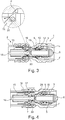
- Figures 1 - 4 show in cross-section an embodiment of a flat face male hydraulic coupling suitable to connect under pressure in different stages of coupling with a flat face female hydraulic coupling.
- Figure 1 shows a flat face male hydraulic coupling 1 and a flat face female hydraulic coupling 2 which are suitable to connect under pressure.
- the male coupling 1 has a body 3 with a continuous passage 4 having a first section with diameter d 1 and a second section with diameter d 2 .
- a valve body assembly having a first valve portion 5 and a second valve portion 6 telescopic arranged on the first valve portion 5, is arranged in the continuous passage 4.
- a first O-ring 7 is provided to seal the first valve portion 5 to the surface of the continuous passage 4.
- a second O-ring 8 is provided to seal the second valve portion 6 to transition surface 9, where the continuous passage 4 widens from the first diameter d 1 to the second diameter d 2 .
- a two stage sealing 10, 11 is provided in the inner surface of the second valve portion 6 to seal the first valve portion 5.
- a relieve passage 12 is arranged between the first stage O-ring 10 and the second stage O-ring 11.
- the flat face female hydraulic coupling 2 is not fully described, but has at least a body 13 with a pusher rod 14 and a fluid channel 15 for passage of hydraulic fluid. Furthermore a locking sleeve 16 co-acting with balls 17 is provided on the outside of the body 13.
- FIG 2 the male 1 and female 2 couplings are shown partially inserted.
- the pusher rod 14 has pushed the first valve portion 5 from a first position into the second valve portion 6.
- Figure 3 shows both couplings 1, 2 inserted further, wherein the first valve portion has reached the second position.
- a recess 18 arranged on the outer surface of the first valve portion 5 is moved under the first stage O-ring 10 such that hydraulic fluid F can flow from continuous passage 4 via the relieve passage 12 through the recess 18 into the space 19 between the surface of the continuous passage and the first valve portion 5.
- the first O-ring seals onto the fluid channel 15 and the seal 20 is released from the inside of the fluid channel 15, the pressure around the second seal 8 is relieved and a small fluid flow F is possible through the passage 12 into the space 19 along the released seal 20 into the female coupling.
- Figure 4 shows both couplings 1, 2 in full connected position.
- the pusher rod 14 has pushed the first valve portion 5 to a third position taking the second valve portion 6 along, such that a passage 21 past the second seal 8 is opened.
- the body 3 Due to this final movement, the body 3 has pushed the fluid channel 15 off the pusher rod 14, such that a passage 22 is created and a free fluid flow of hydraulic fluid F is allowed through the male coupling 1 to the female coupling 2.
- the balls 17 of the locking sleeve 16 are accommodated in an outer circumferential groove on the body 3, such that the locking sleeve 16 will be shifted and the coupling of male coupling 1 and female coupling 2 is locked.
Landscapes
- Engineering & Computer Science (AREA)
- General Engineering & Computer Science (AREA)
- Mechanical Engineering (AREA)
- Quick-Acting Or Multi-Walled Pipe Joints (AREA)
Claims (7)
- Couplage hydraulique mâle à face plate (1) comprenant :- un corps (3) avec un passage continu (4) ayant une première section avec un premier diamètre (d1) et un second diamètre de section (d2), dans lequel le premier diamètre (d1) est plus petit que le second diamètre (d2) ;- un ensemble corps de soupape (5, 6) agencé de manière mobile dans le passage continu (4), lequel ensemble corps de soupape comprend une première portion de soupape (5) et une seconde portion de soupape (6) agencée de manière télescopique autour de la première portion de soupape (5), dans lequel la première portion de soupape (5) peut être déplacée entre des première, deuxième et troisième positions et dans lequel la seconde portion de soupape (6) est emportée par la première portion de soupape (5) entre les deuxième et troisième positions ;- un premier moyen d'étanchéité (7) pour assurer l'étanchéité de la première portion de soupape (5) dans la première position par rapport à une surface du passage continu (4) ;- un deuxième moyen d'étanchéité (8) pour assurer l'étanchéité de la seconde portion de soupape (6) dans la deuxième position par rapport à la surface du passage continu (4) ; et- un troisième moyen d'étanchéité (10, 11) pour assurer l'étanchéité de la première portion de soupape (5) par rapport à la seconde portion de soupape (6), dans lequelle troisième moyen d'étanchéité est au moins une étanchéité à deux niveaux (10, 11) et dans lequel un passage de surpression (12) est agencé dans la seconde portion de soupape (6) s'étendant en direction radiale et entre les deux niveaux de l'étanchéité à deux niveaux (10, 11) ;
caractérisé en ce que
la première portion de soupape (5) est dotée d'un évidement (18) dans une surface externe, lequel l'évidement (18) est positionné à l'extérieur du troisième moyen d'étanchéité dans la première position et lequel l'évidement (18) chevauche un niveau de l'étanchéité à deux niveaux (10, 11) dans la deuxième position, de sorte qu'une pression soit relâchée, agissant sur le deuxième moyen d'étanchéité (8), par l'intermédiaire du passage de surpression (12) et de l'évidement (18). - Couplage hydraulique mâle à face plate (1) selon la revendication 1, dans lequel le deuxième moyen d'étanchéité assure l'étanchéité d'une surface de transition du premier diamètre (d1) au second diamètre (d2).
- Couplage hydraulique mâle à face plate (1) selon la revendication 1 ou 2, dans lequel le premier moyen d'étanchéité (7) et le deuxième moyen d'étanchéité (8) comprennent chacun au moins un joint torique.
- Couplage hydraulique mâle à face plate (1) selon l'une quelconque des revendications précédentes, dans lequel chaque niveau du troisième moyen d'étanchéité (10, 11) comprend un joint torique agencé dans des rainures circonférentielles dans une surface interne de la seconde portion de soupape (6).
- Couplage hydraulique mâle à face plate (1) selon l'une quelconque des revendications précédentes, dans lequel dans la troisième position de la première portion de soupape (5) un trajet d'écoulement est formé entre la surface du passage continu (4), la surface externe de la première portion de soupape (5) et une surface externe de la seconde portion de soupape (6).
- Couplage hydraulique mâle à face plate (1) selon l'une quelconque des revendications précédentes, dans lequel un espace interne de l'ensemble corps de soupape (5, 6) est étanche par rapport à un extérieur de l'ensemble corps de soupape.
- Couplage hydraulique mâle à face plate (1) selon la revendication 6, dans lequel l'espace interne est exclusivement rempli d'un gaz compressible, tel que l'air.
Applications Claiming Priority (2)
| Application Number | Priority Date | Filing Date | Title |
|---|---|---|---|
| IN201711003100 | 2017-01-27 | ||
| PCT/EP2018/051998 WO2018138284A1 (fr) | 2017-01-27 | 2018-01-26 | Raccord hydraulique mâle à face plate |
Publications (2)
| Publication Number | Publication Date |
|---|---|
| EP3574247A1 EP3574247A1 (fr) | 2019-12-04 |
| EP3574247B1 true EP3574247B1 (fr) | 2021-01-06 |
Family
ID=58688494
Family Applications (1)
| Application Number | Title | Priority Date | Filing Date |
|---|---|---|---|
| EP18703926.8A Active EP3574247B1 (fr) | 2017-01-27 | 2018-01-26 | Raccord hydraulique mâle à face plate |
Country Status (5)
| Country | Link |
|---|---|
| US (1) | US10612708B2 (fr) |
| EP (1) | EP3574247B1 (fr) |
| CA (1) | CA3051306C (fr) |
| GB (1) | GB2559208A (fr) |
| WO (1) | WO2018138284A1 (fr) |
Families Citing this family (7)
| Publication number | Priority date | Publication date | Assignee | Title |
|---|---|---|---|---|
| FR3044070B1 (fr) | 2015-11-20 | 2019-06-28 | A Raymond Et Cie | Raccord tubulaire securise a connexion automatique |
| WO2020057879A1 (fr) * | 2018-09-21 | 2020-03-26 | Eaton Intelligent Power Limited | Raccord hydraulique femelle, raccord hydraulique mâle et combinaison de ceux-ci |
| CN111120754A (zh) * | 2020-03-02 | 2020-05-08 | 江西艾克实业有限公司 | 一种新型可带压插拔的阀芯结构 |
| US11262014B2 (en) | 2020-06-10 | 2022-03-01 | Blue Origin, Llc | Quick disconnect coupling systems and related methods |
| CN215721555U (zh) * | 2021-02-07 | 2022-02-01 | 深圳市英维克智能连接技术有限公司 | 流体连接器及密封结构 |
| US12104729B2 (en) | 2022-08-30 | 2024-10-01 | A. Raymond Et Cie | Quick connector verification system and related method of use |
| CN115854138B (zh) * | 2022-12-19 | 2026-01-09 | 珠海格力智能装备有限公司 | 管路连接结构及家用电器 |
Family Cites Families (9)
| Publication number | Priority date | Publication date | Assignee | Title |
|---|---|---|---|---|
| US2727761A (en) * | 1951-10-27 | 1955-12-20 | Hughes Tool Co | Couplers for fluid-conducting conduits |
| SE468403B (sv) | 1990-01-17 | 1993-01-11 | Dart Engineering Ag | Anordning vid kopplingsdel som innefattar tryckreduceringsorgan |
| SE506226C2 (sv) * | 1996-03-05 | 1997-11-24 | Fritiof Hulden | Snabbkoppling med utifrån påverkbara tryckutjämningsdon |
| DE19624365C1 (de) * | 1996-06-19 | 1997-10-23 | Voswinkel Gmbh | Kupplungsteil einer Druckmittel-Steckkupplung |
| JP3711479B2 (ja) * | 1996-07-25 | 2005-11-02 | ニッタ・ムアー株式会社 | 管継手 |
| DE202006003300U1 (de) | 2006-03-02 | 2007-07-05 | Voswinkel Kg | Kupplungsteil einer Hydraulik-Steckkupplung |
| EP2626612B1 (fr) | 2012-02-08 | 2014-12-10 | Eaton SAS | Dispositif de couplage avec système de libération de pression résiduelle |
| CN104567521B (zh) * | 2014-12-16 | 2017-09-22 | 中航光电科技股份有限公司 | 散热器 |
| CN104500892A (zh) * | 2014-12-16 | 2015-04-08 | 中航光电科技股份有限公司 | 一种快速接头母头 |
-
2017
- 2017-03-16 GB GB1704212.8A patent/GB2559208A/en not_active Withdrawn
-
2018
- 2018-01-26 WO PCT/EP2018/051998 patent/WO2018138284A1/fr not_active Ceased
- 2018-01-26 EP EP18703926.8A patent/EP3574247B1/fr active Active
- 2018-01-26 CA CA3051306A patent/CA3051306C/fr active Active
- 2018-01-26 US US16/480,709 patent/US10612708B2/en active Active
Non-Patent Citations (1)
| Title |
|---|
| None * |
Also Published As
| Publication number | Publication date |
|---|---|
| GB201704212D0 (en) | 2017-05-03 |
| CA3051306A1 (fr) | 2018-08-02 |
| WO2018138284A1 (fr) | 2018-08-02 |
| US20190390809A1 (en) | 2019-12-26 |
| CA3051306C (fr) | 2020-10-27 |
| EP3574247A1 (fr) | 2019-12-04 |
| GB2559208A (en) | 2018-08-01 |
| US10612708B2 (en) | 2020-04-07 |
Similar Documents
| Publication | Publication Date | Title |
|---|---|---|
| CA3051306C (fr) | Raccord hydraulique male a face plate | |
| US5873386A (en) | Quick-release coupling | |
| CA2034307C (fr) | Ensemble d'elements de raccordement muni de detendeurs | |
| EP2431647B1 (fr) | Montage hydraulique pour tuyaux | |
| US10107059B2 (en) | Stab connector and method of use thereof | |
| US20140261818A1 (en) | Quick connect coupling | |
| EP3574248B2 (fr) | Accouplement hydraulique femelle à face plate | |
| KR20030066352A (ko) | 2개의 파이프의 탈착 가능한 접속을 위한 신속 연결부 | |
| CN103453207A (zh) | 排放和清除设备、包括这样的设备的连接端件以及连接器 | |
| US4676269A (en) | Connector assembly | |
| US11054075B2 (en) | Coupling element for a hydraulic coupling | |
| JP4454662B2 (ja) | 同軸継ぎ手 | |
| CA2390370C (fr) | Raccord rapide de conception plate | |
| EP2626612B1 (fr) | Dispositif de couplage avec système de libération de pression résiduelle | |
| EP0890053B1 (fr) | Couplage rapide pour tuyaux et canalisations destines a des milieux sous pression | |
| US6202690B1 (en) | Pressure balanced undersea hydraulic coupling | |
| JPH0152639B2 (fr) | ||
| WO2020057879A1 (fr) | Raccord hydraulique femelle, raccord hydraulique mâle et combinaison de ceux-ci | |
| JPH0364754B2 (fr) | ||
| US8596689B2 (en) | Short-body plug for fluid couplings | |
| GB2431453A (en) | Poppet valve | |
| EP3278001B1 (fr) | Raccord d'extrémité auto-obturant | |
| GB2577345A (en) | Female hydraulic coupling, male hydraulic coupling and combination thereof | |
| EP2626611B1 (fr) | Système de couplage pour connecter un tube de pression sur un corps de vanne | |
| ES2818118T3 (es) | Un acoplamiento de ajuste rápido |
Legal Events
| Date | Code | Title | Description |
|---|---|---|---|
| STAA | Information on the status of an ep patent application or granted ep patent |
Free format text: STATUS: UNKNOWN |
|
| STAA | Information on the status of an ep patent application or granted ep patent |
Free format text: STATUS: THE INTERNATIONAL PUBLICATION HAS BEEN MADE |
|
| PUAI | Public reference made under article 153(3) epc to a published international application that has entered the european phase |
Free format text: ORIGINAL CODE: 0009012 |
|
| STAA | Information on the status of an ep patent application or granted ep patent |
Free format text: STATUS: REQUEST FOR EXAMINATION WAS MADE |
|
| 17P | Request for examination filed |
Effective date: 20190820 |
|
| AK | Designated contracting states |
Kind code of ref document: A1 Designated state(s): AL AT BE BG CH CY CZ DE DK EE ES FI FR GB GR HR HU IE IS IT LI LT LU LV MC MK MT NL NO PL PT RO RS SE SI SK SM TR |
|
| AX | Request for extension of the european patent |
Extension state: BA ME |
|
| DAV | Request for validation of the european patent (deleted) | ||
| DAX | Request for extension of the european patent (deleted) | ||
| GRAP | Despatch of communication of intention to grant a patent |
Free format text: ORIGINAL CODE: EPIDOSNIGR1 |
|
| STAA | Information on the status of an ep patent application or granted ep patent |
Free format text: STATUS: GRANT OF PATENT IS INTENDED |
|
| INTG | Intention to grant announced |
Effective date: 20200728 |
|
| GRAS | Grant fee paid |
Free format text: ORIGINAL CODE: EPIDOSNIGR3 |
|
| GRAA | (expected) grant |
Free format text: ORIGINAL CODE: 0009210 |
|
| STAA | Information on the status of an ep patent application or granted ep patent |
Free format text: STATUS: THE PATENT HAS BEEN GRANTED |
|
| AK | Designated contracting states |
Kind code of ref document: B1 Designated state(s): AL AT BE BG CH CY CZ DE DK EE ES FI FR GB GR HR HU IE IS IT LI LT LU LV MC MK MT NL NO PL PT RO RS SE SI SK SM TR |
|
| REG | Reference to a national code |
Ref country code: GB Ref legal event code: FG4D |
|
| REG | Reference to a national code |
Ref country code: AT Ref legal event code: REF Ref document number: 1352740 Country of ref document: AT Kind code of ref document: T Effective date: 20210115 Ref country code: CH Ref legal event code: EP |
|
| REG | Reference to a national code |
Ref country code: DE Ref legal event code: R096 Ref document number: 602018011624 Country of ref document: DE |
|
| REG | Reference to a national code |
Ref country code: IE Ref legal event code: FG4D |
|
| REG | Reference to a national code |
Ref country code: NL Ref legal event code: MP Effective date: 20210106 |
|
| REG | Reference to a national code |
Ref country code: AT Ref legal event code: MK05 Ref document number: 1352740 Country of ref document: AT Kind code of ref document: T Effective date: 20210106 |
|
| REG | Reference to a national code |
Ref country code: LT Ref legal event code: MG9D |
|
| PG25 | Lapsed in a contracting state [announced via postgrant information from national office to epo] |
Ref country code: BG Free format text: LAPSE BECAUSE OF FAILURE TO SUBMIT A TRANSLATION OF THE DESCRIPTION OR TO PAY THE FEE WITHIN THE PRESCRIBED TIME-LIMIT Effective date: 20210406 Ref country code: GR Free format text: LAPSE BECAUSE OF FAILURE TO SUBMIT A TRANSLATION OF THE DESCRIPTION OR TO PAY THE FEE WITHIN THE PRESCRIBED TIME-LIMIT Effective date: 20210407 Ref country code: FI Free format text: LAPSE BECAUSE OF FAILURE TO SUBMIT A TRANSLATION OF THE DESCRIPTION OR TO PAY THE FEE WITHIN THE PRESCRIBED TIME-LIMIT Effective date: 20210106 Ref country code: HR Free format text: LAPSE BECAUSE OF FAILURE TO SUBMIT A TRANSLATION OF THE DESCRIPTION OR TO PAY THE FEE WITHIN THE PRESCRIBED TIME-LIMIT Effective date: 20210106 Ref country code: PT Free format text: LAPSE BECAUSE OF FAILURE TO SUBMIT A TRANSLATION OF THE DESCRIPTION OR TO PAY THE FEE WITHIN THE PRESCRIBED TIME-LIMIT Effective date: 20210506 Ref country code: NO Free format text: LAPSE BECAUSE OF FAILURE TO SUBMIT A TRANSLATION OF THE DESCRIPTION OR TO PAY THE FEE WITHIN THE PRESCRIBED TIME-LIMIT Effective date: 20210406 Ref country code: LT Free format text: LAPSE BECAUSE OF FAILURE TO SUBMIT A TRANSLATION OF THE DESCRIPTION OR TO PAY THE FEE WITHIN THE PRESCRIBED TIME-LIMIT Effective date: 20210106 |
|
| PG25 | Lapsed in a contracting state [announced via postgrant information from national office to epo] |
Ref country code: SE Free format text: LAPSE BECAUSE OF FAILURE TO SUBMIT A TRANSLATION OF THE DESCRIPTION OR TO PAY THE FEE WITHIN THE PRESCRIBED TIME-LIMIT Effective date: 20210106 Ref country code: AT Free format text: LAPSE BECAUSE OF FAILURE TO SUBMIT A TRANSLATION OF THE DESCRIPTION OR TO PAY THE FEE WITHIN THE PRESCRIBED TIME-LIMIT Effective date: 20210106 Ref country code: LV Free format text: LAPSE BECAUSE OF FAILURE TO SUBMIT A TRANSLATION OF THE DESCRIPTION OR TO PAY THE FEE WITHIN THE PRESCRIBED TIME-LIMIT Effective date: 20210106 Ref country code: RS Free format text: LAPSE BECAUSE OF FAILURE TO SUBMIT A TRANSLATION OF THE DESCRIPTION OR TO PAY THE FEE WITHIN THE PRESCRIBED TIME-LIMIT Effective date: 20210106 Ref country code: PL Free format text: LAPSE BECAUSE OF FAILURE TO SUBMIT A TRANSLATION OF THE DESCRIPTION OR TO PAY THE FEE WITHIN THE PRESCRIBED TIME-LIMIT Effective date: 20210106 |
|
| REG | Reference to a national code |
Ref country code: CH Ref legal event code: PL |
|
| PG25 | Lapsed in a contracting state [announced via postgrant information from national office to epo] |
Ref country code: LU Free format text: LAPSE BECAUSE OF NON-PAYMENT OF DUE FEES Effective date: 20210126 Ref country code: IS Free format text: LAPSE BECAUSE OF FAILURE TO SUBMIT A TRANSLATION OF THE DESCRIPTION OR TO PAY THE FEE WITHIN THE PRESCRIBED TIME-LIMIT Effective date: 20210506 |
|
| REG | Reference to a national code |
Ref country code: BE Ref legal event code: MM Effective date: 20210131 |
|
| REG | Reference to a national code |
Ref country code: DE Ref legal event code: R097 Ref document number: 602018011624 Country of ref document: DE |
|
| PG25 | Lapsed in a contracting state [announced via postgrant information from national office to epo] |
Ref country code: SM Free format text: LAPSE BECAUSE OF FAILURE TO SUBMIT A TRANSLATION OF THE DESCRIPTION OR TO PAY THE FEE WITHIN THE PRESCRIBED TIME-LIMIT Effective date: 20210106 Ref country code: CZ Free format text: LAPSE BECAUSE OF FAILURE TO SUBMIT A TRANSLATION OF THE DESCRIPTION OR TO PAY THE FEE WITHIN THE PRESCRIBED TIME-LIMIT Effective date: 20210106 Ref country code: EE Free format text: LAPSE BECAUSE OF FAILURE TO SUBMIT A TRANSLATION OF THE DESCRIPTION OR TO PAY THE FEE WITHIN THE PRESCRIBED TIME-LIMIT Effective date: 20210106 Ref country code: MC Free format text: LAPSE BECAUSE OF FAILURE TO SUBMIT A TRANSLATION OF THE DESCRIPTION OR TO PAY THE FEE WITHIN THE PRESCRIBED TIME-LIMIT Effective date: 20210106 |
|
| PLBE | No opposition filed within time limit |
Free format text: ORIGINAL CODE: 0009261 |
|
| STAA | Information on the status of an ep patent application or granted ep patent |
Free format text: STATUS: NO OPPOSITION FILED WITHIN TIME LIMIT |
|
| PG25 | Lapsed in a contracting state [announced via postgrant information from national office to epo] |
Ref country code: LI Free format text: LAPSE BECAUSE OF NON-PAYMENT OF DUE FEES Effective date: 20210131 Ref country code: CH Free format text: LAPSE BECAUSE OF NON-PAYMENT OF DUE FEES Effective date: 20210131 Ref country code: DK Free format text: LAPSE BECAUSE OF FAILURE TO SUBMIT A TRANSLATION OF THE DESCRIPTION OR TO PAY THE FEE WITHIN THE PRESCRIBED TIME-LIMIT Effective date: 20210106 Ref country code: SK Free format text: LAPSE BECAUSE OF FAILURE TO SUBMIT A TRANSLATION OF THE DESCRIPTION OR TO PAY THE FEE WITHIN THE PRESCRIBED TIME-LIMIT Effective date: 20210106 Ref country code: RO Free format text: LAPSE BECAUSE OF FAILURE TO SUBMIT A TRANSLATION OF THE DESCRIPTION OR TO PAY THE FEE WITHIN THE PRESCRIBED TIME-LIMIT Effective date: 20210106 |
|
| 26N | No opposition filed |
Effective date: 20211007 |
|
| PG25 | Lapsed in a contracting state [announced via postgrant information from national office to epo] |
Ref country code: AL Free format text: LAPSE BECAUSE OF FAILURE TO SUBMIT A TRANSLATION OF THE DESCRIPTION OR TO PAY THE FEE WITHIN THE PRESCRIBED TIME-LIMIT Effective date: 20210106 Ref country code: IE Free format text: LAPSE BECAUSE OF NON-PAYMENT OF DUE FEES Effective date: 20210126 Ref country code: ES Free format text: LAPSE BECAUSE OF FAILURE TO SUBMIT A TRANSLATION OF THE DESCRIPTION OR TO PAY THE FEE WITHIN THE PRESCRIBED TIME-LIMIT Effective date: 20210106 |
|
| PG25 | Lapsed in a contracting state [announced via postgrant information from national office to epo] |
Ref country code: SI Free format text: LAPSE BECAUSE OF FAILURE TO SUBMIT A TRANSLATION OF THE DESCRIPTION OR TO PAY THE FEE WITHIN THE PRESCRIBED TIME-LIMIT Effective date: 20210106 |
|
| PG25 | Lapsed in a contracting state [announced via postgrant information from national office to epo] |
Ref country code: IS Free format text: LAPSE BECAUSE OF FAILURE TO SUBMIT A TRANSLATION OF THE DESCRIPTION OR TO PAY THE FEE WITHIN THE PRESCRIBED TIME-LIMIT Effective date: 20210506 |
|
| PG25 | Lapsed in a contracting state [announced via postgrant information from national office to epo] |
Ref country code: BE Free format text: LAPSE BECAUSE OF NON-PAYMENT OF DUE FEES Effective date: 20210131 |
|
| P01 | Opt-out of the competence of the unified patent court (upc) registered |
Effective date: 20230521 |
|
| PG25 | Lapsed in a contracting state [announced via postgrant information from national office to epo] |
Ref country code: NL Free format text: LAPSE BECAUSE OF NON-PAYMENT OF DUE FEES Effective date: 20210206 Ref country code: CY Free format text: LAPSE BECAUSE OF FAILURE TO SUBMIT A TRANSLATION OF THE DESCRIPTION OR TO PAY THE FEE WITHIN THE PRESCRIBED TIME-LIMIT Effective date: 20210106 |
|
| PG25 | Lapsed in a contracting state [announced via postgrant information from national office to epo] |
Ref country code: HU Free format text: LAPSE BECAUSE OF FAILURE TO SUBMIT A TRANSLATION OF THE DESCRIPTION OR TO PAY THE FEE WITHIN THE PRESCRIBED TIME-LIMIT; INVALID AB INITIO Effective date: 20180126 |
|
| PG25 | Lapsed in a contracting state [announced via postgrant information from national office to epo] |
Ref country code: MK Free format text: LAPSE BECAUSE OF FAILURE TO SUBMIT A TRANSLATION OF THE DESCRIPTION OR TO PAY THE FEE WITHIN THE PRESCRIBED TIME-LIMIT Effective date: 20210106 |
|
| PG25 | Lapsed in a contracting state [announced via postgrant information from national office to epo] |
Ref country code: TR Free format text: LAPSE BECAUSE OF FAILURE TO SUBMIT A TRANSLATION OF THE DESCRIPTION OR TO PAY THE FEE WITHIN THE PRESCRIBED TIME-LIMIT Effective date: 20210106 |
|
| PG25 | Lapsed in a contracting state [announced via postgrant information from national office to epo] |
Ref country code: MT Free format text: LAPSE BECAUSE OF FAILURE TO SUBMIT A TRANSLATION OF THE DESCRIPTION OR TO PAY THE FEE WITHIN THE PRESCRIBED TIME-LIMIT Effective date: 20210106 |
|
| PGFP | Annual fee paid to national office [announced via postgrant information from national office to epo] |
Ref country code: GB Payment date: 20251219 Year of fee payment: 9 |
|
| PGFP | Annual fee paid to national office [announced via postgrant information from national office to epo] |
Ref country code: FR Payment date: 20251217 Year of fee payment: 9 |
|
| PGFP | Annual fee paid to national office [announced via postgrant information from national office to epo] |
Ref country code: DE Payment date: 20251217 Year of fee payment: 9 |
|
| PGFP | Annual fee paid to national office [announced via postgrant information from national office to epo] |
Ref country code: IT Payment date: 20260107 Year of fee payment: 9 |