EP3574253B1 - Corps d'éclairage - Google Patents
Corps d'éclairage Download PDFInfo
- Publication number
- EP3574253B1 EP3574253B1 EP18700401.5A EP18700401A EP3574253B1 EP 3574253 B1 EP3574253 B1 EP 3574253B1 EP 18700401 A EP18700401 A EP 18700401A EP 3574253 B1 EP3574253 B1 EP 3574253B1
- Authority
- EP
- European Patent Office
- Prior art keywords
- illuminating object
- sheath
- light
- viewing area
- gtls
- Prior art date
- Legal status (The legal status is an assumption and is not a legal conclusion. Google has not performed a legal analysis and makes no representation as to the accuracy of the status listed.)
- Active
Links
Images

Classifications
-
- F—MECHANICAL ENGINEERING; LIGHTING; HEATING; WEAPONS; BLASTING
- F21—LIGHTING
- F21K—NON-ELECTRIC LIGHT SOURCES USING LUMINESCENCE; LIGHT SOURCES USING ELECTROCHEMILUMINESCENCE; LIGHT SOURCES USING CHARGES OF COMBUSTIBLE MATERIAL; LIGHT SOURCES USING SEMICONDUCTOR DEVICES AS LIGHT-GENERATING ELEMENTS; LIGHT SOURCES NOT OTHERWISE PROVIDED FOR
- F21K2/00—Non-electric light sources using luminescence; Light sources using electrochemiluminescence
-
- F—MECHANICAL ENGINEERING; LIGHTING; HEATING; WEAPONS; BLASTING
- F21—LIGHTING
- F21V—FUNCTIONAL FEATURES OR DETAILS OF LIGHTING DEVICES OR SYSTEMS THEREOF; STRUCTURAL COMBINATIONS OF LIGHTING DEVICES WITH OTHER ARTICLES, NOT OTHERWISE PROVIDED FOR
- F21V15/00—Protecting lighting devices from damage
- F21V15/01—Housings, e.g. material or assembling of housing parts
-
- F—MECHANICAL ENGINEERING; LIGHTING; HEATING; WEAPONS; BLASTING
- F21—LIGHTING
- F21V—FUNCTIONAL FEATURES OR DETAILS OF LIGHTING DEVICES OR SYSTEMS THEREOF; STRUCTURAL COMBINATIONS OF LIGHTING DEVICES WITH OTHER ARTICLES, NOT OTHERWISE PROVIDED FOR
- F21V31/00—Gas-tight or water-tight arrangements
- F21V31/005—Sealing arrangements therefor
-
- F—MECHANICAL ENGINEERING; LIGHTING; HEATING; WEAPONS; BLASTING
- F21—LIGHTING
- F21V—FUNCTIONAL FEATURES OR DETAILS OF LIGHTING DEVICES OR SYSTEMS THEREOF; STRUCTURAL COMBINATIONS OF LIGHTING DEVICES WITH OTHER ARTICLES, NOT OTHERWISE PROVIDED FOR
- F21V9/00—Elements for modifying spectral properties, polarisation or intensity of the light emitted, e.g. filters
- F21V9/30—Elements containing photoluminescent material distinct from or spaced from the light source
- F21V9/32—Elements containing photoluminescent material distinct from or spaced from the light source characterised by the arrangement of the photoluminescent material
-
- H—ELECTRICITY
- H01—ELECTRIC ELEMENTS
- H01J—ELECTRIC DISCHARGE TUBES OR DISCHARGE LAMPS
- H01J61/00—Gas-discharge or vapour-discharge lamps
- H01J61/02—Details
- H01J61/38—Devices for influencing the colour or wavelength of the light
-
- H—ELECTRICITY
- H01—ELECTRIC ELEMENTS
- H01J—ELECTRIC DISCHARGE TUBES OR DISCHARGE LAMPS
- H01J65/00—Lamps without any electrode inside the vessel; Lamps with at least one main electrode outside the vessel
- H01J65/08—Lamps in which a screen or coating is excited to luminesce by radioactive material located inside the vessel
Definitions
- the invention relates to a self-sufficient, permanently luminous body for the identification of important points in brightness, poor lighting conditions and in the dark, in particular for installation in instruments or for attachment to objects that must be quickly found in emergency situations, comprising a tritium gas light source designed as a glass capsule (GTLS) which is fixed in a case with a transparent viewing surface.
- GTLS glass capsule
- Self-sufficient, self-luminous or luminescent bodies are required above all in watches, on bezels or in other instruments, for example in the cockpit of aircraft, in order to highlight the important points on the pointers and labels of the instruments. In this way, it is possible for the observer to read the settings of the instruments even when there is little light or in the dark.
- Other application examples are sighting aids in weapons (rear sight and front sight).
- Such self-luminous devices do not have access to a power supply and are often very small. Larger such self-luminous or photoluminescent bodies are also produced for other applications. In some countries, it is used to mark emergency exits, light switches, door handles or other objects or places that must be quickly located in the event of a sudden power failure. In addition, security personnel mark certain important objects, for example flashlights, with such self-illuminating markers.
- self-luminous tritium gas light sources are known, also called after the English term Gaseous Tritium Light Sources or GLTS for short.
- GLTS Gaseous Tritium Light Sources
- These are closed glass capsules which are internally coated with a phosphor and filled with the slightly radioactive tritium gas.
- phosphors are Colloquially, substances are referred to that can be stimulated to glow by irradiation. This effect is called fluorescence and does not glow or only glows for a very short time, around a few milliseconds. Examples of such substances are CRT phosphorus, including zinc sulfide and zinc oxide, which glow when exposed to radioactive radiation.
- radio-luminescent capsules glow for decades thanks to the long half-life of the tritium gas and have proven themselves very well. However, since their permanent luminosity is rather weak, they are hardly noticeable at brightness, where they appear white. At dusk or in the dark, the human eye only perceives them after a while, when the eye has got used to the darkness.
- the disadvantage is the large area that has to be exposed to light and the fact that they do not shine in the dark.
- Photoluminescent, so-called phosphorescent colors are known as a further alternative to luminescence, as are often found on the pointers and points of clocks and on bezels. These colors, which are sometimes long and strongly afterglow, are difficult to apply and must be well protected from environmental influences, especially from moisture.
- the document WO 2014/033151 proposes a method for producing a permanent luminous element mentioned at the beginning, a GTLS.
- a GTLS a method for producing a permanent luminous element mentioned at the beginning, a GTLS.
- an inner wall of a glass hollow body is coated with a fluorescent and / or phosphorescent substance before the cavity is filled with a medium that emits decay radiation and is hermetically sealed.
- the aim of this process is to make the substance applied in the cavity glow through the decay radiation to which it is permanently exposed.
- Phosphorescence is generally understood to be the long afterglow of pigments, whereby the term is often confused with the phosphor, which is responsible for the non-afterglowing fluorescence.
- zinc sulfide, zinc oxide, zinc cadmium, magnesium sulfide and Y 2 O 2 S are mentioned as examples of such fluorescent and / or phosphorescent substances, all of which are fluorescent and non-phosphorescent, therefore not or only very briefly afterglow.
- photo-luminescent materials are excited by photons, often particularly by UV radiation. This makes objects appear brighter in daylight, as is known from highlighter markers. Their molecules absorb energy from ultraviolet light and give it off again in the form of visible light; they fluoresce and do not glow.
- this luminous element should be able to be installed universally in many devices without adjustments being necessary.
- a layer offset with afterglow pigments is arranged at least in the area between the GTLS glass capsule and the viewing surface. This is located outside the GTLS glass capsule.
- the luminous element according to the invention shines very brightly in daylight on the entire viewing surface because the pigments absorb daylight and reflect it strongly.
- the luminous body can still be seen very well because the pigments have stored energy, which they slowly release in the form of light over the next 10 to 20 minutes.
- the eye gets used to the darker surroundings and can gradually perceive the weaker, but constantly glowing GTLS glass capsule better. Since the GTLS glass capsule is always arranged behind the luminescent pigments from the viewing direction, the viewer always sees the luminous surface in the same place both in daylight and in the dark. He does not notice when the luminosity of the luminescent pigments is slowly decreasing and that of the GTLS glass capsule increases with increasing sensitivity of the eye, since the same viewing area is always illuminated.
- the GTLS glass capsule can be used in all of the above-mentioned applications, including in particular, but not only, as a sighting aid, for marking on watches, bezels and instruments, and as a reference aid in emergencies.
- the layer with the afterglowing pigments is around 0.1-0.8 mm thick, depending on how high the proportion of these pigments is. In the case of larger and therefore more luminous GTLS glass capsules, this layer can also be thicker.
- the luminous body according to the invention can also be produced inexpensively in large series and easily installed in instruments, since it is easy to handle as a solid structure.
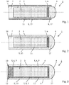
- the Figures 1 and 2 show schematic representations of luminous bodies 1 according to the invention. These are self-sufficient, permanently luminous bodies 1 which are generally rotationally symmetrical.
- the core piece is a tritium gas light source (GTLS) designed as a glass capsule 2, as is commercially available in rod-shaped, closed structures and is described at the beginning.
- GTLS tritium gas light source
- Each GTLS glass capsule 2 glows permanently in the dark for decades and can be clearly seen by the human eye as soon as it has gotten used to the darkness.
- a battery, nor a power source, nor any other energy supply, for example in the form of light is necessary for a GTLS glass capsule 2 to light up.
- a GTLS glass capsule 2 is permanently self-sufficient.
- a GTLS glass capsule 2 contains a radioactive gas which is released when the glass capsule breaks, it must be installed well protected in a housing in order to meet the legal requirements of most countries. For this reason, the GTLS glass capsule 2 is fixed in a sealed envelope 3 with a transparent viewing surface 4.
- the viewing surface 4 can be part of a transparent component 8, such as the outer surface of a lens 17, which is made of glass, ceramic or plastic, for example.
- This component 8 is on one End of a tubular sheath 3 attached sealingly, for example by a press fit.
- the sheath 3 can be made of metal or plastic, for example.
- the viewing surface 4 can be part of the shell 3, which is designed in one piece as a transparent tube closed on one side.
- the component 8 is thus molded onto the shell 3.
- the envelope 3 has an interior 11 and a closed, front end and an opposite open or rear end 10.
- the rear end 10 is only open for the production of the luminous element 1, after completion it is also closed, for example by means of a filler 7 with an adhesive.
- the GTLS glass capsule 2 is arranged in the closed interior 11 of the shell 3.
- a layer 6 offset with luminescent pigments 5 is arranged at least in the area between the GTLS glass capsule 2 and the viewing surface 4.
- the luminous element 1, viewed through the viewing surface 4 has a color such as green or blue, for example, and thus stands out better from the surroundings than a GTLS glass capsule 2, which is white in daylight.
- the pigments 5 are fluorescent, as a result of which the viewing surface 4 appears more strongly: the pigments are stimulated by the absorption of photons and deactivated again with the emission of light, which is known as photoluminescence.
- a second effect is achieved after the light has disappeared: Then the pigments 5 in the layer 6 continue to glow, so that these glow in addition to the GTLS glass capsule 2 for the next few minutes until the eye has got used to the darkness. After the luminosity of the pigments 5 has subsided, the GTLS glass capsule 2 continues to shine through the layer 6 with the pigments 5 and finally through the viewing surface 4, which does not lead to any noticeable reduction in the luminosity of the GTLS glass capsule 2.
- Such a luminous element 1 according to the invention is particularly suitable for identifying important points in the case of brightness and poor lighting conditions as well as in the dark. It can be easily built into instruments and devices 18 or attached to objects or locations that need to be able to be found quickly in emergency situations. For some applications it is advantageous if the user always perceives the luminosity of the luminous element 1 as being uniformly bright, although the dominance of the luminosity gradually changes from the afterglow pigments 5 to the GTLS 2 after the light has failed. For this purpose, afterglow pigments 5 must be used which, depending on the desired initial brightness and transition time from the afterglow pigment to the GTLS, afterglow for about 15 minutes to several hours.
- Photoluminescence preferably comprising strontium aluminate (SrAl 2 O 4 ), is preferably used as afterglow pigments 5.
- strontium aluminate SrAl 2 O 4
- Afterglow pigments 5 Various long-afterglow pigments 5 with different colors and afterglow times are available on the market, for example under the name Super-LumiNova® from RC-Tritec AG, Switzerland or LumiNova® from Nemoto & Co. Ltd., Japan. These and others continue to glow for a very long time and are therefore well suited for the luminous element 1 according to the invention.
- the afterglow pigments 5 can be mixed with a mass and processed into a rod of the desired diameter, from which thin slices, which form the layers 6, are finally cut off.
- a layer 6 is arranged in the envelope 3 on the inside of the viewing surface 4 before the GTLS glass capsule 2 is introduced behind it. It is important that the layer 6 is arranged between the viewing surface 4 and the GTLS glass capsule 2.
- the shell 3 is tightly closed at its open end 10 so that the pigments 5 in the interior 11 of the shell 3 remain protected from moisture and both the layer 6 and the GTLS glass capsule 2 remain fixed.
- the GTLS glass capsule 2 is surrounded by a filler 7 within the shell 3.
- This filler 7 dampens tensions between the GTLS glass capsule 2 and the shell 3, as a result of which glass breakage of the GTLS glass capsule 2 in the event of temperature changes or when vibrations occur can be largely prevented.
- the filler 7 preferably comprises an adhesive, so that the shell 3 is closed directly by the filler 7. It is sufficient if the adhesive is about 5-10 vol. % of the filler 7 makes up. In some cases the amount is also reduced to around 20 vol. % or more increased.
- the filler 7 of the luminous element 1 can be mixed with the afterglow pigments 5.
- the GTLS glass capsule 2 is surrounded on all sides by pigments 5.
- the layer 6 is formed by the filler 7 mixed with the pigments 5 and the adhesive.
- the pigments 5 decompose quickly on contact with moisture .
- the phosphors on the inner wall of the GTLS glass capsule have to be densely packed in a single layer of about 10 ⁇ m so that the electrons emitted by the tritium gas can generate the photons in this layer and so that these photons can escape through the glass. Another layer above or below the phosphors would shade this process and therefore greatly reduce it.
- the pigments 5 therefore cannot be mixed with the phosphors and cannot be applied to the inner surface on top of one another.
- a glass is often used as the glass capsule 2 which has a low optical transmittance in the UV-A spectrum, as a result of which any pigments 5 within the GTLS glass capsule 2 can hardly be charged with energy. Since the GTLS glass capsules 2 are filled with radioactive gas, the escape of which is highly undesirable, no arbitrary glass can be used for this.
- the pigments 5 outside the GTLS glass bodies 2 hardly darken the permanent light in the dark because they are less densely packed and surrounded by a transparent filler.
- the commercially available GTLS glass capsules 2 are generally designed as elongated tubes, so the casings 3 also preferably have a cylindrical wall 9.
- the concentric arrangement of the GTLS glass capsules 2 in the shells 3 means that the filler 7 has a uniform thickness around the outer surface of the GTLS glass capsule 2.
- the envelope 3 is made of glass, in particular made of sapphire glass, ceramic or plastic. If the shell 3 is completely transparent, its entire surface can absorb energy in the form of light, in particular UV light, which is stored in the afterglow pigments 5 and later given off again as light. This enlarges the viewing area 4.
- Such luminous bodies 1 are particularly well suited to being attached with their cylindrical walls 9 lying on a base, for example to generate an information sign such as a surface designed as an arrow.
- the luminous bodies 1 can also be attached to reflectors, as are known from office lamps.
- the rear sides of the luminous bodies 1 can also absorb and emit light.
- the rear, formerly open end 10 of the envelope 3 is sealed, for example with an adhesive, with glass, ceramic or with plastic.
- the cover 3 can be provided with a light-reflecting layer 12 on the surface which is arranged opposite the viewing surface 4. As a result, the light emitted to the rear is reflected back to the front, in the direction of the viewing surface 4. In addition, light incident from the outside through the viewing surface 4 is also reflected and thus increases the visibility of the luminous element 1.
- the luminous element 1 is used as a point of light, for example in instruments or devices 18, it is introduced into a bore 19 provided for this purpose in the device 18, as in FIG Fig. 4 shown.
- the viewing area 4 is then usually the closed, front end of the casing 3 designed as a tube.
- a luminous element 1 can optionally be used Fig. 1, 2 or 3 are used, the remarks according to Figs. 1 and 3 can also be combined.
- the envelope 3 of the luminous element 1 has an outer surface 13 which leaves out the viewing area 4. This is preferably covered at least partially with a light-reflecting casing 14 in order to optimize the light effect.
- a desired light reflection can be achieved, for example, by a thin, vapor-deposited layer 14 made of silver, gold, aluminum or chromium.
- a thicker layer such as a shrink tube, which has a reflective inner surface, can be used as the sheathing 14.
- Such a casing 14 also acts as a damping mat between the luminous element 1 and the device 18, in the bore 19 of which it is installed, in order to avoid damage caused by mechanical or thermal stresses or by vibrations.
- the casing 14 can also have a second recess 15 which, in the installed state, allows light 16 of an external light to be incident if this is provided accordingly in the device 18. If the installation position of the luminous element 1 is provided far away from the edge of the device 18, light can be guided through one or more light guides from the device edge to the second recess 15 (not shown). Thanks to this additional incidence of light, more energy can be stored in the afterglowing pigments 5, as a result of which the luminosity is increased.
- the cover 3 can be configured to form a lens 17, in particular a diffusing or collecting lens.
- the viewing areas 4 after Figs. 1, 2, 3 and 4th are designed as converging lenses.
- the viewing area 4 is designed flat.
- the luminous element 1 can be installed completely in a bore 19 and the viewing surface 4 ends flush with the device wall 18. So no dirt collects around the viewing surface 4 and the luminous element 1 is also well protected from mechanical influences.
- the contour of the interior 11 in the direction of the planar viewing surface 4 can, as in FIG Figure 5a shown, be configured convex, whereby a convex-planar converging lens 17 is formed.
- the interior space 11 is designed to be concave in the direction of the planar viewing surface 4, as a result of which a concave-planar scattering lens 17 is formed.
- Fig. 6 is a further application example for the inventive luminous element 1 according to FIG. Fig. 3 shown.
- the viewing surface 4 thus comprises at least the cylindrical wall 9 of the luminous element 1.
- the luminous element 1 also comprises a fastening device 20 to which it can be attached to an object that has to be found quickly in emergency situations.
- This fastening device 20 can, for example, be a hole through the sleeve 3 through which a key ring, a mounting strap or the like can be passed.
- the casing 3 is made of plastic, for example, and extends on one side of the GTLS glass capsule 2 for a sufficient length so as not to endanger it breaking.
- an eyelet can be formed on an end piece which is attached to the luminous element 1, for example by means of an adhesive or by means of a clamp.
- Fig. 1 an execution according to Fig. 1 can be used in which the tube 3 used, open on both sides, is transparent and forms the viewing surface 4.
- the component 8 does not necessarily have to be be transparent. It can be attached on one or both sides and contain the fastening device 20.
- the pigments 5 can in turn be mixed with a filler 7 which surrounds the GTLS glass capsule 2.
- an in Fig. 1 Disc 6 described with the pigments 5 are wrapped around the GTLS glass capsule 2.
Landscapes
- Engineering & Computer Science (AREA)
- Physics & Mathematics (AREA)
- General Engineering & Computer Science (AREA)
- Electromagnetism (AREA)
- Plasma & Fusion (AREA)
- Spectroscopy & Molecular Physics (AREA)
- Non-Portable Lighting Devices Or Systems Thereof (AREA)
- Illuminated Signs And Luminous Advertising (AREA)
- Vessels And Coating Films For Discharge Lamps (AREA)
Claims (14)
- Corps autonome en permanence lumineux (1) pour identification de points importants concernant la luminosité, les mauvaises conditions de lumière ainsi que concernant l'obscurité, en particulier pour l'incorporation dans des instruments (18) ou pour le montage sur des objets, qui doivent être rapidement détectés dans des situations d'urgence, comprenant une source lumineuse au tritium gazeux (GTLS) (2), se présentant sous la forme d'une capsule de gaz, laquelle est fixée dans une enveloppe (3) avec une surface d'observation (4) transparente, caractérisé en ce qu'au moins une couche (6) déplacée avec des pigments phosphorescents (5) est disposée entre la capsule de gaz GTLS (2) et la surface d'observation (4).
- Corps lumineux (1) selon la revendication 1, caractérisé en ce que les pigments phosphorescents (5) sont des photoluminescences, de préférence comprenant de l'aluminate de strontium (SrAl2O4).
- Corps lumineux (1) selon la revendication 1 ou 2, caractérisé en ce que la capsule de gaz GTLS (2) à l'intérieur de l'enveloppe (3) est entourée d'une substance de remplissage (7).
- Corps lumineux (1) selon la revendication 3, caractérisé en ce que la substance de remplissage (7) comprend un adhésif, lequel représente de préférence une partie d'au moins 5 % /vol de la substance de remplissage (7).
- Corps lumineux (1) selon la revendication 3 ou 4, caractérisé en ce que la substance de remplissage (7) est déplacée avec les pigments phosphorescents (5).
- Corps lumineux (1) selon l'une quelconque des revendications précédentes, caractérisé en ce que l'enveloppe (3) se présente avec une paroi cylindrique (9) .
- Corps lumineux (1) selon l'une quelconque des revendications précédentes, caractérisé en ce que l'enveloppe (3) est en verre, verre en saphir, céramique ou matière plastique.
- Corps lumineux (1) selon l'une quelconque des revendications précédentes, caractérisé en ce que l'enveloppe (3) est scellée, de préférence avec un adhésif, avec du verre, de la céramique ou avec de la matière plastique.
- Corps lumineux (1) selon l'une quelconque des revendications précédentes, caractérisé en ce qu'il est doté d'une couche (12) réfléchissant la lumière par rapport à la surface d'observation (4).
- Corps lumineux (1) selon l'une quelconque des revendications précédentes, caractérisé en ce que l'enveloppe (3) comporte une surface (13) extérieure ménageant la surface d'observation (4), laquelle est couverte au moins en partie avec un revêtement (14) réfléchissant la lumière.
- Corps lumineux (1) selon la revendication 10, caractérisé en ce que le revêtement (14) comporte un deuxième évidement (15) en plus de l'évidement pour la surface d'observation (4), lequel permet à l'état monté une incidence de la lumière (16) d'une lumière extérieure.
- Corps lumineux (1) selon l'une quelconque des revendications précédentes, caractérisé en ce que l'enveloppe (3) se présente dans la zone de la surface d'observation (4) sous la forme d'une lentille (17), en particulier sous la forme d'une lentille divergente ou convergente.
- Corps lumineux (1) selon l'une quelconque des revendications précédentes, caractérisé en ce que la surface d'observation (4) se présente plane.
- Corps lumineux (1) selon l'une quelconque des revendications précédentes, caractérisé en ce que l'enveloppe (3) comporte un dispositif de fixation (20) pour montage sur un objet.
Priority Applications (2)
| Application Number | Priority Date | Filing Date | Title |
|---|---|---|---|
| HRP20210282TT HRP20210282T1 (hr) | 2017-01-24 | 2018-01-09 | Svjetleće tijelo |
| RS20210177A RS61445B1 (sr) | 2017-01-24 | 2018-01-09 | Svetleće telo |
Applications Claiming Priority (2)
| Application Number | Priority Date | Filing Date | Title |
|---|---|---|---|
| CH00075/17A CH713382A1 (de) | 2017-01-24 | 2017-01-24 | Leuchtkörper. |
| PCT/EP2018/050406 WO2018137918A1 (fr) | 2017-01-24 | 2018-01-09 | Corps d'éclairage |
Publications (2)
| Publication Number | Publication Date |
|---|---|
| EP3574253A1 EP3574253A1 (fr) | 2019-12-04 |
| EP3574253B1 true EP3574253B1 (fr) | 2020-12-02 |
Family
ID=57914607
Family Applications (1)
| Application Number | Title | Priority Date | Filing Date |
|---|---|---|---|
| EP18700401.5A Active EP3574253B1 (fr) | 2017-01-24 | 2018-01-09 | Corps d'éclairage |
Country Status (10)
| Country | Link |
|---|---|
| US (1) | US10415761B2 (fr) |
| EP (1) | EP3574253B1 (fr) |
| KR (1) | KR20190110571A (fr) |
| CN (1) | CN110214246A (fr) |
| CA (1) | CA3049482A1 (fr) |
| CH (1) | CH713382A1 (fr) |
| HR (1) | HRP20210282T1 (fr) |
| IL (1) | IL267586B (fr) |
| RS (1) | RS61445B1 (fr) |
| WO (1) | WO2018137918A1 (fr) |
Families Citing this family (1)
| Publication number | Priority date | Publication date | Assignee | Title |
|---|---|---|---|---|
| CN109163301A (zh) * | 2018-10-18 | 2019-01-08 | 华域视觉科技(上海)有限公司 | 无源发光光源、制备方法及车灯 |
Family Cites Families (13)
| Publication number | Priority date | Publication date | Assignee | Title |
|---|---|---|---|---|
| DE1113752B (de) * | 1960-04-26 | 1961-09-14 | Trilux Lenze Gmbh & Co Kg | Verfahren zur Herstellung von selbstleuchtenden Lichtquellen |
| US4935632A (en) * | 1985-09-23 | 1990-06-19 | Landus Inc. | Luminescent concentrator light source |
| US4990804A (en) * | 1989-10-10 | 1991-02-05 | Mcnair Rhett C | Self-luminous light source |
| JP3040105U (ja) * | 1997-01-31 | 1997-08-15 | 日本化学発光株式会社 | 変形自在な化学発光体 |
| US6062380A (en) * | 1998-05-18 | 2000-05-16 | Dorney; Peter | Glow cup system |
| US6776495B2 (en) * | 2002-01-23 | 2004-08-17 | Lumica Corporation | Chemiluminescent device |
| CN100410703C (zh) * | 2004-03-12 | 2008-08-13 | 艾利丹尼森公司 | 具有被动磷光光源的照明系统 |
| US20110120459A1 (en) * | 2009-11-20 | 2011-05-26 | Omniglow Llc | Illuminated endotracheal stylet |
| EP2626401B1 (fr) * | 2012-02-10 | 2016-10-05 | Rolex Sa | Nouveaux luminophores à longue période d'extinction |
| AT513324B1 (de) * | 2012-08-28 | 2015-01-15 | Mb Microtec Ag | Verfahren zur Herstellung eines selbstleuchtenden Körpers und selbstleuchtender Körper |
| CN204083826U (zh) * | 2014-07-11 | 2015-01-07 | 北京文海阳工贸有限责任公司 | 一种发光球 |
| US9279553B1 (en) | 2014-09-26 | 2016-03-08 | Orion Energy Systems, Inc. | Periphery-lit troffer light fixture retrofit systems and methods |
| JP6138743B2 (ja) * | 2014-11-05 | 2017-05-31 | 株式会社ルミカ | 化学発光体 |
-
2017
- 2017-01-24 CH CH00075/17A patent/CH713382A1/de not_active Application Discontinuation
-
2018
- 2018-01-09 EP EP18700401.5A patent/EP3574253B1/fr active Active
- 2018-01-09 HR HRP20210282TT patent/HRP20210282T1/hr unknown
- 2018-01-09 US US16/319,711 patent/US10415761B2/en active Active
- 2018-01-09 CA CA3049482A patent/CA3049482A1/fr not_active Abandoned
- 2018-01-09 RS RS20210177A patent/RS61445B1/sr unknown
- 2018-01-09 KR KR1020197024260A patent/KR20190110571A/ko not_active Ceased
- 2018-01-09 WO PCT/EP2018/050406 patent/WO2018137918A1/fr not_active Ceased
- 2018-01-09 CN CN201880007908.1A patent/CN110214246A/zh active Pending
-
2019
- 2019-06-23 IL IL267586A patent/IL267586B/en active IP Right Grant
Non-Patent Citations (1)
| Title |
|---|
| None * |
Also Published As
| Publication number | Publication date |
|---|---|
| CA3049482A1 (fr) | 2018-08-02 |
| IL267586B (en) | 2021-01-31 |
| CN110214246A (zh) | 2019-09-06 |
| RS61445B1 (sr) | 2021-03-31 |
| EP3574253A1 (fr) | 2019-12-04 |
| KR20190110571A (ko) | 2019-09-30 |
| US10415761B2 (en) | 2019-09-17 |
| HRP20210282T1 (hr) | 2021-04-02 |
| CH713382A1 (de) | 2018-07-31 |
| IL267586A (en) | 2019-08-29 |
| US20190242530A1 (en) | 2019-08-08 |
| WO2018137918A1 (fr) | 2018-08-02 |
Similar Documents
| Publication | Publication Date | Title |
|---|---|---|
| EP2507579B1 (fr) | Dispositif de viseur | |
| EP2350733B1 (fr) | Dispositif de visée | |
| EP0125476A2 (fr) | Eclairage d'instruments | |
| EP3574253A1 (fr) | Corps d'éclairage | |
| DE212011100018U1 (de) | Leuchtvorrichtung mit einem Grundkörper aus lichtdurchlässigem Material | |
| DE102010060914A1 (de) | Chirurgisches Markerelement, chirurgische Referenzierungseinheit und chirurgisches Navigationssystem | |
| DE102017201676B4 (de) | Uhrglas mit lumineszierendem Element | |
| DE4340709B4 (de) | Anzeigeeinrichtung | |
| DE29820384U1 (de) | Leucht- oder Anzeigeelement mit mischfarbigen, insbesondere weißem Licht | |
| DE10030532C1 (de) | Leuchte mit einem nachleuchtenden Abdeckelement | |
| DE880692C (de) | Blitzlichtlampe | |
| DE949627C (de) | Reflexisier | |
| DE102006032457B4 (de) | Hintergrundbeleuchtung mittels nichtelektrischer Eneregiequellen | |
| DE202017104072U1 (de) | Zielvorrichtung | |
| EP4348614B1 (fr) | Élément d'éclairage d'urgence | |
| CH318892A (de) | Reflexvisier | |
| DE102007018287B4 (de) | Zeiger für eine Uhr | |
| DE202013101400U1 (de) | Anordnung zum Konvertieren des von einer LED-Lichtquelle emittierten Lichts | |
| AT15905U1 (de) | Leuchtkörper | |
| DE102012001143A1 (de) | Beleuchtungsvorrichtung zur blendfreien Beleuchtung, Verfahren, Verwendung sowie Anordnung mit der Beleuchtungsvorrichtung | |
| DE102022108996A1 (de) | Lichtleitelement beispielsweise für rettungszeichenleuchte | |
| DE29805052U1 (de) | Leuchtrahmen | |
| DE9105945U1 (de) | Fluoreszierende Anzeigeeinrichtung | |
| DE202013006964U1 (de) | Ringschiene für leuchtende, idealerweise chemolumineszierende, Gravuren | |
| DEC0008665MA (fr) |
Legal Events
| Date | Code | Title | Description |
|---|---|---|---|
| STAA | Information on the status of an ep patent application or granted ep patent |
Free format text: STATUS: UNKNOWN |
|
| STAA | Information on the status of an ep patent application or granted ep patent |
Free format text: STATUS: THE INTERNATIONAL PUBLICATION HAS BEEN MADE |
|
| PUAI | Public reference made under article 153(3) epc to a published international application that has entered the european phase |
Free format text: ORIGINAL CODE: 0009012 |
|
| STAA | Information on the status of an ep patent application or granted ep patent |
Free format text: STATUS: REQUEST FOR EXAMINATION WAS MADE |
|
| 17P | Request for examination filed |
Effective date: 20190701 |
|
| AK | Designated contracting states |
Kind code of ref document: A1 Designated state(s): AL AT BE BG CH CY CZ DE DK EE ES FI FR GB GR HR HU IE IS IT LI LT LU LV MC MK MT NL NO PL PT RO RS SE SI SK SM TR |
|
| AX | Request for extension of the european patent |
Extension state: BA ME |
|
| DAV | Request for validation of the european patent (deleted) | ||
| DAX | Request for extension of the european patent (deleted) | ||
| REG | Reference to a national code |
Ref country code: HK Ref legal event code: DE Ref document number: 40010138 Country of ref document: HK |
|
| GRAP | Despatch of communication of intention to grant a patent |
Free format text: ORIGINAL CODE: EPIDOSNIGR1 |
|
| STAA | Information on the status of an ep patent application or granted ep patent |
Free format text: STATUS: GRANT OF PATENT IS INTENDED |
|
| RIC1 | Information provided on ipc code assigned before grant |
Ipc: F21K 2/00 20060101AFI20200615BHEP Ipc: H01J 65/08 20060101ALI20200615BHEP Ipc: H01J 61/38 20060101ALI20200615BHEP |
|
| INTG | Intention to grant announced |
Effective date: 20200708 |
|
| GRAS | Grant fee paid |
Free format text: ORIGINAL CODE: EPIDOSNIGR3 |
|
| GRAA | (expected) grant |
Free format text: ORIGINAL CODE: 0009210 |
|
| STAA | Information on the status of an ep patent application or granted ep patent |
Free format text: STATUS: THE PATENT HAS BEEN GRANTED |
|
| AK | Designated contracting states |
Kind code of ref document: B1 Designated state(s): AL AT BE BG CH CY CZ DE DK EE ES FI FR GB GR HR HU IE IS IT LI LT LU LV MC MK MT NL NO PL PT RO RS SE SI SK SM TR |
|
| REG | Reference to a national code |
Ref country code: GB Ref legal event code: FG4D Free format text: NOT ENGLISH |
|
| REG | Reference to a national code |
Ref country code: AT Ref legal event code: REF Ref document number: 1341312 Country of ref document: AT Kind code of ref document: T Effective date: 20201215 Ref country code: CH Ref legal event code: EP |
|
| REG | Reference to a national code |
Ref country code: DE Ref legal event code: R096 Ref document number: 502018003180 Country of ref document: DE |
|
| REG | Reference to a national code |
Ref country code: IE Ref legal event code: FG4D Free format text: LANGUAGE OF EP DOCUMENT: GERMAN |
|
| REG | Reference to a national code |
Ref country code: CH Ref legal event code: NV Representative=s name: KELLER SCHNEIDER PATENT- UND MARKENANWAELTE AG, CH |
|
| REG | Reference to a national code |
Ref country code: HR Ref legal event code: TUEP Ref document number: P20210282 Country of ref document: HR |
|
| REG | Reference to a national code |
Ref country code: HR Ref legal event code: ODRP Ref document number: P20210282 Country of ref document: HR Payment date: 20210218 Year of fee payment: 4 |
|
| REG | Reference to a national code |
Ref country code: HR Ref legal event code: T1PR Ref document number: P20210282 Country of ref document: HR |
|
| PG25 | Lapsed in a contracting state [announced via postgrant information from national office to epo] |
Ref country code: FI Free format text: LAPSE BECAUSE OF FAILURE TO SUBMIT A TRANSLATION OF THE DESCRIPTION OR TO PAY THE FEE WITHIN THE PRESCRIBED TIME-LIMIT Effective date: 20201202 Ref country code: NO Free format text: LAPSE BECAUSE OF FAILURE TO SUBMIT A TRANSLATION OF THE DESCRIPTION OR TO PAY THE FEE WITHIN THE PRESCRIBED TIME-LIMIT Effective date: 20210302 Ref country code: GR Free format text: LAPSE BECAUSE OF FAILURE TO SUBMIT A TRANSLATION OF THE DESCRIPTION OR TO PAY THE FEE WITHIN THE PRESCRIBED TIME-LIMIT Effective date: 20210303 |
|
| REG | Reference to a national code |
Ref country code: NL Ref legal event code: MP Effective date: 20201202 |
|
| PG25 | Lapsed in a contracting state [announced via postgrant information from national office to epo] |
Ref country code: SE Free format text: LAPSE BECAUSE OF FAILURE TO SUBMIT A TRANSLATION OF THE DESCRIPTION OR TO PAY THE FEE WITHIN THE PRESCRIBED TIME-LIMIT Effective date: 20201202 Ref country code: LV Free format text: LAPSE BECAUSE OF FAILURE TO SUBMIT A TRANSLATION OF THE DESCRIPTION OR TO PAY THE FEE WITHIN THE PRESCRIBED TIME-LIMIT Effective date: 20201202 Ref country code: PL Free format text: LAPSE BECAUSE OF FAILURE TO SUBMIT A TRANSLATION OF THE DESCRIPTION OR TO PAY THE FEE WITHIN THE PRESCRIBED TIME-LIMIT Effective date: 20201202 Ref country code: BG Free format text: LAPSE BECAUSE OF FAILURE TO SUBMIT A TRANSLATION OF THE DESCRIPTION OR TO PAY THE FEE WITHIN THE PRESCRIBED TIME-LIMIT Effective date: 20210302 |
|
| PG25 | Lapsed in a contracting state [announced via postgrant information from national office to epo] |
Ref country code: NL Free format text: LAPSE BECAUSE OF FAILURE TO SUBMIT A TRANSLATION OF THE DESCRIPTION OR TO PAY THE FEE WITHIN THE PRESCRIBED TIME-LIMIT Effective date: 20201202 |
|
| REG | Reference to a national code |
Ref country code: LT Ref legal event code: MG9D |
|
| PG25 | Lapsed in a contracting state [announced via postgrant information from national office to epo] |
Ref country code: LT Free format text: LAPSE BECAUSE OF FAILURE TO SUBMIT A TRANSLATION OF THE DESCRIPTION OR TO PAY THE FEE WITHIN THE PRESCRIBED TIME-LIMIT Effective date: 20201202 Ref country code: RO Free format text: LAPSE BECAUSE OF FAILURE TO SUBMIT A TRANSLATION OF THE DESCRIPTION OR TO PAY THE FEE WITHIN THE PRESCRIBED TIME-LIMIT Effective date: 20201202 Ref country code: PT Free format text: LAPSE BECAUSE OF FAILURE TO SUBMIT A TRANSLATION OF THE DESCRIPTION OR TO PAY THE FEE WITHIN THE PRESCRIBED TIME-LIMIT Effective date: 20210405 Ref country code: SK Free format text: LAPSE BECAUSE OF FAILURE TO SUBMIT A TRANSLATION OF THE DESCRIPTION OR TO PAY THE FEE WITHIN THE PRESCRIBED TIME-LIMIT Effective date: 20201202 Ref country code: SM Free format text: LAPSE BECAUSE OF FAILURE TO SUBMIT A TRANSLATION OF THE DESCRIPTION OR TO PAY THE FEE WITHIN THE PRESCRIBED TIME-LIMIT Effective date: 20201202 Ref country code: EE Free format text: LAPSE BECAUSE OF FAILURE TO SUBMIT A TRANSLATION OF THE DESCRIPTION OR TO PAY THE FEE WITHIN THE PRESCRIBED TIME-LIMIT Effective date: 20201202 |
|
| REG | Reference to a national code |
Ref country code: DE Ref legal event code: R097 Ref document number: 502018003180 Country of ref document: DE |
|
| PG25 | Lapsed in a contracting state [announced via postgrant information from national office to epo] |
Ref country code: MC Free format text: LAPSE BECAUSE OF FAILURE TO SUBMIT A TRANSLATION OF THE DESCRIPTION OR TO PAY THE FEE WITHIN THE PRESCRIBED TIME-LIMIT Effective date: 20201202 Ref country code: LU Free format text: LAPSE BECAUSE OF NON-PAYMENT OF DUE FEES Effective date: 20210109 Ref country code: IS Free format text: LAPSE BECAUSE OF FAILURE TO SUBMIT A TRANSLATION OF THE DESCRIPTION OR TO PAY THE FEE WITHIN THE PRESCRIBED TIME-LIMIT Effective date: 20210402 |
|
| REG | Reference to a national code |
Ref country code: BE Ref legal event code: MM Effective date: 20210131 |
|
| PLBE | No opposition filed within time limit |
Free format text: ORIGINAL CODE: 0009261 |
|
| STAA | Information on the status of an ep patent application or granted ep patent |
Free format text: STATUS: NO OPPOSITION FILED WITHIN TIME LIMIT |
|
| PG25 | Lapsed in a contracting state [announced via postgrant information from national office to epo] |
Ref country code: AL Free format text: LAPSE BECAUSE OF FAILURE TO SUBMIT A TRANSLATION OF THE DESCRIPTION OR TO PAY THE FEE WITHIN THE PRESCRIBED TIME-LIMIT Effective date: 20201202 |
|
| 26N | No opposition filed |
Effective date: 20210903 |
|
| PG25 | Lapsed in a contracting state [announced via postgrant information from national office to epo] |
Ref country code: DK Free format text: LAPSE BECAUSE OF FAILURE TO SUBMIT A TRANSLATION OF THE DESCRIPTION OR TO PAY THE FEE WITHIN THE PRESCRIBED TIME-LIMIT Effective date: 20201202 Ref country code: SI Free format text: LAPSE BECAUSE OF FAILURE TO SUBMIT A TRANSLATION OF THE DESCRIPTION OR TO PAY THE FEE WITHIN THE PRESCRIBED TIME-LIMIT Effective date: 20201202 |
|
| REG | Reference to a national code |
Ref country code: HR Ref legal event code: ODRP Ref document number: P20210282 Country of ref document: HR Payment date: 20211231 Year of fee payment: 5 |
|
| PG25 | Lapsed in a contracting state [announced via postgrant information from national office to epo] |
Ref country code: IE Free format text: LAPSE BECAUSE OF NON-PAYMENT OF DUE FEES Effective date: 20210109 Ref country code: ES Free format text: LAPSE BECAUSE OF FAILURE TO SUBMIT A TRANSLATION OF THE DESCRIPTION OR TO PAY THE FEE WITHIN THE PRESCRIBED TIME-LIMIT Effective date: 20201202 |
|
| PGFP | Annual fee paid to national office [announced via postgrant information from national office to epo] |
Ref country code: HR Payment date: 20211231 Year of fee payment: 5 Ref country code: CZ Payment date: 20211215 Year of fee payment: 5 Ref country code: RS Payment date: 20211209 Year of fee payment: 5 Ref country code: FR Payment date: 20211217 Year of fee payment: 5 |
|
| PG25 | Lapsed in a contracting state [announced via postgrant information from national office to epo] |
Ref country code: IS Free format text: LAPSE BECAUSE OF FAILURE TO SUBMIT A TRANSLATION OF THE DESCRIPTION OR TO PAY THE FEE WITHIN THE PRESCRIBED TIME-LIMIT Effective date: 20210402 |
|
| PG25 | Lapsed in a contracting state [announced via postgrant information from national office to epo] |
Ref country code: BE Free format text: LAPSE BECAUSE OF NON-PAYMENT OF DUE FEES Effective date: 20210131 |
|
| PGFP | Annual fee paid to national office [announced via postgrant information from national office to epo] |
Ref country code: GB Payment date: 20221208 Year of fee payment: 6 |
|
| PGFP | Annual fee paid to national office [announced via postgrant information from national office to epo] |
Ref country code: IT Payment date: 20221213 Year of fee payment: 6 Ref country code: DE Payment date: 20221207 Year of fee payment: 6 |
|
| PG25 | Lapsed in a contracting state [announced via postgrant information from national office to epo] |
Ref country code: CY Free format text: LAPSE BECAUSE OF FAILURE TO SUBMIT A TRANSLATION OF THE DESCRIPTION OR TO PAY THE FEE WITHIN THE PRESCRIBED TIME-LIMIT Effective date: 20201202 |
|
| REG | Reference to a national code |
Ref country code: HR Ref legal event code: PBON Ref document number: P20210282 Country of ref document: HR Effective date: 20230109 |
|
| PG25 | Lapsed in a contracting state [announced via postgrant information from national office to epo] |
Ref country code: HU Free format text: LAPSE BECAUSE OF FAILURE TO SUBMIT A TRANSLATION OF THE DESCRIPTION OR TO PAY THE FEE WITHIN THE PRESCRIBED TIME-LIMIT; INVALID AB INITIO Effective date: 20180109 Ref country code: CZ Free format text: LAPSE BECAUSE OF NON-PAYMENT OF DUE FEES Effective date: 20230109 |
|
| PG25 | Lapsed in a contracting state [announced via postgrant information from national office to epo] |
Ref country code: RS Free format text: LAPSE BECAUSE OF NON-PAYMENT OF DUE FEES Effective date: 20230717 Ref country code: HR Free format text: LAPSE BECAUSE OF NON-PAYMENT OF DUE FEES Effective date: 20230109 Ref country code: FR Free format text: LAPSE BECAUSE OF NON-PAYMENT OF DUE FEES Effective date: 20230131 |
|
| REG | Reference to a national code |
Ref country code: AT Ref legal event code: MM01 Ref document number: 1341312 Country of ref document: AT Kind code of ref document: T Effective date: 20230109 |
|
| PG25 | Lapsed in a contracting state [announced via postgrant information from national office to epo] |
Ref country code: AT Free format text: LAPSE BECAUSE OF NON-PAYMENT OF DUE FEES Effective date: 20230109 |
|
| PG25 | Lapsed in a contracting state [announced via postgrant information from national office to epo] |
Ref country code: MK Free format text: LAPSE BECAUSE OF FAILURE TO SUBMIT A TRANSLATION OF THE DESCRIPTION OR TO PAY THE FEE WITHIN THE PRESCRIBED TIME-LIMIT Effective date: 20201202 Ref country code: AT Free format text: LAPSE BECAUSE OF NON-PAYMENT OF DUE FEES Effective date: 20230109 |
|
| REG | Reference to a national code |
Ref country code: DE Ref legal event code: R119 Ref document number: 502018003180 Country of ref document: DE |
|
| GBPC | Gb: european patent ceased through non-payment of renewal fee |
Effective date: 20240109 |
|
| PG25 | Lapsed in a contracting state [announced via postgrant information from national office to epo] |
Ref country code: MT Free format text: LAPSE BECAUSE OF FAILURE TO SUBMIT A TRANSLATION OF THE DESCRIPTION OR TO PAY THE FEE WITHIN THE PRESCRIBED TIME-LIMIT Effective date: 20201202 |
|
| PG25 | Lapsed in a contracting state [announced via postgrant information from national office to epo] |
Ref country code: DE Free format text: LAPSE BECAUSE OF NON-PAYMENT OF DUE FEES Effective date: 20240801 |
|
| PG25 | Lapsed in a contracting state [announced via postgrant information from national office to epo] |
Ref country code: GB Free format text: LAPSE BECAUSE OF NON-PAYMENT OF DUE FEES Effective date: 20240109 |
|
| PG25 | Lapsed in a contracting state [announced via postgrant information from national office to epo] |
Ref country code: GB Free format text: LAPSE BECAUSE OF NON-PAYMENT OF DUE FEES Effective date: 20240109 Ref country code: DE Free format text: LAPSE BECAUSE OF NON-PAYMENT OF DUE FEES Effective date: 20240801 |
|
| PG25 | Lapsed in a contracting state [announced via postgrant information from national office to epo] |
Ref country code: IT Free format text: LAPSE BECAUSE OF NON-PAYMENT OF DUE FEES Effective date: 20240109 |
|
| PG25 | Lapsed in a contracting state [announced via postgrant information from national office to epo] |
Ref country code: TR Free format text: LAPSE BECAUSE OF FAILURE TO SUBMIT A TRANSLATION OF THE DESCRIPTION OR TO PAY THE FEE WITHIN THE PRESCRIBED TIME-LIMIT Effective date: 20201202 |
|
| REG | Reference to a national code |
Ref country code: CH Ref legal event code: U11 Free format text: ST27 STATUS EVENT CODE: U-0-0-U10-U11 (AS PROVIDED BY THE NATIONAL OFFICE) Effective date: 20260201 |
|
| PGFP | Annual fee paid to national office [announced via postgrant information from national office to epo] |
Ref country code: AT Payment date: 20260410 Year of fee payment: 5 |
|
| PGFP | Annual fee paid to national office [announced via postgrant information from national office to epo] |
Ref country code: CH Payment date: 20260201 Year of fee payment: 9 |