EP3574337B1 - Doppelfrequenz-fmcw-lidar und verfahren - Google Patents
Doppelfrequenz-fmcw-lidar und verfahren Download PDFInfo
- Publication number
- EP3574337B1 EP3574337B1 EP17893678.7A EP17893678A EP3574337B1 EP 3574337 B1 EP3574337 B1 EP 3574337B1 EP 17893678 A EP17893678 A EP 17893678A EP 3574337 B1 EP3574337 B1 EP 3574337B1
- Authority
- EP
- European Patent Office
- Prior art keywords
- frequency
- waveguide
- radiation
- laser radiation
- modulated laser
- Prior art date
- Legal status (The legal status is an assumption and is not a legal conclusion. Google has not performed a legal analysis and makes no representation as to the accuracy of the status listed.)
- Active
Links
Images


Classifications
-
- H—ELECTRICITY
- H04—ELECTRIC COMMUNICATION TECHNIQUE
- H04L—TRANSMISSION OF DIGITAL INFORMATION, e.g. TELEGRAPHIC COMMUNICATION
- H04L27/00—Modulated-carrier systems
- H04L27/10—Frequency-modulated carrier systems, i.e. using frequency-shift keying
- H04L27/103—Chirp modulation
-
- G—PHYSICS
- G01—MEASURING; TESTING
- G01R—MEASURING ELECTRIC VARIABLES; MEASURING MAGNETIC VARIABLES
- G01R31/00—Arrangements for testing electric properties; Arrangements for locating electric faults; Arrangements for electrical testing characterised by what is being tested not provided for elsewhere
- G01R31/28—Testing of electronic circuits, e.g. by signal tracer
- G01R31/282—Testing of electronic circuits specially adapted for particular applications not provided for elsewhere
- G01R31/2829—Testing of circuits in sensor or actuator systems
-
- G—PHYSICS
- G01—MEASURING; TESTING
- G01S—RADIO DIRECTION-FINDING; RADIO NAVIGATION; DETERMINING DISTANCE OR VELOCITY BY USE OF RADIO WAVES; LOCATING OR PRESENCE-DETECTING BY USE OF THE REFLECTION OR RERADIATION OF RADIO WAVES; ANALOGOUS ARRANGEMENTS USING OTHER WAVES
- G01S17/00—Systems using the reflection or reradiation of electromagnetic waves other than radio waves, e.g. lidar systems
- G01S17/02—Systems using the reflection of electromagnetic waves other than radio waves
- G01S17/06—Systems determining position data of a target
- G01S17/08—Systems determining position data of a target for measuring distance only
- G01S17/32—Systems determining position data of a target for measuring distance only using transmission of continuous waves, whether amplitude-, frequency-, or phase-modulated, or unmodulated
- G01S17/34—Systems determining position data of a target for measuring distance only using transmission of continuous waves, whether amplitude-, frequency-, or phase-modulated, or unmodulated using transmission of continuous, frequency-modulated waves while heterodyning the received signal, or a signal derived therefrom, with a locally-generated signal related to the contemporaneously transmitted signal
-
- G—PHYSICS
- G01—MEASURING; TESTING
- G01S—RADIO DIRECTION-FINDING; RADIO NAVIGATION; DETERMINING DISTANCE OR VELOCITY BY USE OF RADIO WAVES; LOCATING OR PRESENCE-DETECTING BY USE OF THE REFLECTION OR RERADIATION OF RADIO WAVES; ANALOGOUS ARRANGEMENTS USING OTHER WAVES
- G01S17/00—Systems using the reflection or reradiation of electromagnetic waves other than radio waves, e.g. lidar systems
- G01S17/02—Systems using the reflection of electromagnetic waves other than radio waves
- G01S17/50—Systems of measurement based on relative movement of target
- G01S17/58—Velocity or trajectory determination systems; Sense-of-movement determination systems
-
- G—PHYSICS
- G01—MEASURING; TESTING
- G01S—RADIO DIRECTION-FINDING; RADIO NAVIGATION; DETERMINING DISTANCE OR VELOCITY BY USE OF RADIO WAVES; LOCATING OR PRESENCE-DETECTING BY USE OF THE REFLECTION OR RERADIATION OF RADIO WAVES; ANALOGOUS ARRANGEMENTS USING OTHER WAVES
- G01S7/00—Details of systems according to groups G01S13/00, G01S15/00, G01S17/00
- G01S7/48—Details of systems according to groups G01S13/00, G01S15/00, G01S17/00 of systems according to group G01S17/00
- G01S7/481—Constructional features, e.g. arrangements of optical elements
- G01S7/4818—Constructional features, e.g. arrangements of optical elements using optical fibres
-
- G—PHYSICS
- G01—MEASURING; TESTING
- G01S—RADIO DIRECTION-FINDING; RADIO NAVIGATION; DETERMINING DISTANCE OR VELOCITY BY USE OF RADIO WAVES; LOCATING OR PRESENCE-DETECTING BY USE OF THE REFLECTION OR RERADIATION OF RADIO WAVES; ANALOGOUS ARRANGEMENTS USING OTHER WAVES
- G01S7/00—Details of systems according to groups G01S13/00, G01S15/00, G01S17/00
- G01S7/48—Details of systems according to groups G01S13/00, G01S15/00, G01S17/00 of systems according to group G01S17/00
- G01S7/491—Details of non-pulse systems
- G01S7/4912—Receivers
- G01S7/4917—Receivers superposing optical signals in a photodetector, e.g. optical heterodyne detection
-
- H—ELECTRICITY
- H04—ELECTRIC COMMUNICATION TECHNIQUE
- H04B—TRANSMISSION
- H04B10/00—Transmission systems employing electromagnetic waves other than radio-waves, e.g. infrared, visible or ultraviolet light, or employing corpuscular radiation, e.g. quantum communication
- H04B10/40—Transceivers
-
- H—ELECTRICITY
- H04—ELECTRIC COMMUNICATION TECHNIQUE
- H04B—TRANSMISSION
- H04B10/00—Transmission systems employing electromagnetic waves other than radio-waves, e.g. infrared, visible or ultraviolet light, or employing corpuscular radiation, e.g. quantum communication
- H04B10/50—Transmitters
-
- H—ELECTRICITY
- H04—ELECTRIC COMMUNICATION TECHNIQUE
- H04B—TRANSMISSION
- H04B10/00—Transmission systems employing electromagnetic waves other than radio-waves, e.g. infrared, visible or ultraviolet light, or employing corpuscular radiation, e.g. quantum communication
- H04B10/60—Receivers
-
- H—ELECTRICITY
- H04—ELECTRIC COMMUNICATION TECHNIQUE
- H04L—TRANSMISSION OF DIGITAL INFORMATION, e.g. TELEGRAPHIC COMMUNICATION
- H04L27/00—Modulated-carrier systems
- H04L27/10—Frequency-modulated carrier systems, i.e. using frequency-shift keying
- H04L27/14—Demodulator circuits; Receiver circuits
- H04L27/144—Demodulator circuits; Receiver circuits with demodulation using spectral properties of the received signal, e.g. by using frequency selective- or frequency sensitive elements
-
- G—PHYSICS
- G01—MEASURING; TESTING
- G01R—MEASURING ELECTRIC VARIABLES; MEASURING MAGNETIC VARIABLES
- G01R35/00—Testing or calibrating of apparatus covered by the other groups of this subclass
- G01R35/005—Calibrating; Standards or reference devices, e.g. voltage or resistance standards, "golden" references
Definitions
- LIDAR Light Detection and Ranging
- Frequency-modulated continuous-wave (FMCW) lidars allow remote measurements of range and velocity of objects. For the measurements it is necessary to displace from 0 Hz a beat signal developed by mixing a received signal and a reference signal. Usually, electronic or electro-optic modulators are used for this displacement. These modulators develop two frequency sidebands and do not allow defining the sign of Doppler shift, which is necessary for an unambiguous measurement of velocity. Only a direct frequency shifter can be used if velocity measurement is needed. Currently, only an acousto-optic modulator (AOM) is known to be used for this purpose. The main disadvantages of using an AOM are increased complexity and only a small available frequency shift as described in Reference [1] below Also, an AOM may not be appropriate for integration into some applications.
- AOM acousto-optic modulator
- Various frequency-modulation patterns can be used in lidar applications.
- the most common frequency-modulation patterns are a linear chirp modulation and a triangular frequency modulation.
- a triangular frequency modulation in which the frequency is swept up and down in frequency, allows discrimination of Doppler shift by calculation of a difference between the frequencies that correspond to the positive and negative slopes of the modulation. This is why triangular modulation is usually used if the velocity of an object needs to be measured, as described in References [2] and [3] below.
- the main disadvantages of the triangular frequency modulation is that it is necessary to use modulators to displace the beat frequency from 0 Hz, and the measurements of range and Doppler speed are erroneous in the cases of small range to the object and/or its high speed as is mentioned in Reference [3] below .
- Modulators increase the noise in the measurements, and the last circumstance can result in ambiguities concerning range and Doppler velocity.
- An electro-optic inphase/quadrature (I/Q) modulator has been used to eliminate an acousto-optic frequency shifter, as described in Reference [1].
- the main disadvantage of using an electro-optic inphase/quadrature (I/Q) modulator is the quite complex opto-electronics needed for both the transmitted and received beams, which considerably increases the noise in measurements.
- US 2016/011312 discloses a frequency agile LADAR (laser detection and ranging) sensor that includes a transmitter configured to provide laser pulses towards a target, a receiver configured to receive a reflected signal from the target and control circuitry configured to tune an optical frequency of a first laser pulse of the laser pulses to be different from an optical frequency of a second laser pulse of the laser pulses and tune an optical frequency of the receiver to be different than an optical frequency of a laser pulse most recently transmitted by the transmitter.
- LADAR laser detection and ranging
- a LIDAR as defined in claim 1 is provided.
- the present disclosure describes a method and integrated optical circuits for frequency-modulated continuous-wave (FMCW) lidar for range and directional velocity measurement.
- a dual frequency laser is used.
- the radiation of one frequency of the dual frequency laser is used as a reference radiation and mixed at a photodetector (PD) with radiation of the other frequency of the dual frequency laser, which is scattered or reflected from a remote object.
- the mixed signal is a beat frequency which is detected by a photodetector (PD) for spectral measurement to derive the range and directional velocity of the object.
- Velocity here may be a vector that includes the speed and the direction of the object being measured.
- the method provides a large spectral displacement of a beat frequency from 0 Hz, which desirable for measurements of range and velocity of objects.
- the spectral displacement is accomplished without the use of any electronic or electro-optic devices/modulators, which simplifies the lidar and reduces the noise in the measurements.
- Important advantage of this method is that by using two frequencies from the same laser for FMCW lidar, an unambiguous measurement of velocity may be obtained because of the real frequency shift from 0 Hz of the beat frequency at the photodetector (PD).
- PD photodetector
- Usually such a shift is provided by application of electronic or electro-optic modulators and results in generation of two sidebands symmetrically positioned relative to the central frequency of radiation. These symmetrical sidebands do not allow unambiguous measurement of velocity.
- the present disclosure provides a large spectral shift of the beat frequency on a photodetector (PD), makes possible unambiguous measurement of object velocity, and does not require application of any electronic or electro-optic devices/modulators. Therefore, the present disclosure allows accurate spectral measurements resulting in reliable derivation of range and velocity.
- An additional advantage is that the progress in semiconductor lasers during the last decade allows integrated photonic devices implementing the method to have a very small size and weight.
- the chirp frequency is generally split into two signals.
- a lower power radiation may be used as a reference signal and a higher power radiation may be used for exposure of a remote object.
- Such a delay results in a frequency shift usually named as intermediate frequency f IF , as shown in FIG. 1 .
- the range or distance to the object can be calculated if the frequency shift is known.
- the delayed signal is mixed with a reference signal on a photodetector (PD).
- E ref A ref e i 2 nv m t + ⁇ m t
- E sig A sig e i 2 ⁇ v m ⁇ f IF t + ⁇ sig t
- the total field at the PD is then equal to E ref + E sig .
- Equation (1) the photocurrent i ( t ) is not depended on any optical frequency. Its variable component depends only on intermediate microwave frequency f IF which can be measured by current photodetectors.
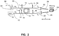
- FIG. 2 shows a dual frequency FMCW lidar in accordance with the present disclosure.
- the frequencies v 1 and v 2 of laser radiation vary linearly with time by current modulation of a laser 10, which may be a semiconductor laser.
- the radiation of frequency v 1m 14 from laser 10 is coupled to a narrow bandpass filter 18, which has a passband arranged to couple and pass v 1m 14 through the narrow bandpass filter 18 and into waveguide W 2 32.
- the narrow bandpass filter 18 may be an optical microresonator, a microring resonator, a plurality of mutually coupled ring resonators, or a plurality of coupling microresonators.
- the radiation of frequency v 2m 16 from laser 10 does not couple to the narrow bandpass filter 18 to waveguide W 2 32, instead v 2m 16 continues on waveguide W 1 12 to collimator C 1 22, and illuminates the object 26, whose velocity is to be measured.
- the radiation scattered from the object 26 moving with velocity ⁇ V along the direction of measurement is received at collimator C 2 3.0 and coupled to waveguide W 2 32.
- This provides a large displacement of the beat frequency by v 1 - v 2 from 0 Hz.
- the amount of the displacement from 0 Hz depends on the design of the laser cavity and allows measurement of the Doppler shift sign to provide an unambiguous measurement of the direction of the object velocity.
- An electronic or electro-optic modulator is not required, so much more accurate measurements can be obtained in comparison with the prior art.
- FIG. 3 shows the reference, transmitted, and received linearly chirped ramp waveforms.
- both transmitted beams from laser 10 with frequency v 1 40 and v 2 44 have the same modulation bandwidth B because both frequencies are the adjacent longitudinal modes of the same semiconductor laser 10 with a modulated current.
- FIG. 3 shows v 1m 14 varying between v 1 40 and v 1 + B 42.
- FIG. 3 also shows v 2m 16 varying between v 2 44 and v 2 + B 46, and shows the received waveform v 2m + f IF ⁇ f D 34.
- the displacement is a one sided frequency shift and allows directional measurement of object speed.
- the modulation bandwidth B is usually of order of a few gigahertz or less and the laser frequency may be typically about 2.10 14 Hz, or about 1.55 ⁇ m in wavelength. Therefore, the frequency separation between two adjacent longitudinal modes with ⁇ v L of about a few GHz may be changed by current modulation to tens of kHz or less, which is a negligible value.
- the single optical Microresonator 18, shown in FIG. 2 may have a rather narrow Lorentzian transmission shape. If a transmission linewidth of this filter is comparable with the modulation bandwidth B, this can result in the amplitude modulation of the beam v 1m 14 coupled to a narrow bandpass filter 18 and passed through this filter 18 into waveguide W 2 32. This modulation can develop sidebands and reduce the measurement accuracy. Therefore, it is necessary to use a broad enough transmission linewidth of the filter to exclude such a modulation. Also higher order filters, which are multiple mutually coupled ring resonators, may be used. Higher order filters have a much steeper roll-off and a flatter passband, as described in Reference [4] and [5], which are incorporated herein by reference. The use of such higher order filters is a preferred embodiment.
- the received scattered radiation v 2m ⁇ f D 34 can be coupled into a separate waveguide W 3 58, as shown in FIG. 4 , which is coupled directly to the photodetector (PD) 38.
- the scattered radiation v 2m ⁇ f D 34 does not ever pass through the narrow bandpass filter 18, which reduces any possible losses in the received signal, as compared to the embodiment of FIG. 2 in which the v 2m ⁇ f D 34 does pass through the narrow bandpass filter 18.
- FIG. 4 shows three coupled microresonators 50, 52 and 54, which may be used to improve the bandpass characteristics of the narrow bandpass filter 18 and to increase out-of-band signal rejection as described in References [4] and [5]
- the embodiment of FIG. 4 with v 2m + f IF ⁇ f D 34 coupled into a separate waveguide W 3 58, may use any narrow passband filter 18, such as the one described with reference to FIG. 2 .
- the radiation of frequency v 1m 14 from laser 10 is coupled to the three coupled microresonators 50, 52 and 54, which together have a passband arranged to couple and pass v 1m 14 through to waveguide W 2 56.
- the radiation of frequency v 2m 16 from laser 10 does not couple to the microresonators 50, 52 and 54 and instead v 2m 16 continues on waveguide W 1 . 12 to collimator C 1 22, and illuminates the object 26, whose velocity is to be measured.
- Waveguide W 2 56 and waveguide W 2 58 may be merged and then coupled to the photodetector 38 or separately coupled to the photodetector 38 by using a standard well-known technique of free space beam combining with beamsplitter.
- the beams when the beams are coupled to the photodetector in free space, the beams must be well collimated and absolutely parallel to each other for efficient development of beat frequency f IF .
- Any laser 10 with a cavity design which results in a desired longitudinal mode separation can be used.
- the progress in semiconductor lasers in the last decade has resulted in development of small-sized high power lasers which can be directly used in integrated optical circuits. Therefore, the application of semiconductor lasers in the proposed method is preferable.
- a laser 10 having only two frequencies For operation of the method, it is not necessary to use a laser 10 having only two frequencies.
- a laser 10 having more than two longitudinal modes can be used in the method.
- lasers having one powerful longitudinal mode and one or more weak longitudinal modes may be used. The most powerful longitudinal mode may be used for transmission to the object and any adjacent weak mode having 10 or even 100 times a lower intensity than the most powerful longitudinal mode may be used as a reference radiation.
- the laser 10 may be a laser diode, a quantum cascade laser, or an optical fiber laser.
- Such lasers can be developed by application of well-known techniques by proper design of periodic structures like distributed feedback Bragg (DFB) gratings over the active region of lasers or distributed Bragg reflectors (DBR) as one of the laser mirrors.
- DBR distributed feedback Bragg
- Another narrowband reflector which can be used as a mirror for spectral design of any laser is a volume Bragg grating (VBG).
Landscapes
- Physics & Mathematics (AREA)
- Engineering & Computer Science (AREA)
- Computer Networks & Wireless Communication (AREA)
- Electromagnetism (AREA)
- General Physics & Mathematics (AREA)
- Radar, Positioning & Navigation (AREA)
- Remote Sensing (AREA)
- Signal Processing (AREA)
- Spectroscopy & Molecular Physics (AREA)
- General Engineering & Computer Science (AREA)
- Optical Radar Systems And Details Thereof (AREA)
- Optics & Photonics (AREA)
- Condensed Matter Physics & Semiconductors (AREA)
Claims (9)
- Lidar-System, das folgendes umfasst:einen Laser (10) mit einer ersten frequenzmodulierten Laserstrahlung (14) und einer zweiten frequenzmodulierten Laserstrahlung (16);einen ersten Wellenleiter (12), der mit dem Laser (10) gekoppelt ist, wobei die erste frequenzmodulierte Laserstrahlung (14) und die zweite frequenzmodulierte Laserstrahlung (16) durch den Laser (10) in den ersten Wellenleiter (12) übermittelt werden;einen zweiten Wellenleiter (32; 56);einen Filter (18; 50, 52, 54), der zwischen den ersten Wellenleiter (12) und den zweiten Wellenleiter (32; 56) gekoppelt ist, wobei der Filter (18; 50, 52, 54) so gestaltet ist, dass er die erste frequenzmodulierte Laserstrahlung (14) durch den Filter (18; 50, 52, 54) zu dem zweiten Wellenleiter (32; 56) koppelt und leitet, und wobei er so gestaltet ist, dass er die zweite frequenzmodulierte Laserstrahlung (16) nicht durch den Filter (18; 50, 52, 54) zu dem zweiten Wellenleiter (32; 56) koppelt oder leitet; wobei die zweite frequenzmodulierte Laserstrahlung (16) an dem ersten Wellenleiter (12) fortfährt und zur Illumination eines Objekts (26) verwendet wird; undeinen Photodetektor (38), der mit dem zweiten Wellenleiter (32) gekoppelt ist;wobei:die erste frequenzmodulierte Laserstrahlung (14) eine lineare Chirp-Rampenmodulation v1m umfasst; und wobeidie zweite frequenzmodulierte Laserstrahlung (16) eine lineare Chirp-Rampenmodulation v2m umfasst; undwobei der zweite Wellenleiter (32; 56) so angeordnet ist, dass er eine Wellenform empfängt, die eine Streustrahlung von v2m von dem Objekt (26) umfasst, verschoben um eine Dopplerverschiebung fD, bewirkt durch eine Geschwindigkeit des Objekts (26), so dass die empfangene Wellenform v2m + fIF ± fD entspricht;wobei der Photodetektor (38) so angeordnet ist, dass er die lineare Chirp-Rampenmodulation v1m mit der empfangenen Wellenform v2m + fIF ± fD mischt, um eine Schwebungsfrequenz Δv + fIF ± fD zu erzeugen, mit Δv = v1m - v2m; undwobei folgendes gilt:
 wobei folgendes gilt: Δt = 2L/c,wobei folgendes gilt:L ist eine Entfernung zu dem Objekt;c ist eine Geschwindigkeit des Lichts;B ist eine Bandbreite oder ein Bereich der Frequenzmodulation; undT ist eine Periode des Frequenzhubs.
 - Lidar-System nach Anspruch 1, das ferner folgendes umfasst:einen ersten Kollimator (22), der mit dem ersten Wellenleiter (12) gekoppelt ist; undeinen zweiten Kollimator (30), der mit dem zweiten Wellenleiter (32) gekoppelt ist.
- Lidar-System nach Anspruch 1, wobei:
der Laser (10) mindestens zwei Längsmodi aufweist. - Lidar-System nach Anspruch 1:
wobei Δv = v1m - v2m gleich c/(2nLc) ist, wobei folgendes gilt: c ist eine Lichtgeschwindigkeit, n ist ein Brechungsindex eines Resonatormaterials des Lasers (10), und Lc ist eine Resonatorlänge des Lasers (10). - Lidar-System nach Anspruch 4:
wobei eine optische Länge des Resonators nLc größer ist als 5 mm, so dass Δv = v1m - v2m größer oder gleich 30 GHz ist. - Lidar-System nach Anspruch 1, das ferner folgendes umfasst:einen dritten Wellenleiter (58);wobei der Photodetektor (38) auch mit dem dritten Wellenleiter (38) gekoppelt ist.
- Lidar-System nach Anspruch 6, das ferner folgendes umfasst:
einen zweiten Kollimator (30), der mit dem dritten Wellenleiter (58) gekoppelt ist. - Verfahren zur frequenzmodulierten Dauerstricherkennung des Abstands und der Geschwindigkeit eines Objekts (26), wobei das Verfahren folgendes umfasst:Übermitteln einer ersten frequenzmodulierten Laserstrahlung (14) von einem Laser (10) und einer zweiten frequenzmodulierten Laserstrahlung (16) von dem Laser (10) durch einen ersten Wellenleiter (12);Umleiten der ersten frequenzmodulierten Laserstrahlung (14) durch einen Filter (18; 50, 52, 54) in einen zweiten Wellenleiter (32, 56);Entkoppeln der zweiten frequenzmodulierten Laserstrahlung von dem ersten Wellenleiter (12) zur Exposition eines Objekts (26);Koppeln einer empfangenen Wellenform von Streustrahlung von dem Objekt (26) in den zweiten Wellenleiter (32, 56); undMischen der empfangenen Streustrahlung mit der ersten frequenzmodulierten Laserstrahlung;wobei:die erste frequenzmodulierte Laserstrahlung eine lineare Chirp-Rampenmodulation v1m umfasst; und wobeidie zweite frequenzmodulierte Laserstrahlung eine lineare Chirp-Rampenmodulation v2m umfasst;wobei die Streustrahlung eine Streustrahlung von v2m von dem Objekt (26) umfasst, verschoben um eine Dopplerverschiebung fD, bewirkt durch eine Geschwindigkeit des Objekts (26), so dass die empfangene Wellenform v2m + fIF ± fD entspricht;wobei ein Photodetektor (38), der mit dem zweiten Wellenleiter (32) gekoppelt ist, die lineare Chirp-Rampenmodulation v1m mit der empfangenen Wellenform mischt, um eine Schwebungsfrequenz Δv + fIF ± fD zu erzeugen, mit Δv = v1m - v2m; undwobei folgendes gilt:
 wobei folgendes gilt: Δt = 2L/c,wobei folgendes gilt:L ist eine Entfernung zu dem Objekt;c ist eine Geschwindigkeit des Lichts;B ist eine Bandbreite oder ein Bereich der Frequenzmodulation; undT ist eine Periode des Frequenzhubs.
 - Verfahren nach Anspruch 8, das ferner folgendes umfasst:Spektralmessung einer Schwebungsfrequenz von der gemischten empfangenen Streustrahlung und der ersten frequenzmodulierten Laserstrahlung; undAbleitung von Abstand und Geschwindigkeit des Objekts.
Applications Claiming Priority (2)
| Application Number | Priority Date | Filing Date | Title |
|---|---|---|---|
| US201762450047P | 2017-01-24 | 2017-01-24 | |
| PCT/US2017/035320 WO2018140075A1 (en) | 2017-01-24 | 2017-05-31 | Dual frequency fmcw lidar and method |
Publications (3)
| Publication Number | Publication Date |
|---|---|
| EP3574337A1 EP3574337A1 (de) | 2019-12-04 |
| EP3574337A4 EP3574337A4 (de) | 2020-11-11 |
| EP3574337B1 true EP3574337B1 (de) | 2022-11-23 |
Family
ID=62906265
Family Applications (1)
| Application Number | Title | Priority Date | Filing Date |
|---|---|---|---|
| EP17893678.7A Active EP3574337B1 (de) | 2017-01-24 | 2017-05-31 | Doppelfrequenz-fmcw-lidar und verfahren |
Country Status (4)
| Country | Link |
|---|---|
| US (1) | US10670721B2 (de) |
| EP (1) | EP3574337B1 (de) |
| CN (1) | CN110268280B (de) |
| WO (1) | WO2018140075A1 (de) |
Families Citing this family (17)
| Publication number | Priority date | Publication date | Assignee | Title |
|---|---|---|---|---|
| US12399279B1 (en) | 2016-02-15 | 2025-08-26 | Red Creamery Llc | Enhanced hybrid LIDAR with high-speed scanning |
| US12399278B1 (en) | 2016-02-15 | 2025-08-26 | Red Creamery Llc | Hybrid LIDAR with optically enhanced scanned laser |
| US12123950B2 (en) | 2016-02-15 | 2024-10-22 | Red Creamery, LLC | Hybrid LADAR with co-planar scanning and imaging field-of-view |
| US11556000B1 (en) | 2019-08-22 | 2023-01-17 | Red Creamery Llc | Distally-actuated scanning mirror |
| US10310085B2 (en) * | 2017-07-07 | 2019-06-04 | Mezmeriz Inc. | Photonic integrated distance measuring pixel and method of distance measurement |
| JP7279056B2 (ja) * | 2017-11-03 | 2023-05-22 | アクロノス インコーポレイテッド | Lidar及びレーザ用測定手法 |
| KR102363751B1 (ko) | 2018-09-05 | 2022-02-15 | 블랙모어 센서스 앤드 애널리틱스, 엘엘씨 | 코히런트 lidar의 피치-캐치 스캐닝을 위한 방법 및 시스템 |
| CN109613562B (zh) * | 2018-12-13 | 2022-11-08 | 北京无线电测量研究所 | 测风激光雷达有效探测边界的识别方法及装置 |
| CN109870677B (zh) * | 2019-03-13 | 2023-02-24 | 西安工业大学 | 一种调频连续波干涉信号幅度归一化方法 |
| FR3096788B1 (fr) * | 2019-05-29 | 2021-06-11 | Thales Sa | Système lidar comprenant un élément diffractif interférentiel et procédé d'imagerie lidar |
| CN111208084A (zh) * | 2020-01-15 | 2020-05-29 | 大连理工大学 | 一种基于相干探测方法的光纤气体浓度遥感探测装置和方法 |
| DE102020104385A1 (de) | 2020-02-19 | 2021-08-19 | OSRAM Opto Semiconductors Gesellschaft mit beschränkter Haftung | Lasersystem und betriebsverfahren für ein lasersystem |
| CN111562564B (zh) * | 2020-05-25 | 2022-04-15 | 浙江光珀智能科技有限公司 | 一种调频连续波激光测距非线性校正装置及方法 |
| CN114325636B (zh) * | 2020-09-27 | 2024-12-17 | 北京万集科技股份有限公司 | 激光雷达芯片、激光雷达及其激光探测方法 |
| KR20220144700A (ko) * | 2021-04-20 | 2022-10-27 | 삼성전자주식회사 | 복수의 스위치를 포함하는 라이다 장치 |
| FR3127586B1 (fr) * | 2021-09-30 | 2023-09-29 | Commissariat Energie Atomique | système imageur lidar a detection heterodyne de type FMCW a resolution en distance amelioree |
| CN116908815B (zh) * | 2023-09-12 | 2023-12-29 | 深圳市速腾聚创科技有限公司 | 激光雷达及可移动设备 |
Family Cites Families (27)
| Publication number | Priority date | Publication date | Assignee | Title |
|---|---|---|---|---|
| DE2834954A1 (de) * | 1978-08-10 | 1980-02-21 | Honeywell Gmbh | Entfernungs- und geschwindigkeitsmesseinrichtung mit rauschfrequenzmoduliertem sender |
| US4812035A (en) * | 1986-11-03 | 1989-03-14 | Raytheon Company | AM-FM laser radar |
| US5534993A (en) * | 1994-06-15 | 1996-07-09 | United Technologies Corporation | Dual-wavelength frequency-chirped microwave AMCW ladar system |
| US5822047A (en) * | 1995-08-29 | 1998-10-13 | The United States Of America As Represented By The Secretary Of The Navy | Modulator LIDAR system |
| DE19631165A1 (de) * | 1996-08-01 | 1998-02-05 | Siemens Ag | Verfahren und Vorrichtung zur Elimination von Störeinflüssen beim FMCW-Radar |
| EP1454159A2 (de) | 2001-12-14 | 2004-09-08 | Raytheon Company | Ruckfahrhilfe-anzeigevorrichtung |
| US7106447B2 (en) | 2002-03-01 | 2006-09-12 | Michigan Aerospace Corporation | Molecular optical air data systems (MOADS) |
| US9134231B2 (en) * | 2003-06-04 | 2015-09-15 | Tomophase, Inc. | Optical measurements of properties in substances using propagation modes of light |
| CA2597712C (en) * | 2005-02-14 | 2013-08-13 | Digital Signal Corporation | Laser radar system and system and method for providing chirped electromagnetic radiation |
| US7139446B2 (en) * | 2005-02-17 | 2006-11-21 | Metris Usa Inc. | Compact fiber optic geometry for a counter-chirp FMCW coherent laser radar |
| US7742152B2 (en) * | 2006-06-23 | 2010-06-22 | University Of Kansas | Coherent detection scheme for FM chirped laser radar |
| US7974534B2 (en) | 2006-08-11 | 2011-07-05 | Purdue Research Foundation | Wideband microwave and millimeter wave filters using photonic spectral filtering |
| DE102007014256B4 (de) * | 2007-03-24 | 2013-08-08 | Mbda Deutschland Gmbh | Zielerfassungsverfahren und -Vorrichtung mit kohärentem Empfang |
| EP2128561B1 (de) * | 2008-05-28 | 2014-10-29 | Leica Geosystems AG | Interferometrisches Distanzmessverfahren mit verzögertem Chirp-Signal und ebensolche Vorrichtung |
| EP2128560B1 (de) * | 2008-05-28 | 2015-07-01 | Leica Geosystems AG | Interferometrisches Distanzmessverfahren mit spektral trennbarem Doppelchirp und ebensolche Vorrichtung |
| US8597577B2 (en) * | 2010-02-19 | 2013-12-03 | California Institute Of Technology | Swept-frequency semiconductor laser coupled to microfabricated biomolecular sensor and methods related thereto |
| WO2012103557A2 (en) * | 2011-01-28 | 2012-08-02 | The Regents Of The University Of Colorado, A Body Corporate | Spectral phase analysis for precision ranging |
| WO2013094431A1 (ja) * | 2011-12-21 | 2013-06-27 | 三菱電機株式会社 | レーザレーダ装置 |
| US8908160B2 (en) | 2011-12-23 | 2014-12-09 | Optical Air Data Systems, Llc | Optical air data system suite of sensors |
| US9007569B2 (en) * | 2012-08-03 | 2015-04-14 | The United States Of America As Represented By The Administrator Of The National Aeronautics And Space Administration | Coherent doppler lidar for measuring altitude, ground velocity, and air velocity of aircraft and spaceborne vehicles |
| JP5945214B2 (ja) * | 2012-11-13 | 2016-07-05 | 住友電工ハードメタル株式会社 | 光学部品 |
| US8988754B2 (en) * | 2013-01-08 | 2015-03-24 | Massachusetts Institute Of Technology | Optical phased arrays with evanescently-coupled antennas |
| US9335414B2 (en) * | 2014-07-11 | 2016-05-10 | Raytheon Company | Frequency agile LADAR |
| EP3032277B1 (de) * | 2014-12-12 | 2021-04-07 | Leica Geosystems AG | Lasertracker |
| CN107567592B (zh) * | 2015-04-07 | 2021-07-16 | 闪光股份有限公司 | 小型激光雷达系统 |
| CN204719233U (zh) * | 2015-06-18 | 2015-10-21 | 北京理工大学 | 一种基于双频激光的目标探测装置 |
| CN105589074A (zh) * | 2015-11-27 | 2016-05-18 | 中国人民解放军国防科学技术大学 | 基于飞秒光梳同步锁频的多波长干涉实时绝对测距装置 |
-
2017
- 2017-05-31 EP EP17893678.7A patent/EP3574337B1/de active Active
- 2017-05-31 US US15/609,788 patent/US10670721B2/en active Active
- 2017-05-31 CN CN201780081650.5A patent/CN110268280B/zh active Active
- 2017-05-31 WO PCT/US2017/035320 patent/WO2018140075A1/en not_active Ceased
Also Published As
| Publication number | Publication date |
|---|---|
| EP3574337A1 (de) | 2019-12-04 |
| US20180210068A1 (en) | 2018-07-26 |
| CN110268280B (zh) | 2023-08-08 |
| CN110268280A (zh) | 2019-09-20 |
| EP3574337A4 (de) | 2020-11-11 |
| WO2018140075A1 (en) | 2018-08-02 |
| US10670721B2 (en) | 2020-06-02 |
Similar Documents
| Publication | Publication Date | Title |
|---|---|---|
| EP3574337B1 (de) | Doppelfrequenz-fmcw-lidar und verfahren | |
| US11675078B2 (en) | LiDAR system | |
| US11442149B2 (en) | LiDAR system | |
| EP3627184B1 (de) | Laserradargerät und frequenzmodulationssteuerverfahren | |
| EP3973312B1 (de) | Frequenzmodulierter abtast-lidar mit 360-grad-sichtfeld | |
| JP6806347B2 (ja) | 光学的距離測定装置及び測定方法 | |
| US20190072672A1 (en) | Applications of optoelectronic oscillator (oeo) including light detection and ranging (lidar) and optical frequency domain reflectometer (ofdr) systems | |
| US8289523B2 (en) | Method and device for generating a synthetic wavelength | |
| US20190154835A1 (en) | Lidar system | |
| EP3973314B1 (de) | Scanning-lidar ohne bewegliche teile mit 360-grad-sichtfeld | |
| US8654342B2 (en) | Interferometric distance-measuring method with delayed chirp signal and such an apparatus | |
| US11098998B2 (en) | Apparatus and method for optical angle modulation measurement by a delayed self-heterodyne method | |
| EP3577424B1 (de) | Optische heterodyne detektion von luftdruck, temperatur und windgeschwindigkeit und verfahren | |
| US11906665B2 (en) | Method for scanning a transmitted beam through a 360° field-of-view (FOV) | |
| CN102047070A (zh) | 利用光谱可分离双啁啾的干涉距离测量方法及装置 | |
| CN114442110A (zh) | 一种调频连续波激光雷达 | |
| US6856723B1 (en) | Group velocity dispersion measuring device and group velocity dispersion measuring method | |
| Zhang et al. | Monolithic integrated linear frequency modulated dual-wavelength DFB laser chip with high linearity and its application in long distance ranging | |
| KR102821352B1 (ko) | 광-마이크로파 혼합 기반의 진폭 변조 레이저 거리 측정 장치 및 방법 | |
| JP7654246B2 (ja) | 距離、速度測定装置及び距離、速度測定方法 | |
| JP2002090259A (ja) | 半導体レーザ光源装置及び光周波数領域反射測定装置 | |
| Lukashchuk et al. | Microresonator dual-comb coherent FMCW LiDAR | |
| Kitora et al. | Simultaneous detection of distance and velocity via asymmetric carrier-suppressed double sideband modulation with a Kerr-microresonator soliton comb | |
| Hao et al. | Cost-Effective Frequency-Chirped Amplitude-Modulated Continuous-Wave LiDAR for Scalable High-Performance Ranging | |
| CN118209958A (zh) | 激光雷达设备 |
Legal Events
| Date | Code | Title | Description |
|---|---|---|---|
| STAA | Information on the status of an ep patent application or granted ep patent |
Free format text: STATUS: THE INTERNATIONAL PUBLICATION HAS BEEN MADE |
|
| PUAI | Public reference made under article 153(3) epc to a published international application that has entered the european phase |
Free format text: ORIGINAL CODE: 0009012 |
|
| STAA | Information on the status of an ep patent application or granted ep patent |
Free format text: STATUS: REQUEST FOR EXAMINATION WAS MADE |
|
| 17P | Request for examination filed |
Effective date: 20190724 |
|
| AK | Designated contracting states |
Kind code of ref document: A1 Designated state(s): AL AT BE BG CH CY CZ DE DK EE ES FI FR GB GR HR HU IE IS IT LI LT LU LV MC MK MT NL NO PL PT RO RS SE SI SK SM TR |
|
| AX | Request for extension of the european patent |
Extension state: BA ME |
|
| DAV | Request for validation of the european patent (deleted) | ||
| DAX | Request for extension of the european patent (deleted) | ||
| REG | Reference to a national code |
Ref country code: DE Ref legal event code: R079 Ref document number: 602017064026 Country of ref document: DE Free format text: PREVIOUS MAIN CLASS: G01S0007481000 Ipc: G01S0007491200 |
|
| A4 | Supplementary search report drawn up and despatched |
Effective date: 20201008 |
|
| RIC1 | Information provided on ipc code assigned before grant |
Ipc: H04L 27/10 20060101ALI20201002BHEP Ipc: G01S 17/58 20060101ALI20201002BHEP Ipc: G01S 17/34 20200101ALI20201002BHEP Ipc: G01S 7/481 20060101ALI20201002BHEP Ipc: G01S 7/4912 20200101AFI20201002BHEP Ipc: H04L 27/144 20060101ALI20201002BHEP Ipc: G01R 35/00 20060101ALI20201002BHEP Ipc: G01R 31/28 20060101ALI20201002BHEP |
|
| GRAP | Despatch of communication of intention to grant a patent |
Free format text: ORIGINAL CODE: EPIDOSNIGR1 |
|
| STAA | Information on the status of an ep patent application or granted ep patent |
Free format text: STATUS: GRANT OF PATENT IS INTENDED |
|
| INTG | Intention to grant announced |
Effective date: 20220624 |
|
| GRAS | Grant fee paid |
Free format text: ORIGINAL CODE: EPIDOSNIGR3 |
|
| GRAA | (expected) grant |
Free format text: ORIGINAL CODE: 0009210 |
|
| STAA | Information on the status of an ep patent application or granted ep patent |
Free format text: STATUS: THE PATENT HAS BEEN GRANTED |
|
| AK | Designated contracting states |
Kind code of ref document: B1 Designated state(s): AL AT BE BG CH CY CZ DE DK EE ES FI FR GB GR HR HU IE IS IT LI LT LU LV MC MK MT NL NO PL PT RO RS SE SI SK SM TR |
|
| REG | Reference to a national code |
Ref country code: GB Ref legal event code: FG4D |
|
| REG | Reference to a national code |
Ref country code: CH Ref legal event code: EP |
|
| REG | Reference to a national code |
Ref country code: AT Ref legal event code: REF Ref document number: 1533459 Country of ref document: AT Kind code of ref document: T Effective date: 20221215 Ref country code: DE Ref legal event code: R096 Ref document number: 602017064026 Country of ref document: DE |
|
| REG | Reference to a national code |
Ref country code: IE Ref legal event code: FG4D |
|
| REG | Reference to a national code |
Ref country code: LT Ref legal event code: MG9D |
|
| REG | Reference to a national code |
Ref country code: NL Ref legal event code: MP Effective date: 20221123 |
|
| REG | Reference to a national code |
Ref country code: AT Ref legal event code: MK05 Ref document number: 1533459 Country of ref document: AT Kind code of ref document: T Effective date: 20221123 |
|
| PG25 | Lapsed in a contracting state [announced via postgrant information from national office to epo] |
Ref country code: SE Free format text: LAPSE BECAUSE OF FAILURE TO SUBMIT A TRANSLATION OF THE DESCRIPTION OR TO PAY THE FEE WITHIN THE PRESCRIBED TIME-LIMIT Effective date: 20221123 Ref country code: PT Free format text: LAPSE BECAUSE OF FAILURE TO SUBMIT A TRANSLATION OF THE DESCRIPTION OR TO PAY THE FEE WITHIN THE PRESCRIBED TIME-LIMIT Effective date: 20230323 Ref country code: NO Free format text: LAPSE BECAUSE OF FAILURE TO SUBMIT A TRANSLATION OF THE DESCRIPTION OR TO PAY THE FEE WITHIN THE PRESCRIBED TIME-LIMIT Effective date: 20230223 Ref country code: LT Free format text: LAPSE BECAUSE OF FAILURE TO SUBMIT A TRANSLATION OF THE DESCRIPTION OR TO PAY THE FEE WITHIN THE PRESCRIBED TIME-LIMIT Effective date: 20221123 Ref country code: FI Free format text: LAPSE BECAUSE OF FAILURE TO SUBMIT A TRANSLATION OF THE DESCRIPTION OR TO PAY THE FEE WITHIN THE PRESCRIBED TIME-LIMIT Effective date: 20221123 Ref country code: ES Free format text: LAPSE BECAUSE OF FAILURE TO SUBMIT A TRANSLATION OF THE DESCRIPTION OR TO PAY THE FEE WITHIN THE PRESCRIBED TIME-LIMIT Effective date: 20221123 Ref country code: AT Free format text: LAPSE BECAUSE OF FAILURE TO SUBMIT A TRANSLATION OF THE DESCRIPTION OR TO PAY THE FEE WITHIN THE PRESCRIBED TIME-LIMIT Effective date: 20221123 |
|
| PG25 | Lapsed in a contracting state [announced via postgrant information from national office to epo] |
Ref country code: RS Free format text: LAPSE BECAUSE OF FAILURE TO SUBMIT A TRANSLATION OF THE DESCRIPTION OR TO PAY THE FEE WITHIN THE PRESCRIBED TIME-LIMIT Effective date: 20221123 Ref country code: PL Free format text: LAPSE BECAUSE OF FAILURE TO SUBMIT A TRANSLATION OF THE DESCRIPTION OR TO PAY THE FEE WITHIN THE PRESCRIBED TIME-LIMIT Effective date: 20221123 Ref country code: LV Free format text: LAPSE BECAUSE OF FAILURE TO SUBMIT A TRANSLATION OF THE DESCRIPTION OR TO PAY THE FEE WITHIN THE PRESCRIBED TIME-LIMIT Effective date: 20221123 Ref country code: IS Free format text: LAPSE BECAUSE OF FAILURE TO SUBMIT A TRANSLATION OF THE DESCRIPTION OR TO PAY THE FEE WITHIN THE PRESCRIBED TIME-LIMIT Effective date: 20230323 Ref country code: HR Free format text: LAPSE BECAUSE OF FAILURE TO SUBMIT A TRANSLATION OF THE DESCRIPTION OR TO PAY THE FEE WITHIN THE PRESCRIBED TIME-LIMIT Effective date: 20221123 Ref country code: GR Free format text: LAPSE BECAUSE OF FAILURE TO SUBMIT A TRANSLATION OF THE DESCRIPTION OR TO PAY THE FEE WITHIN THE PRESCRIBED TIME-LIMIT Effective date: 20230224 |
|
| P01 | Opt-out of the competence of the unified patent court (upc) registered |
Effective date: 20230523 |
|
| PG25 | Lapsed in a contracting state [announced via postgrant information from national office to epo] |
Ref country code: NL Free format text: LAPSE BECAUSE OF FAILURE TO SUBMIT A TRANSLATION OF THE DESCRIPTION OR TO PAY THE FEE WITHIN THE PRESCRIBED TIME-LIMIT Effective date: 20221123 |
|
| PG25 | Lapsed in a contracting state [announced via postgrant information from national office to epo] |
Ref country code: SM Free format text: LAPSE BECAUSE OF FAILURE TO SUBMIT A TRANSLATION OF THE DESCRIPTION OR TO PAY THE FEE WITHIN THE PRESCRIBED TIME-LIMIT Effective date: 20221123 Ref country code: RO Free format text: LAPSE BECAUSE OF FAILURE TO SUBMIT A TRANSLATION OF THE DESCRIPTION OR TO PAY THE FEE WITHIN THE PRESCRIBED TIME-LIMIT Effective date: 20221123 Ref country code: EE Free format text: LAPSE BECAUSE OF FAILURE TO SUBMIT A TRANSLATION OF THE DESCRIPTION OR TO PAY THE FEE WITHIN THE PRESCRIBED TIME-LIMIT Effective date: 20221123 Ref country code: DK Free format text: LAPSE BECAUSE OF FAILURE TO SUBMIT A TRANSLATION OF THE DESCRIPTION OR TO PAY THE FEE WITHIN THE PRESCRIBED TIME-LIMIT Effective date: 20221123 Ref country code: CZ Free format text: LAPSE BECAUSE OF FAILURE TO SUBMIT A TRANSLATION OF THE DESCRIPTION OR TO PAY THE FEE WITHIN THE PRESCRIBED TIME-LIMIT Effective date: 20221123 |
|
| REG | Reference to a national code |
Ref country code: DE Ref legal event code: R097 Ref document number: 602017064026 Country of ref document: DE |
|
| PG25 | Lapsed in a contracting state [announced via postgrant information from national office to epo] |
Ref country code: SK Free format text: LAPSE BECAUSE OF FAILURE TO SUBMIT A TRANSLATION OF THE DESCRIPTION OR TO PAY THE FEE WITHIN THE PRESCRIBED TIME-LIMIT Effective date: 20221123 Ref country code: AL Free format text: LAPSE BECAUSE OF FAILURE TO SUBMIT A TRANSLATION OF THE DESCRIPTION OR TO PAY THE FEE WITHIN THE PRESCRIBED TIME-LIMIT Effective date: 20221123 |
|
| PLBE | No opposition filed within time limit |
Free format text: ORIGINAL CODE: 0009261 |
|
| STAA | Information on the status of an ep patent application or granted ep patent |
Free format text: STATUS: NO OPPOSITION FILED WITHIN TIME LIMIT |
|
| 26N | No opposition filed |
Effective date: 20230824 |
|
| PG25 | Lapsed in a contracting state [announced via postgrant information from national office to epo] |
Ref country code: SI Free format text: LAPSE BECAUSE OF FAILURE TO SUBMIT A TRANSLATION OF THE DESCRIPTION OR TO PAY THE FEE WITHIN THE PRESCRIBED TIME-LIMIT Effective date: 20221123 |
|
| REG | Reference to a national code |
Ref country code: CH Ref legal event code: PL |
|
| PG25 | Lapsed in a contracting state [announced via postgrant information from national office to epo] |
Ref country code: MC Free format text: LAPSE BECAUSE OF FAILURE TO SUBMIT A TRANSLATION OF THE DESCRIPTION OR TO PAY THE FEE WITHIN THE PRESCRIBED TIME-LIMIT Effective date: 20221123 |
|
| GBPC | Gb: european patent ceased through non-payment of renewal fee |
Effective date: 20230531 |
|
| REG | Reference to a national code |
Ref country code: BE Ref legal event code: MM Effective date: 20230531 |
|
| PG25 | Lapsed in a contracting state [announced via postgrant information from national office to epo] |
Ref country code: MC Free format text: LAPSE BECAUSE OF FAILURE TO SUBMIT A TRANSLATION OF THE DESCRIPTION OR TO PAY THE FEE WITHIN THE PRESCRIBED TIME-LIMIT Effective date: 20221123 Ref country code: LU Free format text: LAPSE BECAUSE OF NON-PAYMENT OF DUE FEES Effective date: 20230531 Ref country code: LI Free format text: LAPSE BECAUSE OF NON-PAYMENT OF DUE FEES Effective date: 20230531 Ref country code: CH Free format text: LAPSE BECAUSE OF NON-PAYMENT OF DUE FEES Effective date: 20230531 |
|
| REG | Reference to a national code |
Ref country code: IE Ref legal event code: MM4A |
|
| PG25 | Lapsed in a contracting state [announced via postgrant information from national office to epo] |
Ref country code: IE Free format text: LAPSE BECAUSE OF NON-PAYMENT OF DUE FEES Effective date: 20230531 |
|
| PG25 | Lapsed in a contracting state [announced via postgrant information from national office to epo] |
Ref country code: IE Free format text: LAPSE BECAUSE OF NON-PAYMENT OF DUE FEES Effective date: 20230531 Ref country code: GB Free format text: LAPSE BECAUSE OF NON-PAYMENT OF DUE FEES Effective date: 20230531 |
|
| PG25 | Lapsed in a contracting state [announced via postgrant information from national office to epo] |
Ref country code: IT Free format text: LAPSE BECAUSE OF FAILURE TO SUBMIT A TRANSLATION OF THE DESCRIPTION OR TO PAY THE FEE WITHIN THE PRESCRIBED TIME-LIMIT Effective date: 20221123 Ref country code: FR Free format text: LAPSE BECAUSE OF NON-PAYMENT OF DUE FEES Effective date: 20230531 Ref country code: BE Free format text: LAPSE BECAUSE OF NON-PAYMENT OF DUE FEES Effective date: 20230531 |
|
| PG25 | Lapsed in a contracting state [announced via postgrant information from national office to epo] |
Ref country code: BG Free format text: LAPSE BECAUSE OF FAILURE TO SUBMIT A TRANSLATION OF THE DESCRIPTION OR TO PAY THE FEE WITHIN THE PRESCRIBED TIME-LIMIT Effective date: 20221123 |
|
| PG25 | Lapsed in a contracting state [announced via postgrant information from national office to epo] |
Ref country code: BG Free format text: LAPSE BECAUSE OF FAILURE TO SUBMIT A TRANSLATION OF THE DESCRIPTION OR TO PAY THE FEE WITHIN THE PRESCRIBED TIME-LIMIT Effective date: 20221123 |
|
| PGFP | Annual fee paid to national office [announced via postgrant information from national office to epo] |
Ref country code: DE Payment date: 20250529 Year of fee payment: 9 |
|
| PG25 | Lapsed in a contracting state [announced via postgrant information from national office to epo] |
Ref country code: CY Free format text: LAPSE BECAUSE OF FAILURE TO SUBMIT A TRANSLATION OF THE DESCRIPTION OR TO PAY THE FEE WITHIN THE PRESCRIBED TIME-LIMIT; INVALID AB INITIO Effective date: 20170531 |
|
| PG25 | Lapsed in a contracting state [announced via postgrant information from national office to epo] |
Ref country code: HU Free format text: LAPSE BECAUSE OF FAILURE TO SUBMIT A TRANSLATION OF THE DESCRIPTION OR TO PAY THE FEE WITHIN THE PRESCRIBED TIME-LIMIT; INVALID AB INITIO Effective date: 20170531 |
|
| PG25 | Lapsed in a contracting state [announced via postgrant information from national office to epo] |
Ref country code: TR Free format text: LAPSE BECAUSE OF FAILURE TO SUBMIT A TRANSLATION OF THE DESCRIPTION OR TO PAY THE FEE WITHIN THE PRESCRIBED TIME-LIMIT Effective date: 20221123 |