EP3574556B1 - System und verfahren für lasersystem mit nichtplanaren dünnscheibenverstärkungsmedien - Google Patents
System und verfahren für lasersystem mit nichtplanaren dünnscheibenverstärkungsmedien Download PDFInfo
- Publication number
- EP3574556B1 EP3574556B1 EP18744688.5A EP18744688A EP3574556B1 EP 3574556 B1 EP3574556 B1 EP 3574556B1 EP 18744688 A EP18744688 A EP 18744688A EP 3574556 B1 EP3574556 B1 EP 3574556B1
- Authority
- EP
- European Patent Office
- Prior art keywords
- gain media
- media disc
- ase
- disc
- flat
- Prior art date
- Legal status (The legal status is an assumption and is not a legal conclusion. Google has not performed a legal analysis and makes no representation as to the accuracy of the status listed.)
- Active
Links
Images





Classifications
-
- H—ELECTRICITY
- H01—ELECTRIC ELEMENTS
- H01S—DEVICES USING THE PROCESS OF LIGHT AMPLIFICATION BY STIMULATED EMISSION OF RADIATION [LASER] TO AMPLIFY OR GENERATE LIGHT; DEVICES USING STIMULATED EMISSION OF ELECTROMAGNETIC RADIATION IN WAVE RANGES OTHER THAN OPTICAL
- H01S3/00—Lasers, i.e. devices using stimulated emission of electromagnetic radiation in the infrared, visible or ultraviolet wave range
- H01S3/05—Construction or shape of optical resonators; Accommodation of active medium therein; Shape of active medium
- H01S3/06—Construction or shape of active medium
- H01S3/0602—Crystal lasers or glass lasers
- H01S3/0604—Crystal lasers or glass lasers in the form of a plate or disc
-
- H—ELECTRICITY
- H01—ELECTRIC ELEMENTS
- H01S—DEVICES USING THE PROCESS OF LIGHT AMPLIFICATION BY STIMULATED EMISSION OF RADIATION [LASER] TO AMPLIFY OR GENERATE LIGHT; DEVICES USING STIMULATED EMISSION OF ELECTROMAGNETIC RADIATION IN WAVE RANGES OTHER THAN OPTICAL
- H01S3/00—Lasers, i.e. devices using stimulated emission of electromagnetic radiation in the infrared, visible or ultraviolet wave range
- H01S3/02—Constructional details
- H01S3/04—Arrangements for thermal management
- H01S3/0405—Conductive cooling, e.g. by heat sinks or thermo-electric elements
-
- H—ELECTRICITY
- H01—ELECTRIC ELEMENTS
- H01S—DEVICES USING THE PROCESS OF LIGHT AMPLIFICATION BY STIMULATED EMISSION OF RADIATION [LASER] TO AMPLIFY OR GENERATE LIGHT; DEVICES USING STIMULATED EMISSION OF ELECTROMAGNETIC RADIATION IN WAVE RANGES OTHER THAN OPTICAL
- H01S3/00—Lasers, i.e. devices using stimulated emission of electromagnetic radiation in the infrared, visible or ultraviolet wave range
- H01S3/02—Constructional details
- H01S3/04—Arrangements for thermal management
- H01S3/042—Arrangements for thermal management for solid state lasers
-
- H—ELECTRICITY
- H01—ELECTRIC ELEMENTS
- H01S—DEVICES USING THE PROCESS OF LIGHT AMPLIFICATION BY STIMULATED EMISSION OF RADIATION [LASER] TO AMPLIFY OR GENERATE LIGHT; DEVICES USING STIMULATED EMISSION OF ELECTROMAGNETIC RADIATION IN WAVE RANGES OTHER THAN OPTICAL
- H01S3/00—Lasers, i.e. devices using stimulated emission of electromagnetic radiation in the infrared, visible or ultraviolet wave range
- H01S3/05—Construction or shape of optical resonators; Accommodation of active medium therein; Shape of active medium
- H01S3/06—Construction or shape of active medium
- H01S3/0602—Crystal lasers or glass lasers
- H01S3/0612—Non-homogeneous structure
-
- H—ELECTRICITY
- H01—ELECTRIC ELEMENTS
- H01S—DEVICES USING THE PROCESS OF LIGHT AMPLIFICATION BY STIMULATED EMISSION OF RADIATION [LASER] TO AMPLIFY OR GENERATE LIGHT; DEVICES USING STIMULATED EMISSION OF ELECTROMAGNETIC RADIATION IN WAVE RANGES OTHER THAN OPTICAL
- H01S3/00—Lasers, i.e. devices using stimulated emission of electromagnetic radiation in the infrared, visible or ultraviolet wave range
- H01S3/05—Construction or shape of optical resonators; Accommodation of active medium therein; Shape of active medium
- H01S3/06—Construction or shape of active medium
- H01S3/0619—Coatings, e.g. AR, HR, passivation layer
- H01S3/0621—Coatings on the end-faces, e.g. input/output surfaces of the laser light
-
- H—ELECTRICITY
- H01—ELECTRIC ELEMENTS
- H01S—DEVICES USING THE PROCESS OF LIGHT AMPLIFICATION BY STIMULATED EMISSION OF RADIATION [LASER] TO AMPLIFY OR GENERATE LIGHT; DEVICES USING STIMULATED EMISSION OF ELECTROMAGNETIC RADIATION IN WAVE RANGES OTHER THAN OPTICAL
- H01S3/00—Lasers, i.e. devices using stimulated emission of electromagnetic radiation in the infrared, visible or ultraviolet wave range
- H01S3/05—Construction or shape of optical resonators; Accommodation of active medium therein; Shape of active medium
- H01S3/08—Construction or shape of optical resonators or components thereof
- H01S3/08081—Unstable resonators
-
- H—ELECTRICITY
- H01—ELECTRIC ELEMENTS
- H01S—DEVICES USING THE PROCESS OF LIGHT AMPLIFICATION BY STIMULATED EMISSION OF RADIATION [LASER] TO AMPLIFY OR GENERATE LIGHT; DEVICES USING STIMULATED EMISSION OF ELECTROMAGNETIC RADIATION IN WAVE RANGES OTHER THAN OPTICAL
- H01S3/00—Lasers, i.e. devices using stimulated emission of electromagnetic radiation in the infrared, visible or ultraviolet wave range
- H01S3/05—Construction or shape of optical resonators; Accommodation of active medium therein; Shape of active medium
- H01S3/08—Construction or shape of optical resonators or components thereof
- H01S3/081—Construction or shape of optical resonators or components thereof comprising three or more reflectors
- H01S3/0813—Configuration of resonator
- H01S3/0816—Configuration of resonator having 4 reflectors, e.g. Z-shaped resonators
-
- H—ELECTRICITY
- H01—ELECTRIC ELEMENTS
- H01S—DEVICES USING THE PROCESS OF LIGHT AMPLIFICATION BY STIMULATED EMISSION OF RADIATION [LASER] TO AMPLIFY OR GENERATE LIGHT; DEVICES USING STIMULATED EMISSION OF ELECTROMAGNETIC RADIATION IN WAVE RANGES OTHER THAN OPTICAL
- H01S3/00—Lasers, i.e. devices using stimulated emission of electromagnetic radiation in the infrared, visible or ultraviolet wave range
- H01S3/05—Construction or shape of optical resonators; Accommodation of active medium therein; Shape of active medium
- H01S3/08—Construction or shape of optical resonators or components thereof
- H01S3/081—Construction or shape of optical resonators or components thereof comprising three or more reflectors
- H01S3/0813—Configuration of resonator
- H01S3/0817—Configuration of resonator having 5 reflectors, e.g. W-shaped resonators
-
- H—ELECTRICITY
- H01—ELECTRIC ELEMENTS
- H01S—DEVICES USING THE PROCESS OF LIGHT AMPLIFICATION BY STIMULATED EMISSION OF RADIATION [LASER] TO AMPLIFY OR GENERATE LIGHT; DEVICES USING STIMULATED EMISSION OF ELECTROMAGNETIC RADIATION IN WAVE RANGES OTHER THAN OPTICAL
- H01S3/00—Lasers, i.e. devices using stimulated emission of electromagnetic radiation in the infrared, visible or ultraviolet wave range
- H01S3/09—Processes or apparatus for excitation, e.g. pumping
- H01S3/091—Processes or apparatus for excitation, e.g. pumping using optical pumping
- H01S3/094—Processes or apparatus for excitation, e.g. pumping using optical pumping by coherent light
- H01S3/0941—Processes or apparatus for excitation, e.g. pumping using optical pumping by coherent light of a laser diode
-
- H—ELECTRICITY
- H01—ELECTRIC ELEMENTS
- H01S—DEVICES USING THE PROCESS OF LIGHT AMPLIFICATION BY STIMULATED EMISSION OF RADIATION [LASER] TO AMPLIFY OR GENERATE LIGHT; DEVICES USING STIMULATED EMISSION OF ELECTROMAGNETIC RADIATION IN WAVE RANGES OTHER THAN OPTICAL
- H01S2301/00—Functional characteristics
- H01S2301/02—ASE (amplified spontaneous emission), noise; Reduction thereof
-
- H—ELECTRICITY
- H01—ELECTRIC ELEMENTS
- H01S—DEVICES USING THE PROCESS OF LIGHT AMPLIFICATION BY STIMULATED EMISSION OF RADIATION [LASER] TO AMPLIFY OR GENERATE LIGHT; DEVICES USING STIMULATED EMISSION OF ELECTROMAGNETIC RADIATION IN WAVE RANGES OTHER THAN OPTICAL
- H01S3/00—Lasers, i.e. devices using stimulated emission of electromagnetic radiation in the infrared, visible or ultraviolet wave range
- H01S3/02—Constructional details
- H01S3/04—Arrangements for thermal management
- H01S3/0407—Liquid cooling, e.g. by water
-
- H—ELECTRICITY
- H01—ELECTRIC ELEMENTS
- H01S—DEVICES USING THE PROCESS OF LIGHT AMPLIFICATION BY STIMULATED EMISSION OF RADIATION [LASER] TO AMPLIFY OR GENERATE LIGHT; DEVICES USING STIMULATED EMISSION OF ELECTROMAGNETIC RADIATION IN WAVE RANGES OTHER THAN OPTICAL
- H01S3/00—Lasers, i.e. devices using stimulated emission of electromagnetic radiation in the infrared, visible or ultraviolet wave range
- H01S3/05—Construction or shape of optical resonators; Accommodation of active medium therein; Shape of active medium
- H01S3/06—Construction or shape of active medium
- H01S3/0602—Crystal lasers or glass lasers
- H01S3/0615—Shape of end-face
-
- H—ELECTRICITY
- H01—ELECTRIC ELEMENTS
- H01S—DEVICES USING THE PROCESS OF LIGHT AMPLIFICATION BY STIMULATED EMISSION OF RADIATION [LASER] TO AMPLIFY OR GENERATE LIGHT; DEVICES USING STIMULATED EMISSION OF ELECTROMAGNETIC RADIATION IN WAVE RANGES OTHER THAN OPTICAL
- H01S3/00—Lasers, i.e. devices using stimulated emission of electromagnetic radiation in the infrared, visible or ultraviolet wave range
- H01S3/05—Construction or shape of optical resonators; Accommodation of active medium therein; Shape of active medium
- H01S3/06—Construction or shape of active medium
- H01S3/0619—Coatings, e.g. AR, HR, passivation layer
- H01S3/0621—Coatings on the end-faces, e.g. input/output surfaces of the laser light
- H01S3/0623—Antireflective [AR]
-
- H—ELECTRICITY
- H01—ELECTRIC ELEMENTS
- H01S—DEVICES USING THE PROCESS OF LIGHT AMPLIFICATION BY STIMULATED EMISSION OF RADIATION [LASER] TO AMPLIFY OR GENERATE LIGHT; DEVICES USING STIMULATED EMISSION OF ELECTROMAGNETIC RADIATION IN WAVE RANGES OTHER THAN OPTICAL
- H01S3/00—Lasers, i.e. devices using stimulated emission of electromagnetic radiation in the infrared, visible or ultraviolet wave range
- H01S3/05—Construction or shape of optical resonators; Accommodation of active medium therein; Shape of active medium
- H01S3/06—Construction or shape of active medium
- H01S3/07—Construction or shape of active medium consisting of a plurality of parts, e.g. segments
-
- H—ELECTRICITY
- H01—ELECTRIC ELEMENTS
- H01S—DEVICES USING THE PROCESS OF LIGHT AMPLIFICATION BY STIMULATED EMISSION OF RADIATION [LASER] TO AMPLIFY OR GENERATE LIGHT; DEVICES USING STIMULATED EMISSION OF ELECTROMAGNETIC RADIATION IN WAVE RANGES OTHER THAN OPTICAL
- H01S3/00—Lasers, i.e. devices using stimulated emission of electromagnetic radiation in the infrared, visible or ultraviolet wave range
- H01S3/09—Processes or apparatus for excitation, e.g. pumping
- H01S3/091—Processes or apparatus for excitation, e.g. pumping using optical pumping
- H01S3/094—Processes or apparatus for excitation, e.g. pumping using optical pumping by coherent light
- H01S3/09408—Pump redundancy
-
- H—ELECTRICITY
- H01—ELECTRIC ELEMENTS
- H01S—DEVICES USING THE PROCESS OF LIGHT AMPLIFICATION BY STIMULATED EMISSION OF RADIATION [LASER] TO AMPLIFY OR GENERATE LIGHT; DEVICES USING STIMULATED EMISSION OF ELECTROMAGNETIC RADIATION IN WAVE RANGES OTHER THAN OPTICAL
- H01S3/00—Lasers, i.e. devices using stimulated emission of electromagnetic radiation in the infrared, visible or ultraviolet wave range
- H01S3/09—Processes or apparatus for excitation, e.g. pumping
- H01S3/091—Processes or apparatus for excitation, e.g. pumping using optical pumping
- H01S3/094—Processes or apparatus for excitation, e.g. pumping using optical pumping by coherent light
- H01S3/094084—Processes or apparatus for excitation, e.g. pumping using optical pumping by coherent light with pump light recycling, i.e. with reinjection of the unused pump light, e.g. by reflectors or circulators
-
- H—ELECTRICITY
- H01—ELECTRIC ELEMENTS
- H01S—DEVICES USING THE PROCESS OF LIGHT AMPLIFICATION BY STIMULATED EMISSION OF RADIATION [LASER] TO AMPLIFY OR GENERATE LIGHT; DEVICES USING STIMULATED EMISSION OF ELECTROMAGNETIC RADIATION IN WAVE RANGES OTHER THAN OPTICAL
- H01S3/00—Lasers, i.e. devices using stimulated emission of electromagnetic radiation in the infrared, visible or ultraviolet wave range
- H01S3/09—Processes or apparatus for excitation, e.g. pumping
- H01S3/091—Processes or apparatus for excitation, e.g. pumping using optical pumping
- H01S3/094—Processes or apparatus for excitation, e.g. pumping using optical pumping by coherent light
- H01S3/0941—Processes or apparatus for excitation, e.g. pumping using optical pumping by coherent light of a laser diode
- H01S3/09415—Processes or apparatus for excitation, e.g. pumping using optical pumping by coherent light of a laser diode the pumping beam being parallel to the lasing mode of the pumped medium, e.g. end-pumping
-
- H—ELECTRICITY
- H01—ELECTRIC ELEMENTS
- H01S—DEVICES USING THE PROCESS OF LIGHT AMPLIFICATION BY STIMULATED EMISSION OF RADIATION [LASER] TO AMPLIFY OR GENERATE LIGHT; DEVICES USING STIMULATED EMISSION OF ELECTROMAGNETIC RADIATION IN WAVE RANGES OTHER THAN OPTICAL
- H01S3/00—Lasers, i.e. devices using stimulated emission of electromagnetic radiation in the infrared, visible or ultraviolet wave range
- H01S3/14—Lasers, i.e. devices using stimulated emission of electromagnetic radiation in the infrared, visible or ultraviolet wave range characterised by the material used as the active medium
- H01S3/16—Solid materials
- H01S3/1601—Solid materials characterised by an active (lasing) ion
- H01S3/1603—Solid materials characterised by an active (lasing) ion rare earth
-
- H—ELECTRICITY
- H01—ELECTRIC ELEMENTS
- H01S—DEVICES USING THE PROCESS OF LIGHT AMPLIFICATION BY STIMULATED EMISSION OF RADIATION [LASER] TO AMPLIFY OR GENERATE LIGHT; DEVICES USING STIMULATED EMISSION OF ELECTROMAGNETIC RADIATION IN WAVE RANGES OTHER THAN OPTICAL
- H01S3/00—Lasers, i.e. devices using stimulated emission of electromagnetic radiation in the infrared, visible or ultraviolet wave range
- H01S3/23—Arrangements of two or more lasers not provided for in groups H01S3/02 - H01S3/22, e.g. tandem arrangements of separate active media
- H01S3/2308—Amplifier arrangements, e.g. MOPA
Definitions
- the present application relates to a laser system and method having a disc-like gain media formed with a non-flat shape, and more specifically, it relates to a means for reducing the generation of amplified spontaneous emission enabling scaling of the transverse modal area to scale the average output power.
- Thin disk lasers make use of a thin disc gain media which forms part of the lasing cavity.
- the thin disc gain media is typically provided with a planar (i.e., flat) shape.
- This shape while being generally effective for the purpose of enabling the laser system to produce a uniform output beam with minimum distortions due to thermal gradients, does have certain limitations.
- One such limitation is the susceptibility of the flat thin disc media to transverse amplified spontaneous emission ("ASE"). Transverse ASE limits the spot size of the output laser beam that can be produced using the flat thin disc gain media, which in turn limits the power that can be delivered by the output laser beam.
- ASE transverse amplified spontaneous emission
- Another limitation is the susceptibility of the flat thin active disks to thermal induced lens effects which can also limit laser performance.
- an anti-ASE cap (undoped index matched layer) is typically utilized to mitigate the effects of ASE thus enabling power scaling via modal enlargement.
- This approach works up to a point, but eventually deleterious effects of ASE limit further scaling. Accordingly, there exists a need for further improvements in the laser art for laser systems that are capable of producing beams with even larger spot sizes than previously developed laser systems. Utilization of a non-flat (curved) disk enables further power scaling over that supported by flat thin disk laser architectures.
- the system comprises a non-flat gain media disc and a pump source configured to generate a beam that pumps the non-flat gain media disc.
- a laser cavity is formed by an optical component, the non-flat gain media disc and an output coupler enabling the laser beam to exit the laser cavity.
- a radius of curvature of the non-flat gain media is selected to reduce the amplified spontaneous emission.
- the present disclosure relates to a laser system disclosed in claim 1.
- the laser system may comprise a first pump source configured to generate a first beam, a second pump source configured to generate a second beam, a first mirror for receiving the first beam, and a second mirror for receiving the second beam.
- the laser system may also comprise a non-flat, thin disc gain media optical component for receiving the first and second beams reflected from the first and second mirrors thus exciting the non-flat gain media disc.
- An output coupler may be included for forming a resonant laser cavity .
- a highly reflective coating may be applied to a surface of the hemispherical shaped thin disc gain media, constituting an active mirror.
- the optical component may also include a cap layer consisting of a media refractive index and coefficient of thermal expansion matched to the gain media.
- the cap layer may also include an anti-reflective coating or other wavelength dependent coating.
- a method for forming a laser oscillator system may comprise using at least one pump source configured to generate a pump beam incident upon the non flat gain mirror.
- the method may further comprise using a laser cavity formed by the non-flat gain mirror and at least one additional optical component forming a resonant cavity.
- the resonate cavity may include one or more non-flat gain mirrors.
- the method may further comprise using an output coupler to receive and direct the output beam toward an external component.
- the present disclosure relates to a method of forming a laser amplifier system according to claim 14.
- the present invention utilizes a gain and index tailored multi-layered (composite) non-flat (curved) disk to further reduce the deleterious effects of ASE by reducing the spontaneous emission interaction length within the gain media. This allows the laser to be substantially scaled in power output beyond what is achievable utilizing conventional disk laser architectures.
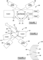
- FIG. 1 there is shown one example of a solid-state laser apparatus 10 in accordance with the present disclosure.
- the apparatus 10 in this example makes use of hemi-spherical thin disc gain media 12 that is illuminated by a pair of pump sources, shown in this example as diode pump lasers 14 and 16.
- An output coupler 18, along with the thin disc gain media 12, forms the lasing cavity.
- a coolant 20 may be supplied to the thin disc gain media 12 to cool the thin disc gain media.
- the curved thin disc gain media 12 is shown in high level form in Figure 2 and may include a substrate portion 22 having an outer surface 24, an inner surface 26, a gain media 28, and a high reflection ("HR") coating 30 covering the gain media coating 28.
- the diode pump lasers 14 and 16 provide pump laser beams 14a and 16a that illuminate a spot through the outer surface 24 of the thin disc gain media 12 at a vertex 31 of the thin disc gain media creating an excited state capable of providing optical gain.
- a resonant laser cavity is formed between the excited laser gain media 28 at the vertex 31 and the output coupler 18 forming a laser beam that may exit the device via the output coupler 18 port.
- the substrate portion 22 and the gain media 28 are index of refraction and coefficient of thermal expansion matched to reduce reflection and stress between the layers.
- the curved configuration of the thin disc gain media 12 helps to reduce transverse ASE and may enable even larger spot sizes to be generated with any given laser system.
- the curved configuration of the thin disc gain media 12 may also enable better mode selection, and may also be intrinsically stronger and more robust, and thus be more resistant to thermal induced deformations.
- FIG. 3 shows a laser system 50 in accordance with another embodiment of the present disclosure.
- a hemi-spherical thin disc gain media 52 receives energy via a pump beam 54a from a first pump source, which in this example is shown as diode pump laser 54, and lasing beam 56a from a second pump source, which is shown as diode pump laser 56.
- the lasing beams 54a and 56a excite the thin disc gain media 52.
- An output beam 58 is formed in the resonant laser cavity comprising the excited thin disc gain media region, the HR coating 72 and the output coupler 60.
- Optical energy in the form of an output beam exits the cavity through the output coupler 60.
- a coolant 62 may be supplied to the thin disc gain media 52 to cool it.
- the thin disc gain media 52 in this example has a substrate 64 with an inner surface 66 and an outer surface 68.
- a coating 70 comprising a gain media is placed on the inner surface 66 while an HR coating 72 is placed on the outer surface 68.
- this configuration i.e. direction of curvature of the disc relative to the geometry of the laser resonator
- this configuration may have other advantages, such as improved optical alignment for some specific laser configurations.
- the example is included in the range of examples of non-flat thin disc geometries but may not be the optimal choice of curvature for power and energy scaling.
- a solid-state laser apparatus 100 is shown in accordance with the embodiment of Figure 1 .
- the apparatus 100 comprises a non-flat active mirror 101 and an output coupling mirror 102 forming a laser resonator.
- the active hemispherical mirror 101 is optically pumped by an external pump source (103).
- the active hemispherical mirror 101 absorbs the pump energy and re-emits radiation into the laser resonator.
- the pump beam which is reflected by the active hemispherical mirror 101 is redirected back to the active hemispherical mirror by reflectors 104 to increase the pump absorption efficiency.
- a solid-state laser apparatus 600 which consists of two optical mirrors 601,602 separated by a distance, thus forming an optical resonator (e.g., stable, unstable, linear, ring, etc.).
- the mirror 601 comprises a non-flat active mirror and may consist of a plurality of layers including at least one optically active layer, optical coating layers and an anti-ASE layer.
- the layers are as specified in Figure 6 , with an outside high reflective coating 605, an optically active layer 606 capable of providing optical gain, an anti-ASE cap layer 607 and an anti-reflection coating 608.
- Other configurations of the layers and number of layers are possible.
- the three dimensional shape of the non-flat optical mirror 601 containing the optically active media 601 may be in the form of a hemisphere or other three dimensional curved shape, for example an ellipse, a parabola, etc., applicable to a specific resonator design which may include ether a concave (-R) or convex (+R) orientation of the active mirror 601.
- active mirrors with a +R or convex curvature are beneficial towards mitigating the detrimental effects of ASE, whereas concave mirrors (-R) may not be beneficial for ASE mitigation but may be beneficial towards other resonator configurations (i.e., stable geometrics not supported by a convex active mirror) and/ or parametric sensitivities, for example mirror misalignments, or thermal variations or other factors.
- Figure 7 shows a laser system 200 representing an unstable laser architecture formed by two three-dimensional active mirrors 202 and 204.
- the three dimensional active mirrors 202 and 204 are each formed with a hemispherical shape, and each operates as both a mirror and as a gain media.
- FIG 8 shows a laser system 300 which forms a multi-active mirror linear optical resonator laser consisting of two three-dimensional active mirror elements 302 and 304. Coolant 312 and 314 may be supplied to both of the active mirror elements 302 and 304. Again, each one of the active mirror elements 302 and 304 operate as both a mirror and a gain media. Element 306 forms the output coupler of the laser resonator in this configuration.
- the solid-state matrix used to make the three-dimensional active mirrors 202, 204, 302, 304 or the thin disc gain media 12, 52 or 106 may each comprise a homogeneous gain loaded matrix or a multi-layer matrix consisting of distinct layers of varying Rare Earth dopant concentrations and refractive indices.
- the Rare Earth dopants may include, but are not limited to, one or more of Erbium (Er), Ytterbium (Yb), Neodymium (Nd);Thulium (Tm); Praseodymium (Pr);Cerium (Ce);Holmium (Ho);Yttrium (Y); Samarium (Sm); Europium (Eu);Gadolinium (Gd);Terbium (Tb);Dysprosium (Dy); and Lutetium (Lu). Transition metals such as Chromium (Cr) and Titanium (Ti) may also be incorporated.
- Figure 9 shows one example of a three dimensional active mirror 400 having HR/AR coatings 402 and 404 on its inside or outside surfaces, the optical coatings by be uniform or tailored for resonator performance, and three distinct layers 406-410 of gain loaded matrix consisting of at least one optically active layer and at least one index match anti-ASE cap layer. It will be appreciated that a greater or lesser number of the matrix layers may be incorporated, and the use of three matrix layers 406-410 shown in Figure 9 is therefore merely one example of how the gain loaded matrix may be implemented.
- the dopant concentration may be tailored to reduce ASE and to tailor gain and modal confinement, while the thickness of the layers 406-410 and refractive index may be tailored for modal constituency, thermal dissipation, pump efficiency, structural rigidity, and other design or operational considerations.
- a stability diagram 500 is shown to illustrate various beam patterns that may be produced for a laser resonator consisting of two spherical mirrors of radius R1 and R2 separated by a distance L.
- the present invention relating to non-flat active mirrors of radius R1 when coupled to a second mirror of radius R2, is applicable to both stable and unstable laser resonator architectures featuring single or dual active mirrors.
- Mirror configurations falling within the shaded region of Figure 10 pertain to stable laser resonator architectures. Those outside this region are considered unstable.
- FIG. 11 a comparison between a well-known flat gain media disc 600 ( Figure 11 ) and a curved gain media disc 602 in accordance with one embodiment of the present disclosure is shown.
- the ASE multiplier is the factor by which the power of a spontaneous emitted photon is amplified by the gain region of the non-flat disc, such as disc 800 in Figure 14 or disc 900 in Figure 15 .
- the MASE is calculated by launching a number of rays from random locations and in random directions and adding up the total power emerging from the gain media where upon each pass of a ray through the gain media the ASE power is increased by e gL .
- a local MASE can also be calculated by finding the total net power leaving some subregion of the gain media. Spatial gain variations can be incorporated if needed.
- FIG 13 shows a graph 700 which illustrates how the MASE for a flat disc (line 702) which is shown as a constant line in the plot for the purpose of providing a simple comparison to the non-flat case.
- the MASE is a function of the radius of curvature of the disc 704.
- Graph 700 further illustrates (portion 704a) that an optimal non-flat gain media radius maximizes this reduction; further increase in bend radius reduces the effect (portion 704b).
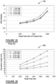
- Figure 16 shows a graph 1000 of the ASE multiplier vs. anti ASE cap thickness (in millimeters) for a flat gain media disc and a curved gain media disc of optimal radius of curvature, where for a given ASE cap thickness an optimal radius has been calculated and plotted as green triangles whose values may be determined by comparison with the right hand vertical axis.
- Figure 16 also illustrates that increasing the ASE cap thickness for a curved gain media disc continues to minimizing the ASE multiplier (red squares whose value can be determined from the left hand vertical axis), whereas in the flat case the benefit of the ASE cap is not increasing with increasing ASE cap thickness (blue diamonds whose value can be determined from the left hand vertical axis).
- the graph 1000 illustrates how a thicker cap for a curved given gain media disc can be used to significantly reduce the ASE compared to a flat disk with thicker anti-ASE cap.
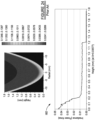
- Figures 17 and 18 show graphical distributions for the power distribution over an area of a conventional flat gain media disc 1100, as shown in Figure 17 , versus a curved gain media disc 1200 shown in Figure 18 .
- Figure 18 shows that the ASE is uniform over about 70%-80% of the surface of the curved gain media disc 1200 when the gain media disc 1200 has an optimal radius of 79.1mm and cap thickness of 1mm The uniformity of the ASE intensity for the curved disk is improved by a factor of 3-4 over that of the flat disk with comparable geometry.
- Figure 19 shows a graph 1300 illustrating that for a given curved gain media disc, the . ASE can be further reduced by reducing the radius of the disk for a given anti-ASE cap, constrained by the limits discussed above with regards to figures 13 and 16 .
- Figure 20 shows a pair of graphs 1400 and 1402 to illustrate how the curvature (both negative and positive) of a curved gain media disc may influence the MASE.
- Curve 1400 represents the ASE multiplier for a cap of a curved gain media disc having a 1mm thickness
- curve 1402 represents the ASE multiplier for a cap of a curved gain media disc having a 4mm thickness.
- Figure 20 shows the benefit of the configuration only occurs for thin disc radius of curvatures greater than zero, where positive and negative curvature are as defined above.
- Figure 21 illustrates a prior art flat gain media disc 1500 and a path length 1500a of one ray through the disc
- Figure 22 illustrates a curved gain media disc 1502 with a path length of one ray 1502a through the disc.
- the path ASE multiplier is significantly greater for the curved gain media disc 1502.
- Figure 23 illustrates a graph 1600 of a distribution of the ASE of a conventional flat gain media disc, relative to height
- Figure 24 illustrates a graph 1602 of the distribution of the ASE multiplier, relative to height, of a concave gain media disc.
- Figure 25 shows a graph 1700 that illustrates a plurality of curves showing examples of the single-pass gain for the pumped area of a conventional flat gain media disc, for pumped areas of different diameters.
- Figures 26 and 27 show graphs 1800 and 1900, respectively, which illustrate examples of how a curved gain media disc allows for a larger pumped area.
- a curved disc 2000 is shown in Figure 28 in accordance with another embodiment of the present disclosure.
- the curved disc 2000 in this example includes an index and gain tailored multi-layer composite active mirror containing a substrate portion 2002 and a layer forming a gain tailored portion 2004.
- the layer forming a gain tailored portion, i.e., gain tailored portion 2004, may be formed collectively by portions 2004a and 2004b.
- three or more distinct portions may be provided.
- Optical coatings may also be used on interior 2005 and exterior 2001 surfaces, respectively.
- One or more of the portions 2004a and 2004b may contain an active media defined within a central portion of the curved shell that forms the curved disc 2000.
- the composite mirror layers 2002, 2004a and 2004b form layers which may be matched with respect to coefficient of thermal expansion and index of refraction to minimize optical reflections between layers and to mitigate stress related thermal effects.
- Restricting the active media i.e., the layers of media capable of optical amplification actuated by optical pumping
- mode tailoring by offsetting the confinement factors of higher order modes to favor fundamental mode (or a sub-set of modes) operation for power scaling.
- a curved active disk mirror 2900 is illustrated in Figure 29 which is configured to operate as a laser amplifier.
- pump radiation is reflected back to the active curved disk 2903 via a series of reflectors 2902 redirecting the portion of pump radiation reflected by the curved disk (reflected pump beams), thereby increasing the pump absorption efficiency of the curved disk.
- the pump beams are absorbed by the active pump disc 2903 (i.e., the active element) and re-emitted via stimulated emission to amplify the incident laser radiation forming an output laser beam 2904 of higher optical power.
Landscapes
- Physics & Mathematics (AREA)
- Electromagnetism (AREA)
- Engineering & Computer Science (AREA)
- Plasma & Fusion (AREA)
- Optics & Photonics (AREA)
- Chemical & Material Sciences (AREA)
- Crystallography & Structural Chemistry (AREA)
- Lasers (AREA)
Claims (14)
- Lasersystem, das aufweist:eine nicht flache Scheibe als Verstärkungsmedium mit einem Verstärkungsbereich und einer Anti-ASE-Deckschicht, die konfiguriert ist, um die querverlaufende ASE zu reduzieren;mindestens eine Pumpquelle, die konfiguriert ist, um einen Strahl zu erzeugen, der die nicht flache Verstärkungsmediumscheibe bepumpt; undeinen Laserhohlraum, der aus mindestens einer optischen Komponente, der nicht flachen Scheibe, als Verstärkungsmedium gebildet ist; undeinen Ausgangskoppler, der den Laserstrahl ermöglicht, den Laserhohlraum zu verlassen,wobei die nicht flache Verstärkungsmediumscheibe eine halbkugelförmig gekrümmte, schalenförmige Scheibe als Verstärkungsmedium aufweist; und wobei der Krümmungsradius R des Verstärkungsbereichs ermittelt wird, durch:
 L = der Durchmesser einer flachen Scheibe mit gleichem Verstärkungsmedium, die den Verstärkungsbereich und die Anti-ASE-Deckschicht des Durchmessers L aufweist, undtc = die Dicke der Anti-ASE-Deckschicht.
 - Lasersystem nach Anspruch 1, das ferner einen Spiegel zum Empfangen und Reflektieren des Strahls von der Pumpquelle aufweist, wecher durch die mindestens eine, optische Komponente zurück zu der mindestens einen optischen Komponente reflektiert wird.
- Lasersystem des Anspruchs 1, wobei die mindestens eine optische Komponente ein Substrat aufweist, das an einer Oberfläche der halbkugelförmig gestalteten Verstärkungsmediumscheibe festgemacht ist.
- Lasersystem des Anspruchs 3, wobei die mindestens eine optische Komponente zusätzlich eine hochreflektierende Beschichtung auf einer Oberfläche des Substrats aufweist, die der gegenüberliegt, auf welcher die halbkugelförmig gestaltete Verstärkungsmediumscheibe festgemacht ist.
- Lasersystem des Anspruchs 1, das außerdem aufweist:eine zusätzliche Pumpquelle zur Erzeugung eines zusätzlichen Strahls; undeinen Spiegel zum Reflektieren des zusätzlichen Strahls in Richtung zu der mindestens einen, optischen Komponente.
- Lasersystem des Anspruchs 1, wobei die nicht flache Verstärkungsmediumscheibe ein Matrixmaterial im festen Zustand aufweist.
- Lasersystem des Anspruchs 6, wobei das Matrixmaterial im festen Zustand mindestens eine Art von seltenen Erden-Dotierstoff oder mindestens eine Art von Übergangsmetall oder eine Kombination aus mindestens einer Art von seltenen Erden-Dotierstoff und mindestens einer Art von Übergangsmetall aus den Folgenden enthält : Erbium (Er), Ytterbium (Yb), Neodym (Nd), Thulium (Tm), Praseodym (Pr), Cer (Ce), Holmium (Ho), Yttrium (Y), Samarium (Sm), Europium (Eu), Gadolinium (Gd), Terbium (Tb), Dysprosium (Dy), Lutetium (Lu), Chrom (Cr) und Titan (Ti).
- Lasersystem des Anspruchs 1, wobei die halbkugelförmig gekrümmte, schalenförmige Verstärkungsmediumscheibe mehrere Schichten von Verstärkungs angereicherten Matrixmaterial aufweist, die übereinandergeschichtet sind.
- Lasersystem des Anspruchs 8, das ferner eine erste hochreflektierende Beschichtung aufweist, die auf einer ersten Außenfläche der halbkugelförmig gekrümmten, schalenförmigen Verstärkungsmediumscheibe aufgebracht ist.
- Lasersystem des Anspruchs 9, das ferner eine anti-reflektierende Beschichtung aufweist, die auf einer zweiten Außenfläche der halbkugelförmig gekrümmten, schalenförmigen Verstärkungsmediumscheibe aufgebracht ist.
- Lasersystem des Anspruchs 1, wobei die mindestens eine optische Komponente einen aktiven Spiegel bildet.
- Lasersystem des Anspruchs 1, das ferner eine Wärmesenke aufweist, die mit der mindestens einen, optischen Komponente gekoppelt ist.
- Lasersystem des Anspruchs 1, das ferner ein Kühlmittel aufweist, das der mindestens einen, optischen Komponentezum Kühlen der mindestens einen, optischen Komponente zugeführt wird.
- Verfahren zum Bilden eines Laserverstärkersystems, das aufweist:das Verwenden mindestens einer Pumpquelle, die konfiguriert ist, um einen Strahl zu erzeugen, der auf eine nicht flache Scheibe als Verstärkungsmedium mit einem Verstärkungsbereich und einer Anti-ASE-Deckschicht trifft, die konfiguriert ist, um die querverlaufende ASE zu reduzieren; unddas Verwenden mindestens eines Extraktionsstrahls oder Signalstrahls, der mit der nicht flachen Verstärkungsmediumscheibe interagiert, indem er einmal oder mehrmals von der nicht flachen Verstärkungsmediumscheibe abprallt und dadurch mit jedem Durchgang Energie gewinnt,wobei die nicht flache Verstärkungsmediumscheibe eine halbkugelförmig gekrümmten, schalenförmigen Verstärkungsmediumscheibe aufweist undwobei der Krümmungsradius R des Verstärkungsbereichs ermittelt wird, durch:
 L = der Durchmesser einer flachen Scheibe mit gleichem Verstärkungsmedium, die den Verstärkungsbereich und die Anti-ASE-Abdeckung mit dem Durchmesser L, undtc = die Dicke der Anti-ASE-Deckschicht.
Applications Claiming Priority (2)
| Application Number | Priority Date | Filing Date | Title |
|---|---|---|---|
| US201762450226P | 2017-01-25 | 2017-01-25 | |
| PCT/US2018/015306 WO2018140638A1 (en) | 2017-01-25 | 2018-01-25 | System and method for laser system having non-planar thin disc gain media |
Publications (3)
| Publication Number | Publication Date |
|---|---|
| EP3574556A1 EP3574556A1 (de) | 2019-12-04 |
| EP3574556A4 EP3574556A4 (de) | 2020-09-09 |
| EP3574556B1 true EP3574556B1 (de) | 2025-06-04 |
Family
ID=62979714
Family Applications (1)
| Application Number | Title | Priority Date | Filing Date |
|---|---|---|---|
| EP18744688.5A Active EP3574556B1 (de) | 2017-01-25 | 2018-01-25 | System und verfahren für lasersystem mit nichtplanaren dünnscheibenverstärkungsmedien |
Country Status (4)
| Country | Link |
|---|---|
| US (1) | US11095085B2 (de) |
| EP (1) | EP3574556B1 (de) |
| JP (1) | JP7203031B2 (de) |
| WO (1) | WO2018140638A1 (de) |
Families Citing this family (3)
| Publication number | Priority date | Publication date | Assignee | Title |
|---|---|---|---|---|
| RU2704332C1 (ru) * | 2018-09-26 | 2019-10-28 | Федеральное государственное бюджетное учреждение науки Институт химии высокочистых веществ им. Г.Г. Девятых Российской академии наук (ИХВВ РАН) | Твердотельный активный элемент |
| JP7203658B2 (ja) * | 2019-03-27 | 2023-01-13 | 古河電気工業株式会社 | レーザ装置 |
| DE102021003704A1 (de) * | 2020-10-18 | 2022-04-21 | Keming Du | Multipass-Pumpanordnung für Verstärker und Multipass-Verstärker mit großen Mode-Querschnitt |
Family Cites Families (25)
| Publication number | Priority date | Publication date | Assignee | Title |
|---|---|---|---|---|
| US4791631A (en) * | 1987-08-31 | 1988-12-13 | International Business Machines Corporation | Wide tolerance, modulated blue laser source |
| JPH0344982A (ja) * | 1989-07-12 | 1991-02-26 | Mitsubishi Electric Corp | 固体レーザ装置 |
| JP2754101B2 (ja) * | 1991-09-11 | 1998-05-20 | 富士写真フイルム株式会社 | レーザーダイオードポンピング固体レーザー |
| JP3067313B2 (ja) * | 1991-09-30 | 2000-07-17 | ブラザー工業株式会社 | 固体レーザ装置 |
| JP3398967B2 (ja) * | 1992-02-21 | 2003-04-21 | ソニー株式会社 | レーザ光発生装置 |
| JPH07154021A (ja) * | 1993-12-01 | 1995-06-16 | Ibiden Co Ltd | 波長可変型青色レーザ装置 |
| DE19719901C2 (de) * | 1996-06-05 | 2002-03-21 | Reinhard Bruch | Festkörperlaser mit einer Longitudinalmode und Frequenztransformation |
| DE19939774C2 (de) | 1999-08-21 | 2001-06-28 | Rofin Sinar Laser Gmbh | Festkörperlaser (Scheibenlaser) mit direktem Kontakt des aktiven Mediums zu einer Kühlmittelflüssigkeit |
| US6810060B2 (en) * | 2001-02-13 | 2004-10-26 | The Boeing Company | High-average power active mirror solid-state laser with multiple subapertures |
| DE10219004A1 (de) | 2002-04-27 | 2003-11-13 | Rofin Sinar Laser Gmbh | Laserstrahlquelle mit einem eine dünne Kristallscheibe als laseraktives Medium enthaltenden Laserelement |
| US20040076204A1 (en) | 2002-10-16 | 2004-04-22 | Kruschwitz Brian E. | External cavity organic laser |
| US7085303B2 (en) * | 2003-10-16 | 2006-08-01 | The Boeing Company | Laser with combined lens and birefringence compensator |
| JP2006108134A (ja) | 2004-09-30 | 2006-04-20 | Laserfront Technologies Inc | 固体レーザ発振器及び発振方法 |
| US7492805B2 (en) | 2005-04-11 | 2009-02-17 | Lacomb Ronald | Scalable spherical laser |
| US7724800B2 (en) * | 2007-06-08 | 2010-05-25 | The Boeing Company | Power scaleable thin disk lasers |
| US7813405B2 (en) | 2008-08-04 | 2010-10-12 | The Boeing Company | Unstable disk resonator |
| US8035892B2 (en) | 2009-04-01 | 2011-10-11 | The Boeing Company | Reliable startup of high power thin-disk laser resonators |
| US8379680B1 (en) * | 2009-08-10 | 2013-02-19 | The Boeing Company | Direct cooling of thin disk lasers |
| US20110150013A1 (en) * | 2009-12-17 | 2011-06-23 | Coherent, Inc. | Resonant pumping of thin-disk laser with an optically pumped external-cavity surface-emitting semiconductor laser |
| US8559472B2 (en) * | 2011-03-02 | 2013-10-15 | Coherent, Inc. | Single-mode intra-cavity frequency-doubled CW solid-state laser with volumetric gain-grating |
| US9065241B2 (en) * | 2012-05-11 | 2015-06-23 | Massachusetts Institute Of Technology | Methods, systems, and apparatus for high energy optical-pulse amplification at high average power |
| US9246300B2 (en) | 2012-06-01 | 2016-01-26 | Ronald LaComb | Mode tailored spherical laser |
| IL223062A (en) | 2012-11-15 | 2015-10-29 | Rafael Advanced Defense Sys | High-energy laser |
| US9166356B2 (en) | 2013-10-17 | 2015-10-20 | The Boeing Company | Unstable imaging resonator |
| US9337614B1 (en) * | 2014-10-22 | 2016-05-10 | Trumpf Laser Gmbh | Cooling disk lasers |
-
2018
- 2018-01-25 WO PCT/US2018/015306 patent/WO2018140638A1/en not_active Ceased
- 2018-01-25 EP EP18744688.5A patent/EP3574556B1/de active Active
- 2018-01-25 US US16/480,882 patent/US11095085B2/en active Active
- 2018-01-25 JP JP2019541322A patent/JP7203031B2/ja active Active
Also Published As
| Publication number | Publication date |
|---|---|
| EP3574556A1 (de) | 2019-12-04 |
| EP3574556A4 (de) | 2020-09-09 |
| JP7203031B2 (ja) | 2023-01-12 |
| JP2020508562A (ja) | 2020-03-19 |
| WO2018140638A4 (en) | 2018-08-30 |
| US20190393667A1 (en) | 2019-12-26 |
| WO2018140638A1 (en) | 2018-08-02 |
| US11095085B2 (en) | 2021-08-17 |
Similar Documents
| Publication | Publication Date | Title |
|---|---|---|
| US8432943B2 (en) | Monolithic fiber laser beam combiner | |
| US6418156B1 (en) | Laser with gain medium configured to provide an integrated optical pump cavity | |
| Bibeau et al. | High-average-power 1-/spl mu/m performance and frequency conversion of a diode-end-pumped Yb: YAG laser | |
| US6834070B2 (en) | Edge-facet pumped, multi-aperture, thin-disk laser geometry for very high average power output scaling | |
| US7085304B2 (en) | Diode-pumped solid state disk laser and method for producing uniform laser gain | |
| EP3574556B1 (de) | System und verfahren für lasersystem mit nichtplanaren dünnscheibenverstärkungsmedien | |
| US6763050B2 (en) | Method for optical pumping of thin laser media at high average power | |
| US20190245318A1 (en) | Concentric Cylindrical Circumferential Laser | |
| US7724800B2 (en) | Power scaleable thin disk lasers | |
| JP2014519721A (ja) | 極低温冷却レーザー増幅器のための方法及びシステム | |
| US20110176574A1 (en) | Solid-state laser device | |
| US4860295A (en) | Cladding for transverse-pumped solid-state laser | |
| EP1315257A1 (de) | Modul eines lichtgepumpten halbleiter-platelet-lasers | |
| US6646793B2 (en) | High gain laser amplifier | |
| US7463667B2 (en) | Solid-state laser and multi-pass resonator | |
| Almeida et al. | Numerical modeling of a four-rod pumping scheme for improving TEM00-mode solar laser performance | |
| JP6141595B2 (ja) | レーザービームを放射するための軸方向冷却を伴う反横断レーザー発振装置 | |
| EP3820004B1 (de) | Laservorrichtung | |
| JPH06350171A (ja) | 固体レーザ装置および積分球 | |
| IL180485A (en) | Solid-state suspension laser with separate excitation and extraction | |
| Zapata et al. | Composite Thin-Disk Laser Scaleable to 100 kW Average Power Output and Beyond | |
| US7830946B2 (en) | Grating enhanced solid-state laser amplifiers | |
| US7817701B2 (en) | Active element for laser source and laser source including such an active element | |
| EP0407194B1 (de) | Eintritts-/Austritts-Durchlass für ein Laser-Medium | |
| US7428257B2 (en) | Apparatus for optical pumping of a laser-active solid body |
Legal Events
| Date | Code | Title | Description |
|---|---|---|---|
| STAA | Information on the status of an ep patent application or granted ep patent |
Free format text: STATUS: THE INTERNATIONAL PUBLICATION HAS BEEN MADE |
|
| PUAI | Public reference made under article 153(3) epc to a published international application that has entered the european phase |
Free format text: ORIGINAL CODE: 0009012 |
|
| STAA | Information on the status of an ep patent application or granted ep patent |
Free format text: STATUS: REQUEST FOR EXAMINATION WAS MADE |
|
| 17P | Request for examination filed |
Effective date: 20190724 |
|
| AK | Designated contracting states |
Kind code of ref document: A1 Designated state(s): AL AT BE BG CH CY CZ DE DK EE ES FI FR GB GR HR HU IE IS IT LI LT LU LV MC MK MT NL NO PL PT RO RS SE SI SK SM TR |
|
| AX | Request for extension of the european patent |
Extension state: BA ME |
|
| DAV | Request for validation of the european patent (deleted) | ||
| DAX | Request for extension of the european patent (deleted) | ||
| A4 | Supplementary search report drawn up and despatched |
Effective date: 20200806 |
|
| RIC1 | Information provided on ipc code assigned before grant |
Ipc: H01S 3/081 20060101ALN20200731BHEP Ipc: H01S 3/06 20060101AFI20200731BHEP Ipc: H01S 3/07 20060101ALN20200731BHEP Ipc: H01S 3/23 20060101ALN20200731BHEP Ipc: H01S 3/0941 20060101ALN20200731BHEP Ipc: H01S 3/08 20060101ALI20200731BHEP Ipc: H01S 3/042 20060101ALN20200731BHEP Ipc: H01S 3/04 20060101ALI20200731BHEP Ipc: H01S 3/094 20060101ALN20200731BHEP |
|
| RAP1 | Party data changed (applicant data changed or rights of an application transferred) |
Owner name: THE GOVERNMENT OF THE UNITED STATES AS REPRESENTED BY THE SECRETARY OF THE NAVY Owner name: LAWRENCE LIVERMORE NATIONAL SECURITY, LLC |
|
| STAA | Information on the status of an ep patent application or granted ep patent |
Free format text: STATUS: EXAMINATION IS IN PROGRESS |
|
| 17Q | First examination report despatched |
Effective date: 20230525 |
|
| P01 | Opt-out of the competence of the unified patent court (upc) registered |
Effective date: 20230526 |
|
| GRAP | Despatch of communication of intention to grant a patent |
Free format text: ORIGINAL CODE: EPIDOSNIGR1 |
|
| STAA | Information on the status of an ep patent application or granted ep patent |
Free format text: STATUS: GRANT OF PATENT IS INTENDED |
|
| GRAJ | Information related to disapproval of communication of intention to grant by the applicant or resumption of examination proceedings by the epo deleted |
Free format text: ORIGINAL CODE: EPIDOSDIGR1 |
|
| STAA | Information on the status of an ep patent application or granted ep patent |
Free format text: STATUS: EXAMINATION IS IN PROGRESS |
|
| GRAP | Despatch of communication of intention to grant a patent |
Free format text: ORIGINAL CODE: EPIDOSNIGR1 |
|
| STAA | Information on the status of an ep patent application or granted ep patent |
Free format text: STATUS: GRANT OF PATENT IS INTENDED |
|
| INTG | Intention to grant announced |
Effective date: 20250129 |
|
| RIN1 | Information on inventor provided before grant (corrected) |
Inventor name: LACOMB, RONALD Inventor name: DAWSON, JAY W. |
|
| INTC | Intention to grant announced (deleted) | ||
| INTG | Intention to grant announced |
Effective date: 20250221 |
|
| GRAS | Grant fee paid |
Free format text: ORIGINAL CODE: EPIDOSNIGR3 |
|
| GRAA | (expected) grant |
Free format text: ORIGINAL CODE: 0009210 |
|
| STAA | Information on the status of an ep patent application or granted ep patent |
Free format text: STATUS: THE PATENT HAS BEEN GRANTED |
|
| AK | Designated contracting states |
Kind code of ref document: B1 Designated state(s): AL AT BE BG CH CY CZ DE DK EE ES FI FR GB GR HR HU IE IS IT LI LT LU LV MC MK MT NL NO PL PT RO RS SE SI SK SM TR |
|
| REG | Reference to a national code |
Ref country code: GB Ref legal event code: FG4D |
|
| REG | Reference to a national code |
Ref country code: CH Ref legal event code: EP |
|
| REG | Reference to a national code |
Ref country code: DE Ref legal event code: R096 Ref document number: 602018082401 Country of ref document: DE |
|
| REG | Reference to a national code |
Ref country code: IE Ref legal event code: FG4D |
|
| REG | Reference to a national code |
Ref country code: NL Ref legal event code: MP Effective date: 20250604 |
|
| PG25 | Lapsed in a contracting state [announced via postgrant information from national office to epo] |
Ref country code: FI Free format text: LAPSE BECAUSE OF FAILURE TO SUBMIT A TRANSLATION OF THE DESCRIPTION OR TO PAY THE FEE WITHIN THE PRESCRIBED TIME-LIMIT Effective date: 20250604 Ref country code: ES Free format text: LAPSE BECAUSE OF FAILURE TO SUBMIT A TRANSLATION OF THE DESCRIPTION OR TO PAY THE FEE WITHIN THE PRESCRIBED TIME-LIMIT Effective date: 20250604 |
|
| REG | Reference to a national code |
Ref country code: LT Ref legal event code: MG9D |
|
| PG25 | Lapsed in a contracting state [announced via postgrant information from national office to epo] |
Ref country code: NO Free format text: LAPSE BECAUSE OF FAILURE TO SUBMIT A TRANSLATION OF THE DESCRIPTION OR TO PAY THE FEE WITHIN THE PRESCRIBED TIME-LIMIT Effective date: 20250904 Ref country code: GR Free format text: LAPSE BECAUSE OF FAILURE TO SUBMIT A TRANSLATION OF THE DESCRIPTION OR TO PAY THE FEE WITHIN THE PRESCRIBED TIME-LIMIT Effective date: 20250905 |
|
| PG25 | Lapsed in a contracting state [announced via postgrant information from national office to epo] |
Ref country code: PL Free format text: LAPSE BECAUSE OF FAILURE TO SUBMIT A TRANSLATION OF THE DESCRIPTION OR TO PAY THE FEE WITHIN THE PRESCRIBED TIME-LIMIT Effective date: 20250604 |
|
| PG25 | Lapsed in a contracting state [announced via postgrant information from national office to epo] |
Ref country code: BG Free format text: LAPSE BECAUSE OF FAILURE TO SUBMIT A TRANSLATION OF THE DESCRIPTION OR TO PAY THE FEE WITHIN THE PRESCRIBED TIME-LIMIT Effective date: 20250604 |
|
| PG25 | Lapsed in a contracting state [announced via postgrant information from national office to epo] |
Ref country code: HR Free format text: LAPSE BECAUSE OF FAILURE TO SUBMIT A TRANSLATION OF THE DESCRIPTION OR TO PAY THE FEE WITHIN THE PRESCRIBED TIME-LIMIT Effective date: 20250604 |
|
| PG25 | Lapsed in a contracting state [announced via postgrant information from national office to epo] |
Ref country code: RS Free format text: LAPSE BECAUSE OF FAILURE TO SUBMIT A TRANSLATION OF THE DESCRIPTION OR TO PAY THE FEE WITHIN THE PRESCRIBED TIME-LIMIT Effective date: 20250904 |
|
| PG25 | Lapsed in a contracting state [announced via postgrant information from national office to epo] |
Ref country code: LV Free format text: LAPSE BECAUSE OF FAILURE TO SUBMIT A TRANSLATION OF THE DESCRIPTION OR TO PAY THE FEE WITHIN THE PRESCRIBED TIME-LIMIT Effective date: 20250604 |
|
| PG25 | Lapsed in a contracting state [announced via postgrant information from national office to epo] |
Ref country code: NL Free format text: LAPSE BECAUSE OF FAILURE TO SUBMIT A TRANSLATION OF THE DESCRIPTION OR TO PAY THE FEE WITHIN THE PRESCRIBED TIME-LIMIT Effective date: 20250604 |
|
| PG25 | Lapsed in a contracting state [announced via postgrant information from national office to epo] |
Ref country code: PT Free format text: LAPSE BECAUSE OF FAILURE TO SUBMIT A TRANSLATION OF THE DESCRIPTION OR TO PAY THE FEE WITHIN THE PRESCRIBED TIME-LIMIT Effective date: 20251006 |
|
| REG | Reference to a national code |
Ref country code: AT Ref legal event code: MK05 Ref document number: 1801324 Country of ref document: AT Kind code of ref document: T Effective date: 20250604 |
|
| PG25 | Lapsed in a contracting state [announced via postgrant information from national office to epo] |
Ref country code: IS Free format text: LAPSE BECAUSE OF FAILURE TO SUBMIT A TRANSLATION OF THE DESCRIPTION OR TO PAY THE FEE WITHIN THE PRESCRIBED TIME-LIMIT Effective date: 20251004 |
|
| PG25 | Lapsed in a contracting state [announced via postgrant information from national office to epo] |
Ref country code: SM Free format text: LAPSE BECAUSE OF FAILURE TO SUBMIT A TRANSLATION OF THE DESCRIPTION OR TO PAY THE FEE WITHIN THE PRESCRIBED TIME-LIMIT Effective date: 20250604 Ref country code: AT Free format text: LAPSE BECAUSE OF FAILURE TO SUBMIT A TRANSLATION OF THE DESCRIPTION OR TO PAY THE FEE WITHIN THE PRESCRIBED TIME-LIMIT Effective date: 20250604 |
|
| PG25 | Lapsed in a contracting state [announced via postgrant information from national office to epo] |
Ref country code: CZ Free format text: LAPSE BECAUSE OF FAILURE TO SUBMIT A TRANSLATION OF THE DESCRIPTION OR TO PAY THE FEE WITHIN THE PRESCRIBED TIME-LIMIT Effective date: 20250604 |
|
| PG25 | Lapsed in a contracting state [announced via postgrant information from national office to epo] |
Ref country code: EE Free format text: LAPSE BECAUSE OF FAILURE TO SUBMIT A TRANSLATION OF THE DESCRIPTION OR TO PAY THE FEE WITHIN THE PRESCRIBED TIME-LIMIT Effective date: 20250604 |
|
| PG25 | Lapsed in a contracting state [announced via postgrant information from national office to epo] |
Ref country code: SK Free format text: LAPSE BECAUSE OF FAILURE TO SUBMIT A TRANSLATION OF THE DESCRIPTION OR TO PAY THE FEE WITHIN THE PRESCRIBED TIME-LIMIT Effective date: 20250604 Ref country code: RO Free format text: LAPSE BECAUSE OF FAILURE TO SUBMIT A TRANSLATION OF THE DESCRIPTION OR TO PAY THE FEE WITHIN THE PRESCRIBED TIME-LIMIT Effective date: 20250604 |
|
| PG25 | Lapsed in a contracting state [announced via postgrant information from national office to epo] |
Ref country code: IT Free format text: LAPSE BECAUSE OF FAILURE TO SUBMIT A TRANSLATION OF THE DESCRIPTION OR TO PAY THE FEE WITHIN THE PRESCRIBED TIME-LIMIT Effective date: 20250604 |
|
| REG | Reference to a national code |
Ref country code: DE Ref legal event code: R097 Ref document number: 602018082401 Country of ref document: DE |
|
| PLBE | No opposition filed within time limit |
Free format text: ORIGINAL CODE: 0009261 |
|
| STAA | Information on the status of an ep patent application or granted ep patent |
Free format text: STATUS: NO OPPOSITION FILED WITHIN TIME LIMIT |
|
| PG25 | Lapsed in a contracting state [announced via postgrant information from national office to epo] |
Ref country code: DK Free format text: LAPSE BECAUSE OF FAILURE TO SUBMIT A TRANSLATION OF THE DESCRIPTION OR TO PAY THE FEE WITHIN THE PRESCRIBED TIME-LIMIT Effective date: 20250604 |
|
| REG | Reference to a national code |
Ref country code: CH Ref legal event code: L10 Free format text: ST27 STATUS EVENT CODE: U-0-0-L10-L00 (AS PROVIDED BY THE NATIONAL OFFICE) Effective date: 20260416 |