EP3574882A1 - Treuil comportant une poignée - Google Patents
Treuil comportant une poignée Download PDFInfo
- Publication number
- EP3574882A1 EP3574882A1 EP19177553.5A EP19177553A EP3574882A1 EP 3574882 A1 EP3574882 A1 EP 3574882A1 EP 19177553 A EP19177553 A EP 19177553A EP 3574882 A1 EP3574882 A1 EP 3574882A1
- Authority
- EP
- European Patent Office
- Prior art keywords
- handle
- hoist
- lifting arm
- individual
- lifting
- Prior art date
- Legal status (The legal status is an assumption and is not a legal conclusion. Google has not performed a legal analysis and makes no representation as to the accuracy of the status listed.)
- Granted
Links
Images


Classifications
-
- A—HUMAN NECESSITIES
- A61—MEDICAL OR VETERINARY SCIENCE; HYGIENE
- A61G—TRANSPORT, PERSONAL CONVEYANCES, OR ACCOMMODATION SPECIALLY ADAPTED FOR PATIENTS OR DISABLED PERSONS; OPERATING TABLES OR CHAIRS; CHAIRS FOR DENTISTRY; FUNERAL DEVICES
- A61G7/00—Beds specially adapted for nursing; Devices for lifting patients or disabled persons
- A61G7/10—Devices for lifting patients or disabled persons, e.g. special adaptations of hoists thereto
- A61G7/1013—Lifting of patients by
- A61G7/1017—Pivoting arms, e.g. crane type mechanisms
-
- A—HUMAN NECESSITIES
- A61—MEDICAL OR VETERINARY SCIENCE; HYGIENE
- A61H—PHYSICAL THERAPY APPARATUS, e.g. DEVICES FOR LOCATING OR STIMULATING REFLEX POINTS IN THE BODY; ARTIFICIAL RESPIRATION; MASSAGE; BATHING DEVICES FOR SPECIAL THERAPEUTIC OR HYGIENIC PURPOSES OR SPECIFIC PARTS OF THE BODY
- A61H1/00—Apparatus for passive exercising; Vibrating apparatus; Chiropractic devices, e.g. body impacting devices, external devices for briefly extending or aligning unbroken bones
- A61H1/02—Stretching or bending or torsioning apparatus for exercising
- A61H1/0218—Drawing-out devices
- A61H1/0229—Drawing-out devices by reducing gravity forces normally applied to the body, e.g. by lifting or hanging the body or part of it
-
- A—HUMAN NECESSITIES
- A61—MEDICAL OR VETERINARY SCIENCE; HYGIENE
- A61G—TRANSPORT, PERSONAL CONVEYANCES, OR ACCOMMODATION SPECIALLY ADAPTED FOR PATIENTS OR DISABLED PERSONS; OPERATING TABLES OR CHAIRS; CHAIRS FOR DENTISTRY; FUNERAL DEVICES
- A61G7/00—Beds specially adapted for nursing; Devices for lifting patients or disabled persons
- A61G7/05—Parts, details or accessories of beds
- A61G7/053—Aids for getting into, or out of, bed, e.g. steps, chairs, cane-like supports
-
- A—HUMAN NECESSITIES
- A61—MEDICAL OR VETERINARY SCIENCE; HYGIENE
- A61G—TRANSPORT, PERSONAL CONVEYANCES, OR ACCOMMODATION SPECIALLY ADAPTED FOR PATIENTS OR DISABLED PERSONS; OPERATING TABLES OR CHAIRS; CHAIRS FOR DENTISTRY; FUNERAL DEVICES
- A61G7/00—Beds specially adapted for nursing; Devices for lifting patients or disabled persons
- A61G7/10—Devices for lifting patients or disabled persons, e.g. special adaptations of hoists thereto
- A61G7/1049—Attachment, suspending or supporting means for patients
- A61G7/1051—Flexible harnesses or slings
-
- A—HUMAN NECESSITIES
- A61—MEDICAL OR VETERINARY SCIENCE; HYGIENE
- A61G—TRANSPORT, PERSONAL CONVEYANCES, OR ACCOMMODATION SPECIALLY ADAPTED FOR PATIENTS OR DISABLED PERSONS; OPERATING TABLES OR CHAIRS; CHAIRS FOR DENTISTRY; FUNERAL DEVICES
- A61G7/00—Beds specially adapted for nursing; Devices for lifting patients or disabled persons
- A61G7/10—Devices for lifting patients or disabled persons, e.g. special adaptations of hoists thereto
- A61G7/104—Devices carried or supported by
- A61G7/1046—Mobile bases, e.g. having wheels
-
- A—HUMAN NECESSITIES
- A61—MEDICAL OR VETERINARY SCIENCE; HYGIENE
- A61G—TRANSPORT, PERSONAL CONVEYANCES, OR ACCOMMODATION SPECIALLY ADAPTED FOR PATIENTS OR DISABLED PERSONS; OPERATING TABLES OR CHAIRS; CHAIRS FOR DENTISTRY; FUNERAL DEVICES
- A61G7/00—Beds specially adapted for nursing; Devices for lifting patients or disabled persons
- A61G7/10—Devices for lifting patients or disabled persons, e.g. special adaptations of hoists thereto
- A61G7/1073—Parts, details or accessories
- A61G7/1082—Rests specially adapted for
- A61G7/1096—Knee, upper or lower leg
-
- A—HUMAN NECESSITIES
- A61—MEDICAL OR VETERINARY SCIENCE; HYGIENE
- A61G—TRANSPORT, PERSONAL CONVEYANCES, OR ACCOMMODATION SPECIALLY ADAPTED FOR PATIENTS OR DISABLED PERSONS; OPERATING TABLES OR CHAIRS; CHAIRS FOR DENTISTRY; FUNERAL DEVICES
- A61G7/00—Beds specially adapted for nursing; Devices for lifting patients or disabled persons
- A61G7/10—Devices for lifting patients or disabled persons, e.g. special adaptations of hoists thereto
- A61G7/1073—Parts, details or accessories
- A61G7/1082—Rests specially adapted for
- A61G7/1098—Ankle or foot
-
- A—HUMAN NECESSITIES
- A61—MEDICAL OR VETERINARY SCIENCE; HYGIENE
- A61H—PHYSICAL THERAPY APPARATUS, e.g. DEVICES FOR LOCATING OR STIMULATING REFLEX POINTS IN THE BODY; ARTIFICIAL RESPIRATION; MASSAGE; BATHING DEVICES FOR SPECIAL THERAPEUTIC OR HYGIENIC PURPOSES OR SPECIFIC PARTS OF THE BODY
- A61H2201/00—Characteristics of apparatus not provided for in the preceding codes
- A61H2201/01—Constructive details
- A61H2201/0192—Specific means for adjusting dimensions
-
- A—HUMAN NECESSITIES
- A61—MEDICAL OR VETERINARY SCIENCE; HYGIENE
- A61H—PHYSICAL THERAPY APPARATUS, e.g. DEVICES FOR LOCATING OR STIMULATING REFLEX POINTS IN THE BODY; ARTIFICIAL RESPIRATION; MASSAGE; BATHING DEVICES FOR SPECIAL THERAPEUTIC OR HYGIENIC PURPOSES OR SPECIFIC PARTS OF THE BODY
- A61H2201/00—Characteristics of apparatus not provided for in the preceding codes
- A61H2201/12—Driving means
- A61H2201/1207—Driving means with electric or magnetic drive
-
- A—HUMAN NECESSITIES
- A61—MEDICAL OR VETERINARY SCIENCE; HYGIENE
- A61H—PHYSICAL THERAPY APPARATUS, e.g. DEVICES FOR LOCATING OR STIMULATING REFLEX POINTS IN THE BODY; ARTIFICIAL RESPIRATION; MASSAGE; BATHING DEVICES FOR SPECIAL THERAPEUTIC OR HYGIENIC PURPOSES OR SPECIFIC PARTS OF THE BODY
- A61H2201/00—Characteristics of apparatus not provided for in the preceding codes
- A61H2201/16—Physical interface with patient
- A61H2201/1602—Physical interface with patient kind of interface, e.g. head rest, knee support or lumbar support
- A61H2201/1635—Hand or arm, e.g. handle
Definitions
- This invention relates in general to hoists for helping an individual to reach a standing position or a seated or lying position. More particularly, this invention relates to handles used in such hoists.
- Hoists which help an individual into or out of a standing position are well known.
- they provide assistance for individuals who have difficulty in transferring independently from a seated position to a standing position, or from a standing position to a seated position, such as the elderly or patients in a hospital.
- Hoists typically comprise a lifting arm and a lifting strap connected thereto which is placed around the trunk of the individual. A lifting force from the lifting arm is transferred to the individual via the lifting strap, facilitating the transition between a lying/seated and a standing position.
- the present invention concerns a hoist for facilitating a transition between firstly a seated or lying position and secondly a standing position of an individual, comprising:
- the handle may be positioned such that when the individual grips the handle, an angle between an arm and a torso of the individual is less than or equal to 90°, preferably less than or equal to 70°, more preferably less than or equal to 50°, even more preferably less than or equal to 30°.
- the upper arm horizontally at shoulder height corresponds to an angle of 90°, while the upper arm next to the body corresponds to an angle of 0°.
- a connecting element e.g. a lifting strap
- the connecting element may remain well positioned around the user during use of the hoist. It is a further advantage of embodiments of the present invention that during use of the hoist, the connecting element does not shift to an uncomfortable and/or unsafe position.
- the hoist e.g. the position of the handle
- the hoist can be matched to the individual.
- the handle may be configured relative to the lifting arm such that, during operation of the hoist, in a first phase, the lifting arm is in motion but not the handle, and in a second phase, both the handle and the lifting arm are in motion.
- the movement of the moveable handle is delayed with respect to the movement of the lifting arm.
- the moveable handle - during a lifting action only moves after the connecting element (e.g. lifting strap), which is mounted on the individual, is brought under mechanical tension by moving the lifting arm.
- the moveable handle may move around a different pivoting point than the lifting arm. It is an advantage of embodiments of the present invention that the handle is not fixed, but moves depending on the phase of operation of the hoist. It is a further advantage of embodiments of the present invention that throughout the operation, the handle can remain in a good position, i.e. a position in which the user's attitude is comfortable and in which the connecting element does not slip into uncomfortable positions on the user's body.
- the handle may be connected to the lifting arm in such a way that a force and/or a movement from the lifting arm in the first phase is not transferred to the handle, and in the second phase is transferred to the handle.
- connection between the moveable handle and the lifting arm may be a non rigid connection.
- the movement of the handle can be coupled to the movement of the lifting arm, while a relative movement between the two is still obtained.
- the movement of the handle may comprise a rotation about a rotation point
- the force from the lifting arm on the handle may be an upward force with a proximal point of attack relative to the rotation point, viewed from the individual.
- the movement of the handle may comprise a rotation about a rotation point
- the force from the lifting arm on the handle may be a downward force with a distal point of attack relative to the rotation point, viewed from the individual.
- the lifting arm and the handle may be connected by means of the chain or a pivoting coupling element, wherein the maximal length of the chain or pivoting coupling element is greater than the distance between the lifting arm and the handle in the first phase of operation of the hoist.
- the hoist may comprise a separate actuator for the handle and a separate actuator for the lifting arm.
- the handle can be actuated separately from the lifting arm.
- the handle may be configured relative to the lifting arm such that during operation of the hoist, the handle moves at a different speed from the lifting arm.
- the lifting arm and handle may be situated at different distances, despite their movements being coupled.
- the handle may move more slowly than the lifting arm.
- the lifting arm and the handle may be driven by the same motor.
- the connecting element may be a lifting strap to be placed around the individual.
- the lifting strap may be connected to the lifting arm.
- the lifting strap may be placed around a torso of the individual.
- the coupling may be relatively comfortable and/or safe.
- the present invention relates to a method for transferring an individual between firstly a seated or lying position and secondly a standing position, comprising:
- the present invention relates to a handle in a hoist according to an embodiment of the first aspect, wherein the handle shifts during operation of the hoist and executes a movement relative to the lifting arm of the hoist.
- the present invention concerns a hoist for facilitating a transition between firstly a seated or lying position and secondly a standing position of an individual.
- hoists are for example particularly advantageous for assisting individuals who have difficulty in moving independently between a standing position and a seated or lying position, such as for example the elderly, patients in a hospital etc.
- the hoist comprises a movable lifting arm for exerting a lifting force, a connecting element for transferring the lifting force from the lifting arm to the individual, and a movable handle.
- the movable handle is suitable for supporting the hands of the individual during operation of the hoist and is configured to shift during operation of the hoist. During operation of the hoist, more specifically during at least part of the operation, the movable handle executes a movement relative to the lifting arm.
- the hoist may be used both for transition from the seated or lying position to the standing position, and from the standing position to the seated or lying position.
- the hoist can apply a lifting movement to the individual and an opposite movement (e.g. slow down and/or control the natural falling motion).
- the lifting arm may be movable by rotation and/or translation.
- the lifting arm may for example be connected to a further part of the hoist (for example a stand) by means of a connecting point.
- the movable lifting arm may for example be rotatable about this connecting point, and/or the movable lifting arm may be translatable by for example an upward or downward movement of the connecting point.
- the movable lifting arm may combine rotation and translation.
- the connecting element may be a lifting strap for placing around the individual and connecting to the lifting arm.
- the lifting strap may be placed around the torso (e.g. a trunk or middle) of the individual.
- the lifting strap may for example be attached to the lifting arm at one end, run around the individual's back, and be attached to the lifting arm again at the other end.
- the connecting element may also be a more extensive system such as a harness.
- the connecting element may be adapted to increase the comfort and/or safety of the individual.
- the connecting element may be made of a partially compressible material (e.g. a foam) and/or have an anti-slip surface in zones which make contact with the individual.
- the connecting element may be designed such that it can be fastened around the individual, for example by means of a Velcro tape or a hook and eye system, or in any other manner which allows the connecting element to be securely fastened around the individual.
- the handle which is suitable for supporting the hands of the patient during operation of the hoist, may have a suitable form, a suitable material and/or a suitable position.
- a suitable form may for example be a shape which allows the handle to be gripped easily and well, such as an ergonomic shape.
- a suitable material may for example be a material which is sufficiently stiff, and/or which allows the handle to be gripped firmly.
- the handle may be positioned such that when the individual grips the handle, an angle between an arm and a torso of the individual is less than or equal to 90°, preferably 70°, more preferably 50°, even more preferably 30°.
- the handle may thus advantageously be positioned such that the arm is oriented at shoulder height (i.e. 90°) or lower.
- the movement of the handle during operation of the hoist may be such that the angle between the arm and the torso is always less than or equal to 90°, preferably 70°, more preferably 50°, even more preferably 30°.
- a relative movement of the handle relative to the lifting arm during operation of the hoist may advantageously be achieved in various ways.
- the handle may be configured relative to the lifting arm such that, during operation of the hoist, in one phase e.g. a first phase, the lifting arm is in motion but not the handle, and in another phase e.g. a second phase, both the handle and the lifting arm are in motion.
- the handle may be configured relative to the lifting arm such that, during operation of the hoist, the handle moves at a different speed (e.g. more slowly) than the lifting arm.
- only the first or only the second form may occur.
- both the first and the second form may be combined sequentially or simultaneously.
- the handle may be connected to the lifting arm in such a way that the force from the lifting arm in the first phase is not transferred to the handle and in the second phase is transferred to the handle.
- the movement of the handle may comprise a rotation about a rotation point, and the force from the lifting arm on the handle may be an upward force with a proximal point of attack relative to the rotation point, viewed from the individual.
- the lifting arm and the handle may be connected by means of a coupling element (e.g. a chain or pivoting coupling element), wherein the maximal length of the coupling element is greater than the distance between the lifting arm and the handle in the first phase of operation of the hoist.
- the coupling element may for example be a chain, a belt, a shackle connection, a bridge connection, a piston, a guided chain or belt (optionally equipped with the spring), or a sliding shackle connection. Such embodiments are shown for example in figure 1 (see below).
- the movement of the handle may comprise a rotation about a rotation point
- the force from the lever arm on the handle may be a downward force with a distal point of attack relative to the rotation point, viewed from the individual.
- the hoist may comprise a separate actuator for the handle and a separate actuator for the lifting arm. Such embodiments are shown for example in figure 3 (see below).
- the lifting arm and the handle may be driven by the same motor.
- the handle in the hoist, the handle may also be attached to the lifting arm with a rotation point, as shown for example in figure 4 (see below).
- hoists according to embodiments of the present invention may correspond to hoists known from the prior art.
- hoists according to embodiments of the present invention may also comprise a stand to which the lifting arm and handle are linked.
- a stand may for example be a tubular structure, although the invention is not limited to this.
- the hoist may also be provided with wheels so that the hoist can easily be displaced.
- the hoist may furthermore also be provided with a plate or bar on which the user's feet may be placed.
- the hoist also comprises a motor for driving the movement of the actuator or actuators in some embodiments of the present invention.
- the specific type of motor which may be used is not limitative for the present invention.
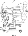
- figure 5 and figure 6 show two different views of a hoist according to one exemplary embodiment in which a user assumes a seated position
- figure 7 shows a view of the hoist according to one exemplary embodiment in which a user has assumed a standing position.
- the hoist 100 can be distinguished, as can the user.
- the exemplary hoist comprises the basic features of embodiments of the present invention such as the movable lifting arm 200, the connecting element 802, the movable handle 300, and also some optional features which may typically be present in a hoist, such as a plate 804 on which the user can place his feet, structural elements 806 on which the remaining elements may be mounted, wheels 808 whereby the hoist can be rolled around, a lower leg support 810 against which the user may place his lower legs, a motor element 812, further handles 814 for making the hoist easier to displace, etc.
- the present invention relates to a method for transferring an individual between firstly a seated or lying position and secondly a standing position, comprising:
- features of the second aspect may be independent, as described accordingly for the other aspects and their embodiments.
- the present invention relates to a handle in a hoist according to an embodiment of the first aspect, wherein the handle shifts during operation of the hoist and executes a movement relative to the lifting arm of the hoist.
- features of the third aspect may be independent, as described accordingly for the other aspects and their embodiments.
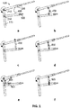
- FIGS. 1 to 4 Various configurations for obtaining a handle which shifts during operation of a hoist, and also executes a movement relative to a lifting arm, are shown in figures 1 to 4 . These configurations each comprise a hoist 100 with a movable lifting arm 200 and a movable handle 300. A connecting element and the individual are not shown on the figures.
- the movable lifting arm 200 is always rotatable about a rotation point 210, for example at the end of a stand 110; the arrow indicates the rotation of the lifting arm 200 when this performs an upward movement, e.g. while facilitating the standing movement of the individual. In the reverse movement, e.g. to a seated or lying position of the individual, the rotation is then opposite.
- the lifting arm 200 may also be movable by translation (e.g. because the stand 110 can generate an upward or downward movement of the lifting arm), or by a combination of rotation and translation.
- Figure 1 shows configurations of the first type.
- the movable handle 300 is rotatable about a rotation point 310.
- the lever arm 200 exerts an upward force on the handle 300 with a proximal point of attack (viewed from the individual) relative to the rotation point 310.
- a coupling element 400 such as a chain or belt ( figure 1a ), a shackle connection ( figure 1b ), a bridge connection ( figure 1c ), a piston ( figure 1d ), a guided chain or belt (optionally equipped with a spring 401; figure 1e ), or a sliding shackle connection (figure If).
- the maximal length of this coupling element 400 is always greater than the distance between the lifting arm 200 and the handle 300 in the first phase of operation of the hoist.
- the first phase only the lifting arm 200 moves and not the handle 300.
- the force from the lever arm 200 is transferred to the handle 300 via the coupling element 400, and during the second phase both elements move.
- both elements move on a downward movement, the same procedure is applied in reverse.
- Figure 2 shows configurations of a second type.
- the movable handle 300 is again rotatable about a rotation point 310.
- the lifting arm 200 here however exerts a downward force on the handle 300 with a distal point of attack (viewed from the individual) relative to the rotation point 310.
- a distal end of the lifting arm 200 presses on a distal end of the handle 300.
- Figure 2a shows an example with a pressure element 510 which, during the first phase of operation of the hoist, is still at a distance from the handle 300, whereby in the first phase again only the lifting arm 200 moves.
- FIG. 2b shows an example with a cam element 520, by means of which, throughout the operation of the hoist, a non-constant rotation speed is transferred from the lifting arm 200 to the handle 300. On a downward movement, again the same procedures are applied in reverse.
- Figure 3 shows configurations of a third type.
- a separate actuator 600 is used for the handle 300.
- Figure 3a shows an example in which the handle 300 is rotatable about the rotation point 310 under the influence of this actuator 600.
- Figure 3b shows an example in which the handle 300 can be retracted and/or extended under the influence of the actuator 600.
- Figure 4 shows a configuration of a fourth type.
- the handle 300 is attached to the lifting arm 200 at rotation point 320.
- a movement of the handle 300 relative to the lifting arm 200 is thereby generated.
- the movement of the handle may also be coupled to that of the lifting arm by means of interacting gearwheels.
- gear wheel size for example a differing rotation speed between the lifting arm and the handle can thus easily be obtained.
Landscapes
- Health & Medical Sciences (AREA)
- Life Sciences & Earth Sciences (AREA)
- Animal Behavior & Ethology (AREA)
- General Health & Medical Sciences (AREA)
- Public Health (AREA)
- Veterinary Medicine (AREA)
- Nursing (AREA)
- Epidemiology (AREA)
- Pain & Pain Management (AREA)
- Physical Education & Sports Medicine (AREA)
- Rehabilitation Therapy (AREA)
- Invalid Beds And Related Equipment (AREA)
Applications Claiming Priority (1)
| Application Number | Priority Date | Filing Date | Title |
|---|---|---|---|
| BE20185358A BE1026327B1 (nl) | 2018-05-30 | 2018-05-30 | Stalift met handgreep |
Publications (2)
| Publication Number | Publication Date |
|---|---|
| EP3574882A1 true EP3574882A1 (fr) | 2019-12-04 |
| EP3574882B1 EP3574882B1 (fr) | 2021-12-08 |
Family
ID=62567173
Family Applications (1)
| Application Number | Title | Priority Date | Filing Date |
|---|---|---|---|
| EP19177553.5A Active EP3574882B1 (fr) | 2018-05-30 | 2019-05-30 | Treuil comportant une poignée |
Country Status (3)
| Country | Link |
|---|---|
| US (1) | US11291600B2 (fr) |
| EP (1) | EP3574882B1 (fr) |
| BE (1) | BE1026327B1 (fr) |
Families Citing this family (3)
| Publication number | Priority date | Publication date | Assignee | Title |
|---|---|---|---|---|
| CN106659621A (zh) * | 2014-09-19 | 2017-05-10 | 松下知识产权经营株式会社 | 就座动作支援系统、就座动作支援系统的控制部的控制方法、就座动作支援系统的控制部用程序、护理带、机器人 |
| US11596828B1 (en) * | 2019-10-18 | 2023-03-07 | Enlighten Mobility, LLC | Gait trainer attachment |
| JP2022018788A (ja) * | 2020-07-16 | 2022-01-27 | 国立大学法人山梨大学 | 姿勢変換装置 |
Citations (3)
| Publication number | Priority date | Publication date | Assignee | Title |
|---|---|---|---|---|
| EP1452160A1 (fr) * | 2003-02-28 | 2004-09-01 | Crover BVBA | Dispositif de levage |
| JP2010246635A (ja) * | 2009-04-13 | 2010-11-04 | Araya Industrial Co Ltd | 立ち上がり支援装置及び立ち上がり支援方法 |
| CN106236423A (zh) * | 2016-08-24 | 2016-12-21 | 上海邦邦机器人有限公司 | 一种手起式站立轮椅车 |
Family Cites Families (17)
| Publication number | Priority date | Publication date | Assignee | Title |
|---|---|---|---|---|
| GB9126689D0 (en) * | 1991-12-17 | 1992-02-12 | Parker Roy | Invalid hoists |
| US5502851A (en) * | 1994-05-26 | 1996-04-02 | Costello; Martin D. | Assisted lifting, stand and walking device |
| NL9500482A (nl) * | 1995-03-10 | 1996-10-01 | Careflex Holding Bv | Inrichting en werkwijze voor het oprichten of plaatsen van een persoon. |
| US5892180A (en) * | 1997-02-03 | 1999-04-06 | Medcare Products, L.C. | Patient hoist and scale |
| US6119287A (en) * | 1998-05-29 | 2000-09-19 | Phillips; Barry S. | Lift and transfer apparatus for a disabled person |
| US6175973B1 (en) * | 1998-07-31 | 2001-01-23 | Hill-Rom, Inc. | Stand assist lift |
| GB9902466D0 (en) * | 1999-02-05 | 1999-03-24 | Arjo Ltd | An invalid lifting device |
| SE9902999L (sv) * | 1999-08-25 | 2000-11-27 | Liko Res And Dev Ab | Lyftsele |
| US20050217025A1 (en) * | 2004-03-31 | 2005-10-06 | Barattia Edward C | Standing frame with lift, support and transport of user |
| US7356858B2 (en) * | 2004-06-14 | 2008-04-15 | Summers Patrick D | Sit to stand support apparatus |
| US7392554B1 (en) * | 2007-04-27 | 2008-07-01 | Fong-Chin Su | Powered patient lift device |
| NL2001474C2 (nl) * | 2008-04-11 | 2009-10-13 | Joyincare Group B V | Kleminrichting ten gebruike in een tillift voor het verplaatsen van personen. |
| DE102011006359B4 (de) * | 2011-03-29 | 2015-03-19 | MATIA ROBOTICS MEKATRONiK SiSTEMLER AR-GE MÜHENDiSLiK YAZILIM SANAYi VE TiCARET ANONiM SiRICETI | Mobilitätsvorrichtung für körperbehinderte Personen und Verfahren zum Aufrichten einer sitzenden körperbehinderten Person und zum Fixieren der Person im Stand auf einer selbstfahrenden Mobilitätsvorrichtung |
| US9364379B2 (en) * | 2011-04-07 | 2016-06-14 | Standing Normal Llc | Standing mobility and/or transfer device |
| CN106659621A (zh) * | 2014-09-19 | 2017-05-10 | 松下知识产权经营株式会社 | 就座动作支援系统、就座动作支援系统的控制部的控制方法、就座动作支援系统的控制部用程序、护理带、机器人 |
| US10238564B2 (en) * | 2015-12-27 | 2019-03-26 | Mohammad Fakhrizadeh | Portable assistive lift |
| US20190054335A1 (en) * | 2017-08-16 | 2019-02-21 | Yun-Hsiu Yeh | Rehabilitation machine |
-
2018
- 2018-05-30 BE BE20185358A patent/BE1026327B1/nl active IP Right Grant
-
2019
- 2019-05-30 EP EP19177553.5A patent/EP3574882B1/fr active Active
- 2019-05-30 US US16/426,318 patent/US11291600B2/en active Active
Patent Citations (3)
| Publication number | Priority date | Publication date | Assignee | Title |
|---|---|---|---|---|
| EP1452160A1 (fr) * | 2003-02-28 | 2004-09-01 | Crover BVBA | Dispositif de levage |
| JP2010246635A (ja) * | 2009-04-13 | 2010-11-04 | Araya Industrial Co Ltd | 立ち上がり支援装置及び立ち上がり支援方法 |
| CN106236423A (zh) * | 2016-08-24 | 2016-12-21 | 上海邦邦机器人有限公司 | 一种手起式站立轮椅车 |
Also Published As
| Publication number | Publication date |
|---|---|
| BE1026327A1 (nl) | 2020-01-06 |
| BE1026327B1 (nl) | 2020-01-13 |
| US11291600B2 (en) | 2022-04-05 |
| EP3574882B1 (fr) | 2021-12-08 |
| US20190365587A1 (en) | 2019-12-05 |
Similar Documents
| Publication | Publication Date | Title |
|---|---|---|
| US11291600B2 (en) | Hoist with handle | |
| KR101667179B1 (ko) | 사용자-연계 휴먼-머신 인터페이스 시스템 및 그의 외골격 제어 방법 | |
| KR101099063B1 (ko) | 공압근육을 이용한 양팔 재활 운동 기구 | |
| EP3414061B1 (fr) | Dispositif pour renforcer la capacité de préhension d'un utilisateur | |
| EP2853249A1 (fr) | Ensemble marcheur et procédé d'utilisation pour aider une personne assise à une position debout | |
| CN113749903B (zh) | 多主动轴线的非外骨骼康复设备 | |
| JPS622534B2 (fr) | ||
| JP2012527907A (ja) | 人体下肢の治療的処置及び/又はトレーニング用装置 | |
| JP6578081B2 (ja) | 起立着座移動支援装置 | |
| CN113613581B (zh) | 多主动轴线的非外骨骼机器人康复设备 | |
| KR101694369B1 (ko) | 상지 재활 로봇 | |
| CN104582662B (zh) | 患者重新定位系统 | |
| EP3346966A1 (fr) | Dispositifs permettant aux personnes handicapées de se tenir debout, de marcher et d'activer leur corps | |
| KR102207991B1 (ko) | 시트형 근력 보조 슈트 | |
| CN109968339B (zh) | 一种无动力型可弯腰部助力器 | |
| TW202128108A (zh) | 介助用裝置 | |
| KR20210136699A (ko) | 탄성체를 갖는 중량물 취급용 상지 지원장치 | |
| CN108969252A (zh) | 一种全自动护理系统及移位方法 | |
| EP0004761B1 (fr) | Béquille | |
| CN108969249A (zh) | 一种全自动护理移位方法及背起装置 | |
| JP3185293U (ja) | リハビリ用車椅子 | |
| CN106163482A (zh) | 上肢肌力强化辅助装置 | |
| JP7383270B1 (ja) | 装着型支援ロボット装置 | |
| EP4663178A1 (fr) | Méthode de contrôle d'un exosquelette motorisé pour les membres inférieurs pendant un mouvement assis-debout | |
| CN206044863U (zh) | 一种健身轮椅 |
Legal Events
| Date | Code | Title | Description |
|---|---|---|---|
| PUAI | Public reference made under article 153(3) epc to a published international application that has entered the european phase |
Free format text: ORIGINAL CODE: 0009012 |
|
| STAA | Information on the status of an ep patent application or granted ep patent |
Free format text: STATUS: THE APPLICATION HAS BEEN PUBLISHED |
|
| AK | Designated contracting states |
Kind code of ref document: A1 Designated state(s): AL AT BE BG CH CY CZ DE DK EE ES FI FR GB GR HR HU IE IS IT LI LT LU LV MC MK MT NL NO PL PT RO RS SE SI SK SM TR |
|
| AX | Request for extension of the european patent |
Extension state: BA ME |
|
| STAA | Information on the status of an ep patent application or granted ep patent |
Free format text: STATUS: REQUEST FOR EXAMINATION WAS MADE |
|
| 17P | Request for examination filed |
Effective date: 20200604 |
|
| RBV | Designated contracting states (corrected) |
Designated state(s): AL AT BE BG CH CY CZ DE DK EE ES FI FR GB GR HR HU IE IS IT LI LT LU LV MC MK MT NL NO PL PT RO RS SE SI SK SM TR |
|
| STAA | Information on the status of an ep patent application or granted ep patent |
Free format text: STATUS: EXAMINATION IS IN PROGRESS |
|
| 17Q | First examination report despatched |
Effective date: 20200909 |
|
| GRAP | Despatch of communication of intention to grant a patent |
Free format text: ORIGINAL CODE: EPIDOSNIGR1 |
|
| STAA | Information on the status of an ep patent application or granted ep patent |
Free format text: STATUS: GRANT OF PATENT IS INTENDED |
|
| INTG | Intention to grant announced |
Effective date: 20210621 |
|
| GRAS | Grant fee paid |
Free format text: ORIGINAL CODE: EPIDOSNIGR3 |
|
| GRAA | (expected) grant |
Free format text: ORIGINAL CODE: 0009210 |
|
| STAA | Information on the status of an ep patent application or granted ep patent |
Free format text: STATUS: THE PATENT HAS BEEN GRANTED |
|
| AK | Designated contracting states |
Kind code of ref document: B1 Designated state(s): AL AT BE BG CH CY CZ DE DK EE ES FI FR GB GR HR HU IE IS IT LI LT LU LV MC MK MT NL NO PL PT RO RS SE SI SK SM TR |
|
| REG | Reference to a national code |
Ref country code: GB Ref legal event code: FG4D |
|
| REG | Reference to a national code |
Ref country code: AT Ref legal event code: REF Ref document number: 1453204 Country of ref document: AT Kind code of ref document: T Effective date: 20211215 Ref country code: CH Ref legal event code: EP |
|
| REG | Reference to a national code |
Ref country code: DE Ref legal event code: R096 Ref document number: 602019009820 Country of ref document: DE |
|
| REG | Reference to a national code |
Ref country code: IE Ref legal event code: FG4D |
|
| REG | Reference to a national code |
Ref country code: DE Ref legal event code: R081 Ref document number: 602019009820 Country of ref document: DE Owner name: HANDI-MOVE N.V., BE Free format text: FORMER OWNER: HANDI-MOVE INTERNATIONAL N.V., NINOVE, BE |
|
| REG | Reference to a national code |
Ref country code: NL Ref legal event code: FP |
|
| REG | Reference to a national code |
Ref country code: SE Ref legal event code: TRGR |
|
| RAP2 | Party data changed (patent owner data changed or rights of a patent transferred) |
Owner name: HANDI-MOVE N.V. |
|
| REG | Reference to a national code |
Ref country code: LT Ref legal event code: MG9D |
|
| REG | Reference to a national code |
Ref country code: NL Ref legal event code: PD Owner name: HANDI-MOVE N.V.; BE Free format text: DETAILS ASSIGNMENT: CHANGE OF OWNER(S), ASSIGNMENT; FORMER OWNER NAME: HANDI-MOVE INTERNATIONAL N.V. Effective date: 20220303 Ref country code: GB Ref legal event code: 732E Free format text: REGISTERED BETWEEN 20220317 AND 20220323 |
|
| PG25 | Lapsed in a contracting state [announced via postgrant information from national office to epo] |
Ref country code: RS Free format text: LAPSE BECAUSE OF FAILURE TO SUBMIT A TRANSLATION OF THE DESCRIPTION OR TO PAY THE FEE WITHIN THE PRESCRIBED TIME-LIMIT Effective date: 20211208 Ref country code: LT Free format text: LAPSE BECAUSE OF FAILURE TO SUBMIT A TRANSLATION OF THE DESCRIPTION OR TO PAY THE FEE WITHIN THE PRESCRIBED TIME-LIMIT Effective date: 20211208 Ref country code: FI Free format text: LAPSE BECAUSE OF FAILURE TO SUBMIT A TRANSLATION OF THE DESCRIPTION OR TO PAY THE FEE WITHIN THE PRESCRIBED TIME-LIMIT Effective date: 20211208 Ref country code: BG Free format text: LAPSE BECAUSE OF FAILURE TO SUBMIT A TRANSLATION OF THE DESCRIPTION OR TO PAY THE FEE WITHIN THE PRESCRIBED TIME-LIMIT Effective date: 20220308 |
|
| REG | Reference to a national code |
Ref country code: DE Ref legal event code: R081 Ref document number: 602019009820 Country of ref document: DE Owner name: HANDI-MOVE N.V., BE Free format text: FORMER OWNER: HANDI-MOVE N.V., NINOVO, BE |
|
| REG | Reference to a national code |
Ref country code: AT Ref legal event code: MK05 Ref document number: 1453204 Country of ref document: AT Kind code of ref document: T Effective date: 20211208 |
|
| PG25 | Lapsed in a contracting state [announced via postgrant information from national office to epo] |
Ref country code: NO Free format text: LAPSE BECAUSE OF FAILURE TO SUBMIT A TRANSLATION OF THE DESCRIPTION OR TO PAY THE FEE WITHIN THE PRESCRIBED TIME-LIMIT Effective date: 20220308 Ref country code: LV Free format text: LAPSE BECAUSE OF FAILURE TO SUBMIT A TRANSLATION OF THE DESCRIPTION OR TO PAY THE FEE WITHIN THE PRESCRIBED TIME-LIMIT Effective date: 20211208 Ref country code: HR Free format text: LAPSE BECAUSE OF FAILURE TO SUBMIT A TRANSLATION OF THE DESCRIPTION OR TO PAY THE FEE WITHIN THE PRESCRIBED TIME-LIMIT Effective date: 20211208 Ref country code: GR Free format text: LAPSE BECAUSE OF FAILURE TO SUBMIT A TRANSLATION OF THE DESCRIPTION OR TO PAY THE FEE WITHIN THE PRESCRIBED TIME-LIMIT Effective date: 20220309 Ref country code: ES Free format text: LAPSE BECAUSE OF FAILURE TO SUBMIT A TRANSLATION OF THE DESCRIPTION OR TO PAY THE FEE WITHIN THE PRESCRIBED TIME-LIMIT Effective date: 20211208 |
|
| PG25 | Lapsed in a contracting state [announced via postgrant information from national office to epo] |
Ref country code: SM Free format text: LAPSE BECAUSE OF FAILURE TO SUBMIT A TRANSLATION OF THE DESCRIPTION OR TO PAY THE FEE WITHIN THE PRESCRIBED TIME-LIMIT Effective date: 20211208 Ref country code: SK Free format text: LAPSE BECAUSE OF FAILURE TO SUBMIT A TRANSLATION OF THE DESCRIPTION OR TO PAY THE FEE WITHIN THE PRESCRIBED TIME-LIMIT Effective date: 20211208 Ref country code: RO Free format text: LAPSE BECAUSE OF FAILURE TO SUBMIT A TRANSLATION OF THE DESCRIPTION OR TO PAY THE FEE WITHIN THE PRESCRIBED TIME-LIMIT Effective date: 20211208 Ref country code: PT Free format text: LAPSE BECAUSE OF FAILURE TO SUBMIT A TRANSLATION OF THE DESCRIPTION OR TO PAY THE FEE WITHIN THE PRESCRIBED TIME-LIMIT Effective date: 20220408 Ref country code: EE Free format text: LAPSE BECAUSE OF FAILURE TO SUBMIT A TRANSLATION OF THE DESCRIPTION OR TO PAY THE FEE WITHIN THE PRESCRIBED TIME-LIMIT Effective date: 20211208 Ref country code: CZ Free format text: LAPSE BECAUSE OF FAILURE TO SUBMIT A TRANSLATION OF THE DESCRIPTION OR TO PAY THE FEE WITHIN THE PRESCRIBED TIME-LIMIT Effective date: 20211208 |
|
| PG25 | Lapsed in a contracting state [announced via postgrant information from national office to epo] |
Ref country code: PL Free format text: LAPSE BECAUSE OF FAILURE TO SUBMIT A TRANSLATION OF THE DESCRIPTION OR TO PAY THE FEE WITHIN THE PRESCRIBED TIME-LIMIT Effective date: 20211208 Ref country code: AT Free format text: LAPSE BECAUSE OF FAILURE TO SUBMIT A TRANSLATION OF THE DESCRIPTION OR TO PAY THE FEE WITHIN THE PRESCRIBED TIME-LIMIT Effective date: 20211208 |
|
| REG | Reference to a national code |
Ref country code: DE Ref legal event code: R097 Ref document number: 602019009820 Country of ref document: DE |
|
| PG25 | Lapsed in a contracting state [announced via postgrant information from national office to epo] |
Ref country code: IS Free format text: LAPSE BECAUSE OF FAILURE TO SUBMIT A TRANSLATION OF THE DESCRIPTION OR TO PAY THE FEE WITHIN THE PRESCRIBED TIME-LIMIT Effective date: 20220408 |
|
| PLBE | No opposition filed within time limit |
Free format text: ORIGINAL CODE: 0009261 |
|
| STAA | Information on the status of an ep patent application or granted ep patent |
Free format text: STATUS: NO OPPOSITION FILED WITHIN TIME LIMIT |
|
| PG25 | Lapsed in a contracting state [announced via postgrant information from national office to epo] |
Ref country code: DK Free format text: LAPSE BECAUSE OF FAILURE TO SUBMIT A TRANSLATION OF THE DESCRIPTION OR TO PAY THE FEE WITHIN THE PRESCRIBED TIME-LIMIT Effective date: 20211208 Ref country code: AL Free format text: LAPSE BECAUSE OF FAILURE TO SUBMIT A TRANSLATION OF THE DESCRIPTION OR TO PAY THE FEE WITHIN THE PRESCRIBED TIME-LIMIT Effective date: 20211208 |
|
| 26N | No opposition filed |
Effective date: 20220909 |
|
| PG25 | Lapsed in a contracting state [announced via postgrant information from national office to epo] |
Ref country code: SI Free format text: LAPSE BECAUSE OF FAILURE TO SUBMIT A TRANSLATION OF THE DESCRIPTION OR TO PAY THE FEE WITHIN THE PRESCRIBED TIME-LIMIT Effective date: 20211208 |
|
| REG | Reference to a national code |
Ref country code: CH Ref legal event code: PL |
|
| REG | Reference to a national code |
Ref country code: BE Ref legal event code: MM Effective date: 20220531 |
|
| PG25 | Lapsed in a contracting state [announced via postgrant information from national office to epo] |
Ref country code: MC Free format text: LAPSE BECAUSE OF FAILURE TO SUBMIT A TRANSLATION OF THE DESCRIPTION OR TO PAY THE FEE WITHIN THE PRESCRIBED TIME-LIMIT Effective date: 20211208 Ref country code: LU Free format text: LAPSE BECAUSE OF NON-PAYMENT OF DUE FEES Effective date: 20220530 Ref country code: LI Free format text: LAPSE BECAUSE OF NON-PAYMENT OF DUE FEES Effective date: 20220531 Ref country code: CH Free format text: LAPSE BECAUSE OF NON-PAYMENT OF DUE FEES Effective date: 20220531 |
|
| PG25 | Lapsed in a contracting state [announced via postgrant information from national office to epo] |
Ref country code: IE Free format text: LAPSE BECAUSE OF NON-PAYMENT OF DUE FEES Effective date: 20220530 |
|
| PG25 | Lapsed in a contracting state [announced via postgrant information from national office to epo] |
Ref country code: BE Free format text: LAPSE BECAUSE OF NON-PAYMENT OF DUE FEES Effective date: 20220531 |
|
| PG25 | Lapsed in a contracting state [announced via postgrant information from national office to epo] |
Ref country code: HU Free format text: LAPSE BECAUSE OF FAILURE TO SUBMIT A TRANSLATION OF THE DESCRIPTION OR TO PAY THE FEE WITHIN THE PRESCRIBED TIME-LIMIT; INVALID AB INITIO Effective date: 20190530 |
|
| PG25 | Lapsed in a contracting state [announced via postgrant information from national office to epo] |
Ref country code: MK Free format text: LAPSE BECAUSE OF FAILURE TO SUBMIT A TRANSLATION OF THE DESCRIPTION OR TO PAY THE FEE WITHIN THE PRESCRIBED TIME-LIMIT Effective date: 20211208 Ref country code: CY Free format text: LAPSE BECAUSE OF FAILURE TO SUBMIT A TRANSLATION OF THE DESCRIPTION OR TO PAY THE FEE WITHIN THE PRESCRIBED TIME-LIMIT Effective date: 20211208 |
|
| PG25 | Lapsed in a contracting state [announced via postgrant information from national office to epo] |
Ref country code: MT Free format text: LAPSE BECAUSE OF FAILURE TO SUBMIT A TRANSLATION OF THE DESCRIPTION OR TO PAY THE FEE WITHIN THE PRESCRIBED TIME-LIMIT Effective date: 20211208 |
|
| PGFP | Annual fee paid to national office [announced via postgrant information from national office to epo] |
Ref country code: NL Payment date: 20250521 Year of fee payment: 7 |
|
| PGFP | Annual fee paid to national office [announced via postgrant information from national office to epo] |
Ref country code: DE Payment date: 20250521 Year of fee payment: 7 |
|
| PGFP | Annual fee paid to national office [announced via postgrant information from national office to epo] |
Ref country code: GB Payment date: 20250527 Year of fee payment: 7 |
|
| PGFP | Annual fee paid to national office [announced via postgrant information from national office to epo] |
Ref country code: IT Payment date: 20250527 Year of fee payment: 7 |
|
| PGFP | Annual fee paid to national office [announced via postgrant information from national office to epo] |
Ref country code: FR Payment date: 20250528 Year of fee payment: 7 |
|
| PGFP | Annual fee paid to national office [announced via postgrant information from national office to epo] |
Ref country code: SE Payment date: 20250521 Year of fee payment: 7 |
|
| PG25 | Lapsed in a contracting state [announced via postgrant information from national office to epo] |
Ref country code: TR Free format text: LAPSE BECAUSE OF FAILURE TO SUBMIT A TRANSLATION OF THE DESCRIPTION OR TO PAY THE FEE WITHIN THE PRESCRIBED TIME-LIMIT Effective date: 20211208 |