EP3574945B1 - Dispositif de protection comprenant un couvercle de protection à griffes fixes - Google Patents
Dispositif de protection comprenant un couvercle de protection à griffes fixes Download PDFInfo
- Publication number
- EP3574945B1 EP3574945B1 EP18305671.2A EP18305671A EP3574945B1 EP 3574945 B1 EP3574945 B1 EP 3574945B1 EP 18305671 A EP18305671 A EP 18305671A EP 3574945 B1 EP3574945 B1 EP 3574945B1
- Authority
- EP
- European Patent Office
- Prior art keywords
- claws
- needle
- protective device
- cover
- protective
- Prior art date
- Legal status (The legal status is an assumption and is not a legal conclusion. Google has not performed a legal analysis and makes no representation as to the accuracy of the status listed.)
- Active
Links
Images

Classifications
-
- A—HUMAN NECESSITIES
- A61—MEDICAL OR VETERINARY SCIENCE; HYGIENE
- A61M—DEVICES FOR INTRODUCING MEDIA INTO, OR ONTO, THE BODY; DEVICES FOR TRANSDUCING BODY MEDIA OR FOR TAKING MEDIA FROM THE BODY; DEVICES FOR PRODUCING OR ENDING SLEEP OR STUPOR
- A61M5/00—Devices for bringing media into the body in a subcutaneous, intra-vascular or intramuscular way; Accessories therefor, e.g. filling or cleaning devices, arm rests
- A61M5/14—Infusion devices, e.g. infusing by gravity; Blood infusion; Accessories therefor
- A61M5/158—Needles for infusions; Accessories therefor, e.g. for inserting infusion needles, or for holding them on the body
-
- A—HUMAN NECESSITIES
- A61—MEDICAL OR VETERINARY SCIENCE; HYGIENE
- A61M—DEVICES FOR INTRODUCING MEDIA INTO, OR ONTO, THE BODY; DEVICES FOR TRANSDUCING BODY MEDIA OR FOR TAKING MEDIA FROM THE BODY; DEVICES FOR PRODUCING OR ENDING SLEEP OR STUPOR
- A61M5/00—Devices for bringing media into the body in a subcutaneous, intra-vascular or intramuscular way; Accessories therefor, e.g. filling or cleaning devices, arm rests
- A61M5/178—Syringes
-
- A—HUMAN NECESSITIES
- A61—MEDICAL OR VETERINARY SCIENCE; HYGIENE
- A61M—DEVICES FOR INTRODUCING MEDIA INTO, OR ONTO, THE BODY; DEVICES FOR TRANSDUCING BODY MEDIA OR FOR TAKING MEDIA FROM THE BODY; DEVICES FOR PRODUCING OR ENDING SLEEP OR STUPOR
- A61M5/00—Devices for bringing media into the body in a subcutaneous, intra-vascular or intramuscular way; Accessories therefor, e.g. filling or cleaning devices, arm rests
- A61M5/178—Syringes
- A61M5/31—Details
- A61M5/3129—Syringe barrels
-
- A—HUMAN NECESSITIES
- A61—MEDICAL OR VETERINARY SCIENCE; HYGIENE
- A61M—DEVICES FOR INTRODUCING MEDIA INTO, OR ONTO, THE BODY; DEVICES FOR TRANSDUCING BODY MEDIA OR FOR TAKING MEDIA FROM THE BODY; DEVICES FOR PRODUCING OR ENDING SLEEP OR STUPOR
- A61M5/00—Devices for bringing media into the body in a subcutaneous, intra-vascular or intramuscular way; Accessories therefor, e.g. filling or cleaning devices, arm rests
- A61M5/178—Syringes
- A61M5/31—Details
- A61M5/32—Needles; Details of needles pertaining to their connection with syringe or hub; Accessories for bringing the needle into, or holding the needle on, the body; Devices for protection of needles
-
- A—HUMAN NECESSITIES
- A61—MEDICAL OR VETERINARY SCIENCE; HYGIENE
- A61M—DEVICES FOR INTRODUCING MEDIA INTO, OR ONTO, THE BODY; DEVICES FOR TRANSDUCING BODY MEDIA OR FOR TAKING MEDIA FROM THE BODY; DEVICES FOR PRODUCING OR ENDING SLEEP OR STUPOR
- A61M5/00—Devices for bringing media into the body in a subcutaneous, intra-vascular or intramuscular way; Accessories therefor, e.g. filling or cleaning devices, arm rests
- A61M5/178—Syringes
- A61M5/31—Details
- A61M5/32—Needles; Details of needles pertaining to their connection with syringe or hub; Accessories for bringing the needle into, or holding the needle on, the body; Devices for protection of needles
- A61M5/3202—Devices for protection of the needle before use, e.g. caps
-
- A—HUMAN NECESSITIES
- A61—MEDICAL OR VETERINARY SCIENCE; HYGIENE
- A61M—DEVICES FOR INTRODUCING MEDIA INTO, OR ONTO, THE BODY; DEVICES FOR TRANSDUCING BODY MEDIA OR FOR TAKING MEDIA FROM THE BODY; DEVICES FOR PRODUCING OR ENDING SLEEP OR STUPOR
- A61M5/00—Devices for bringing media into the body in a subcutaneous, intra-vascular or intramuscular way; Accessories therefor, e.g. filling or cleaning devices, arm rests
- A61M5/178—Syringes
- A61M5/31—Details
- A61M2005/3103—Leak prevention means for distal end of syringes, i.e. syringe end for mounting a needle
- A61M2005/3107—Leak prevention means for distal end of syringes, i.e. syringe end for mounting a needle for needles
- A61M2005/3109—Caps sealing the needle bore by use of, e.g. air-hardening adhesive, elastomer or epoxy resin
-
- A—HUMAN NECESSITIES
- A61—MEDICAL OR VETERINARY SCIENCE; HYGIENE
- A61M—DEVICES FOR INTRODUCING MEDIA INTO, OR ONTO, THE BODY; DEVICES FOR TRANSDUCING BODY MEDIA OR FOR TAKING MEDIA FROM THE BODY; DEVICES FOR PRODUCING OR ENDING SLEEP OR STUPOR
- A61M2205/00—General characteristics of the apparatus
- A61M2205/27—General characteristics of the apparatus preventing use
- A61M2205/273—General characteristics of the apparatus preventing use preventing reuse, e.g. of disposables
Definitions
- the invention is directed at a protective device comprising a protective cover intended to be gripped on a needle-protecting cap of a syringe.
- a protective cover having claws arranged in order to grip the said needle-protecting cap and being able to take the latter away upon the removal of the said cover.
- a syringe needle having a needle-protecting cap made of a flexible material and a protective cover made of a rigid material adapted to cover the needle-protecting.
- Such protective devices are commonly used for safety reasons. They also facilitate the removal of the needle-protecting cap which is held within the protective cover upon the removal of the latter.
- WO02/11799A1 discloses one example of these protective devices.
- the protective cover In order to hold the needle-protecting cap, the protective cover is equipped with tilting claws.
- the object of these claws is to enable to fit the cover on the needle-protecting cap without pushing away said cap, as it may lead to damages to the end of the needle conventionally sticking into the cap.
- This design allows a lesser strength for fitting the cover on the needle-protecting cap. It also requires a stronger strength for removing the cover from this cap, which enables the withdrawal of the cover together with the cap, this latter being kept inside the cover by the claws.
- the object of the present invention is therefore to provide with a protective device with an improved reliability in terms of life span.
- the invention is directed at a protective device as defined in claim 1.
- the invention can optionally comprise one or several features chosen among the following features:
- This injection device takes the benefits of the protective cover according to the invention.
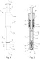
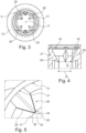
- Figures 1 and 2 show an example of an injection device 1 according to the invention.
- This injection device can be, as in this example, a single-use injection device.
- the injection device 1 comprises a protective device 10 and a syringe 2, here a prefilled syringe.
- the protective device 10 comprises a body, which here forms a protective case in which the syringe 2 is inserted and fixed.
- the protective case comprises two case portions 11, 12. These latter can be tubular.
- the first case portion 11 comprises in this example two tubular elements, front element 11b and rear element 11a, adapted to fit together as a continuation of one another, and to be preassembled before putting in place initially prefilled syringe 2 in the protective case 11, 12.
- this first case portion 11 could be one single element made in a single block piece.
- This first case portion is called here after the holding portion 11.
- the second case portion 12 corresponds to the case 11 end and is made in one block piece with the front element 11b. However, this second case portion is here separable.
- this second case portion 12 is delimited by a frangible zone 16, which comprises holes and connecting frangible parts 18, these latter connecting the second case portion 12 to the front element 11b.
- This second case portion 12 forms the protective end-piece of the protective device 10, that is to say the protective cover of the protective device 10. Said second case portion 12 is be called herein below the cover 12.
- the syringe 2 can be a traditional type of syringe, such as one made of glass for example, comprising:
- the protective device 10 is adapted so that when the syringe 2 is being put in place inside the protective device 10, the nose 6, the needle 7, and the needle-protecting cap 8 extend into the cover 12.
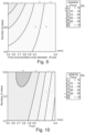
- the cover 12 has an internal surface 13 and comprises internal claws protruding from this internal surface 13.
- the claws 20 are integral with the protective cover 12 and fixed in respect of the internal surface 13.
- the claws 20 can for example be integrally moulded with the cover 12.
- the cover 12 comprises four internal claws 20.
- each claw has a base 21, which corresponds to the junction of the claw 20 with the internal surface 13.
- Each claws 20 has also a free end in the form of a point 22.
- the claws 20 are shaped so that the initial diameter D1 of the first circumscribed circle 30 is less than the diameter of the needle-protecting cap 8, so that it is necessary to force this cap 8 through the points 22 of the claws 20, when inserting the syringe 2 completely inside the protective case 11, 12.
- the protective device 10 is adapted to needle-protecting caps having a diameter higher than the initial diameter of the first circumscribed circle 30.
- the diameter D1 of this first circumscribed circle 30 can be equal or more than 3,4 mm and equal or less than 3,9 mm. This improves the efficiency compromise between the force for forcing the needle-protecting cap 8 inside the cover 12 and the force retaining the needle-protecting cap 8 in the cover 12.
- the efficiency compromise is improved when the diameter D1 of the first circumscribed circle 30 is equal or more than 3,4 mm and equal or less than 3,9 mm, even improved when it is equal or more than 3,4 mm and equal or less than 3,8 mm, and even improved when it is equal or more than 3,5 mm and equal or less than 3,7 mm.
- this diameter D1 is about 3,6 mm.
- claws 20 are uniformly distributed around the longitudinal axis A of said cover 12, which is also the longitudinal axis of the protective device 10 and of the injection device 1. Applicant has found that such distribution provides a better efficiency compromise.
- This longitudinal axis A runs through the needle 7, once the syringe 2 is inserted in the protective case 11, 12, and is moreover aligned with the center of the first circumscribed circle 30.
- the base 21 of each claws 20 has a section that is its largest section. Therefore, creep at the base 21 of each of the claws is lessen.
- each of these claws 20 has the shape of a tetrahedron, the front face of which being visible in figures 3, 5 and 8 .
- the syringe 2 inside the protective device 10 is implemented as follows.
- the syringe 2 is inserted through rear opening 19 of the holding part 11 and slide from rear of the holding part 11 towards its end.
- the connecting frangible parts 18 are broken and the claws 20 penetrates deeper inside the needle-protecting cap 8 and guarantees entrainment of the needle-protecting cap 8 away from the needle 7.
- the protective device 10 can comprise locking means 15 for rotational and translational locking of the syringe 2 inside this holding portion 11.
- the protective device 10 can comprise elastic means 14, for example comprising a spring, which are able of bringing about an automatic withdrawal of the syringe 2 inside the protective case 11 at the end of the injection.
- the invention in general is not limited to the number of claws.
- these claws 120 can be uniformly distributed around the longitudinal axis A' and a first circumscribed circle 130 can also be defined here, passing on claws 120 points.
- Uniform distribution in other words symmetric distribution of the claws in respect of said longitudinal axis, provides better results. That is to say, referring for example to first and the second embodiment and as can be seen respectively on figures 8 and 6 , in a plane perpendicular to said longitudinal axis A, A' and passing through the points 22 of the claws 20, 120, the angles ⁇ , ⁇ ' between the points of adjacent claws are identical or almost identical.
- the cover 212 has four claws 220 that are arranged such that two plan of symmetry P"1, P"2 can be defined: the first plan P"1 passing in the middle of the of the biggest angles between the points of adjacent claws, and the second plan P"2 passing in the middle of the smallest angles between the points of adjacent claws.
- Results are further improved when, in a plane perpendicular to said longitudinal axis A" and passing through the points of the claws 220, the angles between the points of adjacent claws being different, the smallest angle ⁇ " among these angles has a value that is equal or more than 70° and equal or less than 90°. Here this value is 70°.
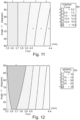
- Figures 9 and 10 schematic diagrams are showing force values in respect of the number of claws and the first circumscribed circle 30 diameter D1 (Feed). Zones with (+) have good results, zones with (-) have bad results. Zones with no sign are intermediate zones.
Landscapes
- Health & Medical Sciences (AREA)
- Vascular Medicine (AREA)
- Engineering & Computer Science (AREA)
- Anesthesiology (AREA)
- Biomedical Technology (AREA)
- Heart & Thoracic Surgery (AREA)
- Hematology (AREA)
- Life Sciences & Earth Sciences (AREA)
- Animal Behavior & Ethology (AREA)
- General Health & Medical Sciences (AREA)
- Public Health (AREA)
- Veterinary Medicine (AREA)
- Infusion, Injection, And Reservoir Apparatuses (AREA)
Claims (13)
- Dispositif de protection (10 ; 110 ; 210) comprenant un couvercle de protection (12) et comprenant en outreun capuchon de protection d'aiguille (8) à l'intérieur du couvercle de protection (12), dans lequel le couvercle de protection (12) est constitué d'un matériau rigide,destiné à être saisi sur le capuchon de protection d'aiguille (8), constitué d'un matériau souple, d'une seringue (2) pour éloigner le capuchon de protection d'aiguille (8) de l'aiguille lors du retrait dudit capuchon de protection (12), ledit capuchon de protection (12) ayant une surface interne (13 ; 113 ; 213) et comprenant des griffes (20 ; 120 ; 220) faisant saillie à partir de cette surface interne, lesdites griffes (20 ; 120 ; 220) conçues pour saisir le capuchon de protection d'aiguille (8) et les griffes (20 ; 120 ; 220) ayant une extrémité libre en forme d'une pointe (22) disposée de manière à s'enfoncer dans le capuchon de protection d'aiguille (8), dans lequel les griffes (20 ; 120 ; 220) :- sont orientées vers l'aval,- sont partie intégrante du couvercle de protection (12),- et caractérisé en ce que les griffes (20 ; 120 ; 220) sont fixées par rapport à ladite surface interne (13 ; 113 ; 213) sans aucune articulation,
- Dispositif de protection (10 ; 110 ; 210) selon la revendication 1, dans lequel le couvercle de protection (12) ne comprend que quatre ou cinq desdites griffes (20 ; 120 ; 220).
- Dispositif de protection (10 ; 110 ; 210) selon la revendication 2, comprenant seulement quatre desdites griffes (20 ; 120 ; 220).
- Dispositif de protection (10 ; 110 ; 210) selon l'une quelconque des revendications précédentes, dans lequel le diamètre du cercle (30) passant par la pointe (22) des griffes est supérieur ou égal à 3,4 mm et inférieur ou égal à 3,9 mm.
- Dispositif de protection (10 ; 110 ; 210) selon la revendication 4, dans lequel le diamètre du cercle (30 ; 130 ; 230) passant par la pointe (22) des griffes est supérieur ou égal à 3,4 mm et inférieur ou égal à 3,8 mm.
- Dispositif de protection (10 ; 110 ; 210) selon la revendication 5, dans lequel le diamètre du cercle (30 ; 130 ; 230) passant par la pointe (22) des griffes (20 ; 120 ; 220) est supérieur ou égal à 3,5 mm et inférieur ou égal à 3,7 mm.
- Dispositif de protection (10 ; 110 ; 210) selon l'une quelconque des revendications précédentes, dans lequel lesdites griffes (20 ; 120 ; 220) sont réparties autour d'un axe longitudinal (A) dudit couvercle (12).
- Dispositif de protection (10 ; 110 ; 210) selon la revendication 7, dans lequel les griffes (20 ; 120 ; 220) sont réparties de manière approximativement symétrique par rapport audit axe longitudinal (A ; A') et/ou par rapport à un plan (P "1, P "2) comprenant ledit axe longitudinal.
- Dispositif de protection (10 ; 110 ; 210) selon la revendication 7 ou selon la revendication 8, dans lequel, dans un plan perpendiculaire audit axe longitudinal (A") et passant par les pointes (22) des griffes (220), les angles entre les pointes des griffes adjacentes sont différents, le plus petit de ces angles (α") ayant une valeur qui est égale ou supérieure à 70° et égale ou inférieure à 90°.
- Dispositif de protection (10 ; 110 ; 210) selon l'une quelconque des revendications précédentes, dans lequel pour au moins une desdites griffes (20 ; 120 ; 220), l'intersection de cette griffe avec la surface interne (13 ; 113 ; 213) dudit couvercle (12 ; 112 ; 212) est la plus grande section de cette griffe correspondante.
- Dispositif de protection (10 ; 110 ; 210) selon l'une quelconque des revendications précédentes, dans lequel au moins une des griffes (20 ; 120 ; 220) possède une pointe (22) qui se rétrécit fortement par rapport au reste de la griffe.
- Dispositif de protection (10 ; 110 ; 210) selon la revendication 1, comprenant un corps (11, 12) pour l'insertion d'une seringue (2), dans lequel le corps (11, 12) a une partie séparable délimitée par une zone frangible (6), ladite partie séparable constituant le couvercle de protection (12 ; 112 ; 212).
- Dispositif d'injection (1) comprenant un dispositif de protection (10 ; 110 ; 210) selon la revendication 12,
dans lequel une seringue remplie (2) est montée à l'intérieur dudit corps (11,12), une aiguille (7) de cette seringue étant insérée à l'intérieur dudit capuchon de protection d'aiguille (8).
Priority Applications (8)
| Application Number | Priority Date | Filing Date | Title |
|---|---|---|---|
| EP18305671.2A EP3574945B1 (fr) | 2018-05-31 | 2018-05-31 | Dispositif de protection comprenant un couvercle de protection à griffes fixes |
| MYPI2019002954A MY199172A (en) | 2018-05-31 | 2019-05-24 | Protective device comprising a protective cover with fixed claws |
| RU2019116551A RU2727453C1 (ru) | 2018-05-31 | 2019-05-29 | Защитное устройство, содержащее защитный чехол с неподвижными зубцами |
| PH12019000203A PH12019000203A1 (en) | 2018-05-31 | 2019-05-29 | Protective device comprising a protective cover with fixed claws |
| ZA2019/03444A ZA201903444B (en) | 2018-05-31 | 2019-05-30 | Protective device comprising a protective cover with fixed claws |
| UAA201905926A UA125178C2 (uk) | 2018-05-31 | 2019-05-30 | Захисний пристрій, що містить захисну кришку з нерухомими лапками |
| BR102019011175-5A BR102019011175B1 (pt) | 2018-05-31 | 2019-05-30 | Dispositivo de proteção, e, dispositivo de injeção |
| CN201910469931.9A CN110548199A (zh) | 2018-05-31 | 2019-05-31 | 包括带有固定爪的保护盖的保护装置及注射装置 |
Applications Claiming Priority (1)
| Application Number | Priority Date | Filing Date | Title |
|---|---|---|---|
| EP18305671.2A EP3574945B1 (fr) | 2018-05-31 | 2018-05-31 | Dispositif de protection comprenant un couvercle de protection à griffes fixes |
Publications (3)
| Publication Number | Publication Date |
|---|---|
| EP3574945A1 EP3574945A1 (fr) | 2019-12-04 |
| EP3574945B1 true EP3574945B1 (fr) | 2024-07-10 |
| EP3574945C0 EP3574945C0 (fr) | 2024-07-10 |
Family
ID=62567568
Family Applications (1)
| Application Number | Title | Priority Date | Filing Date |
|---|---|---|---|
| EP18305671.2A Active EP3574945B1 (fr) | 2018-05-31 | 2018-05-31 | Dispositif de protection comprenant un couvercle de protection à griffes fixes |
Country Status (7)
| Country | Link |
|---|---|
| EP (1) | EP3574945B1 (fr) |
| CN (1) | CN110548199A (fr) |
| MY (1) | MY199172A (fr) |
| PH (1) | PH12019000203A1 (fr) |
| RU (1) | RU2727453C1 (fr) |
| UA (1) | UA125178C2 (fr) |
| ZA (1) | ZA201903444B (fr) |
Family Cites Families (11)
| Publication number | Priority date | Publication date | Assignee | Title |
|---|---|---|---|---|
| US5147325A (en) * | 1991-05-03 | 1992-09-15 | Sherwood Medical Company | Rigid needle shield |
| FR2799376B1 (fr) * | 1999-10-07 | 2002-01-18 | Marc Brunel | Dispositif d'injection a usage unique |
| FR2803530B1 (fr) | 2000-01-07 | 2002-07-19 | Sanofi Synthelabo | Dispositif d'injection d'une dose de liquide notamment medicamenteux |
| FR2812817B1 (fr) | 2000-08-09 | 2002-10-31 | Sanofi Synthelabo | Dispositif de protection d'une aiguille de seringue |
| JP2012529322A (ja) * | 2009-06-12 | 2012-11-22 | ノボ・ノルデイスク・エー/エス | 針アセンブリのためのキャップ機能を有する薬剤送達装置 |
| FR2985669B1 (fr) * | 2012-01-12 | 2015-10-02 | Biocorp Rech Et Dev | Dispositif de protection de l'aiguille d'une seringue |
| JP6273087B2 (ja) * | 2012-10-25 | 2018-01-31 | 大成化工株式会社 | シリンジ |
| FR3011473B1 (fr) * | 2013-10-08 | 2015-12-18 | Aptar Stelmi Sas | Dispositif de protection pour aiguille de seringue. |
| EP2878321A1 (fr) * | 2013-11-28 | 2015-06-03 | Sanofi-Aventis Deutschland GmbH | Dispositif de sécurité d'aiguille et dispositif d'administration de médicament |
| CA2974585C (fr) * | 2015-01-26 | 2023-01-24 | Biocorp Production | Dispositif de protection d'une aiguille, seringue equipee d'un tel dispositif et procede de fabrication de seringues pre-remplies a aiguille collee |
| TW201707741A (zh) * | 2015-06-03 | 2017-03-01 | 賽諾菲阿凡提斯德意志有限公司 | 針頭護罩之抓握器、蓋子、自動注射器及製造抓握器之方法 |
-
2018
- 2018-05-31 EP EP18305671.2A patent/EP3574945B1/fr active Active
-
2019
- 2019-05-24 MY MYPI2019002954A patent/MY199172A/en unknown
- 2019-05-29 RU RU2019116551A patent/RU2727453C1/ru active
- 2019-05-29 PH PH12019000203A patent/PH12019000203A1/en unknown
- 2019-05-30 ZA ZA2019/03444A patent/ZA201903444B/en unknown
- 2019-05-30 UA UAA201905926A patent/UA125178C2/uk unknown
- 2019-05-31 CN CN201910469931.9A patent/CN110548199A/zh active Pending
Also Published As
| Publication number | Publication date |
|---|---|
| ZA201903444B (en) | 2020-02-26 |
| RU2727453C1 (ru) | 2020-07-21 |
| EP3574945A1 (fr) | 2019-12-04 |
| EP3574945C0 (fr) | 2024-07-10 |
| CN110548199A (zh) | 2019-12-10 |
| BR102019011175A2 (pt) | 2019-12-17 |
| UA125178C2 (uk) | 2022-01-26 |
| MY199172A (en) | 2023-10-18 |
| PH12019000203A1 (en) | 2020-02-17 |
Similar Documents
| Publication | Publication Date | Title |
|---|---|---|
| US4973309A (en) | Disposable syringe | |
| EP2361076B1 (fr) | Dispositif pourvu d'une aiguille pour accéder à un flacon | |
| US20040116854A1 (en) | Syringe retractable needle and method | |
| EP0107874B1 (fr) | Dispositif automatique d'injections | |
| US7094223B2 (en) | Device for protecting a syringe needle | |
| CN112516420B (zh) | 用于锁定使用后的注射器的柱塞杆并防止注射器再使用的装置以及注射器组件 | |
| US20120157928A1 (en) | luer lock adaptor | |
| JP6626147B2 (ja) | 再使用防止のためのサムプレスの破断容易機能 | |
| EP2700425A1 (fr) | Corps à bouchon fixé, seringue pré-remplie et bouchon à élément de liaison fixé | |
| RS59251B1 (sr) | Sklop skidača poklopca štitnika igle | |
| HU226533B1 (en) | Syringes | |
| JP2022051879A (ja) | セプタム固定 | |
| CZ20021164A3 (cs) | Injekční zařízení na jedno pouľití | |
| CZ297330B6 (cs) | Injekcní stríkacka odolná proti nedovolené manipulaci a zpusob její montáze | |
| US12465741B2 (en) | Adaptor for connecting a drug delivery device to a connector | |
| HUT69453A (en) | Holder for cartridge-needle unit | |
| KR20100016555A (ko) | 캐뉼러를 홀딩하여 주사 펜에 분리가능하게 배치하기 위한 장치 | |
| CN114098919A (zh) | 植入物注射器 | |
| KR101810886B1 (ko) | 주사바늘 모델별 교체사용이 가능한 주사기용 2단 핑거그립 홀더 | |
| EP1976435B1 (fr) | Lancette | |
| EP3574945A1 (fr) | Dispositif de protection comprenant un couvercle de protection à griffes fixes | |
| KR20160053701A (ko) | 치과 인상용 트레이 | |
| US11642152B2 (en) | Cannula holder | |
| EP3226941A1 (fr) | Système de piston de seringue à géométrie filetée à verrouillage automatique | |
| US20110196292A1 (en) | Injector and two-chamber system having sealing container adapter |
Legal Events
| Date | Code | Title | Description |
|---|---|---|---|
| PUAI | Public reference made under article 153(3) epc to a published international application that has entered the european phase |
Free format text: ORIGINAL CODE: 0009012 |
|
| STAA | Information on the status of an ep patent application or granted ep patent |
Free format text: STATUS: THE APPLICATION HAS BEEN PUBLISHED |
|
| AK | Designated contracting states |
Kind code of ref document: A1 Designated state(s): AL AT BE BG CH CY CZ DE DK EE ES FI FR GB GR HR HU IE IS IT LI LT LU LV MC MK MT NL NO PL PT RO RS SE SI SK SM TR |
|
| AX | Request for extension of the european patent |
Extension state: BA ME |
|
| STAA | Information on the status of an ep patent application or granted ep patent |
Free format text: STATUS: REQUEST FOR EXAMINATION WAS MADE |
|
| 17P | Request for examination filed |
Effective date: 20200501 |
|
| RBV | Designated contracting states (corrected) |
Designated state(s): AL AT BE BG CH CY CZ DE DK EE ES FI FR GB GR HR HU IE IS IT LI LT LU LV MC MK MT NL NO PL PT RO RS SE SI SK SM TR |
|
| STAA | Information on the status of an ep patent application or granted ep patent |
Free format text: STATUS: EXAMINATION IS IN PROGRESS |
|
| 17Q | First examination report despatched |
Effective date: 20221108 |
|
| GRAP | Despatch of communication of intention to grant a patent |
Free format text: ORIGINAL CODE: EPIDOSNIGR1 |
|
| STAA | Information on the status of an ep patent application or granted ep patent |
Free format text: STATUS: GRANT OF PATENT IS INTENDED |
|
| INTG | Intention to grant announced |
Effective date: 20240314 |
|
| GRAS | Grant fee paid |
Free format text: ORIGINAL CODE: EPIDOSNIGR3 |
|
| GRAA | (expected) grant |
Free format text: ORIGINAL CODE: 0009210 |
|
| STAA | Information on the status of an ep patent application or granted ep patent |
Free format text: STATUS: THE PATENT HAS BEEN GRANTED |
|
| AK | Designated contracting states |
Kind code of ref document: B1 Designated state(s): AL AT BE BG CH CY CZ DE DK EE ES FI FR GB GR HR HU IE IS IT LI LT LU LV MC MK MT NL NO PL PT RO RS SE SI SK SM TR |
|
| REG | Reference to a national code |
Ref country code: CH Ref legal event code: EP |
|
| REG | Reference to a national code |
Ref country code: DE Ref legal event code: R096 Ref document number: 602018071520 Country of ref document: DE |
|
| U01 | Request for unitary effect filed |
Effective date: 20240722 |
|
| U07 | Unitary effect registered |
Designated state(s): AT BE BG DE DK EE FI FR IT LT LU LV MT NL PT SE SI Effective date: 20240802 |
|
| PG25 | Lapsed in a contracting state [announced via postgrant information from national office to epo] |
Ref country code: NO Free format text: LAPSE BECAUSE OF FAILURE TO SUBMIT A TRANSLATION OF THE DESCRIPTION OR TO PAY THE FEE WITHIN THE PRESCRIBED TIME-LIMIT Effective date: 20241010 |
|
| PG25 | Lapsed in a contracting state [announced via postgrant information from national office to epo] |
Ref country code: GR Free format text: LAPSE BECAUSE OF FAILURE TO SUBMIT A TRANSLATION OF THE DESCRIPTION OR TO PAY THE FEE WITHIN THE PRESCRIBED TIME-LIMIT Effective date: 20241011 Ref country code: PL Free format text: LAPSE BECAUSE OF FAILURE TO SUBMIT A TRANSLATION OF THE DESCRIPTION OR TO PAY THE FEE WITHIN THE PRESCRIBED TIME-LIMIT Effective date: 20240710 |
|
| PG25 | Lapsed in a contracting state [announced via postgrant information from national office to epo] |
Ref country code: IS Free format text: LAPSE BECAUSE OF FAILURE TO SUBMIT A TRANSLATION OF THE DESCRIPTION OR TO PAY THE FEE WITHIN THE PRESCRIBED TIME-LIMIT Effective date: 20241110 |
|
| PG25 | Lapsed in a contracting state [announced via postgrant information from national office to epo] |
Ref country code: HR Free format text: LAPSE BECAUSE OF FAILURE TO SUBMIT A TRANSLATION OF THE DESCRIPTION OR TO PAY THE FEE WITHIN THE PRESCRIBED TIME-LIMIT Effective date: 20240710 |
|
| PG25 | Lapsed in a contracting state [announced via postgrant information from national office to epo] |
Ref country code: ES Free format text: LAPSE BECAUSE OF FAILURE TO SUBMIT A TRANSLATION OF THE DESCRIPTION OR TO PAY THE FEE WITHIN THE PRESCRIBED TIME-LIMIT Effective date: 20240710 Ref country code: RS Free format text: LAPSE BECAUSE OF FAILURE TO SUBMIT A TRANSLATION OF THE DESCRIPTION OR TO PAY THE FEE WITHIN THE PRESCRIBED TIME-LIMIT Effective date: 20241010 |
|
| PG25 | Lapsed in a contracting state [announced via postgrant information from national office to epo] |
Ref country code: RS Free format text: LAPSE BECAUSE OF FAILURE TO SUBMIT A TRANSLATION OF THE DESCRIPTION OR TO PAY THE FEE WITHIN THE PRESCRIBED TIME-LIMIT Effective date: 20241010 Ref country code: PL Free format text: LAPSE BECAUSE OF FAILURE TO SUBMIT A TRANSLATION OF THE DESCRIPTION OR TO PAY THE FEE WITHIN THE PRESCRIBED TIME-LIMIT Effective date: 20240710 Ref country code: NO Free format text: LAPSE BECAUSE OF FAILURE TO SUBMIT A TRANSLATION OF THE DESCRIPTION OR TO PAY THE FEE WITHIN THE PRESCRIBED TIME-LIMIT Effective date: 20241010 Ref country code: IS Free format text: LAPSE BECAUSE OF FAILURE TO SUBMIT A TRANSLATION OF THE DESCRIPTION OR TO PAY THE FEE WITHIN THE PRESCRIBED TIME-LIMIT Effective date: 20241110 Ref country code: HR Free format text: LAPSE BECAUSE OF FAILURE TO SUBMIT A TRANSLATION OF THE DESCRIPTION OR TO PAY THE FEE WITHIN THE PRESCRIBED TIME-LIMIT Effective date: 20240710 Ref country code: GR Free format text: LAPSE BECAUSE OF FAILURE TO SUBMIT A TRANSLATION OF THE DESCRIPTION OR TO PAY THE FEE WITHIN THE PRESCRIBED TIME-LIMIT Effective date: 20241011 Ref country code: ES Free format text: LAPSE BECAUSE OF FAILURE TO SUBMIT A TRANSLATION OF THE DESCRIPTION OR TO PAY THE FEE WITHIN THE PRESCRIBED TIME-LIMIT Effective date: 20240710 |
|
| PG25 | Lapsed in a contracting state [announced via postgrant information from national office to epo] |
Ref country code: SM Free format text: LAPSE BECAUSE OF FAILURE TO SUBMIT A TRANSLATION OF THE DESCRIPTION OR TO PAY THE FEE WITHIN THE PRESCRIBED TIME-LIMIT Effective date: 20240710 |
|
| PG25 | Lapsed in a contracting state [announced via postgrant information from national office to epo] |
Ref country code: CZ Free format text: LAPSE BECAUSE OF FAILURE TO SUBMIT A TRANSLATION OF THE DESCRIPTION OR TO PAY THE FEE WITHIN THE PRESCRIBED TIME-LIMIT Effective date: 20240710 |
|
| PG25 | Lapsed in a contracting state [announced via postgrant information from national office to epo] |
Ref country code: SK Free format text: LAPSE BECAUSE OF FAILURE TO SUBMIT A TRANSLATION OF THE DESCRIPTION OR TO PAY THE FEE WITHIN THE PRESCRIBED TIME-LIMIT Effective date: 20240710 |
|
| PLBE | No opposition filed within time limit |
Free format text: ORIGINAL CODE: 0009261 |
|
| STAA | Information on the status of an ep patent application or granted ep patent |
Free format text: STATUS: NO OPPOSITION FILED WITHIN TIME LIMIT |
|
| 26N | No opposition filed |
Effective date: 20250411 |
|
| U20 | Renewal fee for the european patent with unitary effect paid |
Year of fee payment: 8 Effective date: 20250528 |
|
| REG | Reference to a national code |
Ref country code: CH Ref legal event code: H13 Free format text: ST27 STATUS EVENT CODE: U-0-0-H10-H13 (AS PROVIDED BY THE NATIONAL OFFICE) Effective date: 20251223 |
|
| PG25 | Lapsed in a contracting state [announced via postgrant information from national office to epo] |
Ref country code: CH Free format text: LAPSE BECAUSE OF NON-PAYMENT OF DUE FEES Effective date: 20250531 |
|
| PG25 | Lapsed in a contracting state [announced via postgrant information from national office to epo] |
Ref country code: MC Free format text: LAPSE BECAUSE OF FAILURE TO SUBMIT A TRANSLATION OF THE DESCRIPTION OR TO PAY THE FEE WITHIN THE PRESCRIBED TIME-LIMIT Effective date: 20240710 |
|
| U1N | Appointed representative for the unitary patent procedure changed after the registration of the unitary effect |
Representative=s name: NOVAGRAAF TECHNOLOGIES; FR |
|
| PG25 | Lapsed in a contracting state [announced via postgrant information from national office to epo] |
Ref country code: IE Free format text: LAPSE BECAUSE OF NON-PAYMENT OF DUE FEES Effective date: 20250531 |
|
| PG25 | Lapsed in a contracting state [announced via postgrant information from national office to epo] |
Ref country code: RO Free format text: LAPSE BECAUSE OF FAILURE TO SUBMIT A TRANSLATION OF THE DESCRIPTION OR TO PAY THE FEE WITHIN THE PRESCRIBED TIME-LIMIT Effective date: 20240710 |
|
| U20 | Renewal fee for the european patent with unitary effect paid |
Year of fee payment: 9 Effective date: 20260527 |
|
| PGFP | Annual fee paid to national office [announced via postgrant information from national office to epo] |
Ref country code: GB Payment date: 20260522 Year of fee payment: 9 |
|
| PG25 | Lapsed in a contracting state [announced via postgrant information from national office to epo] |
Ref country code: CY Free format text: LAPSE BECAUSE OF FAILURE TO SUBMIT A TRANSLATION OF THE DESCRIPTION OR TO PAY THE FEE WITHIN THE PRESCRIBED TIME-LIMIT Effective date: 20240710 |